Transmision Continua Variable CVT Continuously Variable Transmision
23-1
GROUP 23
CONTINUOUSLY VARIABLE
TRANSAXLE (CVT)CONTENTS
CVT. . . . . . . . . . . . . . . . . . . . . . . . . . . 23-2GENERAL INFORMATION. . . . . . . . . . . . . 23-2PRINCIPLE OF IMPROVEMENTS IN FUEL ECONOMY AND PERFORMANCE WITH CVT. . . . . . . . . . . . . . . . . . . . . . . . . . 23-4DESCRIPTION OF STRUCTURE AND OPERATION. . . . . . . . . . . . . . . . . . . . . . . . 23-6SECTIONAL VIEW . . . . . . . . . . . . . . . . . . . 23-6TORQUE CONVERTER . . . . . . . . . . . . . . . 23-7OIL PUMP. . . . . . . . . . . . . . . . . . . . . . . . . . 23-7FORWARD/REVERSE SWITCHING MECHANISM . . . . . . . . . . . . . . . . . . . . . . . 23-8FINAL DRIVE AND DIFFERENTIAL. . . . . . 23-8PULLEY AND STEEL BELT . . . . . . . . . . . . 23-9TRANSMISSION FLUID WARMER (TRANSMISSION FLUID COOLER). . . . . . 23-11POWER FLOW . . . . . . . . . . . . . . . . . . . . . . 23-12OIL PRESSURE CONTROL SYSTEM . . . . 23-16CONTROL DESCRIPTION. . . . . . . . . . . . . 23-16SHIFT MECHANISM. . . . . . . . . . . . . . . . . . 23-18
ELECTRONIC CONTROL SYSTEM . . . . . . 23-25CONTROL DESCRIPTION . . . . . . . . . . . . . 23-25CVT CONTROL. . . . . . . . . . . . . . . . . . . . . . 23-26LINE PRESSURE CONTROL . . . . . . . . . . . 23-30DIRECT CONTROL (TORQUE CONVERTER CLUTCH CONTROL) . . . . . . . . . . . . . . . . . 23-31CONTROL BETWEEN N (P) AND D (R). . . 23-31CONTROLLER AREA NETWORK (CAN) COMMUNICATION . . . . . . . . . . . . . . . . . . . 23-32SELF-DIAGNOSIS FUNCTION. . . . . . . . . . 23-32
TRANSAXLE CONTROL . . . . . . . . . . 23-34GENERAL INFORMATION . . . . . . . . . . . . . 23-34SELECTOR LEVER ASSEMBLY . . . . . . . . 23-35CVT ERRONEOUS OPERATION PREVENTION MECHANISMS . . . . . . . . . . 23-36SHIFT LOCK MECHANISM . . . . . . . . . . . . 23-36KEY LOCK MECHANISM . . . . . . . . . . . . . . 23-38PADDLE SHIFT <VEHICLES WITH SPORT MODE> . . . . . . 23-38

CVTCONTINUOUSLY VARIABLE TRANSAXLE (CVT)23-2
CVTGENERAL INFORMATION
M2231000100132
The new CVT has been developed to achieve excel-lent fuel economy, further easy driving, and fun to drive. This CVT has achieved a quick and smooth acceleration feel suitable for LANCER, when the vehicle accelerates from any speeds. The CVT com-bines "torque converter" and "continuously variable transaxle mechanism by steel belt and pulley" to
achieve "high driving performance" and "better fuel economy." Depending on the driving conditions, the comfortable pulley ratio is automatically and continu-ously selected from low to overdrive, ensuring driver-intended smooth driving without shift shocks due to acceleration pedal operation..
SPECIFICATIONSItem Standard valueTransaxle model F1CJATorque converter Model 3-element, 1-stage, 2-phase
Stall torque ratio 1.99Lock-up Present
Transaxle type Forward automatic continuously variable (steel belt-driven), reverse 1 speed
Pulley ratio Forward 2.349 − 0.394Reverse 1.750
Shift position P-R-N-D-L or P-R-N-D+6-speed sport mode (with paddle shift)
Final reduction gear ratio 6.120Control type Electronically-controlledFunction Shift control Present
Line pressure control PresentSelect control PresentLock-up control PresentSelf-diagnosis function PresentFail-safe function Present
Speedometer gear − (detected by the ABS sensor rotor)Oil pump Model Vane-type pump
Drive type Driven by the engine, sprocket, and chainTransmission fluid Brand name DIA QUEEN CVTF-J1
Capacity dm3 (qt) Approximately 7.8 (8.2)

CVTCONTINUOUSLY VARIABLE TRANSAXLE (CVT) 23-3
SYSTEM CONFIGURATION
AC611123
Belt and pulley
AB
Wheel Low gear EngineForward/reverseswitchingmechanism
Torqueconverter
Sprocket and chain
Oil pumpOil pressurecontrol system
Primarypulleyspeedsensor
Control deviceTransmission range switch
TCM
ABS-ECU
ECM
Parking mechanism
<In transaxle>
<In control valve>
Mechanical system
CAN communication
ETACS-ECU
Differentialgear
Electronic controlsystem
Secondarypulleyspeedsensor
Crankshaftposition sensor
Accelerator pedal position sensor
Oil pressure system
Electrical system

CVTCONTINUOUSLY VARIABLE TRANSAXLE (CVT)23-4
OVERVIEW
PRINCIPLE OF IMPROVEMENTS IN FUEL ECONOMY AND PERFORMANCE WITH CVTM2231001000031
The general concept of CVT is described as follows:
PRINCIPLE OF IMPROVEMENTS IN FUEL ECONOMYCVT can continuously vary the pulley ratio, so the vehicle can be driven in the high engine fuel effi-ciency range all the time, resulting in excellent fuel economy.
AC610077
Primary pulleyspeed sensor
Transmission fluid warmer(Transmission fluid cooler)
Transmission range switch
Secondary pulleyspeed sensor
AB
AC507018Engine speed
AB
A/T service area
CVT service areaOptimum fuel ratio curve
Engine load

CVTCONTINUOUSLY VARIABLE TRANSAXLE (CVT) 23-5
PRINCIPLE OF IMPROVEMENTS IN POWER PERFORMANCEThe figure shows the maximum driving force diagram representing the power performance. The compari-son with A/T shows that when the throttle is fully open, A/T causes a step change in driving force due to a step shift, but CVT changes driving force smoothly because it can accelerate with the engine kept in the high output range. Therefore, CVT pro-vides more smooth and shockless driving without driving loss as much as the shaded area in the figure shown.
AC507017
Vehicle speed
1st gear
AB
A/T
CVT
A/T
CVT
: This area can be used effectively and there is no shift shock.
Accelerator fully open
Engine speed
Driving force
2nd gear
3rd gear4th gear
Vehicle speed

CVTCONTINUOUSLY VARIABLE TRANSAXLE (CVT)23-6
DESCRIPTION OF STRUCTURE AND OPERATIONSECTIONAL VIEW
M2231000400014
AC505738AB
1
234567
8
9
10
11
12
13 14
15
16
17
18
19
20
21
22
23
1. Converter housing 2. Driven sprocket
3. Chain
4. Reverse brake5. Oil pump6. Forward clutch

CVTCONTINUOUSLY VARIABLE TRANSAXLE (CVT) 23-7
TORQUE CONVERTERM2231000200010
The torque converter with the "3-element, 1-stage, 2-phase" lock-up mechanism has been adopted.
OIL PUMPM2231000500011
The vane-type oil pump driven by the engine via the oil pump drive chain has been adopted to increase efficiency of the pump discharge amount at low engine speed and optimise the pump discharge amount at high engine speed. The oil discharged from the oil pump flows to the control valve, and is used as operating fluid for the primary and second-ary pulleys, operating fluid for the clutch, and lubri-cant for each part.
7. Planet carrier8. Primary pulley9. Sun gear10. Steel belt11. Side cover12. Internal gear13. Parking gear14. Secondary pulley15. Final gear16. Differential case17. Idler gear18. Reduction gear19. Taper roller bearing20. Output gear21. Drive sprocket22. Input shaft23. Torque converter

CVTCONTINUOUSLY VARIABLE TRANSAXLE (CVT)23-8
FORWARD/REVERSE SWITCHING MECHANISMM2231000600018
• The planetary gear type forward/reverse switch-ing mechanism has been installed between the torque converter and primary pulley.
• The power is input from the torque converter via the input shaft and hydraulically activates the wet multi-disc device to switch between forward and reverse gears.
FINAL DRIVE AND DIFFERENTIALM2231000700015
• The reduction gear is a 2-stage composition, the primary reduction (a pair of the output gear and idler gear) and secondary reduction (a pair of the reduction gear and final gear). All the gears are
helical.• The transmission fluid (Mitsubishi genuine
Dia-Queen CVTF-J1) which lubricates the entire transaxle is also used as lubricant.
AC504691AB
P, N range D range R range
Reverse brake (release)
Planet carrierInternal gear
Forwardclutch(release)
Sun gear
Forwardclutch(engage)
Internal gear (normal rotation)
Sun gear(reverse rotation)
Internal gear (revolution)Planet carrier
(secure)
Sun gear(reverse rotation)
Sun gear (revolution)
Internal gear (slip)
Sun gear(stop)
Internal gear(revolution)Planet carrier
(slip)
Primary pulley Input shaft
Reverse brake (engage)
Sun gear
Reverse brake (release)
Forwardclutch(release)
Planet carrier(slip)
AC506402 AB
Output gear
Primary reduction
Idler gear
Secondary reduction
Reduction gear
Final gear

CVTCONTINUOUSLY VARIABLE TRANSAXLE (CVT) 23-9
PULLEY AND STEEL BELTM2231000800012
This unit is comprised of a pair of pulleys of which groove width can be changed freely in the axial direction, and a steel belt made of a continuous series of steel elements guided by multilayer steel rings on the both sides. This groove width is hydrauli-
cally controlled by the primary and secondary pul-leys, varying continuously from the low status (pulley ratio: 2.349) to the overdrive status (pulley ratio: 0.394) depending on the winding radius of the steel belt on the pulley.
STEEL BELTThis is composed of approximately 400 steel elements and two 12-layer steel rings. The steel belt has the following features. Other belts such as a rubber belt transfer driving force by their pulling effect. On the other hand, the steel belt transfers driving force by compression effect of the steel elements. The steel elements require a friction force with the pulley slope to transfer driving force. The mechanism is as follows:The secondary pulley hydraulically activates to pinch the ele-ments. → The elements are pressed outwards to expand. → The steel rings hold out against the force. → Tension is gener-ated at the steel rings. → The elements on the primary pulley side are pinched between the pulleys. → Friction force is gener-ated between the steel belt and pulley. This means that the
AC504739AC
Steel belt
Primary pulley(input side pulley)
Secondary pulley(output side pulley)
AC504740 AB
Steel element: Approximately 400 pieces
Steel ring [Circumference: approximately 714 mm (28 in)]
22˚

CVTCONTINUOUSLY VARIABLE TRANSAXLE (CVT)23-10
steel elements which transfer the driving force by compression and the steel rings which maintain the required friction force share the roles. Then, the tension of the steel rings is distrib-uted over the entire unit with little stress variation, resulting in excellent durability.
PULLEY
The primary and secondary pulleys are both com-prised of the fixed pulley with 11-degree slope and movable pulley. Each has a hydraulic chamber (the primary or secondary chamber) behind the movable pulley. The movable pulley can slide along the axis with a ball spline to change the groove width of the
pulley. The groove width of the pulley is controlled by changing the operating pressure at the primary and secondary pulleys using the engine load (accelerator angle), primary pulley speed, and secondary pulley speed (vehicle speed) as input signals.
AC504741AB
Pulley groove widthWide
Pulley groove widthNarrow
Pulley groove widthWide
Pulley groove widthNarrow
r1
r2
r1
r2
11˚Low status: Pulley ratio = r2/r1
Overdrive status: Pulley ratio = r2/r1
Secondary pulley
Primary pulley
Secure pulley
Adjustable pulley
Secondary pulley
Primary pulley
Secondary pulley
Secondary pulley
Secure pulley
Adjustable pulley

CVTCONTINUOUSLY VARIABLE TRANSAXLE (CVT) 23-11
TRANSMISSION FLUID WARMER (TRANSMISSION FLUID COOLER)
M2231000900019The water-cooled transmission fluid warmer (transmission fluid cooler) has been adopted. The transmission fluid warmer (transmission fluid cooler) has been installed directly to the front of the transaxle to shorten the fluid passage.The transmission fluid warmer (transmission fluid cooler) warms the transmission fluid up to an optimum temperature [70 − 80° C (158 − 176° F) ] quickly for transaxle performance right after engine start. Once the transmission fluid has reached the optimum temperature, the warmer starts cooling down the fluid to stabilize the temperature.
TRANSMISSION FLUID FILTERThe transmission fluid filter integrated in the transaxle assem-bly has been adopted. Any impurity in the transmission fluid has been removed to increase operational reliability of the tran-saxle assembly.
AC611028AB
Tranmission fluid cooler(Tranmission fluid warmer)

CVTCONTINUOUSLY VARIABLE TRANSAXLE (CVT)23-12
POWER FLOWM2231001100016
P RANGE
• The driving force from the engine is not trans-ferred to the primary pulley because the forward clutch and reverse brake are released.
• The torque from the tires is not transferred to the components upstream of the secondary pulley because the parking gear is fixed.
AC507023AB
Reverse brake (release)
Forward clutch (release)
Parking gear (secure)

CVTCONTINUOUSLY VARIABLE TRANSAXLE (CVT) 23-13
R RANGE
• The driving force from the engine rotates the sun gear in the reverse direction because the reverse brake is engaged and the planet carrier is fixed.
• For this reason, the primary pulley rotates in the reverse direction, thus the driving force is output in the reversed state.
AC507026AB
Forward clutch (release)
Reverse brake (engage)

CVTCONTINUOUSLY VARIABLE TRANSAXLE (CVT)23-14
N RANGE
• The driving force from the engine is not trans-ferred to the primary pulley because the forward clutch and reverse brake are released.
• The torque from the tires is not transferred because the forward clutch and reverse brake are released, thus the planet carrier rotates inde-pendently.
AC507025AB
Reverse brake (release)
Forward clutch (release)

CVTCONTINUOUSLY VARIABLE TRANSAXLE (CVT) 23-15
D RANGE
• The driving force from the engine rotates the sun gear in the normal direction via the forward clutch because the forward clutch is engaged.
• For this reason, the primary pulley rotates in the normal direction, thus the driving force is output in the normal state.
AC507024 AB
Reverse brake (release)
Forward clutch (engage)
CVTCONTINUOUSLY VARIABLE TRANSAXLE (CVT)23-16
OIL PRESSURE CONTROL SYSTEMCONTROL DESCRIPTION
M2231005000033.
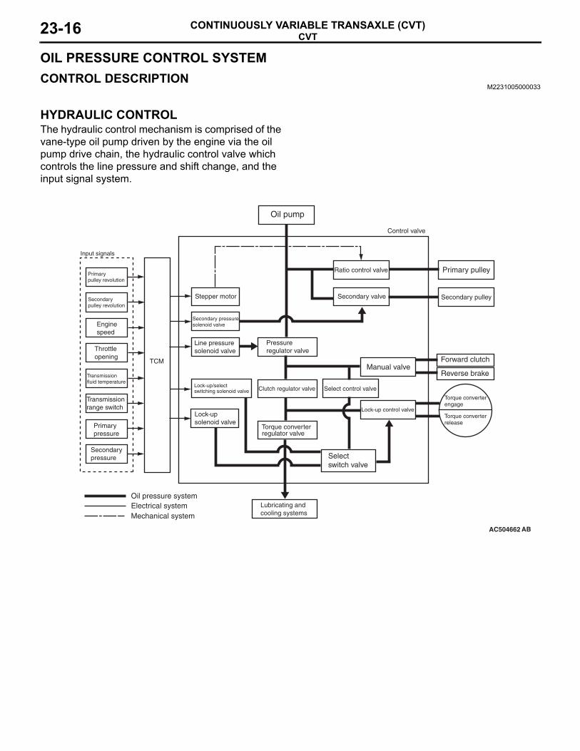
HYDRAULIC CONTROLThe hydraulic control mechanism is comprised of the vane-type oil pump driven by the engine via the oil pump drive chain, the hydraulic control valve which controls the line pressure and shift change, and the input signal system.
.
AC504662 AB
Lock-up/select switching solenoid valve
Ratio control valve
TCM
Primarypulley revolution
Transmission fluid temperature
Lubricating and cooling systems
Torque converterengage
Oil pump
Primary pulley
Secondary pulley
Forward clutch
Reverse brakeManual valve
Secondary valve
Control valve
Mechanical system
Oil pressure systemElectrical system
Selectswitch valve
Select control valve
Pressureregulator valve
Clutch regulator valve
Torque converterregulator valve
Lock-up control valveLock-upsolenoid valve
Transmission range switch
Primarypressure
Enginespeed
Secondarypulley revolution
Throttleopening
Secondary pressuresolenoid valve
Line pressuresolenoid valve
Stepper motor
Input signals
Secondarypressure
Torque converterrelease
CVTCONTINUOUSLY VARIABLE TRANSAXLE (CVT) 23-17
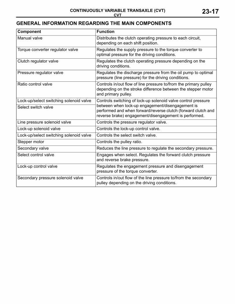
GENERAL INFORMATION REGARDING THE MAIN COMPONENTSComponent FunctionManual valve Distributes the clutch operating pressure to each circuit,
depending on each shift position.Torque converter regulator valve Regulates the supply pressure to the torque converter to
optimal pressure for the driving conditions.Clutch regulator valve Regulates the clutch operating pressure depending on the
driving conditions.Pressure regulator valve Regulates the discharge pressure from the oil pump to optimal
pressure (line pressure) for the driving conditions.Ratio control valve Controls in/out flow of line pressure to/from the primary pulley
depending on the stroke difference between the stepper motor and primary pulley.
Lock-up/select switching solenoid valve Controls switching of lock-up solenoid valve control pressure between when lock-up engagement/disengagement is performed and when forward/reverse clutch (forward clutch and reverse brake) engagement/disengagement is performed.
Select switch valve
Line pressure solenoid valve Controls the pressure regulator valve.Lock-up solenoid valve Controls the lock-up control valve.Lock-up/select switching solenoid valve Controls the select switch valve.Stepper motor Controls the pulley ratio.Secondary valve Reduces the line pressure to regulate the secondary pressure.Select control valve Engages when select. Regulates the forward clutch pressure
and reverse brake pressure.Lock-up control valve Regulates the engagement pressure and disengagement
pressure of the torque converter.Secondary pressure solenoid valve Controls in/out flow of the line pressure to/from the secondary
pulley depending on the driving conditions.

CVTCONTINUOUSLY VARIABLE TRANSAXLE (CVT)23-18
SHIFT MECHANISMM2231001200013
SHIFTING FROM LOW TO HIGH
• No line pressure is applied to the primary pulley because the line pressure circuit is closed by the ratio control valve.
• The line pressure is applied to the secondary pul-ley because the secondary valve has moved downwards.
AC504742 AB
Stepper motor
Ratio control valvePulley ratio linkage
Secondary pulley
Line pressure
Primary pulley
Secondary valve

CVTCONTINUOUSLY VARIABLE TRANSAXLE (CVT) 23-19
• The pulley ratio linkage moves to the left by the stepper motor. This moves the ratio control valve linked to the pulley ratio linkage to open the line pressure circuit, and then the line pressure is applied to the primary pulley.
• The secondary valve moves upwards to drain the fluid in the secondary pulley.
AC504743AB
Stepper motor
Ratio control valvePulley ratio linkage
Secondary pulley
Line pressure
Primary pulley
Secondary valve

CVTCONTINUOUSLY VARIABLE TRANSAXLE (CVT)23-20
• The line pressure applied to the primary pulley moves the movable pulley to the right, pressing the steel belt outwards to expand.
• When the movable pulley of the primary pulley moves to the right, the ratio control valve starts moving to the right via the pulley ratio linkage linked to the movable pulley.
• The steel belt is pulled toward the primary pulley side to move the movable pulley of the secondary pulley to the right.
AC504744AB
Steel belt
Adjustable pulley
Stepper motor
Ratio control valvePulley ratio linkage
Secondary pulley
Line pressure
Primary pulley
Secondary valve
Adjustable pulley

CVTCONTINUOUSLY VARIABLE TRANSAXLE (CVT) 23-21
• When the movable pulley of the secondary pulley moves to the right, the ratio control valve also moves to the right to close the line pressure cir-cuit. This completes the shift change process.
• The secondary valve moves downwards to apply the line pressure to the secondary pulley, clamp-ing the steel belt.
AC504745 AB
Steel belt
Stepper motor
Ratio control valvePulley ratio linkage
Secondary pulley
Line pressure
Primary pulley
Secondary valveAdjustable pulley

CVTCONTINUOUSLY VARIABLE TRANSAXLE (CVT)23-22
SHIFTING FROM HIGH TO LOW
• The pulley ratio linkage moves to the right by the stepper motor. This moves the ratio control valve linked to the pulley ratio linkage to drain the fluid in the primary pulley.
• The line pressure is applied to the secondary pul-ley because the secondary valve has moved downwards.
AC504746 AB
Stepper motor
Ratio control valvePulley ratio linkage
Secondary pulley
Line pressure
Primary pulley
Secondary valve

CVTCONTINUOUSLY VARIABLE TRANSAXLE (CVT) 23-23
• The line pressure applied to the secondary pulley moves the movable pulley to the left, pressing the steel belt outwards to expand.
• The steel belt is pulled toward the secondary pul-ley side to move the movable pulley of the pri-mary pulley to the left.
• When the movable pulley of the primary pulley moves to the left, the ratio control valve starts moving to the left via the pulley ratio linkage linked to the movable pulley.
AC504747AB
Steel belt
Stepper motor
Ratio control valvePulley ratio linkage
Secondary pulley
Line pressure
Primary pulley
Secondary valve
Adjustable pulley
Adjustable pulley

CVTCONTINUOUSLY VARIABLE TRANSAXLE (CVT)23-24
• When the movable pulley of the secondary pulley moves to the left to press the steel belt outwards to expand, the movable pulley of the primary pul-ley moves further to the left accordingly.
• When the movable pulley of the primary pulley moves to the left, the ratio control valve also moves to the left to close the drain circuit. This completes the shift change process.
AC504748AB
Steel belt
Stepper motor
Ratio control valvePulley ratio linkage
Secondary pulley
Line pressure
Primary pulley
Secondary valve
Adjustable pulley
Adjustable pulley

CVTCONTINUOUSLY VARIABLE TRANSAXLE (CVT) 23-25
ELECTRONIC CONTROL SYSTEMCONTROL DESCRIPTION
M2231005000044
The electronic control mechanism is comprised of various sensors, actuators, and TCM which controls them.TCM calculates the vehicle status from various sen-sor information and drives each solenoid valve to perform the following controls:• Shift control (INVECS-III, sport mode <Vehicles
without sport mode>)
• Line pressure control• Control between N (P) and D (R)• Direct control• Engine and CVT integrated control (CAN commu-
nication)• Self-diagnosis function
CONTROL SYSTEM DIAGRAM
.
AC610161AB
ECM
ABS-ECU
TCM
Lock-up/select switching solenoid valve
Transaxle body
Variable link
ETACS-ECU
Accelerator pedalposition sensor
Crankshaftposition sensor
Secondarypulley
Belt
Primarypulley
Stepper motor
Secondary pressure sensor
Line pressure solenoid valve
Secondary pressure solenoid valve
Lock-up solenoid valve
Secondary pulley speed sensor
Transmission fluid temperature sensor
CAN communication
Primary pulley speed sensor
Primary pressure sensor
Shift switch assembly<Vehicles with sport mode>
Transmission rangeswitch
Paddle shift switch<Vehicles with sport mode>

CVTCONTINUOUSLY VARIABLE TRANSAXLE (CVT)23-26
SENSOR LIST
CVT CONTROLM2231001400017
INVECS-IIIINVECS-III has been newly developed based on INVECS-II utilizing continuous variable characteris-tics of CVT.
To select the pulley ratio which can provide the driv-ing force corresponding to the driver's intention and vehicle conditions. TCM selects the optimal pulley ratio and determines the shift strategy to obtain it by detecting the vehicle driving conditions such as the
vehicle speed, accelerator angle. Then, it outputs the command to the stepper motor, controls in/out flow of the line pressure to/from the primary pulley, positions the movable pulley of the primary pulley, and controls the pulley ratio.
. Engine brake feature on the descending slopePulley ratio is controlled to obtain the engine brake suitable for the driver�s feelings.
.
Name FunctionSensor Primary pulley speed sensor Outputs the primary pulley (input shaft) speed as a
pulse signal to TCM.Secondary pulley speed sensor Outputs the secondary pulley (output shaft) speed
as a pulse signal to TCM. The pulse signal is converted to the vehicle speed by TCM.
Transmission fluid temperature sensor Detects the transmission fluid temperature.Primary pressure sensor Detects the pressure applied to the primary pulley.Secondary pressure sensor Detects the pressure applied to the secondary
pulley.Transmission range switch Detects the selector lever position by the
contact-type switch.Shift switch assembly <Vehicles with sport mode>
Detects the request in the sport mode by the contact-type switch at the selector lever.
Paddle shift switch <Vehicles with sport mode>
Detects the operation status of the paddle shift switch.
AC504721
Input signals
Target wave pattern creation section
Gear changing mechanism control section
Selects the pulley ratio and determines the pulley change method.
Determines how the stepper motor works to change pulley according to the target wave pattern.
TCM
AB
Stepper motor Primary pulley

CVTCONTINUOUSLY VARIABLE TRANSAXLE (CVT) 23-27
Engine brake learning feature on the descending slope
Learning compensation is made to meet the tastes of a driver by judging the amount of the engine brake from the application of the accelerator or the brake..
Driving feature on the ascending slope
If the foot leaves the accelerator pedal during driving on the ascending slope (called lift foot), driving capa-bility is secured by preventing excessive upshifting..
AC610382 AB
Throttle opening
Pulley ratio
Acceleration
0%
100%
HIGH
LOW
0
Often use accelerator
Often use brake
Often use accelerator
Often use brake
AC610384
0%
100%
20%
40%
80%
60%
AB
Target primaryrevolution speed
Throttle opening
When driving fast on the ascendingslope
When driving in anormal condition
Increasing the target primaryrevolution speed
Target primaryrevolution speedlower limit value
Vehicle speed

CVTCONTINUOUSLY VARIABLE TRANSAXLE (CVT)23-28
Learning feature corresponding to tastes and habits of drivers
Ratio patterns are continuously switched according to the driving method of the driver.
RATIO PATTERNThe pulley ratio is controlled based on the ratio pat-tern for each predetermined range to achieve the optimal pulley ratio.
<D RANGE>
The shift change is performed in the entire shift range from the lowest to the highest pulley ratio.
AC610398 AB
Target primaryrevolution speed
Cruising onflat road
Target primaryrevolution speedlower limit value
Secondary revolution speed (vehicle speed)
Driving on theascending slopeor driving fast
AC611605AB
OD
Low
Engine speed (r/min)
Vehicle speed km/h (mph)
0 (0) 100 (62) 150 (93)50 (31)
1,000
2,000
4,000
3,000
5,000
7,000
6,000
200 (124)
Throttle opening 0%
Throttle opening100%
Throttle opening 50%

CVTCONTINUOUSLY VARIABLE TRANSAXLE (CVT) 23-29
<L RANGE (VEHICLES WITHOUT SPORT MODE)>
By limiting the shift range to the area around the low-est pulley ratio, the powerful driving force and engine brake is secured.
AC611606AB
OD
Low
Engine speed (r/min)
Vehicle speed km/h (mph)
0 (0) 100 (62) 150 (93)50 (31)
1,000
2,000
4,000
3,000
5,000
7,000
6,000
200 (124)
Throttle opening 0%
Throttle opening100%
Throttle opening 50%
CVTCONTINUOUSLY VARIABLE TRANSAXLE (CVT)23-30
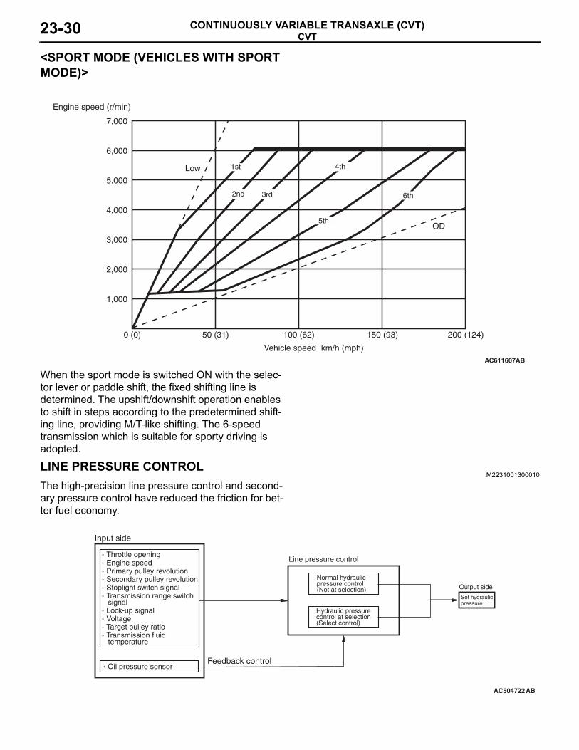
<SPORT MODE (VEHICLES WITH SPORT MODE)>
When the sport mode is switched ON with the selec-tor lever or paddle shift, the fixed shifting line is determined. The upshift/downshift operation enables to shift in steps according to the predetermined shift-ing line, providing M/T-like shifting. The 6-speed transmission which is suitable for sporty driving is adopted.
LINE PRESSURE CONTROLM2231001300010
The high-precision line pressure control and second-ary pressure control have reduced the friction for bet-ter fuel economy.
AC611607AB
OD
Low
Engine speed (r/min)
Vehicle speed km/h (mph)
0 (0) 100 (62) 150 (93)50 (31)
1,000
2,000
4,000
3,000
5,000
7,000
6,000
200 (124)
1st
2nd 3rd
4th
5th
6th
AC504722
· Throttle opening· Engine speed· Primary pulley revolution· Secondary pulley revolution· Stoplight switch signal· Transmission range switch signal· Lock-up signal· Voltage· Target pulley ratio· Transmission fluid temperature
Feedback control
Line pressure control
Normal hydraulic pressure control (Not at selection)
Hydraulic pressure control at selection (Select control)
Set hydraulic pressure
AB
· Oil pressure sensor
Input side
Output side

CVTCONTINUOUSLY VARIABLE TRANSAXLE (CVT) 23-31
NORMAL HYDRAULIC CONTROLThe optimal line pressure and secondary pressure are determined by the accelerator angle, engine speed, primary pulley (input) speed, secondary pul-ley (output) speed, stoplight switch signal, transmis-sion range switch signal, lock-up signal, voltage, target pulley ratio, fluid temperature, and oil pres-sure, depending on driving conditions.
SECONDARY PRESSURE FEEDBACK CONTROLIn the normal hydraulic control or select hydraulic control, the more precise secondary pressure has been set by detecting the secondary pressure with an oil pressure sensor, and by performing the feed-back control.
DIRECT CONTROL (TORQUE CONVERTER CLUTCH CONTROL)M2231007000039
.
By carefully controlling the direct operating pressure depending on the driving conditions, the shock-free direct operation from low speed has been achieved.
CONTROL BETWEEN N (P) AND D (R)M2231001500014
When operation between N (P) and D (R) ranges is performed, the optimal operating pressure is deter-mined by the accelerator angle, engine speed, and secondary pulley (output) speed to reduce the shock caused by selecting.
AC611608AB
OD
Low
Engine speed (r/min)
Vehicle speed km/h (mph)
0 (0) 100 (62) 150 (93)50 (31)
1,000
2,000
4,000
3,000
5,000
7,000
6,000
200 (124)
Disengaged
Partial lock-up zone
Lock-up

CVTCONTINUOUSLY VARIABLE TRANSAXLE (CVT)23-32
CONTROLLER AREA NETWORK (CAN) COMMUNICATIONM2231017000030
The information transaxle between each control unit has been ensured via the CAN communication. For further details on CAN, refer to GROUP 54C, CAN P.54C-2.
ENGINE AND CVT INTEGRATED CONTROL (CAN COMMUNICATION CONTROL)• To control better shift feeling and preventing the
engine speed from dropping, the ECM and TCM communicate each other to exchange the engine output control signal to provide the real-time link-age control depending on the vehicle driving con-ditions.
• TCM transmits information such as the rapid deceleration signal, lock-up in progress signal, torque down request signal to the ECM. It also receives information such as the torque down permission/prohibition signal, lock-up permis-sion/prohibition signal, accelerator angle.
SELF-DIAGNOSIS FUNCTIONM2231001600011
DIAGNOSTIC FUNCTIONTCM is equipped with the diagnostic function to mon-itor the input signals from each sensor and output signals from the actuators. If abnormality occurs in the signal system, the diagnostic function memorises the abnormal symptoms and outputs a diagnosis code via M.U.T.-III.
FAIL-SAFE FUNCTIONIf abnormality occurs in signals from various sensors, switches, or solenoids, this function allows control-ling them with the minimum adverse effect to the driving performance. The following shows the fail-safe controls when an abnormal signal is input to TCM from each sensor.Item Control contentSecondary pulley speed sensor Performs the shift control depending on the accelerator angle. Also,
prohibits the sport mode and controls as the D range <Vehicles with sport mode>.
Primary pulley speed sensor Performs the shift control depending on the accelerator angle and secondary pulley rotation (vehicle speed). Also, prohibits the sport mode and controls as the D range <Vehicles with sport mode>.
Transmission range switch Controls as the D range.Transmission fluid temperature sensor
Controls using the fixed value for the fail-safe function.
Secondary pressure sensor Stops the secondary pressure feedback control and controls the line pressure using the fixed value for the fail-safe function. Also, suppresses the engine torque.
Primary pressure sensor Stops the primary pressure feedback control and controls the line pressure using the fixed value for the fail-safe function. Also, suppresses the engine torque.
Line pressure solenoid valve Switches the line pressure solenoid valve OFF to achieve the maximum line pressure.

CVTCONTINUOUSLY VARIABLE TRANSAXLE (CVT) 23-33
Secondary pressure solenoid valve Switches the secondary pressure solenoid valve OFF to achieve the maximum secondary pressure.
Lock-up solenoid valve Switches the lock-up solenoid valve OFF to release lock-up.Stepper motor Switches all the coils A to D of the stepper motor OFF to retain the
pulley ratio just before the abnormality occurs.Lock-up/select switching solenoid valve
Switches the lock-up/select switching solenoid valve OFF to release lock-up.
Back-up power supply If the control memory back-up power supply from the battery is not supplied to TCM, limits the engine torque to protect the transmission main body. After the normal power is supplied, turning the key switch from OFF to ON once resumes the normal status.
Paddle shift switch <Vehicles with sport mode>
Prohibits the paddle shift operation.
Shift switch assembly <Vehicles with sport mode>
Prohibits the sport mode operation.
Item Control content

TRANSAXLE CONTROLCONTINUOUSLY VARIABLE TRANSAXLE (CVT)23-34
TRANSAXLE CONTROLGENERAL INFORMATION
M2232000600011The selector lever with the gate-type has been adopted. For vehicles with sport mode, in addition to the manual gate of selector lever, the paddle shift has been equipped around the steering wheel to achieve "Fun to Drive." The selector lever has the following features:• The shift gate configuration and the operating
power at each shift position have been properly tuned, ensuring the firm and smooth operation feel.
• The sport mode (6-speed) has been installed to allow the driver to shift manually according to his/her intention. <Vehicles with sport mode>
• The shift knob painted in metallic silver with a high-grade appearance has been adopted, and for higher level specifications, the genu-ine-leather shift knob has been provided.
• The main components have been made of resin to reduce weight and number of components.
• The electrical control-type shift lock mechanism with the solenoid to facilitate the tuning work in assembly.
• The cable control-type key interlock mechanism which is field proven has been adopted.
AC611629
L+
-E
+
-
AB
Transaxle control cable
Key interlock cable
Selector leverassembly
<Vehicles without sport mode> <Vehicles with sport mode>

TRANSAXLE CONTROLCONTINUOUSLY VARIABLE TRANSAXLE (CVT) 23-35
SELECTOR LEVER ASSEMBLYM2232002000189
The electrical control-type shift lock (the shift lever is locked in the "P" position if the brake pedal is not depressed) mechanism has been adopted for the selector lever assembly. The functions of each switch are as follows:
AC610078AB
Shift lock release button
Shift indicator valve
Shift switch assembly
P positiondetect switch
Shift lock control relay
Shift lock solenoid
Name FunctionShift lock release button If the shift lock system has failed, remove the cover
and press the shift lock release button to release the shift lock forcibly (mechanically).
Shift indicator bulb Illuminates the present selector lever position in the shift indicator.
Shift switch assembly <Vehicles with sport mode> Detects the selector lever activation in sport mode.Shift lock solenoid Switches the shift lock mechanism ON/OFF.Shift lock control relay Switches the shift lock solenoid power supply circuit
ON/OFF.P position detection switch Detects the "P" position.

TRANSAXLE CONTROLCONTINUOUSLY VARIABLE TRANSAXLE (CVT)23-36
CVT ERRONEOUS OPERATION PREVENTION MECHANISMSSHIFT LOCK MECHANISM
M2232000400017
STRUCTURE OF SHIFT LOCK SYSTEM This system is comprised of the following compo-nents.• Lock lever
• Shift lock solenoid• Shift lock control relay• P position detection switch
SHIFT LOCK CIRCUITWhen all of the following conditions are true, the shift lock sole-noid is energised, allowing the selector lever to move from the P position to another position.• Ignition switch: ON• P position detection switch: ON (the selector lever is in the
P position)• Stoplight switch: ON (brake pedal is depressed)
OPERATIONAL DESCRIPTION.
SHIFT LOCK STATUSWith the shift lock status, the shift lock solenoid is not ener-gized, so when the select operation of the selector lever is attempted, no select operation is possible because the lock lever blocks the lever assembly path.
.
AC507425AB
P positiondetect switch
Shift locksolenoid
Shift lockcontrol relay
To stoplightswitch
To ignitionswitch
AC610121AB
Lock lever inhibits selecting operation of the lever sub-assembly.
Lever sub assembly
Shift locksolenoid
Lock lever

TRANSAXLE CONTROLCONTINUOUSLY VARIABLE TRANSAXLE (CVT) 23-37
SHIFT LOCK RELEASE STATUSWhen the ignition switch is ON, the selector lever is in the P position, and the brake pedal is depressed, the shift lock sole-noid is energized to move the shift lock solenoid toward the direction A shown in the figure. Then the lock lever linked to the shift lock solenoid moves as shown in the figure, and no longer blocks the lever sub assembly path when the select operation is performed, enabling the operation.
.
RELEASE USING THE SHIFT LOCK RELEASE BUTTONIf the shift lock no longer operates properly due to a dead bat-tery or the like, remove the cover and press the shift lock release button to enable shift operation from the P position. Pressing the shift lock release button moves the lock lever to the position shown in the figure, enabling shift operation.
AC610122 AB
A
Lock lever moves to allow selecting operation of the lever sub assembly.
Lever sub assembly
Shift locksolenoid
Lock lever
AC610123AB
Lock lever
Shift lock release button operation direction
Cover

TRANSAXLE CONTROLCONTINUOUSLY VARIABLE TRANSAXLE (CVT)23-38
KEY LOCK MECHANISMM2232000500014
This mechanism is basically same as that used for OUTLANDER.
PADDLE SHIFT <VEHICLES WITH SPORT MODE>M2232000300021
The paddle-shaped upshift/downshift lever has been fitted near the steering wheel to allow the driver to operate upshift or downshift with his/her hands kept on the steering wheel. The paddle shift has the fol-lowing features:• The lever on the right of the vehicle is for upshift
and that on the left is for downshift.• As the paddle shift is fixed on the steering column
to maintain the certain position regardless of the steering wheel angle, the proper operation can be performed without possibility of improper up/down position even when the steering wheel is fully turned.
• The paddle shift can perform the upshift/down-shift operation whether the selector lever is in the sport mode or automatic shifting to provide a rapid shift operation.
NOTE: When the mode is changed to the sport mode using the paddle shift during automatic gear shifting, the sport mode is cancelled under the following conditions..• The upshift lever is pulled for 2 seconds or
more.• The vehicle is stopped.• No operation is carried out for 4 minutes and
25 seconds.• The main components have been made of mag-
nesium alloy to achieve the considerable weight reduction and pursue a sporty impression.
AC611129
AC609992
AB
Up shift lever
Up shift (operate it for 2 seconds or more to return to D range.)
Down shift lever
Down shift