CONTINUOUSLY VARIABLE TRANSAXLE SYSTEM > PRECAUTIONwebpages.charter.net/scott.mcclure/Yaris/K41A...
278
CONTINUOUSLY VARIABLE TRANSAXLE SYSTEM > PRECAUTION 1.IGNITION SWITCH EXPRESSIONS 1. The type of ignition switch used on this model differs according to the specifications of the vehicle. The expressions listed in the table below are used in this section. Expression Ignition Switch (Position) Engine Switch (Condition) Ignition switch off LOCK Off Ignition switch ACC ACC On (ACC) Ignition switch ON ON On (IG) Engine start START Start NOTICE: • Perform Reset Memory (AT initialization) when replacing the continuously variable transaxle (CVT) assembly or ECM (). • Performing reset memory/initialization will clear the learned values of both the yaw rate and acceleration sensor (deceleration sensor 0 point calibration) and the CVT oil pressure (CVT oil pressure calibration). Make sure to perform reset memory, yaw rate and acceleration sensor 0 point calibration, and CVT oil pressure calibration when replacing any of the parts shown in the following table: Replaced Part • Continuously variable transaxle assembly • ECM • Oil pressure sensor • Yaw rate and acceleration sensor
Transcript of CONTINUOUSLY VARIABLE TRANSAXLE SYSTEM > PRECAUTIONwebpages.charter.net/scott.mcclure/Yaris/K41A...

CONTINUOUSLY VARIABLE TRANSAXLE SYSTEM > PRECAUTION 1.IGNITION SWITCH EXPRESSIONS
1. The type of ignition switch used on this model differs according to the specifications of the vehicle. The expressions listed in the table below are used in this section.
Expression Ignition Switch (Position) Engine Switch (Condition) Ignition switch off LOCK Off
Ignition switch ACC ACC On (ACC) Ignition switch ON ON On (IG)
Engine start START Start NOTICE:
• Perform Reset Memory (AT initialization) when replacing the continuously variable transaxle (CVT) assembly or ECM ().
• Performing reset memory/initialization will clear the learned values of both the yaw rate and acceleration sensor (deceleration sensor 0 point calibration) and the CVT oil pressure (CVT oil pressure calibration). Make sure to perform reset memory, yaw rate and acceleration sensor 0 point calibration, and CVT oil pressure calibration when replacing any of the parts shown in the following table:
Replaced Part • Continuously variable
transaxle assembly • ECM • Oil pressure sensor • Yaw rate and
acceleration sensor

• If the ECM is replaced, register the ECM communication ID for Immobiliser System (Refer to the Service Bulletin for Registration).
CAUTION: When using compressed air, always aim away from yourself to prevent CVT fluid or kerosene from spraying on your face.
NOTICE:
• Clean any sand, dirt, or other matter off of the transaxle before removal and disassembly, in order to prevent contamination of the inside components.
• Do not tilt the oil-pan side of the transaxle up until the oil pan is removed, to prevent foreign matter from contaminating the inside of the valve body.
• When disassembling light alloy parts such as the case, do not pry them with a screwdriver or similar tool. Instead, tap the parts with a plastic hammer to separate them.
• Do not wear cloth gloves or use cloth to handle parts during removal, disassembly, or installation of the transaxle. Instead, work with bare hands or wear synthetic gloves, to prevent cloth fiber from entering the transaxle.
• Disassembled parts should be arranged in order and covered with a piece of cloth to prevent dust contamination.
• Before reassembly, all parts should be cleaned, dried, and coated with Toyota Genuine CVT Fluid TC. However, do not use alkaline cleaners to clean aluminum and rubber components. Also, rubber components such as O-rings, gaskets, and oil seals should never be cleaned with solvents or gasoline under any circumstances.
• Apply Toyota Genuine CVT Fluid TC to all sliding surfaces and rotating parts. • Before installing O-rings and oil seal rings, coat them with Toyota Genuine CVT
Fluid TC and be sure to not damage them. • Do not clamp components in a vice without the use of protective aluminum plates. • Be careful to not damage the matching surfaces of components, because damage
to these surfaces can cause oil leaks. • Before applying sealant, remove all of the old sealant and thoroughly clean the
surfaces with non-residue solvent. • Use of Toyota Genuine CVT fluid TC is recommended.

CONTINUOUSLY VARIABLE TRANSAXLE SYSTEM > PARTS LOCATION


1 / 3


2 / 3


3 / 3
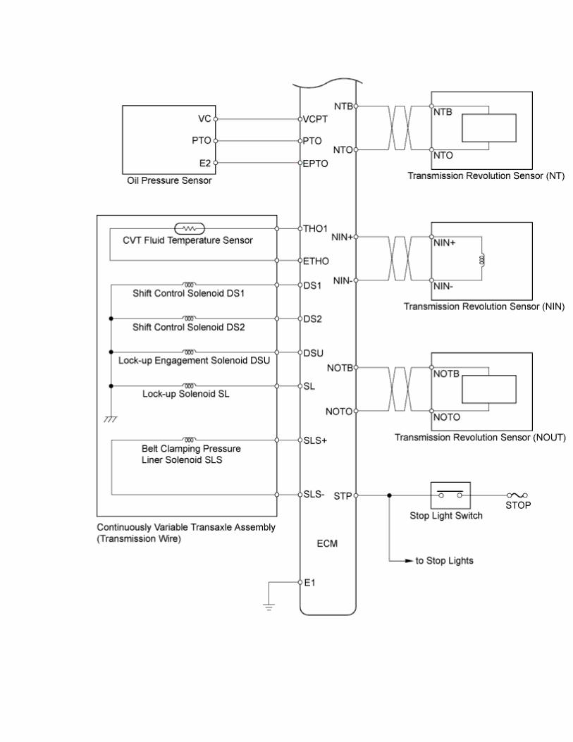
CONTINUOUSLY VARIABLE TRANSAXLE SYSTEM > SYSTEM DIAGRAM

The configuration of the electronic control system in K41A continuously variable transaxle is as shown in the following chart.


CONTINUOUSLY VARIABLE TRANSAXLE SYSTEM > SYSTEM DESCRIPTION SYSTEM DESCRIPTION

1. The Continuously Variable Transaxle (CVT) is an automatic transmission that electronically controls shift timing using the Transmission Control Module (ECM). The ECM detects electrical signals that indicate engine and driving conditions, and controls shift points based on driver habits and road conditions. In addition, the CVT has the following features:
• Diagnostic function • Fail-safe function when a malfunction occurs
FUNCTION OF MAIN COMPONENTS
Component Outline Shift control solenoid DS1
The oil flow to primary pulley is controlled according to vehicle speed and accelerator opening.
Shift control solenoid DS2
The oil flow from primary pulley is controlled according to vehicle speed and accelerator opening.
Lock-up solenoid SL The usage of belt clamping pressure liner solenoid SLS is switched.
Lock-up engagement solenoid DSU The oil pressure for lock-up clutch engagement is controlled.
Belt clamping pressure liner solenoid SLS
Belt clamping pressure is controlled according to the input torque. Moreover, while forward and reverse clutch is engaged, or during neutral control, forward and reverse clutch oil pressure is controlled.
Transmission revolution sensor
(NIN) Primary pulley revolution speed is detected.
Transmission revolution sensor
(NOUT) Secondary pulley revolution speed is detected.
Transmission revolution sensor
(NT) Input turbine revolution speed is detected.
CVT oil temperature sensor CVT fluid temperature is detected.
CVT oil pressure sensor CVT oil pressure for belt clamping force is detected.
Engine coolant temperature sensor Engine coolant temperature is detected.
Throttle position Opening of the throttle valve is detected.

sensor Stop light switch ON or OFF of the brake pedal is detected.
Park/neutral position switch The position of the shift lever is detected.
ECM The transmission is controlled based on the signal from each sensor. It has the diagnosis mode and the fail-safe function.
DLC3 DTCs and ECM data can be read by connecting the diagnosis tool.
CONTINUOUSLY VARIABLE TRANSAXLE SYSTEM > HOW TO PROCEED WITH

TROUBLESHOOTING HINT:
• The ECM of this system is connected to the CAN communication system. Therefore, before starting troubleshooting, be sure to check that there is no trouble in the CAN communication system.
• *: Use the intelligent tester.
1.VEHICLE BROUGHT TO WORKSHOP NEXT 2.CUSTOMER PROBLEM ANALYSIS NEXT 3.INSPECT BATTERY VOLTAGE
Standard Voltage: 11 to 14 V If the voltage is below 11 V, recharge or replace the battery before proceeding.
NEXT 4.CONNECT INTELLIGENT TESTER TO DLC3*

NEXT 5.CHECK AND CLEAR DTCS AND FREEZE FRAME DATA*
1. Refer to the DTC Check/Clear ().
NEXT 6.VISUAL INSPECTION NEXT 7.SETTING CHECK MODE DIAGNOSIS*
1. Refer to the Check Mode Procedure ().
NEXT 8.DTC CHECK*
1. Refer to DTC Check/Clear ().
Result Proceed to DTC not output A
DTC output B

B. GO TO STEP 13 A 9.BASIC INSPECTION
1. Refer to CVT Fluid ().
2. Refer to Park/Neutral Position Switch ().
3. Refer to Shift Lever Assembly ().
NG. GO TO STEP 12 OK 10.MECHANICAL SYSTEM TEST*
1. Refer to the Mechanical System Test ().
NG. GO TO STEP 12 OK 11.HYDRAULIC TEST*
1. Refer to the Hydraulic Test ().
NG. GO TO STEP 12 OK

GO TO STEP 14 12.COMPONENT INSPECTION NEXT
GO TO STEP 16 13.DTC CHART
1. Refer to the Diagnostic Trouble Code Chart ().
NEXT 14.CIRCUIT INSPECTION NEXT 15.IDENTIFICATION OF PROBLEM NEXT 16.REPAIR OR REPLACE NEXT

17.CONFIRMATION TEST NEXT
END
CONTINUOUSLY VARIABLE TRANSAXLE SYSTEM > ROAD TEST

PROBLEM SYMPTOM CONFIRMATION
1. Try to reproduce symptoms based on the result of the customer problem analysis. If the problem is that the transaxle does not change gear ratios or changes ratios at the wrong engine speed, conduct the following road test referring to the speed variation chart and attempt to duplicate the problem symptoms.
ROAD TEST CAUTION:
Strictly observe posted speed limits, traffic laws, and road conditions when performing the road test.
NOTICE:
• This test must be conducted after checking and confirming that the engine is operating normally.
• Perform this test while the CVT fluid temperature is between 50 to 100°C (122 to 212°F).
• Perform the test with the A/C off.
HINT:
• Lock-up control will not operate when the CVT fluid temperature is 40°C (104°F) or less and the vehicle speed is 60 km/h (37 mph) or less or when the CVT fluid temperature is 5°C (41°F) or less.
• Lock-up control will not operate when the engine coolant temperature is 30°C (86°F) or less.
• The lock-up OFF vehicle speed may vary depending on the electrical load and air conditioning and brake operations.
• Keep a constant accelerator pedal angle to maintain the specified vehicle speed. • When kicking down with the accelerator pedal, read the engine speed
immediately after the pedal is pushed down.
Speed Variation Chart
Accelerator Pedal Position ( Vehicle speed)

Shift Lever
Position (Engine Speed)
Kick-down (40
km/h) (25 mph)
Kick-down (70
km/h) (43 mph)
Kick-down (100
km/h) (62 mph)
Constant Angle
(40 km/h)(25 mph)
Constant Angle
(70 km/h)(43 mph)
Constant Angle (100
km/h) (62 mph)
Kick-down (70
km/h) (43 mph)
D (rpm)
4300 to 4900
4800 to 5500
5200 to 5900
1000 to 1400
1300 to 1700
1900 to 2400
3000 or more
S (rpm)
4300 to 4900
4800 to 5500
5200 to 5900
1900 to 2400
2800 to 3400
3600 to 4200
3000 or more
B (rpm)
4300 to 4900
4800 to 5500
5200 to 5900
3250 to 3750
4700 to 5200
5300 to 5900
3000 or more
Lock-up Chart
Lock-up Condition (Accelerator Pedal Position)
Shift Lever Position (Vehicle Speed)
Lock-up ON (5%)
Lock-up OFF (0%)
D km/h (mph)
8 to 28 (5 to 17)
8 to 18 (5 to 11)
S km/h (mph)
30 to 44 (19 to 27)
22 to 28 (14 to 17)
B km/h (mph)
30 to 44 (19 to 27)
22 to 28 (14 to 17)
1. D position test Move the shift lever to D and fully depress the accelerator pedal. Check the following:
1. Check up-shift operation. Check if the gear ratio changes during normal driving (average urban driving).
2. Check for abnormal noises and vibration.
HINT: The check for the cause of abnormal noise and vibration must be done thoroughly as it could also be due to loss of balance in the differential, torque converter clutch, etc.

3. Check kick-down operation. Check if the kick-down engine speeds are as specified in the speed variation chart.
4. Check for abnormal shock and slippage at kick-down. 5. Check the lock-up mechanism.
2. S position test Move the shift lever to S and check the following:
1. Check shift operation • Check if the shift pattern changes in accordance with the S position
pattern as specified in the speed variation chart. • Check for appropriate engine braking force while driving at
approx. 40 km/h (24 mph) with the shift lever in S. 3. B position test
Move the shift lever to B and check the following: • Check if the shift pattern changes in accordance with the B position
pattern as specified in the speed variation chart. • Check for appropriate engine braking force while driving at approx. 40
km/h (24 mph) with the shift lever in B. 4. R position test
Move the shift lever to R and lightly depress the accelerator pedal. Check that the vehicle moves backward without any abnormal noise or vibration.
CAUTION: Before conducting this test ensure that the test area is free from people and obstructions.
5. P position test Stop the vehicle on an incline (more than 5°). Then move the shift lever to P and release the parking brake. Check that the parking lock pawl holds the vehicle in place.

CONTINUOUSLY VARIABLE TRANSAXLE SYSTEM > MECHANICAL SYSTEM TESTS SHIFT TIME LAG TEST NOTICE:
• This test must be conducted after checking and confirming that the engine is operating normally.
• Perform this test while the CVT fluid temperature is between 50 to 100°C (122 to 212°F).
• Perform this test with the A/C off.
HINT: When the shift lever is moved while the engine is idling, there will be a certain time lapse or lag before the shock can be felt. This is used for checking the condition of the clutch and brake.
1. Connect the intelligent tester to the DLC3. 2. Start the engine. 3. Turn the tester on.

4. Enter the following menus: Powertrain / Engine and ECT / Data List. 5. Run the vehicle until the CVT fluid temperature has reached 50 to 100°C (122 to
212°F). 6. Allow the engine to idle with the air conditioning off. 7. Set the parking brake and keep the brake pedal depressed firmly. 8. Check the D position time lag.
1. Move the shift lever to N and wait for 1 minute. 2. Move the shift lever to D and measure the time until the shock is felt. 3. Repeat the 2 steps above 3 times, and calculate the average time of the 3
tests.
Standard value: D position time lag is less than 1.2 seconds
9. Check the R position time lag.
1. Move the shift lever to N and wait for 1 minute. 2. Move the shift lever to R and measure the time until the shock is felt. 3. Repeat the 2 steps above 3 times, and calculate the average time of the 3
tests.
Standard value: R position time lag is less than 1.5 seconds
STALL SPEED TEST CAUTION:
The stall speed test should always be performed with at least 2 people. One person should observe the condition of the wheels and wheel chocks while the other is performing the test.
NOTICE:
• Driving test should be done on a paved surface (a surface that is not slippery). • To ensure safety, perform this test in an open and level area that provides good
traction. • Do not perform the stall speed test for longer than 5 seconds.
HINT: This test is to check the overall performance of the engine.
1. Connect the intelligent tester to the DLC3. 2. Start the engine. 3. Turn the tester on. 4. Enter the following menus: Powertrain / Engine and ECT / Data List.

5. Run the vehicle until the CVT fluid temperature has reached 50 to 100°C (122 to 212°F).
6. Allow the engine to idle with the air conditioning off. 7. Chock all 4 wheels. 8. Set the parking brake and keep the brake pedal firmly depressed with your left
foot. 9. Move the shift lever to D. 10. Depress the accelerator pedal all the way down with your right foot. 11. Read the engine rpm (stall speed) and release the accelerator pedal immediately.
Standard value: 1700 to 2400 rpm
CONTINUOUSLY VARIABLE

TRANSAXLE SYSTEM > HYDRAULIC TEST PERFORM HYDRAULIC TEST
1. Measure the secondary oil pressure.
CAUTION: The secondary oil pressure test should always be carried out with at least 2 people. One person should observe the condition of wheels and wheel chocks while the other is performing the test. NOTICE:
• This test must be conducted after checking and confirming that the engine is operating normally.
• Perform this test while the CVT transaxle fluid temperature is between 50 to 100°C (122 to 212°F).
• Perform the test with the air conditioning off. • Do not perform the stall test for longer than 5 seconds.
5. Fully apply the parking brake and chock the 4 wheels. 6. Connect the intelligent tester to the DLC3. 7. Start the engine. 8. Turn the tester on. 9. Enter the following menus: Power train / Engine and ECT / Active Test / Connect the TC and TE1. 10. Select the Data List menu: A/T Oil Pressure from Engine and ECT. 11. Keep your left foot firmly on the brake pedal and move the shift lever to D. 12. Depress the accelerator pedal as much as possible with your right foot. Quickly read the highest secondary oil pressure reading when the engine speed reaches stall speed.
Specified Secondary Oil Pressure:

Condition kPa (kgf/cm2, psi) Engine Speed
D position stall test 3810 to 4580 kPa (38.9 to 46.7 kgf/cm2, 553 to 664 psi) 1700 to 2400 rpm
13. Keep your left foot firmly on the brake pedal and move the shift lever to R. 14. Depress the accelerator pedal as much as possible with your right foot. Quickly read the highest secondary oil pressure reading when the engine speed reaches stall speed.
Specified Secondary Oil Pressure:
Condition kPa (kgf/cm2, psi) Engine Speed
R position stall test 3810 to 4820 kPa (38.9 to 49.2 kgf/cm2, 553 to 699 psi) 1700 to 2400 rpm
HINT: If the oil pressure exceeds the maximum value or drops below the minimum value, a solenoid valve, regulator valve or modulator valve may be malfunctioning.

CONTINUOUSLY VARIABLE TRANSAXLE SYSTEM > INITIALIZATION NOTICE:
• Performing reset memory/initialization will clear the learned values of both the yaw rate and acceleration sensor (deceleration sensor 0 point calibration) and the CVT oil pressure (CVT oil pressure calibration). Make sure to perform reset memory, yaw rate and acceleration sensor 0 point calibration, and CVT oil pressure calibration when replacing any of the parts shown in the following table:
Replaced Part • Continuously variable
transaxle assembly • ECM • Oil pressure sensor • Yaw rate and
acceleration sensor
• After reset memory, always perform yaw rate and acceleration sensor (deceleration sensor 0 point) calibration first, and then the CVT oil pressure calibration.
RESET MEMORY
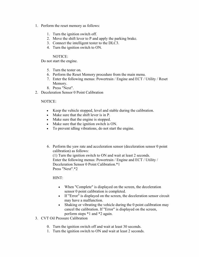
1. Perform the reset memory as follows:
1. Turn the ignition switch off. 2. Move the shift lever to P and apply the parking brake. 3. Connect the intelligent tester to the DLC3. 4. Turn the ignition switch to ON.
NOTICE: Do not start the engine.
5. Turn the tester on. 6. Perform the Reset Memory procedure from the main menu. 7. Enter the following menus: Powertrain / Engine and ECT / Utility / Reset
Memory. 8. Press "Next".
2. Deceleration Sensor 0 Point Calibration
NOTICE:
• Keep the vehicle stopped, level and stable during the calibration. • Make sure that the shift lever is in P. • Make sure that the engine is stopped. • Make sure that the ignition switch is ON. • To prevent idling vibrations, do not start the engine.
6. Perform the yaw rate and acceleration sensor (deceleration sensor 0 point calibration) as follows: (1) Turn the ignition switch to ON and wait at least 2 seconds. Enter the following menus: Powertrain / Engine and ECT / Utility / Deceleration Sensor 0 Point Calibration.*1 Press "Next".*2
HINT:
• When "Complete" is displayed on the screen, the deceleration sensor 0 point calibration is completed.
• If "Error" is displayed on the screen, the deceleration sensor circuit may have a malfunction.
• Shaking or vibrating the vehicle during the 0 point calibration may cancel the calibration. If "Error" is displayed on the screen, perform steps *1 and *2 again.
3. CVT Oil Pressure Calibration
0. Turn the ignition switch off and wait at least 30 seconds. 1. Turn the ignition switch to ON and wait at least 2 seconds.

NOTICE: Do not start the engine.
2. Start the engine and wait at least 5 seconds. 3. Enter the following menus: Powertrain / Engine and ECT / Utility / CVT
Oil Pressure Calibration. 4. Press "Next".
HINT:
• During the CVT oil pressure calibration, the engine idle speed will increase.
• When "Complete" is displayed on the screen, the CVT oil pressure calibration is completed.
• The learned values cannot be cleared by only disconnecting and reconnecting the cable to the negative (-) battery terminal.

CONTINUOUSLY VARIABLE TRANSAXLE SYSTEM > TERMINALS OF ECM ECM
HINT:
Each ECM terminal's standard voltage and resistance is shown in the table below. In the table, first follow the information under "Condition". Look under "Terminal No. (Symbol) " for the terminals to be inspected. The standard voltage and resistance between the terminals is shown under "Specific Condition". Use the illustration above as a reference for the ECM terminals.
Terminals No. (Symbol)
Wiring Color Terminal Description Condition Specified
Condition A18-1 (+B2)
- B8-105 L - BR Power supply for IG Ignition switch ON 11 to 14 V

(E1) A18-2 (+B) - B8-105 (E1) W - BR Power supply for IG Ignition switch ON 11 to 14 V
A18-3 (+BM) - B8-
105 (E1)
R-W - BR
Power supply for back-up memory Always 11 to 14 V
A18-8 (CANH) -
B8-105 (E1) L - BR CAN communication
signal Ignition switch ON
Pulse generation
(See waveform
1)
A18-9 (CANL) -
B8-105 (E1) W - BR CAN communication
signal Ignition switch ON
Pulse generation
(See waveform
2) A18-20
(BATT) - B8-105 (E1)
B - BR Battery Always 11 to 14 V
Ignition switch ON and shift lever P or N position Below 1 V
A18-25 (NSW) - B8-
105 (E1)
GR - BR
Park/Neutral position switch signal Ignition switch ON and
shift lever other than P and N position
11 to 14 V
Ignition switch ON and shift lever S or B position 11 to 14 V
A18-26 (SDSW) -
B8-105 (E1)
L-B - BR
Shift lever position switch signal Ignition switch ON and
shift lever other than S and B position
Below 1 V
Brake pedal depressed 7.5 to 14 VA18-36 (STP) - B8-
105 (E1) Y - BR Stop light switch
signal Brake pedal released Below 1.5 V
A18-44 (MREL) -
B8-105 (E1)
L-Y - BR
Main relay (EFI/ECO) drive signal
Ignition switch ON 11 to 14 V
A18-48 (STA) - B8-
105 (E1)
W-R - BR
Starter relay drive signal input Cranking 6 V or more
Ignition switch ON and shift lever B position 11 to 14 V B8-39 (B) -
B8-105 (E1) LG-B -
BR B shift position switch signal
Ignition switch ON and Below 1 V

shift lever other than B position
B8-54 (SLS+) - B8-
53 (SLS-) V - W-L
Belt clamping pressure liner solenoid (SLS) signal
Engine idling speed
Pulse generation
(See waveform
3)
B8-55 (DS2) - B8-105
(E1)
P-G - BR
Shift control solenoid valve (DS2) signal
Accelerator pedal further depressed after driving at a constant vehicle speed with shift lever in D
Pulse generation
(See waveform
4)
B8-56 (DS1) - B8-105
(E1)
R-L - BR
Shift control solenoid valve (DS1) signal
Accelerator pedal released while driving with shift lever in D
Pulse generation
(See waveform
5) B8-58 (SL) - B8-105 (E1)
P-B - BR
Lock-up solenoid (SL) signal
Shift lever in N → except D
11 to 14 V → 0 to 1.5V
B8-59 (DSU) - B8-105
(E1)
GR-R - BR
Lock-up engagement solenoid (DSU) signal
Lock-up turned from OFF to ON
Pulse generation
(See waveform
6) Ignition switch ON and shift lever D position 11 to 14 V
B8-64 (D) - B8-105 (E1)
G-W - BR
D shift position switch signal Ignition switch ON and
shift lever other than D position
Below 1 V
B8-70 (THO1) -
B8-71 (ETHO)
G-Y - B-W
CVT fluid temperature sensor signal
CVT fluid temperature: 60 to 120°C (140 to 320°F)
0.2 to 1.0 V
B8-73 (PTO) - B8-72 (EPTO)
L-B - W-R
Secondary pulley pressure sensor signal
Engine idling speed and shift lever P position 0.8 to 1.2
B8-74 (VCPT) -
B8-72 (EPTO)
V-W - W-R
Power supply for secondary pulley pressure sensor signal
Ignition switch ON and engine stopped 4.5 to 5.5 V
B8-75 (N) - B8-105 (E1)
L - BR N shift position switch signal
Ignition switch ON and shift lever N position 11 to 14 V

Ignition switch ON and shift lever other than N position
Below 1 V
Ignition switch ON and shift lever R position 11 to 14 V
B8-76 (R) - B8-105 (E1) R - BR R shift position
switch signal Ignition switch ON and shift lever other than R position
Below 1 V
Ignition switch ON and shift lever P position 11 to 14 V
B8-77 (P) - B8-105 (E1)
L-R - BR
P shift position switch signal Ignition switch ON and
shift lever other than P position
Below 1 V
B8-99 (NIN+) - B8-100 (NIN-)
L - LG Transmission revolution sensor (NIN) signal
When driving with shift lever in D, vehicle speed approx. 6 km/h (3.7 mph) and engine speed approx. 700 rpm
Pulse generation
(See waveform
7)
B8-102 (NOTO) -
B8-101 (NOTB)
L - W Transmission revolution sensor (NOUT) signal
When driving with shift lever in D, vehicle speed approx. 12 km/h (7.5 mph) and engine speed approx. 1150 rpm
Pulse generation
(See waveform
8) B8-105 (E1)
- Body ground
BR - Body
ground Ground Always Below 1 Ω
B8-124 (NTO) - B8-123 (NTB)
V - P Transmission revolution sensor (NT) signal
When driving with shift lever in D, vehicle speed approx. 12 km/h (7.5 mph) and engine speed approx. 1150 rpm
Pulse generation
(See waveform
9)

1. Waveform 1 (Reference)
Terminal CANH - E1
Tool setting 1 V/DIV, 10 μs/DIV
Vehicle conditions Ignition switch ON
2.
3. Waveform 2 (Reference)
Terminal CANL - E1
Tool setting 1 V/DIV, 10 μs/DIV

Vehicle conditions Ignition switch ON
4.
5. Waveform 3
Terminal SLS+ - SLS-
Tool setting 5 V/DIV, 1 ms/DIV
Vehicle conditions
Engine idling speed
6.

7. Waveform 4
Terminal DS2 - E1 Tool
setting 10 V/DIV, 5 ms/DIV
Vehicle conditions
Accelerator pedal further depressed after driving at a constant vehicle speed
with shift lever in D 8. HINT: 9. Duty ratio increases with downshifts. 10.
11. Waveform 5
Terminal DS1 - E1 Tool setting 10 V/DIV, 5 ms/DIV

Vehicle conditions
Accelerator pedal released while driving with shift lever in D
12. HINT: 13. Duty ratio increases with upshifts. 14.
15. Waveform 6
Terminal DSU - E1 Tool setting 10 V/DIV, 20 ms/DIV
Vehicle conditions
Lock up turned from OFF to ON
16. HINT: 17. Duty ratio increases to 100% with the lock up ON. 18.

19. Waveform 7
Terminal NIN+ - NIN- Tool
setting 1 V/DIV, 2 ms/DIV
Vehicle conditions
When driving with shift lever in D, vehicle speed approx. 6 km/h (3.7 mph) and engine speed approx.
700 rpm 20. HINT: 21. The wavelength shortens and the voltage increases as the primary pulley speed
increases. 22.
23. Waveform 8

Terminal NOTO - NOTB Tool
setting 1 V/DIV, 2 ms/DIV
Vehicle conditions
When driving with shift lever in D, vehicle speed
approx. 12 km/h (7.5 mph) and engine speed
approx. 1150 rpm 24. HINT: 25. The wavelength shortens as the secondary pulley speed increases. 26.
27. Waveform 9
Terminal NTO - NTB Tool
setting 1 V/DIV, 2 ms/DIV
Vehicle conditions
When driving with shift lever in D, vehicle speed
approx. 12 km/h (7.5 mph) and engine speed
approx. 1150 rpm 28. HINT: 29. The wavelength shortens as the turbine speed increases.

CONTINUOUSLY VARIABLE TRANSAXLE SYSTEM > DIAGNOSIS SYSTEM EURO-OBD
1. When troubleshooting Europe On-Board Diagnostic (Euro-OBD) vehicles, the vehicle must be connected to an OBD scan tool (complying with ISO 15765-4). Various data output from the vehicle ECM can then be read.

2. Euro-OBD regulations require that the vehicle on-board computer illuminate the Malfunction Indicator Lamp (MIL) on the instrument panel when the computer detects a malfunction in any of the following:
• The emission control system/components • The power train control components (which affect vehicle emissions) • The computer
In addition, the applicable Diagnostic Trouble Codes (DTCs) prescribed by ISO 15765-4 are recorded in the ECM memory. If the malfunction does not reoccur in 3 consecutive trips, the MIL goes off automatically but the DTCs remain recorded in the ECM memory.
3. To check DTCs, connect the intelligent tester or OBD scan tool to the Data Link Connector 3 (DLC3) of the vehicle. The scan tool displays DTCs, the freeze frame data and a variety of the engine data. The DTCs and freeze frame data can be cleared with the scan tool ().
M-OBD (EXCEPT EUROPEAN SPEC.)
1. When troubleshooting Multiplex On-Board Diagnostic (M-OBD) vehicles, the vehicle must be connected to the intelligent tester. Various data output from the ECM can then be read.

2. OBD regulations require that the vehicle on-board computer illuminate the MIL on the instrument panel when the computer detects a malfunction in any of the following:
• The emission control system/components • The power train control components (which affect vehicle emissions) • The computer
In addition, the applicable Diagnostic Trouble Codes (DTCs) prescribed by ISO 15765-4 are recorded in the ECM memory. If the malfunction does not reoccur in 3 consecutive trips, the MIL goes off automatically but the DTCs remain recorded in the ECM memory.
NORMAL MODE AND CHECK MODE The diagnosis system operates in normal mode during normal vehicle use. In normal mode, 2-trip detection logic is used to ensure accurate detection of malfunctions. Check mode is also available to technicians as an option. In check mode, 1-trip detection logic is used for simulating malfunction symptoms and increasing the system's ability to detect malfunctions, including intermittent malfunctions (intelligent tester only). 2-TRIP DETECTION LOGIC
1. When a malfunction is first detected, the malfunction is temporarily stored in the ECM memory (1st trip). If the ignition switch is turned off and then turned on again, and the same malfunction is detected again, the MIL illuminates.
FREEZE FRAME DATA

1. The ECM records vehicle and driving condition information as freeze frame data the moment a DTC is stored. When troubleshooting, freeze frame data can be helpful in determining whether the vehicle was running or stopped, whether the engine was warmed up or not and whether the air/fuel ratio was lean or rich, as well as other data recorded at the time of a malfunction.
2. The intelligent tester displays freeze frame data recorded at five different points: 1) 3 times before the DTC is stored, 2) once when the DTC is stored, and 3) once after the DTC is stored. The data can be used to simulate the vehicle's condition around the time of the malfunction. The data may be helpful in determining the cause of a malfunction. It may also be helpful in determining whether a DTC is being caused by a temporary malfunction.
DATA LINK CONNECTOR 3 (DLC3)
1. Check the DLC3 ().
CHECK BATTERY VOLTAGE Standard voltage:
11 to 14 V
1. If the voltage is below 11 V, replace the battery before proceeding.

CHECK MIL
1. Check that the MIL illuminates when the ignition switch is turned to ON. If the MIL does not illuminate, there is a problem in the MIL circuit ().
2. When the engine is started, the MIL goes off.
CONTINUOUSLY VARIABLE TRANSAXLE SYSTEM > DTC CHECK / CLEAR

CHECK DTC
1. DTCs which are stored in the ECM can be displayed with the intelligent tester and generic OBD scan tool. These scan tools can display pending DTCs and current DTCs. Some DTC are not stored if the ECM does not detect a malfunction during consecutive driving cycles. However, the detected malfunction during one driving cycle is stored as a pending DTC.
1. Connect the intelligent tester to the DLC3. 2. Turn the ignition switch to ON. 3. Turn the tester on. 4. Enter the following menus: Powertrain / Engine and ECT / DTC / Current
(or Pending). 5. Confirm the DTCs and freeze frame data and then write them down. 6. Confirm the details of the DTCs ().
NOTICE: When simulating a symptom with the scan tool to check the DTCs, use normal mode. For DTCs in the Diagnostic Trouble Code Chart, which are subject to 2-trip detection logic, perform the following actions.
Turn the ignition switch off after the symptom is simulated once. Then repeat the simulation process again. When the problem has been simulated twice, the MIL illuminates and the DTCs are recorded in the ECM.
CLEAR DTC
1. Connect the intelligent tester to the DLC3. 2. Turn the ignition switch to ON. 3. Turn the tester on. 4. Enter the following menus: Powertrain / Engine and ECT / DTC / Clear.

CONTINUOUSLY VARIABLE TRANSAXLE SYSTEM > CHECK MODE PROCEDURE DESCRIPTION
1. Check mode has a higher sensitivity to malfunctions and can detect malfunctions that normal mode cannot detect. Check mode can also detect all the malfunctions that normal mode can detect. In check mode, DTCs are detected with 1-trip detection logic.

CHECK MODE PROCEDURE
1. Make sure that the following conditions are met: • Battery positive voltage 11 V or more • Throttle valve fully closed • Transaxle in P or N • Air conditioning switched off
2. Turn the ignition switch off. 3. Connect the intelligent tester to the DLC3. 4. Turn the ignition switch to ON. 5. Turn the tester on. 6. Enter the following menus: Utility / Check Mode.
7. Change the ECM to check mode. Make sure the MIL flashes as shown in the illustration.
NOTICE: All DTCs and freeze frame data recorded are cleared if: 1) the intelligent tester is used to change the ECM from normal mode to check mode or vice versa; or 2) during check mode, the ignition switch is turned from ON to ACC or off. Before check mode, make notes of the DTCs and freeze frame data.
8. Start the engine. (The MIL goes off after the engine starts.) 9. Simulate the conditions of the malfunction described by the customer. 10. After simulating the malfunction conditions, use the intelligent tester diagnosis
selector to check the DTC and freeze frame data.

CONTINUOUSLY VARIABLE TRANSAXLE SYSTEM > FAIL-SAFE CHART Description

This function minimizes the loss of the Continuously Variable Transaxle (CVT) system functions when a malfunction occurs in a sensor or solenoid. Fail-safe
1. Fail-safe control list:
Malfunction Part Function Transmission
revolution sensor (NIN)
The ECM calculates the input shaft speed based on a signal from the turbine speed sensor to perform normal control.
Transmission revolution sensor
(NOUT)
The ECM calculates the output shaft speed based on a signal from the speed sensor to perform normal control.
Transmission revolution sensor
(NT)
The ECM calculates the turbine speed based on a signal from the primary pulley speed sensor to perform normal control.
Shift control solenoid valve
DS1
The ECM stops current to the solenoid. The gear ratio will be adjusted to a lower ratio compared to the normal ratio.
Shift control solenoid valve
DS2
The ECM stops current to the solenoid. The gear ratio will be adjusted to the highest ratio.
Lock-up solenoid SL
The ECM stops current to the solenoid to cancel the lock up. The ECM also uses solenoid SL to cancel forward clutch pressure control to hydraulically perform forward clutch pressure control.
Lock-up engagement
solenoid DSU
The ECM stops current to the solenoid to completely cancel the lock up.
Belt clamping pressure linear solenoid SLS
The ECM stops current to the solenoid to maximize the secondary oil pressure in order to set the gear ratio to a predetermined value. The ECM also uses solenoid SLS to cancel forward clutch pressure control to hydraulically perform forward clutch pressure control.
CVT fluid temperature sensor
The ECM sets the fluid temperature to a predetermined value to perform normal control.
Yaw rate and acceleration sensor The ECM cancels neutral control when a DTC is stored.

(G sensor)
CONTINUOUSLY VARIABLE TRANSAXLE SYSTEM > DATA LIST / ACTIVE TEST DATA LIST
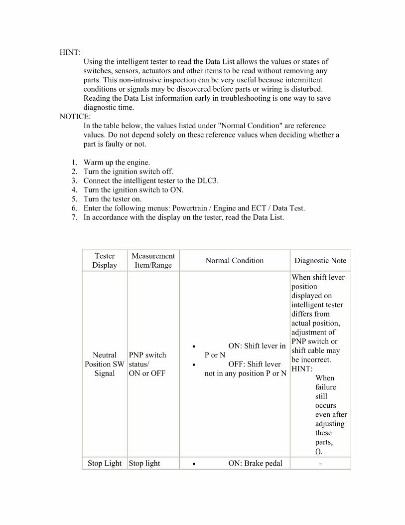
HINT: Using the intelligent tester to read the Data List allows the values or states of switches, sensors, actuators and other items to be read without removing any parts. This non-intrusive inspection can be very useful because intermittent conditions or signals may be discovered before parts or wiring is disturbed. Reading the Data List information early in troubleshooting is one way to save diagnostic time.
NOTICE: In the table below, the values listed under "Normal Condition" are reference values. Do not depend solely on these reference values when deciding whether a part is faulty or not.
1. Warm up the engine. 2. Turn the ignition switch off. 3. Connect the intelligent tester to the DLC3. 4. Turn the ignition switch to ON. 5. Turn the tester on. 6. Enter the following menus: Powertrain / Engine and ECT / Data Test. 7. In accordance with the display on the tester, read the Data List.
Tester Display
Measurement Item/Range Normal Condition Diagnostic Note
Neutral Position SW
Signal
PNP switch status/ ON or OFF
• ON: Shift lever in P or N
• OFF: Shift lever not in any position P or N
When shift lever position displayed on intelligent tester differs from actual position, adjustment of PNP switch or shift cable may be incorrect. HINT:
When failure still occurs even after adjusting these parts, ().
Stop Light Stop light • ON: Brake pedal -

Switch switch status/ ON or OFF
is depressed • OFF: Brake pedal
is released
SPD (NT)
Input turbine speed/ display: 50 rpm min.: 0 rpm max.: 12750 rpm
• Lock-up ON (After warming up engine): Input turbine speed (NT) equal to engine speed
• Lock-up OFF (Idling at P or N position): Input turbine speed (NT) nearly equal to engine speed
• Vehicle stopped in R position: 0 rpm
-
Shift SW Status (P Range)
PNP switch status/ ON or OFF
• ON: Shift lever in P
• OFF: Shift lever not in P
When shift lever position displayed on intelligent tester differs from actual position, adjustment of PNP switch or shift cable may be incorrect. HINT:
When failure still occurs even after adjusting these parts, ().
kick Down Switch Status
Kick Down switch status/ ON or OFF
• ON: Accelerator pedal fully depressed
• OFF: Accelerator pedal released
-
Shift SW Status (R
PNP switch status/
• ON: Shift lever in R
When shift lever position

Range) ON or OFF • OFF: Shift lever not in R
Shift SW Status (N Range)
PNP switch status/ ON or OFF
• ON: Shift lever in N
• OFF: Shift lever not in N
Shift SW Status (D Range)
PNP switch status/ ON or OFF
• ON: Shift lever in D
• OFF: Shift lever not in D
displayed on intelligent tester differs from actual position, adjustment of PNP switch or shift cable may be incorrect. HINT:
When failure still occurs even after adjusting these parts, ().
A/T Oil Temperature
1
CVT fluid temperature sensor value/ min.: -40°C (-40°F) max.: 215°C (419°F)
• After stall test; Approx. 80°C (176°F)
• Equal to ambient temperature when cold soak
If value is -40°C (-40°F) or 150°C (302°F) or more, CVT fluid temperature sensor circuit is open or short.
NT Sensor Voltage
Input turbine speed (NT) sensor output voltage/ min,: 0 max,: 4.999
Engine idling speed (Vehicle stopped in shift lever P or N position) Constantly changes between 0.8 to 1.6 V and 2.4 to 3.2 V
-
SD Switch PNP switch status/ ON or OFF
• ON: Shift lever in S
• OFF: Shift lever not in S
Shift SW Status (B Range)
PNP switch status/ ON or OFF
• ON: Shift lever in B
• OFF: Shift lever not in B
When shift lever position displayed on intelligent tester differs from actual position, adjustment of PNP switch or shift cable may be incorrect. HINT:
When failure still

occurs even after adjusting these parts, ().
SPD (NIN)
Primary pulley speed (NIN)/ display: 50 rpm min.: 0 rpm max.: 12750 rpm
• Vehicle stopped: 0 rpm
• Lock up ON (After warming up engine): Primary pulley speed (NIN) equal to engine speed
-
SPD (NOUT)
Secondary pulley speed (NOUT)/ display: 50 rpm min.: 0 rpm max.: 12750 rpm
• Vehicle stopped: 0 rpm
• Vehicle cruising at approx. 60 km/h (37 mph): 2900 rpm
-
NOUT Sensor Voltage
Secondary pulley speed (NOUT) sensor output voltage/ min,: 0 max,: 4.999
Engine idling speed: approx. 2 V -
A/T Oil Pressure
Secondary oil pressure value/min.: -0.625 MPa max.: 9.575 MPa
Secondary oil pressure inspection (D position stall test) 3.81 to 4.58 MPa
-
G sensor
Converted output voltage of yaw rate and acceleration sensor/ min.: 0 V max.: 5 V
Displays converted voltage of yaw rate and acceleration sensor
• Vehicle on level ground: 2.31 V to 2.69 V
• Decelerating: 1.88 V to (2.5) V
• Accelerating: (2.5) V to 3.11 V
-

• G sensor malfunction: set to 1.87 V
• Communication malfunction: set to 1.87 V
Solenoid (DSU)
Lock-up engagement solenoid DSU status/ ON or OFF
• ON: Lock up operating
• OFF: Lock up not operating
-
Lock Up Lock-up/ ON or OFF
• ON: Lock up operating
• OFF: Lock up not operating
-
Lock Up Solenoid
Status
Lock-up solenoid status/ ON or OFF
• Lock-up solenoid ON: ON
• Lock-up solenoid OFF: OFF
-
Shift Status
ECM gearshift command/ 1st, 2nd, 3rd, 4th and 5th
Same as actual gear ratio -
Solenoid (DS2)
Shift control solenoid DS2 status/ ON or OFF
• OFF: Constant cruising with shift lever in D
• ON: Accelerator pedal further depressed
-
Solenoid (DS1)
Shift control solenoid DS1 status/ ON or OFF
• ON: Driving with shift lever in D
• OFF: Accelerator pedal released
-
Solenoid (SLS)
Belt clamping pressure linear solenoid SLS status/ ON or OFF
• ON: After engine start
• OFF: Ignition switch ON
-
G Sensor Calibration
G sensor calibration status/
Complete -

Incomplete or Complete
MIL MIL status/ ON or OFF
Comes on when the ECM detects a malfunction and issues a command to illuminate the MIL
-
#Codes
Number of Codes/ Min.: 0 Max.: 255
- Number of detected DTCs
Check Mode Check mode/ ON or OFF
• ON: Check mode ON
• OFF: Check mode OFF
-
ACTIVE TEST HINT:
Using the intelligent tester to perform Active Tests allows relays, VSVs, actuators and other items to be operated without removing any parts. This non-intrusive functional inspection can be very useful because intermittent operation may be discovered before parts or wiring is disturbed. Performing Active Tests early in troubleshooting is one way to save diagnostic time. Data List information can be displayed while performing Active Tests.
1. Warm up the engine. 2. Turn the ignition switch off. 3. Connect the intelligent tester to the DLC3. 4. Turn the ignition switch to ON. 5. Turn the tester on. 6. Enter the following menus: Powertrain / Engine and ECT / Active Test. 7. In accordance with the display on the tester, perform the Active Test.
Tester Display Test Part Control Range Diagnostic Note
Connect the TC
and TE1 - - -
Activate the Lock
Up
Operate the Lock up ON or OFF
Possible to check Lock up operation HINT:
Perform "Activate

the Lock Up" while monitoring the engine speed (ESPD) and turbine speed (NT).
[Vehicle Condition]
• Vehicle speed: 40 km/h (25 mph) or more
Activate the
Solenoid (SL)
Operate the lock up solenoid SL
Possible to switch shift solenoid SL between minimum current and maximum current
[Vehicle Condition]
• Engine stopped
• Shift lever in P or N
Control the Shift Position
Operates the shift solenoid valves to allow gear ratio to be manually selected [1st - 2nd - 3rd - 4th - 5th] Reference gear ratios: 1st (2.4) - 2nd (1.4) - 3rd (1.0) - 4th (0.7) - 5th (0.43)
• Press "→" button: Shift up
• Press "←" button: Shift down
Used to check the operation of the shift solenoid valves. NOTICE:
Performing this test at speeds other than those specified in "Vehicle Condition" will damage the transaxle.
[Vehicle Condition] 20 km/h (11 mph) or more and 45 km/h (24 mph) or less
Activate the
Solenoid (DSU)
Operate the lock up engagement solenoid DSU
Possible to switch solenoid DSU between 100% and 0%
[Vehicle Condition]
• Engine stopped
• Shift lever in P or N
Activate the
Solenoid (DS1)
Operate the shift solenoid DS1 ON or OFF
[Vehicle Condition]
• Engine stopped
• Shift lever in

P or N
Activate the
Solenoid (DS2)
Operate the shift solenoid DS2 ON or OFF
[Vehicle Condition]
• Engine stopped
• Shift lever in P or N
Control the SLS Pressure
Operate the belt clamping pressure linear solenoid SLS
Possible to switch pressure linear solenoid (SLS) between high pressure and low pressure
[Vehicle Condition]
• Engine stopped
Activate the
Solenoid (SLS)
Operate the belt clamping pressure linear solenoid SLS
Possible to switch pressure linear solenoid SLS between 0% and 100%
[Vehicle Condition]
• Engine stopped
• Shift lever in P or N

CONTINUOUSLY VARIABLE TRANSAXLE FLUID > ADJUSTMENT NOTICE:
• This transmission requires Toyota Genuine CVT Fluid TC. • Make sure that the vehicle is level when inspecting the fluid level.
(The front-to-rear inclination angle must be within +/- 1° from horizontal.) • Allow the fluid to cool to room temperature before performing any of these
procedures.
1. ADD CVT FLUID HINT:
Refer to the following diagram when adding fluid.

1. When adding fluid (large fill volume) *1
1. Be sure that the vehicle remains level and lift the vehicle.

2. Use a socket hexagon wrench (6 mm) to remove the drain plug and gasket.
3. Use a socket hexagon wrench (6 mm) to check that the No. 1 transmission oil filler tube is tightened to the specified torque.
Text in Illustration
*1 No. 1 Transmission Oil Filler Tube
4. Torque: 5. 0.8 N*m 8.2 kgf*cm , 7 in.*lbf
6. NOTICE: 7. If the No. 1 transmission oil filler tube is not tightened to the specified
torque, then the fluid level cannot be adjusted correctly. 8.

9. Remove the refill plug and gasket.
10. Add fluid into the refill hole until it flows out from the overflow hole.

NOTICE: This transmission requires Toyota Genuine CVT Fluid TC.
11. Wait until the steady flow slows to a trickle, install a gasket, and temporarily tighten the drain plug with a socket hexagon wrench (6 mm).
HINT: Because the drain plug will be removed again, the gasket can be reused at this time.

12. Fill the specified volume of transmission fluid into the refill hole.
NOTICE: The fill amount varies depending on the procedures being completed.
Reference Capacity:
Related Procedure Fill Volume Transaxle replacement (with a new torque
converter) 1.4 liters (1.48 US qts,
1.23 Imp. qts) Transaxle replacement (when reusing the
torque converter) 0.4 liters (0.42 US qts,
0.35 Imp. qts)
Torque converter replacement 1.6 liters (1.69 US qts, 1.41 Imp. qts)
Torque converter removal/installation 0.4 liters (0.42 US qts, 0.35 Imp. qts)
Oil pan removal/installation (when oil drained)
0.4 liters (0.42 US qts, 0.35 Imp. qts)
Drive shaft removal/installation 0.4 liters (0.42 US qts, 0.35 Imp. qts)

13. Install the gasket and temporarily tighten the refill plug.
HINT: Because the refill plug will be removed again, the gasket can be reused at this time.
14. Lower the vehicle.
2. When refilling (small fill volume) *2
1. Be sure that the vehicle remains level and lift the vehicle. 2. Remove the refill plug and gasket.

3. Fill the specified volume of transmission fluid into the refill hole.
Reference Capacity:
Related Procedure Fill Volume Oil cooler removal/installation or
replacement 0.4 liters (0.42 US qts, 0.35
Imp. qts)
Repair of oil seeping or oozing 0.4 liters (0.42 US qts, 0.35 Imp. qts)

4. Install the gasket and temporarily tighten the refill plug.
HINT: Because the refill plug will be removed again, the gasket can be reused at this time.
5. Lower the vehicle.
2. FLUID TEMPERATURE CHECK NOTICE:
The fluid temperature can be confirmed by checking the indicator light in the meter or by using the intelligent tester. When using the intelligent tester, it is necessary to change to temperature detection mode in order to idle the vehicle appropriately.
1. When using the intelligent tester
1. Turn the ignition switch off. 2. Connect the intelligent tester to the DLC3. 3. Turn the ignition switch to ON. 4. Turn the tester on. 5. Enter the following menus: Powertrain / Engine and ECT / Data Test /
A/T Oil Temperature 1. 6. Enter the following menus: Powertrain / Engine and ECT / Active Test /
Connect the TC and TE1.

2. When not using the intelligent tester
1. Using SST, connect terminals 13 (TC) and 4 (CG) of the DLC3.
3. Start the engine.
NOTICE: Check that electrical systems such as the air conditioning system, audio system and lighting system are off. HINT: Indicator lights of the meter blink to output DTCs when terminals TC and CG are connected.
4. Slowly move the shift lever from P to B and back to P again.
HINT: Hold the shift lever in each position for about 3 seconds.

5. Move the shift lever to D, and then continuously move the shift lever back and forth between N and D at a rate of 1 shift/1.5 seconds or faster for 6 seconds or more. This will activate the fluid temperature detection mode.
Standard condition: The indicator light (D) remains illuminated for 2 seconds and then turns off.
6. Return the shift lever to P.
7. The indicator light (D) remains off, illuminates, or blinks depending on the fluid temperature.
Indicator Light (D):
Remains OFF Illuminates Blinks
Below 35 °C (95°F) 35 °C (95 °F) to 45 °C (113 °F) 45 °C (113 °F) or higher

Below proper temperature Proper temperature range Above proper temperature
8. If the indicator remains off or illuminates, disconnect the TC terminal and perform the "Fluid Level Check".
NOTICE:
• If the TC terminal is not OFF (open), accurate fluid level adjustment is not possible, so be sure to disconnect this terminal.
• If the TC terminal is not OFF (open), in some cases, the fluid temperature reading will immediately exceed the proper temperature for adjustment.
• If the light is blinking, stop the engine, wait for the fluid temperature to decrease, and repeat the procedure from "Fluid Temperature Check".
3. FLUID LEVEL CHECK
1. Idle the engine to warm it up, and ensure that the fluid temperature is correct.
2. Lift the vehicle immediately after the indicator light (D) illuminates.
NOTICE: Adjust the fluid level while the indicator light (D) is illuminated.

3. Use a socket hexagon wrench (6 mm) to remove the drain plug and gasket, and then check the fluid condition.
HINT:
• Check that the fluid flows out from the overflow tube. • If the volume of fluid that flows out is small, it is possible that fluid was
remaining in the tube (about 5 cc (0.30512 cu in.)), so assume that there was no overflow.
4. If the fluid overflows
1. Wait until the steady flow slows to a trickle, and then use a socket hexagon wrench (6 mm) to install a new gasket and tighten the drain plug.
Torque: 40 N*m 408 kgf*cm , 30 ft.*lbf

2. Replace the refill plug with a new gasket and tighten the refill plug.
Torque: 49 N*m 500 kgf*cm , 36 ft.*lbf
5. If the fluid does not overflow

1. Remove the refill plug and gasket.
2. Add fluid into the refill hole until it flows out from the overflow hole.

NOTICE: This transmission requires Toyota Genuine CVT Fluid TC.
3. Wait until the steady flow slows to a trickle, and then install a new gasket and tighten the drain plug.
Torque: 40 N*m 408 kgf*cm , 30 ft.*lbf

4. Install a new gasket and fully tighten the refill plug.
Torque: 49 N*m 500 kgf*cm , 36 ft.*lbf
6. Lower the vehicle.
7. Turn the ignition switch off and disconnect the intelligent tester.
4. INSPECT FOR CONTINUOUSLY VARIABLE TRANSAXLE FLUID LEAK
1. Clean the area and check for fluid leaks.

CONTINUOUSLY VARIABLE TRANSAXLE ASSEMBLY > COMPONENTS


1 / 3

2 / 3


3 / 3
CONTINUOUSLY VARIABLE TRANSAXLE ASSEMBLY > REMOVAL

1. REMOVE ENGINE ASSEMBLY WITH TRANSAXLE
1. Remove the engine assembly with transaxle ().
2. REMOVE MANIFOLD STAY
1. Remove the 2 bolts, the nut and the manifold stay.
3. REMOVE AIR FUEL RATIO SENSOR

1. Disconnect the wire harness clamp and air fuel ratio sensor connector.
2. Using SST, remove the air fuel ratio sensor from the exhaust manifold.
SST 09224-00010
4. REMOVE NO. 1 EXHAUST MANIFOLD HEAT INSULATOR

1. Remove the 3 bolts and the No. 1 exhaust manifold heat insulator.
5. REMOVE EXHAUST MANIFOLD
1. Remove the 2 bolts, the 4 nuts and the exhaust manifold.

2. Remove the 2 gaskets from the cylinder head.
6. DISCONNECT WATER BY-PASS HOSE ASSEMBLY
1. Disengage the clamp and separate the breather hose from the breather hose clamp.
2. Remove the bolt and separate the water by-pass hose from the CVT.

3. Slide the 2 clamps and separate the 2 water by-pass hoses from the oil cooler.
7. DISCONNECT ENGINE WIRE
1. Disconnect the oil pressure sensor connector and the transmission revolution sensor connector (NOUT).
Text in Illustration

*1 Transmission Revolution Sensor Connector (NOUT)
*2 Oil Pressure Sensor Connector
2. Disengage the 5 clamps and separate the engine wire from the CVT.
3. Remove the bolt and separate the engine wire from the CVT.
Text in Illustration *1 Bolt
4. Disconnect the park/neutral position switch connector, the transmission wire connector, and the 2 transmission revolution sensor connectors (NIN, NT).
Text in Illustration
*2 Park/Neutral Position Switch Connector
*3 Transmission Wire Connector
*4 Transmission Revolution Sensor Connector (NT)
*5 Transmission Revolution Sensor

Connector (NIN)
5. Disengage the 3 clamps and separate the engine wire from the CVT.
8. REMOVE ENGINE MOUNTING CONTROL BRACKET
1. Remove the 4 bolts and then remove the engine mounting control bracket from the CVT.
9. REMOVE STARTER ASSEMBLY

1. Open the terminal cap.
2. Remove the nut and disconnect the terminal 30.
3. Disconnect the connector.
4. Remove the 2 bolts and the starter assembly.
10. REMOVE DRIVE PLATE AND TORQUE CONVERTER SETTING BOLT

1. Use SST to hold the crankshaft pulley in place.
SST 09960-10010 (09962-01000, 09963-01000)
2. Remove the 6 drive plate and torque converter setting bolts.
11. REMOVE CONTINUOUSLY VARIABLE TRANSAXLE

1. Remove the 9 bolts and the CVT.
NOTICE: Do not twist the CVT when removing it from the engine, because the knock pins could be damaged.
12. REMOVE ENGINE MOUNTING STAY LH
1. Remove the 2 bolts and then remove the engine mounting stay LH from the CVT and engine mounting bracket LH.

13. REMOVE ENGINE MOUNTING BRACKET LH
1. Remove the 3 bolts and then remove the engine mounting bracket LH from the CVT.
14. REMOVE NO. 1 TRANSMISSION CONTROL CABLE BRACKET
1. Remove the 2 bolts and then remove the No. 1 transmission control cable bracket from the CVT.

15. REMOVE WIRE HARNESS CLAMP BRACKET
1. Remove the 2 bolts and then remove the 2 wire harness clamp brackets from the CVT.

2. Remove the 3 bolts and then remove the 3 wire harness clamp brackets from the CVT.
16. REMOVE TORQUE CONVERTER ASSEMBLY
1. Remove the torque converter assembly from the CVT.
17. REMOVE CVT OIL PUMP TYPE T OIL SEAL NOTICE:
• Do not remove the front oil pump assembly from the CVT main body, as there is the possibility of the entry of dust and foreign matter.
• Clean the work area, the tools to be used, and other equipment, etc. thoroughly before the operation, as there is the possibility that a CVT malfunction, which could prevent the vehicle from running, could occur if dust or fine foreign matter enters the CVT.
• Do not use cotton work gloves, cloths, or paper towels, etc. that may produce lint, etc.
• Perform the operation as quickly as possible, as dust and foreign matter could enter the CVT while the torque convertor is not attached to it.
• Do not use the air gun until the torque convertor has been installed, as it could cause dust and foreign matter to be stirred up.

1. Clean the tips of both the claws of the SST and the center bolt.
2. Using the SST, remove the CVT oil pump type T oil seal.
SST 09308-10010 NOTICE: Pay attention to the angle of the claws when opening them, and ensure that they do not come into contact with the oil pump housing, as there is the possibility that metal particles could be produced if they do.
18. INSPECT TORQUE CONVERTER
1. Inspect the torque converter one-way clutch.

1. Lightly rotate the stator by pushing the splines with a finger.
Text in Illustration *1 Splines
2. OK: 3. Stator rotates smoothly when turned clockwise and there is resistance
when it is turned counterclockwise.
2. Determine the condition of the torque converter.

1. Replace the torque converter if it does not fulfill any of the standard conditions.
Standard conditions: *During the stall test or when the shift lever is in N, no metallic sounds are emitted from the torque converter. *The one-way clutch rotates smoothly when turned clockwise and does not rotate when turned counterclockwise. *The amount of particulate in the fluid is not greater than the sample shown in the illustration.
Text in Illustration
*1 Sample Showing Maximum Allowable Amount of Particulate in Fluid
*2 Actual Size HINT:
The sample illustration shows approximately 0.025 liters (0.026 US qts, 0.022 Imp. qts) of fluid taken from a removed torque converter clutch.
3. Replace the fluid in the torque converter.
1. If the fluid is discolored and/or has a foul odor, stir the fluid in the torque converter thoroughly and drain the fluid with the torque converter facing upward.
4. Check that the inside of the oil cooler is clean.

1. When inspecting the torque converter and/or replacing fluid, drain the fluid with the oil cooler installation surface facing downward.
HINT: If there is a large amount of particulate in the fluid, clean the inside of the oil cooler by adding new fluid.
2. If the fluid is cloudy or white, check the oil cooler.
5. Check the torque converter installation bolts.
1. All of the installation bolts must be the same length (+/- 0.5 mm (0.0197 in.)) and each must have a spring washer.
19. INSPECT DRIVE PLATE AND RING GEAR
1. Visually check the drive plate and ring gear.
1. Check the drive plate and ring gear for damage.
HINT: Replace the drive plate and ring gear if it is damaged.
2. Inspect runout of drive plate and ring gear.

1. Set up a dial indicator and measure the runout of the drive plate and ring gear at 6 places along the torque converter installation surface.
Text in Illustration *1 Measuring Point
2. Maximum runout: 3. 0.30 mm (0.0118 in.)
4. HINT: 5. If the runout exceeds the maximum, replace the drive plate and ring gear.

CONTINUOUSLY VARIABLE TRANSAXLE ASSEMBLY > INSTALLATION 1. INSTALL TRANSMISSION CASE PLUG ASSEMBLY HINT:
After replacing the CVT, perform the following procedure.
1. Apply Toyota Genuine CVT Fluid TC to the O-ring on a new transmission case plug.
2. Install the transmission case plug onto the CVT.

2. INSTALL WIRE HARNESS CLAMP BRACKET
1. Use the 3 bolts to install the 3 wire harness clamp brackets to the CVT.
Torque: *1: 29 N*m 296 kgf*cm , 21 ft.*lbf *2: 13 N*m 133 kgf*cm , 10 ft.*lbf

2. Use the 2 bolts to install the 2 wire harness clamp brackets to the CVT.
Torque: 13 N*m 133 kgf*cm , 10 ft.*lbf
3. INSTALL NO. 1 TRANSMISSION CONTROL CABLE BRACKET
1. Install the No. 1 transmission control cable bracket onto the CVT with the 2 bolts.
Torque: 12 N*m 122 kgf*cm , 9 ft.*lbf
4. INSTALL ENGINE MOUNTING BRACKET LH

1. Clean and degrease the bolts and the installation holes in the engine mounting bracket LH.
2. Apply adhesive to 2 or 3 threads on the ends of the 3 bolts.
Text in Illustration *1 Adhesive
3. Adhesive: 4. Toyota Genuine Adhesive 1324, Three Bond 1324 or equivalent
3. Install the engine mounting bracket LH onto the CVT with the 3 bolts.
Torque: 64 N*m 653 kgf*cm , 47 ft.*lbf HINT:

*1 (Temporarily tighten) → *2 (Fully tighten) → *3 (Fully tighten) → *1 (Fully tighten)
5. INSTALL ENGINE MOUNTING STAY LH
1. Install the engine mounting stay LH onto the CVT and engine mounting bracket LH with the 2 bolts.
Torque: 64 N*m 653 kgf*cm , 47 ft.*lbf HINT: *4 (Temporarily tighten) → *5 (Fully tighten) → *4 (Fully tighten)
6. INSTALL CVT OIL PUMP TYPE T OIL SEAL
1. Ensure that there is no dirt or foreign matter on your hands, and then apply genuine TOYOTA MP grease No.2 to the entire periphery of the lip of a new CVT oil pump type T oil seal.
2. Temporarily attach the CVT oil pump type T oil seal by pressing it onto the installation surface of the oil pump housing manually.
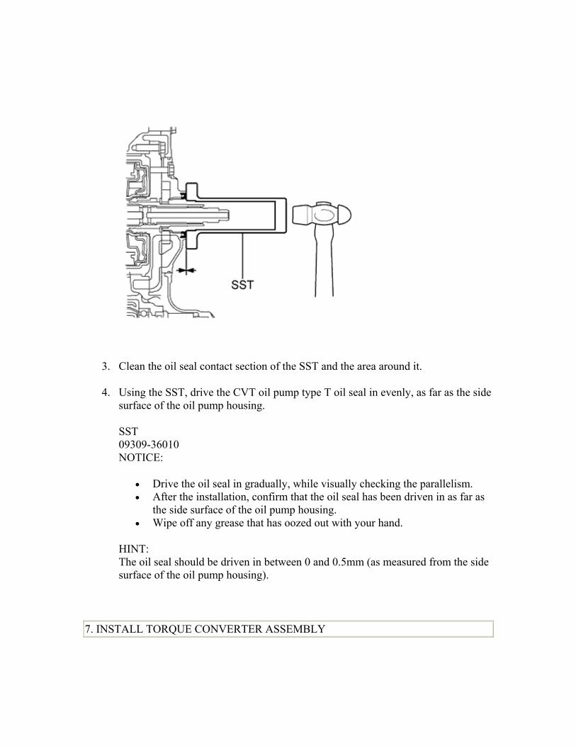
3. Clean the oil seal contact section of the SST and the area around it.
4. Using the SST, drive the CVT oil pump type T oil seal in evenly, as far as the side surface of the oil pump housing.
SST 09309-36010 NOTICE:
• Drive the oil seal in gradually, while visually checking the parallelism. • After the installation, confirm that the oil seal has been driven in as far as
the side surface of the oil pump housing. • Wipe off any grease that has oozed out with your hand.
HINT: The oil seal should be driven in between 0 and 0.5mm (as measured from the side surface of the oil pump housing).
7. INSTALL TORQUE CONVERTER ASSEMBLY

1. Clean and degrease the 6 holes for the torque converter set bolts.
2. Make a matchmark to indicate the position of the torque converter protrusion (*1).
Text in Illustration *1 Protrusion *2 Matchmark
3. Make a matchmark on the housing to indicate the position of the groove in the front oil pump drive gear.

Text in Illustration *1 Wide Groove *2 Narrow Groove *3 Matchmark
4. NOTICE: 5. Make the housing matchmark at the wide groove. The matchmark position must
be correct to prevent damage.
4. Align the matchmarks on the housing and torque converter and engage the input shaft splines with the turbine runner.
Text in Illustration *1 Matchmark *2 Oil Seal
5. NOTICE: • Maintain the torque converter in a horizontal position when installing the
input shaft. • Be sure to not damage the oil seal.

5. Rotate the torque converter to engage the stator shaft splines with the stator splines.
Text in Illustration *1 Matchmark
6. NOTICE: 7. Maintain the torque converter in a horizontal position when installing the stator
shaft. 8. HINT: 9. Rotate the torque converter about 180 degrees.

6. Rotate the torque converter clockwise until the matchmark aligns with the matchmark on the case, and then engage the grooves in the oil pump drive gear with the claws in the torque converter.
Text in Illustration *1 Matchmark
7. NOTICE: • Maintain the torque converter in a horizontal position when installing the
input shaft and stator shaft. • Do not push the torque converter while aligning the matchmarks.

7. Using a vernier caliper, measure the distance from the CVT fitting surface on the engine to the torque converter fitting surface on the drive plate (dimension A).
Text in Illustration *1 CVT Installation Surface
*2 Torque Converter Installation Surface

8. Using a vernier caliper and a straightedge, measure the distance from the set block to the housing end (dimension B) and check that dimension B is greater than dimension A.
Standard distance: B=A+1 mm (0.0394 in.) or more NOTICE: Ensure that the torque converter is inserted all the way into the CVT. If the converter is not inserted sufficiently when the CVT is installed onto the engine, the CVT and torque converter could be damaged.
8. INSTALL CONTINUOUSLY VARIABLE TRANSAXLE

1. Confirm that 2 knock pins are on the transaxle contact surface of the engine cylinder block before transaxle installation.
Text in Illustration *1 Knock Pin
2. Apply clutch spline grease to the round of the crankshaft contact surface (*3) with the torque converter centerpiece.
Text in Illustration *2 Crankshaft
3. Clutch spline grease: 4. Toyota Genuine Clutch Spline Grease or equivalent 5. Maximum spread: 6. Approximately 1 g (0.353 oz)

3. Maintain the engine and CVT in a horizontal position, align the knock pins and holes*4, and tighten the 9 bolts shown the illustration.
Torque: *1: 64 N*m 653 kgf*cm , 47 ft.*lbf *2: 37 N*m 377 kgf*cm , 27 ft.*lbf *3: 39 N*m 398 kgf*cm , 29 ft.*lbf NOTICE:
• Confirm that there are 2 knock pins on the fitting surface of the engine block before installing the CVT.
• Do not twist or apply excessive force to the CVT. • Check that the torque converter rotates smoothly after installation of the
CVT.
HINT:
Bolt length
• *1: 45 mm (1.77 in.) • *2: 45 mm (1.77 in.) • *3: 35 mm (1.38 in.)

9. INSTALL DRIVE PLATE AND TORQUE CONVERTER SETTING BOLT
1. Clean and degrease the 6 drive plate and torque converter setting bolts.
2. Apply adhesive to 2 or 3 threads on the ends of the 6 torque converter set bolts.
Text in Illustration *1 Adhesive
3. Adhesive: 4. Toyota Genuine Adhesive 1324, Three Bond 1324 or equivalent

3. Use SST to hold the crankshaft pulley in place.
SST 09960-10010 (09962-01000, 09963-01000)
4. Install the 6 torque converter set bolts.
Torque: 28 N*m 286 kgf*cm , 21 ft.*lbf HINT: Tighten the black-colored bolt first, and then tighten the 5 silver-colored bolts.

10. INSTALL STARTER ASSEMBLY
1. Install the starter assembly with the 2 bolts.
Torque: 37 N*m 377 kgf*cm , 27 ft.*lbf
2. Connect the connector.
3. Connect the cable to terminal 30 with the nut.
Torque: 9.8 N*m 100 kgf*cm , 87 in.*lbf
4. Close the terminal cap.
11. INSTALL ENGINE MOUNTING CONTROL BRACKET

1. Install the engine mounting control bracket onto the CVT with the 4 bolts.
Torque: 45 N*m 459 kgf*cm , 33 ft.*lbf HINT: *1 (Temporarily tighten) → *3 (Fully tighten) → *2 (Fully tighten) → *1 (Fully tighten)
12. INSTALL ENGINE WIRE

1. Engage the 3 clamps and install the engine wire to the CVT.
2. Connect the park/neutral position switch connector, the transmission wire connector, and the 2 transmission revolution sensor connectors (NIN, NT).
Text in Illustration
*2 Park/Neutral Position Switch Connector
*3 Transmission Wire Connector
*4 Transmission Revolution Sensor Connector (NT)
*5 Transmission Revolution Sensor Connector (NIN)
3. Install the engine wire onto the CVT with the bolt.
Text in Illustration *1 Bolt
4. Torque: 5. 13 N*m 133 kgf*cm , 10 ft.*lbf

4. Engage the 5 clamps and install the engine wire to the CVT.
Text in Illustration
*1 Transmission Revolution Sensor Connector (NOUT)
*2 Oil Pressure Sensor Connector
5. Connect the oil pressure sensor connector and the transmission revolution sensor (NOUT) connector.
13. INSTALL WATER BY-PASS HOSE ASSEMBLY

1. Connect the 2 water by-pass hoses to the oil cooler with the 2 clamps.
Text in Illustration *1 Rear of Vehicle
2. NOTICE: 3. Securely push the hoses over each pipe fitting on the transmission oil cooler until
the hoses contact the rib on each pipe fitting.
2. Install the water by-pass hose onto the CVT with the bolt.
Torque: 29 N*m 296 kgf*cm , 21 ft.*lbf

3. Engage the clamp and install the breather hose to the breather hose clamp.
Text in Illustration
Paint Mark
4. HINT: • Install the breather hose clamp so that the top end of it overlaps the
painted area. • Install the breather hose clamp so that its protuberance is within the
painted area.
14. INSTALL EXHAUST MANIFOLD

1. Place the 2 new gaskets and install the exhaust manifold, tightening the nuts and bolts in the sequence shown in the illustration.
Torque: 28 N*m 286 kgf*cm , 21 ft.*lbf
15. INSTALL NO. 1 EXHAUST MANIFOLD HEAT INSULATOR
1. Install the No. 1 exhaust manifold heat insulator, tightening the nuts and bolts in the sequence shown in the illustration.

Torque: 8.5 N*m 87 kgf*cm , 75 in.*lbf
16. INSTALL AIR FUEL RATIO SENSOR
1. Using SST, install the air fuel ratio sensor to the exhaust manifold.
SST 09224-00010 Torque: without SST: 44 N*m 449 kgf*cm , 32 ft.*lbf with SST: 40 N*m 408 kgf*cm , 30 ft.*lbf NOTICE:
• The "with SST" torque value is effective when using SST with a fulcrum length of 30 mm (1.18 in.).
• The "with SST" torque value is effective when using a torque wrench with a fulcrum length of 300 mm (11.81 in.) ().
• This torque value is effective when SST is parallel to the torque wrench.
2. Install the wire harness clamp and connect the air fuel ratio sensor connector.

17. INSTALL MANIFOLD STAY
1. After temporarily tightening the manifold stay until the nut is firm against the exhaust manifold, fully tighten the manifold stay to the block with the 2 bolts and then fully tighten the nut on the exhaust manifold side.
Torque: 24 N*m 245 kgf*cm , 18 ft.*lbf
18. INSTALL ENGINE ASSEMBLY WITH TRANSAXLE
1. Install the engine assembly with transaxle ().
19. RESET MEMORY (CVT initialization) NOTICE:
Perform Reset Memory (CVT initialization) when replacing the continuously variable transaxle ().

TORQUE CONVERTER AND DRIVE PLATE > INSPECTION 1. INSPECT TORQUE CONVERTER
1. Inspect the torque converter one-way clutch.

1. Lightly rotate the stator by pushing the splines with a finger.
Text in Illustration *1 Splines
2. OK: 3. Stator rotates smoothly when turned clockwise and there is resistance
when it is turned counterclockwise.
2. Determine the condition of the torque converter.

1. Replace the torque converter if it does not fulfill any of the standard conditions.
Standard conditions: *During the stall test or when the shift lever is in N, no metallic sounds are emitted from the torque converter. *The one-way clutch rotates smoothly when turned clockwise and does not rotate when turned counterclockwise. *The amount of particulate in the fluid is not greater than the sample shown in the illustration.
Text in Illustration
*1 Sample Showing Maximum Allowable Amount of Particulate in Fluid
*2 Actual Size HINT:
The sample illustration shows approximately 0.025 liters (0.026 US qts, 0.022 Imp. qts) of fluid taken from a removed torque converter clutch.
3. Replace the fluid in the torque converter.
1. If the fluid is discolored and/or has a foul odor, stir the fluid in the torque converter thoroughly and drain the fluid with the torque converter facing upward.
4. Check that the inside of the oil cooler is clean.

1. When inspecting the torque converter and/or replacing fluid, drain the fluid with the oil cooler installation surface facing downward.
HINT: If there is a large amount of particulate in the fluid, clean the inside of the oil cooler by adding new fluid.
2. If the fluid is cloudy or white, check the oil cooler.
5. Check the torque converter installation bolts.
1. All of the installation bolts must be the same length (+/- 0.5 mm (0.0197 in.)) and each must have a spring washer.
2. INSPECT DRIVE PLATE AND RING GEAR
1. Visually check the drive plate and ring gear.
1. Check the drive plate and ring gear for damage.
HINT: Replace the drive plate and ring gear if it is damaged.
2. Inspect runout of drive plate and ring gear.

1. Set up a dial indicator and measure the runout of the drive plate and ring gear at 6 places along the torque converter installation surface.
Text in Illustration *1 Measuring Point
2. Maximum runout: 3. 0.30 mm (0.0118 in.)
4. HINT: 5. If the runout exceeds the maximum, replace the drive plate and ring gear.

FRONT DIFFERENTIAL OIL SEAL > COMPONENTS

1 / 1

FRONT DIFFERENTIAL OIL SEAL > REPLACEMENT 1. REMOVE FRONT DRIVE SHAFT ASSEMBLY

1. Remove the front drive shaft assembly ().
2. REMOVE NO. 1 CVT TYPE T OIL SEAL
1. Remove the 2 bolts and then remove the drive shaft bearing bracket from the engine.
2. Using SST, remove the No. 1 CVT type T oil seal.
SST 09308-00010

3. REMOVE NO. 2 CVT TYPE T OIL SEAL
1. Using SST, remove the No. 2 CVT type T oil seal.
SST 09308-00010
4. INSTALL NO. 1 CVT TYPE T OIL SEAL

1. Using SST and a hammer, install a new No. 1 CVT type T oil seal.
Text in Illustration *1 Oil Seal Drive-in Depth
2. SST 3. 09309-15020
09950-70010 (09951-07200) 4. Oil seal drive-in depth: 5. 2.6 to 3.6 mm (0.102 to 0.141 in.) (from the end of the case)
2. Apply MP grease to the lip of the No. 1 CVT type T oil seal.

3. Install the drive shaft bearing bracket to the engine with the 2 bolts.
Torque: 64 N*m 650 kgf*cm , 47 ft.*lbf
5. INSTALL NO. 2 CVT TYPE T OIL SEAL
1. Using SST and a hammer, install a new No. 2 CVT type T oil seal.

Text in Illustration *1 Oil Seal Drive-in Depth
2. SST 3. 09387-00010
09950-70010 (09951-07200) 4. Oil seal drive-in depth: 5. 2.6 to 3.6 mm (0.102 to 0.141 in.) (from the end of the case)
2. Apply MP grease to the lip of the No. 2 CVT type T oil seal.
6. INSTALL FRONT DRIVE SHAFT ASSEMBLY
1. Install the front drive shaft assembly ().

OIL PAN > COMPONENTS


1 / 1
OIL PAN > REMOVAL

1. REMOVE NO. 2 ENGINE UNDER COVER
1. Remove the 3 bolts and the engine under cover No. 2.
2. DRAIN CONTINUOUSLY VARIABLE TRANSAXLE FLUID
1. Using a socket hexagon wrench (6 mm), remove the drain plug and gasket and drain the fluid.

2. Using a socket hexagon wrench (6 mm), remove the No. 1 transmission oil filler tube and drain the fluid.
Text in Illustration *1 No. 1 Transmission Oil Filler Tube
3. Using a socket hexagon wrench (6 mm), install the No. 1 transmission oil filler tube.
Text in Illustration *1 No. 1 Transmission Oil Filler Tube
4. Torque: 5. 0.8 N*m 8.2 kgf*cm , 7 in.*lbf

4. Install a gasket and temporarily tighten the drain plug with a socket hexagon wrench (6 mm).
HINT: Because the drain plug will be removed again, the gasket can be reused at this time.
3. REMOVE TRANSAXLE OIL PAN SUB-ASSEMBLY
1. Remove the bolt from the CVT.

2. Remove the 15 bolts and the transaxle oil pan.
3. Remove the transaxle oil pan gasket and 2 oil cleaner magnets from the oil pan.
Text in Illustration *1 Oil Cleaner Magnet
4. NOTICE: • Remove any metal particles and clean sludge from the inside of the oil
pan. • Remove all metal particles from the oil cleaner magnet.

OIL PAN > INSTALLATION 1. INSTALL TRANSAXLE OIL PAN SUB-ASSEMBLY

1. Install the 2 oil cleaner magnets onto the oil pan.
Text in Illustration *1 Oil Cleaner Magnet
2. Install a new transaxle oil pan gasket on the transaxle oil pan.
3. Install the transaxle oil pan with the 15 bolts.
Torque: 7.0 N*m 71 kgf*cm , 62 in.*lbf

4. Install the bolt to the CVT.
Torque: 45 N*m 459 kgf*cm , 33 ft.*lbf
2. ADJUST CONTINUOUSLY VARIABLE TRANSAXLE FLUID
1. Add and adjust the CVT fluid ().
3. INSTALL NO. 2 ENGINE UNDER COVER
1. Install the engine under cover No. 2 with the 3 bolts.

Torque: 5.0 N*m 51 kgf*cm , 44 in.*lbf
OIL COOLER > COMPONENTS

1 / 1

OIL COOLER > REMOVAL 1. DRAIN ENGINE COOLANT

Text in Illustration *1 Water Filler Cap Sub-assembly *3 Radiator Drain Cock Plug *2 Water Inlet Drain Cock Plug - -
CAUTION: To avoid the danger of being burned, do not remove the water filler cap sub-assembly while the engine and assembly are still hot. Thermal expansion will cause hot engine coolant and steam to blow out from the radiator assembly.
1. Loosen the radiator drain cock plug.
HINT: Collect the coolant in a container and dispose of it according to the regulations in your area.
2. Remove the water filler cap sub-assembly.

3. Connect the hose to the water inlet drain cock plug.
Text in Illustration *1 Hose *2 Water Inlet Clip
4. Remove the water inlet clip.
5. Pull out the water inlet drain cock plug.

2. REMOVE FRONT SUSPENSION MEMBER
1. Remove the front suspension member ().
3. REMOVE TRANSMISSION OIL COOLER ASSEMBLY
1. Slide the 2 clamps and separate the 2 water by-pass hoses from the transmission oil cooler.
2. Remove the 3 bolts and then remove the transmission oil cooler from the CVT.
3. Remove the 2 O-rings from the transmission oil cooler.

OIL COOLER > INSTALLATION 1. INSTALL TRANSMISSION OIL COOLER ASSEMBLY

1. Apply Toyota genuine CVT Fluid TC to the 2 new O-rings and install them on the transmission oil cooler.
Text in Illustration *1 Rear of Vehicle
2. Install the transmission oil cooler onto the CVT with the 3 bolts.
Torque: 21 N*m 214 kgf*cm , 15 ft.*lbf
3. Install the 2 water by-pass hoses to the transmission oil cooler with the 2 clamps.
NOTICE: Securely push the hoses over each pipe fitting on the transmission oil cooler until the hoses contact the rib on each pipe fitting.
2. INSTALL FRONT SUSPENSION MEMBER
1. Install the suspension member ().

3. ADD ENGINE COOLANT
1. Tighten the water inlet drain cock plug.
2. Plunge the engine drain cock plug.
3. Install the water inlet clip.
Text in Illustration *1 Water Inlet Clip *2 Hose
4. Disconnect the hose from the water inlet drain cock plug.

5. Slowly fill the radiator with TOYOTA Super Long Life Coolant (SLLC).
Standard Capacity: Item Capacity
for Manual Transaxle
4.3 liters (4.5 US qts, 3.8 Imp. qts)
for CVT 4.5 liters (4.8 US qts, 4.0 Imp. qts)
NOTICE: Never use water as a substitute for engine coolant. HINT: TOYOTA vehicles are filled with TOYOTA SLLC at the factory. In order to avoid damage to the engine cooling system and other technical problems, only use TOYOTA SLLC or similar high quality ethylene glycol based non-silicate, non-amine, non-nitrite, non-borate coolant with long-life hybrid organic acid technology (coolant with long-life hybrid organic acid technology is a combination of low phosphates and organic acids).
6. Squeeze the inlet and outlet radiator hoses several times by hand, and then check the level of the coolant. If the coolant level is low, add coolant.
7. Fill the radiator reserve tank with coolant to the FULL level.
Text in Illustration *a FULL Line
8. Install the water filler cap sub-assembly.

9. Start the engine and warm it up.
10. Bleed air from the cooling system.
NOTICE:
• Before starting the engine, turn the A/C switch off. • Adjust the air conditioning temperature setting to MAX (HOT). • Adjust the air conditioning blower setting to LO.
4. Warm up the engine until the thermostat opens. While the thermostat is open, allow the coolant to circulate for several minutes.
HINT: Thermostat opening timing can be determined by squeezing the inlet radiator hose, and sensing vibrations when the engine coolant starts to flow inside the hose.
CAUTION: When squeezing the radiator hoses:
• Wear protective gloves. • Be careful as the radiator hoses are hot. • Keep your hands away from the radiator fan.
11. Stop the engine, and wait until the engine coolant cools down.
12. Remove the water filler cap sub-assembly and check the coolant level. If the coolant level is below the LOW line, repeat all of the procedures above.

13. When the coolant level stops going down, check that the coolant level is between the FULL and LOW lines. If the coolant level is low, add coolant to the reservoir tank FULL line.
Text in Illustration *a FULL Line *b LOW Line
4. ADJUST CONTINUOUSLY VARIABLE TRANSAXLE FLUID
1. Adjust the CVT fluid ().
5. INSPECT FOR ENGINE COOLANT LEAK CAUTION:
To avoid the danger of being burned, do not remove the water filler cap sub-assembly while the engine and radiator assembly are still hot. Thermal expansion will cause hot engine coolant and steam to blow out from the radiator assembly.
1. Fill the radiator assembly with engine coolant, and attach a radiator cap tester.
Text in Illustration *1 Radiator Cap Tester

2. Pump the tester to 118 kPa (1.2 kgf/cm2, 17.1 psi), and then check that the pressure does not drop. If the pressure drops, check the hoses, radiator assembly and water pump assembly for leaks. If there are no signs or traces of external engine coolant leaks, check the heater core, cylinder block and head.
REVOLUTION SENSOR (NT SENSOR) > COMPONENTS

1 / 1

REVOLUTION SENSOR (NT SENSOR) > REMOVAL 1. REMOVE TRANSMISSION REVOLUTION SENSOR (NT SENSOR)

1. Disconnect the transmission revolution sensor connector (NT).
2. Remove the bolt and then remove the transmission revolution sensor (NT) from the CVT.
3. Remove the O-ring from the transmission revolution sensor (NT).

REVOLUTION SENSOR (NT SENSOR) > INSPECTION 1. INSPECT TRANSMISSION REVOLUTION SENSOR (NT SENSOR)
1. Connect the battery into the transmission revolution sensor (NT).

Text in Illustration
*1 Component without harness connected (Transmission Revolution Sensor NT) *3 5 mm Gap or Closer
*2 Ammeter *4 Magnetic Object
2. Wave a magnetic object left and right in front of the transmission revolution sensor tip (5 mm gap or closer) to change the high/low signals while measuring the current.
NOTICE: Make sure to wave the magnetic object during the inspection. Current will not change without waving the magnetic object as indicated by the arrow in the illustration.
3. Measure the current according to the value(s) in the table below.
Standard Current: Tester Connection Condition Specified
Condition Low Signal 4 to 8 mA
1 (NTO) - 2 (NTB) High
Signal 12 to 16 mA
If the current value is not as specified, replace the transmission revolution sensor (NT).

REVOLUTION SENSOR (NT SENSOR) > INSTALLATION 1. INSTALL TRANSMISSION REVOLUTION SENSOR (NT SENSOR)
1. Apply Toyota Genuine CVT Fluid TC to a new O-ring and install it on the transmission revolution sensor (NT).

2. Install the transmission revolution sensor (NT) onto the CVT with the bolt.
Torque: 5.4 N*m 55 kgf*cm , 48 in.*lbf
3. Connect the transmission revolution sensor connector (NT).
2. INSPECT FOR CONTINUOUSLY VARIABLE TRANSAXLE FLUID LEAK
1. Clean the area and check for fluid leaks.

REVOLUTION SENSOR (NIN SENSOR) > COMPONENTS
1 / 1

REVOLUTION SENSOR (NIN SENSOR) > REMOVAL 1. REMOVE TRANSMISSION REVOLUTION SENSOR (NIN SENSOR)

1. Disconnect the transmission revolution sensor connector (NIN).
2. Remove the bolt and then remove the transmission revolution sensor (NIN) from the CVT.
3. Remove the O-ring from the transmission revolution sensor (NIN).

REVOLUTION SENSOR (NIN SENSOR) > INSPECTION 1. INSPECT TRANSMISSION REVOLUTION SENSOR (NIN SENSOR)
1. Measure the resistance according to the value(s) in the table below.
Text in Illustration
*1
Component without harness connected (Transmission Revolution Sensor NIN)
2. Standard Resistance:

Tester Connection Condition Specified
Condition 1 (NIN-) - 2 (NIN+)
20°C (68 °F)
560 to 680 Ω
3. If the resistance value is not as specified, replace the transmission revolution sensor (NIN).
REVOLUTION SENSOR (NIN SENSOR) > INSTALLATION

1. INSTALL TRANSMISSION REVOLUTION SENSOR (NIN SENSOR)
1. Apply Toyota Genuine CVT Fluid TC to a new O-ring and install it on the transmission revolution sensor (NIN).
2. Install the transmission revolution sensor (NIN) onto the CVT with the bolt.
Torque: 5.4 N*m 55 kgf*cm , 48 in.*lbf
3. Connect the transmission revolution sensor connector (NIN).
2. INSPECT FOR CONTINUOUSLY VARIABLE TRANSAXLE FLUID LEAK
1. Clean the area and check for fluid leaks.

REVOLUTION SENSOR (NOUT SENSOR) > COMPONENTS

1 / 1

REVOLUTION SENSOR (NOUT SENSOR) > REMOVAL 1. REMOVE AIR CLEANER AND HOSE

1. Loosen the clip and disconnect the ventilation hose.
Text in Illustration *1 Clamp *2 Guide
2. Loosen the hose clamp and disconnect the air cleaner hose.
3. Disengage the 2 clamps and the 2 guides, and remove the air cleaner cap.
2. REMOVE AIR CLEANER FILTER ELEMENT SUB-ASSEMBLY 3. REMOVE TRANSMISSION REVOLUTION SENSOR (NOUT SENSOR)

1. Disconnect the transmission revolution sensor connector (NOUT).
2. Remove the bolt and then remove the transmission revolution sensor (NOUT) from the CVT.
3. Remove the O-ring from the transmission revolution sensor (NOUT).

REVOLUTION SENSOR (NOUT SENSOR) > INSPECTION 1. INSPECT TRANSMISSION REVOLUTION SENSOR (NOUT SENSOR)
1. Connect the battery into the transmission revolution sensor (NOUT).

Text in Illustration
*1 Component without harness connected (Transmission Revolution Sensor NOUT) *3 5 mm Gap or Closer
*2 Ammeter *4 Magnetic Object
2. Wave a magnetic object left and right in front of the transmission revolution sensor tip (5 mm gap or closer) to change the high/low signals while measuring the current.
NOTICE: Make sure to wave the magnetic object during the inspection. Current will not change without waving the magnetic object as indicated by the arrow in the illustration.
3. Measure the current according to the value(s) in the table below.
Standard Current: Tester Connection Condition Specified
Condition Low Signal 4 to 8 mA
1 (NOTO) - 2 (NOTB) High
Signal 12 to 16 mA
If the current value is not as specified, replace the transmission revolution sensor (NOUT).

REVOLUTION SENSOR (NOUT SENSOR) > INSTALLATION 1. INSTALL TRANSMISSION REVOLUTION SENSOR (NOUT SENSOR)
1. Apply Toyota Genuine CVT Fluid TC to a new O-ring and install it on the transmission revolution sensor (NOUT).

2. Install the transmission revolution sensor (NOUT) onto the CVT with the bolt.
Torque: 5.4 N*m 55 kgf*cm , 48 in.*lbf
3. Connect the transmission revolution sensor connector (NOUT).
2. INSTALL AIR CLEANER FILTER ELEMENT SUB-ASSEMBLY 3. INSTALL AIR CLEANER AND HOSE
1. Align the 2 hinges with the case guide, to insert the case into the groove, and engage the 2 clamps to install the air cleaner cap.
Text in Illustration *1 Clamp *2 Guide

2. Connect the air cleaner hose with the hose clamp.
Torque: 3.0 N*m 31 kgf*cm , 27 in.*lbf HINT: Install the clip as shown in the illustration.
3. Connect the ventilation hose with the clip
HINT: Install the clip as shown in the illustration.
4. INSPECT FOR CONTINUOUSLY VARIABLE TRANSAXLE FLUID LEAK
1. Clean the area and check for fluid leaks.

OIL PRESSURE SENSOR > COMPONENTS

1 / 1
OIL PRESSURE SENSOR > REMOVAL

1. REMOVE FRONT WHEEL LH 2. REMOVE ENGINE UNDER COVER LH
1. Remove the 3 clips and engine under cover LH.
3. REMOVE OIL PRESSURE SENSOR

1. Disconnect the oil pressure sensor connector.
2. Using SST, remove the oil pressure sensor.
SST 09268-46012

OIL PRESSURE SENSOR > INSTALLATION 1. INSTALL OIL PRESSURE SENSOR
1. Coat the oil pressure sensor O-ring with Toyota Genuine CVT Fluid TC.
2. Using SST, install the oil pressure sensor onto the CVT.
SST 09268-46012 Torque: 29 N*m 296 kgf*cm , 21 ft.*lbf
3. Connect the oil pressure sensor connector.
2. INSTALL ENGINE UNDER COVER LH
1. Install the engine under cover LH with the 3 clips.
3. INSTALL FRONT WHEEL LH Torque:
103 N*m 1050 kgf*cm , 76 ft.*lbf

4. INSPECT FOR CONTINUOUSLY VARIABLE TRANSAXLE FLUID LEAK
1. Clean the area and check for fluid leaks.
5. RESET MEMORY (CVT oil pressure calibration) NOTICE:
Perform Reset Memory (CVT oil pressure calibration) when replacing the oil pressure sensor ().

PARK / NEUTRAL POSITION SWITCH > COMPONENTS

1 / 1

PARK / NEUTRAL POSITION SWITCH > ON-VEHICLE INSPECTION

1. INSPECT PARK/NEUTRAL POSITION SWITCH
1. Apply the parking brake and turn the ignition switch to ON.
2. Step on the brake pedal and check that the engine starts when the shift lever is in N or P, but does not start in the other positions.
3. Check that the back-up lights illuminate and the reverse warning buzzer sounds when the shift lever is in R, and that they do not function with the shift lever in the other positions.
PARK / NEUTRAL POSITION

SWITCH > REMOVAL 1. SEPARATE TRANSMISSION CONTROL CABLE ASSEMBLY
1. Move the shift lever to N.
2. Remove the nut and disconnect the transmission control cable from the transmission control shaft lever.
2. REMOVE PARK/NEUTRAL POSITION SWITCH ASSEMBLY

1. Disconnect the park/neutral position switch connector.
2. Remove the nut, the spring washer and the transmission control shaft lever.

3. Bend down the tabs of the nut stopper with a screwdriver and remove the lock nut and the nut stopper.
4. Remove the 2 bolts and the park/neutral position switch.

PARK / NEUTRAL POSITION SWITCH > INSPECTION 1. INSPECT PARK/NEUTRAL POSITION SWITCH

1. Measure the resistance according to the value(s) in the table below.
Text in Illustration
*1 Component without harness connected (Park/Neutral Position Switch)
2. Standard Resistance:
Tester Connection
Shift Lever
Position
Specified Condition
P Below 1 Ω2 (RB) - 6
(PL) Except P 10 kΩ or higher
R Below 1 Ω2 (RB) - 1
(RL) Except R 10 kΩ or higher
N Below 1 Ω2 (RB) - 9
(NL) Except N 10 kΩ or higher
D Below 1 Ω2 (RB) - 7
(DL) Except D 10 kΩ or higher
B Below 1 Ω2 (RB) - 3
(BL) Except B 10 kΩ or higher
N and P Below 1 Ω4 (B) - 5 (L) Except N
and P 10 kΩ or
higher
3. If the resistance value is not as specified, replace the park/neutral position switch.

PARK / NEUTRAL POSITION SWITCH > ADJUSTMENT 1. ADJUST PARK/NEUTRAL POSITION SWITCH

1. Move the shift lever to N.
2. Loosen the 2 bolts on the park/neutral position switch.
3. Move the park/neutral position switch to align the neutral reference line and nut stopper protrusion.
Text in Illustration *1 Nut Stopper Protrusion *2 Neutral Reference Line
4. Tighten the 2 bolts on the park/neutral position switch.
Torque: 5.4 N*m 55 kgf*cm , 48 in.*lbf
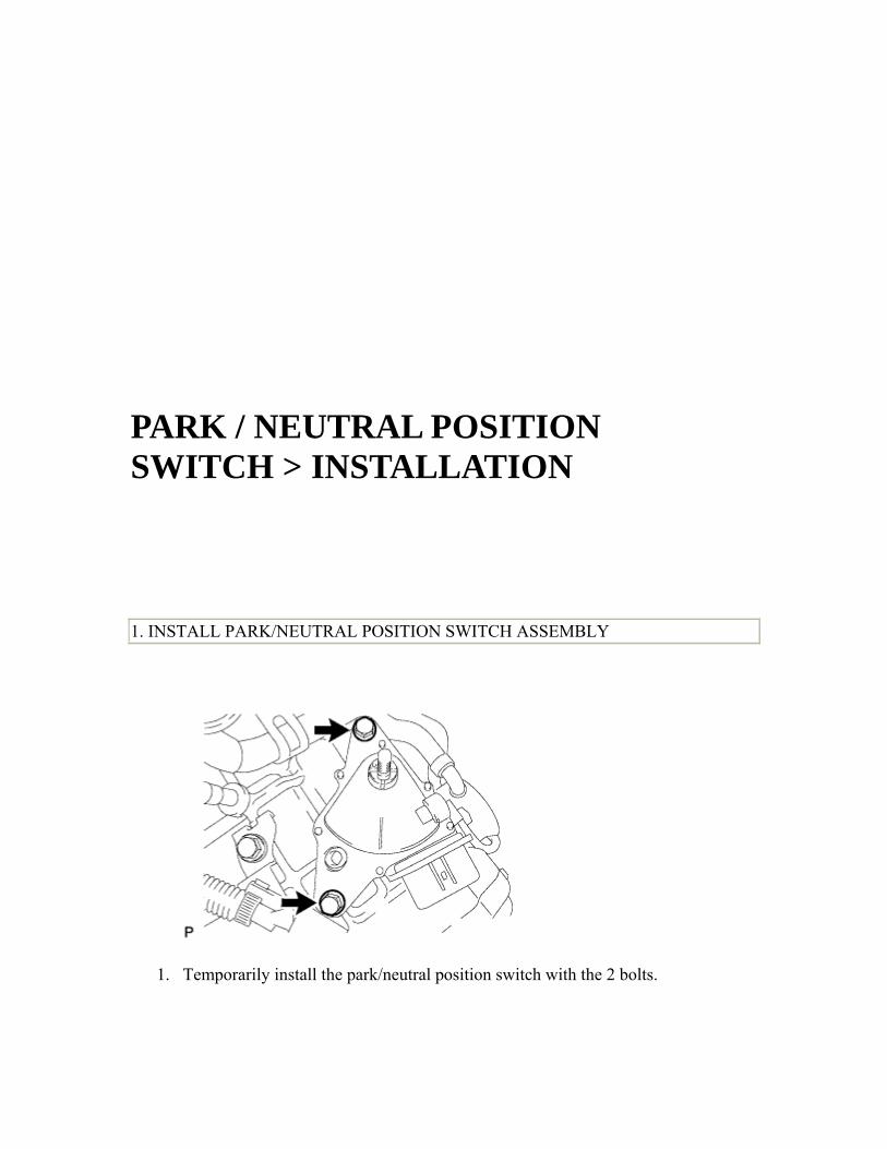
PARK / NEUTRAL POSITION SWITCH > INSTALLATION 1. INSTALL PARK/NEUTRAL POSITION SWITCH ASSEMBLY
1. Temporarily install the park/neutral position switch with the 2 bolts.

2. Install the nut and a new nut stopper.
Torque: 6.9 N*m 70 kgf*cm , 61 in.*lbf
3. Temporarily install the transmission control shaft lever, rotate it counterclockwise until it stops, rotate it clockwise for 2 notches to the N position, and then remove the transmission control shaft lever.

4. Align the neutral reference line with the protrusion on the nut stopper and fully tighten the 2 bolts.
Text in Illustration *1 Nut Stopper Protrusion *2 Neutral Reference Line
5. Torque: 6. 5.4 N*m 55 kgf*cm , 48 in.*lbf
5. Bend the tabs of the nut stopper with a screwdriver.
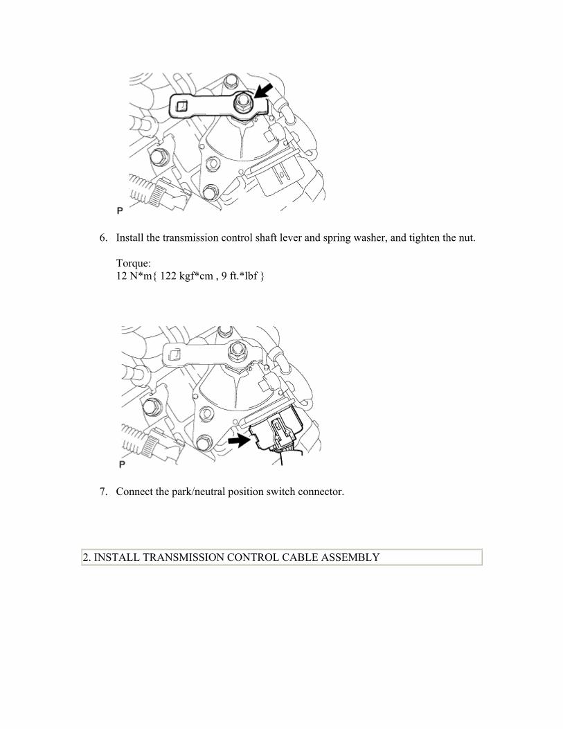
6. Install the transmission control shaft lever and spring washer, and tighten the nut.
Torque: 12 N*m 122 kgf*cm , 9 ft.*lbf
7. Connect the park/neutral position switch connector.
2. INSTALL TRANSMISSION CONTROL CABLE ASSEMBLY

1. Using the nut, connect the transmission control cable to the transmission control shaft lever.
Torque: 12 N*m 122 kgf*cm , 9 ft.*lbf NOTICE: Confirm that the shift lever is in the N position.
3. INSPECT SHIFT LEVER POSITION
1. Turn the ignition switch to ON and step on the brake pedal.
2. Confirm that the shift lever moves smoothly through all of the shift positions and the position indicator shows the correct shift lever position.
3. Start the engine and confirm that the vehicle moves forward when the shift lever is moved from N to D.
4. ADJUST SHIFT LEVER POSITION
1. Remove the console panel upper ().
2. Move the shift lever to N.

3. Slide the adjuster case cover in the direction shown by the arrow.
Text in Illustration *1 Adjuster Case *2 Cover
4. Using a precision screwdriver, pull up the lock piece.
Text in Illustration *3 Lock Piece

5. Press the lock piece into the adjuster case.
Text in Illustration *1 Adjuster Case *2 Lock Piece *3 Cable Rod
6. HINT: 7. Lightly pull the cable rod towards the back of the vehicle to eliminate slack, and
then lock the adjuster.
6. Slide the adjuster case cover in the direction shown by the arrow.
Text in Illustration *1 Adjuster Case *4 Cover
7. NOTICE: 8. If the cover is not pushed over the protrusion on the lock, the cable will not lock
and shift operation will not be accurate.

7. Install the console panel upper ().
TRANSMISSION CONTROL CABLE > COMPONENTS
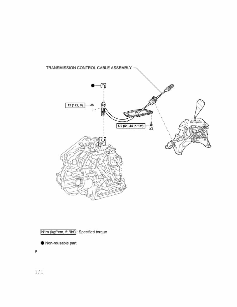
1 / 1

TRANSMISSION CONTROL CABLE > REMOVAL 1. REMOVE REAR CONSOLE BOX ASSEMBLY
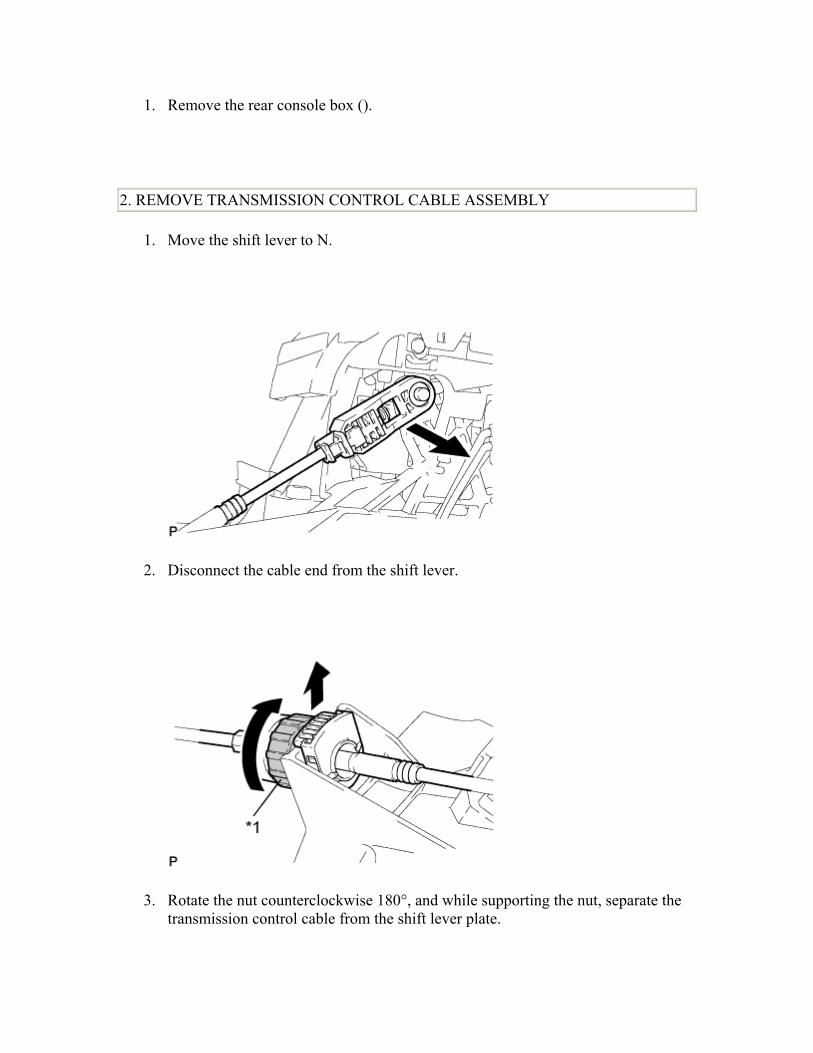
1. Remove the rear console box ().
2. REMOVE TRANSMISSION CONTROL CABLE ASSEMBLY
1. Move the shift lever to N.
2. Disconnect the cable end from the shift lever.
3. Rotate the nut counterclockwise 180°, and while supporting the nut, separate the transmission control cable from the shift lever plate.

Text in Illustration *1 Nut
4. NOTICE: 5. Do not rotate the nut excessively. If the nut is rotated too far, the internal spring
will be damaged and the transmission control cable will be unusable.
4. Remove the nut and disconnect the transmission control cable from the transmission control shaft lever.
5. Remove the clip and separate the transmission control cable from the No. 1 transmission control cable bracket.

6. Remove the 3 bolts and then remove the transmission control cable from the vehicle exterior.

TRANSMISSION CONTROL CABLE > INSTALLATION 1. INSTALL TRANSMISSION CONTROL CABLE ASSEMBLY
1. Pass the transmission control cable into the vehicle and install the transmission control cable to the body, using the 3 bolts.
Torque: 5.0 N*m 51 kgf*cm , 44 in.*lbf

2. Install the transmission control cable to the No. 1 transmission control cable bracket, using a new clip.
3. Using the nut, connect the transmission control cable to the transmission control shaft lever.
Torque: 12 N*m 122 kgf*cm , 9 ft.*lbf NOTICE: Check that the park/neutral position switch is in the N position.

4. Rotate the transmission control cable nut counterclockwise 180° and push in the lock while holding the nut.
Text in Illustration *1 Nut *2 Lock

5. Install the transmission control cable's cable outer onto the shift lever plate.
Text in Illustration *1 Lock *2 Shift Lever Plate
6. NOTICE: 7. After installation, check that the cable outer stopper extends past the line A-A, as
shown in the diagram.
6. Confirm that the shift lever is in N and install the cable end to the shift lever.
NOTICE:
• Push the cable end to the base of the pin to be sure that it is installed securely.
• Install the cable end adjustment mechanism so that the lock faces the driver seat.

2. ADJUST SHIFT LEVER POSITION
1. Remove the console panel upper ().
2. Move the shift lever to N.
3. Slide the adjuster case cover in the direction shown by the arrow.
Text in Illustration *1 Adjuster Case *2 Cover
4. Using a precision screwdriver, pull up the lock piece.

Text in Illustration *3 Lock Piece
5. Press the lock piece into the adjuster case.
Text in Illustration *1 Adjuster Case *2 Lock Piece *3 Cable Rod
6. HINT: 7. Lightly pull the cable rod towards the back of the vehicle to eliminate slack, and
then lock the adjuster.
6. Slide the adjuster case cover in the direction shown by the arrow.
Text in Illustration

*1 Adjuster Case *4 Cover
7. NOTICE: 8. If the cover is not pushed over the protrusion on the lock, the cable will not lock
and shift operation will not be accurate.
7. Install the console panel upper ().
3. INSPECT SHIFT LEVER POSITION
1. Turn the ignition switch to ON and step on the brake pedal.
2. Confirm that the shift lever moves smoothly through all of the shift positions and the position indicator shows the correct shift lever position.
3. Start the engine and confirm that the vehicle moves forward when the shift lever is moved from N to D.
4. INSTALL REAR CONSOLE BOX ASSEMBLY
1. Install the rear console box ().

SHIFT LEVER > COMPONENTS


1 / 1
SHIFT LEVER > ON-VEHICLE INSPECTION

1. INSPECT SHIFT LEVER POSITION
1. Turn the ignition switch to ON and step on the brake pedal.
2. Confirm that the shift lever moves smoothly through all of the shift positions and the position indicator shows the correct shift lever position.
3. Start the engine and confirm that the vehicle moves forward when the shift lever is moved from N to D.
2. INSPECT SHIFT LOCK OPERATION
1. Move the shift lever to P.
2. Turn the ignition switch off.
3. Check that the shift lever cannot be moved from P.
4. Check that the shift lever can be moved from P when the ignition switch is ON and the brake pedal is depressed.
3. INSPECT SHIFT LOCK RELEASE BUTTON OPERATION
1. Move the shift lever to P.
2. Turn the ignition switch off.
3. Press the shift lock release button and check that the shift lever can be moved to any position from P.
4. INSPECT KEY INTERLOCK OPERATION (w/o Smart Access System with Push-button Start)

1. Turn the ignition switch to ON.
2. Step on the brake pedal and check that the shift lever can be moved to any other position from P.
3. Check that the ignition switch cannot be turned to the LOCK position.
4. Move the shift lever to P, rotate the ignition key to the LOCK position, and check that the ignition key can be removed.
SHIFT LEVER > REMOVAL

1. REMOVE REAR CONSOLE BOX ASSEMBLY
1. Remove the rear console box ().
2. DISCONNECT TRANSMISSION CONTROL CABLE ASSEMBLY
1. Move the shift lever to N.
2. Disconnect the cable end from the shift lever.

3. Rotate the nut counterclockwise 180°, and while supporting the nut, separate the transmission control cable from the shift lever plate.
Text in Illustration *1 Nut
4. NOTICE: 5. Do not rotate the nut excessively. If the nut is rotated too far, the internal spring
will be damaged and the transmission control cable will be unusable. 3. REMOVE SHIFT LEVER ASSEMBLY

1. Separate the 2 connectors from the shift lever.
2. Disengage the 4 clamps and separate the instrument panel wire from the shift lever.

3. Remove the 4 bolts and shift lever.
4. REMOVE SHIFT LEVER KNOB SUB-ASSEMBLY
1. Remove the shift lever knob from the shift lever.

SHIFT LEVER > DISASSEMBLY 1. REMOVE SHIFT LOCK CONTROL ECU SUB-ASSEMBLY

1. Disengage the 3 claws and remove the shift lock control ECU from the shift lever.
2. Separate the shift lock solenoid connector from the shift lock control ECU.
2. REMOVE UPPER POSITION INDICATOR HOUSING

1. Disengage the clamps and separate the transmission control switch connector from the shift lever.
Text in Illustration
*1 Transmission Control Switch Connector
2. Disengage the 7 clamps and separate the position indicator light wire from the shift lever.
3. Using a precision screwdriver, pull out terminals 7 and 14 from the transmission control switch connector.
Text in Illustration
*1 Front View of Wire Harness Connector Transmission Control Switch

4. Disengage the 4 claws and remove the position indicator housing upper from the shift lever.
3. REMOVE POSITION INDICATOR LIGHT GUIDE

1. Disengage the 4 claws and remove the position indicator light guide from the position indicator housing upper.
2. Remove the position indicator light wire from the position indicator light guide.
3. Remove the position indicator light cap from the position indicator light valve.
4. Remove the position indicator light valve from the position indicator light wire.
4. REMOVE CONTROL POSITION INDICATOR PLATE

1. Disengage the claws and remove the position indicator plate from the position indicator housing.
5. REMOVE POSITION INDICATOR SLIDE COVER
1. Remove the position indicator slide cover from the shift lever.
6. REMOVE NO. 2 POSITION INDICATOR SLIDE COVER

1. Remove the No. 2 position indicator slide cover from the position indicator slide cover.
7. REMOVE LOWER POSITION INDICATOR HOUSING
1. Using a small screwdriver, disengage the 4 claws and remove the position indicator housing lower from the shift lever.

SHIFT LEVER > INSPECTION 1. INSPECT SHIFT LOCK CONTROL ECU (w/o Smart Entry and Start System)

1. Measure the voltage according to the value(s) in the table below.
Text in Illustration
*1 Component with harness connected(Shift Lock Control ECU)
2. HINT: 3. Do not disconnect the shift lock control ECU connector. 4. Standard Voltage:
Tester Connection
Switch Condition
Specified Condition
Brake pedal depressed 11 to 14V
4 (STP) - 1 (E) Brake pedal
released Below 1 V
1. Ignition switch ACC
and shift lever in P
Below 1 V
2. Ignition switch ACC
and shift lever not in
P (Within
approx. 1 second)
7.5 to 10.5 V
5 (KLS+) - 1 (E)
3. Ignition switch ACC
and shift lever not in
P
6 to 9 V

(After approx. 1 second) Ignition
switch ACC 11 to 14V
Ignition switch ON 11 to 14V
6 (ACC) - 1 (E)
Ignition switch off Below 1 V
Ignition switch ON 11 to 14 V
8 (IG) - 1 (E) Ignition
switch off Below 1 V
5. If the result is not as specified and there are no problems with the wire harness, replace the shift lock control ECU.
2. Measure the resistance according to the value(s) in the table below.
HINT: Do not disconnect the shift lock control ECU connector. Standard Resistance: Tester Connection Condition Specified
Condition
1 (E) - Body ground
When battery voltage not applied
Below 1 Ω
If the result is not as specified and there are no problems with the wire harness, replace the shift lock control ECU.
2. INSPECT SHIFT LOCK CONTROL ECU (w/ Smart Entry and Start System)

1. Measure the voltage according to the value(s) in the table below.
Text in Illustration
*1 Component with harness connected(Shift Lock Control ECU)
2. HINT: 3. Do not disconnect the shift lock control ECU connector. 4. Standard Voltage:
Tester Connection
Switch Condition
Specified Condition
Brake pedal depressed 11 to 14V
6 (STP) - 3 (E) Brake pedal
released Below 1 V
Ignition switch ON 11 to 14V
12 (IG) - 3 (E) Ignition
switch off Below 1 V
5. If the result is not as specified and there are no problems with the wire harness, replace the shift lock control ECU.
2. Measure the resistance according to the value(s) in the table below.
HINT: Do not disconnect the shift lock control ECU connector. Standard Resistance: Tester Connection Condition Specified
Condition

3 (E) - Body ground
When battery voltage not applied
Below 1 Ω
If the result is not as specified and there are no problems with the wire harness, replace the shift lock control ECU.
3. INSPECT TRANSMISSION CONTROL SWITCH
1. Measure the resistance according to the value(s) in the table below when the shift lever is moved to each position.
Text in Illustration
*1 Component without harness connected (Transmission Control Switch)
2. Standard Resistance:
Tester Connection
Shift Lever Position
Specified Condition
D and S Below 1 Ω 1 (NSSD) - 2 (AT3) Except D
and S 10 kΩ or higher
1 (NSSD) - 3 Except D Below 1 Ω

and S (ATD)
D and S 10 kΩ or higher
3. If the result is not as specified, replace the shift lock control unit.
4. INSPECT SHIFT LOCK SOLENOID
1. Disconnect the shift lock solenoid connector of the shift lock ECU.
2. Measure the resistance according to the value(s) in the table below when the shift lever is moved to each position.
Text in Illustration
*1 Component without harness connected (Shift Lock Solenoid)
3. Standard Resistance:
Tester Connection
Shift Lever Position
Specified Condition
P 10 kΩ or higher 4 (P) - 3
(E2) Except P Below 1 Ω
4. If the result is not as specified, replace the shift lock control unit.

3. Measure the resistance according to the value(s) in the table below.
Standard Resistance: Tester Connection Condition Specified
Condition
1 (SLS+) - 2 (SLS-)
When battery voltage not applied
112 Ω
If the result is not as specified, replace the shift lock control unit.
SHIFT LEVER > ADJUSTMENT

1. ADJUST SHIFT LEVER POSITION
1. Remove the console panel upper ().
2. Move the shift lever to N.
3. Slide the adjuster case cover in the direction shown by the arrow.
Text in Illustration *1 Adjuster Case *2 Cover

4. Using a precision screwdriver, pull up the lock piece.
Text in Illustration *3 Lock Piece
5. Press the lock piece into the adjuster case.
Text in Illustration *1 Adjuster Case *2 Lock Piece *3 Cable Rod
6. HINT: 7. Lightly pull the cable rod towards the back of the vehicle to eliminate slack, and
then lock the adjuster.
6. Slide the adjuster case cover in the direction shown by the arrow.

Text in Illustration *1 Adjuster Case *4 Cover
7. NOTICE: 8. If the cover is not pushed over the protrusion on the lock, the cable will not lock
and shift operation will not be accurate.
7. Install the console panel upper ().
SHIFT LEVER > REASSEMBLY

1. INSTALL LOWER POSITION INDICATOR HOUSING
1. Engage the 4 claws and install the position indicator housing lower onto the shift lever.
2. INSTALL NO. 2 POSITION INDICATOR SLIDE COVER
1. Install the No. 2 position indicator slide cover onto the position indicator slide cover.

3. INSTALL POSITION INDICATOR SLIDE COVER
1. Install the position indicator slide cover onto the shift lever.
Text in Illustration *1 Front of Vehicle *2 Arrow on Slide Cover
2. HINT: 3. Install the position indicator slide cover with the arrow facing forward.
4. INSTALL CONTROL POSITION INDICATOR PLATE

1. Engage the claws and install the control position indicator plate onto the position indicator housing.
5. INSTALL POSITION INDICATOR LIGHT GUIDE
1. Install the position indicator light valve onto the position indicator light wire.
2. Install the position indicator light cap onto the position indicator light valve.
3. Install the position indicator light wire onto the position indicator light guide.

4. Engage the 4 claws to install the position indicator light guide onto the position indicator housing upper.
6. INSTALL UPPER POSITION INDICATOR HOUSING

1. Engage the 4 claws and install the position indicator housing upper onto the shift lever.
2. Reinsert the indicator lamp wire into terminals 7 and 14 of the transmission control switch connector.

Text in Illustration
*1 Front View of Wire Harness Connector Transmission Control Switch
3. Engage the 7 clamps and install the position indicator light wire onto the shift lever.
Text in Illustration
*1 Transmission Control Switch Connector
4. Engage the clamp and install the transmission control switch connector onto the shift lever.
7. INSTALL SHIFT LOCK CONTROL ECU SUB-ASSEMBLY

1. Connect the shift lock solenoid connector to the shift lock control ECU.
2. Engage the 3 claws and install the shift lock control ECU onto the shift lever.

SHIFT LEVER > INSTALLATION 1. INSTALL SHIFT LEVER KNOB SUB-ASSEMBLY
1. Install the shift lever knob onto the shift lever.
2. INSTALL SHIFT LEVER ASSEMBLY

1. Install the shift lever with the 4 bolts.
Torque: 12 N*m 122 kgf*cm , 9 ft.*lbf NOTICE: Make sure that the instrument panel wire is not caught under the shift lever.

2. Engage the 4 clamps and install the instrument panel wire onto the shift lever.
3. Connect the 2 connectors to the shift lever.
3. INSTALL TRANSMISSION CONTROL CABLE ASSEMBLY

1. Rotate the transmission control cable nut counterclockwise 180° and push in the lock while holding the nut.
Text in Illustration *1 Nut *2 Lock

2. Install the transmission control cable's cable outer onto the shift lever plate.
Text in Illustration *1 Lock *2 Shift Lever Plate
3. NOTICE: 4. After installation, check that the cable outer lock extends past the line A-A, as
shown in the diagram.
3. Confirm that the shift lever is in N and install the cable end to the shift lever.
NOTICE:
• Push the cable end to the base of the pin to be sure that it is installed securely.
• Install the cable end adjustment mechanism so that the lock faces the driver seat.

4. INSPECT SHIFT LEVER POSITION
1. Turn the ignition switch to ON and step on the brake pedal.
2. Confirm that the shift lever moves smoothly through all of the shift positions and the position indicator shows the correct shift lever position.
3. Start the engine and confirm that the vehicle moves forward when the shift lever is moved from N to D.
5. ADJUST SHIFT LEVER POSITION
1. Remove the console panel upper ().
2. Move the shift lever to N.

3. Slide the adjuster case cover in the direction shown by the arrow.
Text in Illustration *1 Adjuster Case *2 Cover
4. Using a precision screwdriver, pull up the lock piece.
Text in Illustration *3 Lock Piece

5. Press the lock piece into the adjuster case.
Text in Illustration *1 Adjuster Case *2 Lock Piece *3 Cable Rod
6. HINT: 7. Lightly pull the cable rod towards the back of the vehicle to eliminate slack, and
then lock the adjuster.
6. Slide the adjuster case cover in the direction shown by the arrow.
Text in Illustration *1 Adjuster Case *4 Cover
7. NOTICE: 8. If the cover is not pushed over the protrusion on the lock, the cable will not lock
and shift operation will not be accurate.

7. Install the console panel upper ().
6. INSTALL REAR CONSOLE BOX ASSEMBLY
1. Install the rear console box ().