Group 1 Transmitter-Based Tracking...
31
Group 1 Group 1 Transmitter Transmitter - - Based Tracking Based Tracking System System Paul Allen Paul Allen Lloyd Camposagrado Lloyd Camposagrado Andrew Hepp Andrew Hepp Joo Yun Son Joo Yun Son April 21, 2004 April 21, 2004 Rensselaer Polytechnic Rensselaer Polytechnic Institute Institute
Transcript of Group 1 Transmitter-Based Tracking...

Group 1Group 1
TransmitterTransmitter--Based Tracking Based Tracking SystemSystem
Paul Allen Paul Allen Lloyd CamposagradoLloyd CamposagradoAndrew HeppAndrew HeppJoo Yun SonJoo Yun SonApril 21, 2004April 21, 2004Rensselaer Polytechnic Rensselaer Polytechnic InstituteInstitute

MOTIVATIONMOTIVATION
WHOWHO–– Sport RecreationSport Recreation–– Home SafetyHome Safety–– National SafetyNational Safety
WHYWHY–– Accurate tracking of a moving ballAccurate tracking of a moving ball–– To have a versatile tracking system using RF To have a versatile tracking system using RF
technologytechnology

PROJECT GOAL AND APPROACHPROJECT GOAL AND APPROACH
GOALGOAL–– To successfully build a pan and tilt mechanism that will track aTo successfully build a pan and tilt mechanism that will track an object n object
in 3D space using RF technologyin 3D space using RF technology
APPROACHAPPROACH–– Signal strength meters will receive a signal from a transmitterSignal strength meters will receive a signal from a transmitter–– Data from A/D converter will be filtered and convertedData from A/D converter will be filtered and converted–– The controller will accurately move the pan and tiltThe controller will accurately move the pan and tilt

OBJECTIVESOBJECTIVES
Proof of concept for a video tracking system using RF technologyProof of concept for a video tracking system using RF technology
Six signal strength meters, six amplifiers, one transmitterSix signal strength meters, six amplifiers, one transmitter
10’ x 10’ x 10’ 3D tracking space10’ x 10’ x 10’ 3D tracking space
Use data from signal strength meters to track the object in a smUse data from signal strength meters to track the object in a smooth ooth pattern.pattern.
Automatic cameras at a sporting event that can follow the ball Automatic cameras at a sporting event that can follow the ball smoothly without human interactionsmoothly without human interaction

DESIGN DESIGN STRATEGY
Design Specifications
DAS CONTROLLER
STRATEGYParameter Identification
Compensation
Dynamic model (Plant)
Order parts and build/test sensors and transmitter
Integration with MatLab using A/D converters
Generate distance profile
Build 3D space for testing
Mounting System
Controller Design
Integration
Simulation of data acquisition in MatLab
Preliminary design of signal processing
Forced to modify design to use disturbance field
Open loop verification
Non-linear simulation and Full Control Model
Closed loop verification and Tuning
Rise Time: <0.1 secondsRise Time: <0.1 secondsSettling Time: <0.5secondsSettling Time: <0.5secondsMaximum Percent Overshoot: < 10%Maximum Percent Overshoot: < 10%Torque Saturation: 0.71 NmTorque Saturation: 0.71 NmInternal Gear Ratio: 19.5Internal Gear Ratio: 19.5External Gear Ratio: 4External Gear Ratio: 4Friction IdentificationFriction IdentificationMax speed of ball: 10 ft/sec => 5 rad/secMax speed of ball: 10 ft/sec => 5 rad/secPan Range of: 140 degreesPan Range of: 140 degreesTilt Range of: 130 degreesTilt Range of: 130 degreesCamera Height ~ 3.8ftCamera Height ~ 3.8ftCamera Distance from outer edge of Area Camera Distance from outer edge of Area of Interest ~ 2ftof Interest ~ 2ft

Design Specifications
DAS CONTROLLER
Parameter Identification
Compensation
Dynamic model (Plant)
Order parts and build/test sensors and transmitter
Integration with MatLab using A/D converters
Generate distance profile
Build 3D space for testing
Mounting System
Controller Design
Integration
Simulation of data acquisition in MatLab
Preliminary design of signal processing
Forced to modify design to use disturbance field
Open loop verification
Non-linear simulation and Full Control Model
Closed loop verification and Tuning

Simulation of data acquisition in MatLab
Preliminary design of signal processing

Simulation of data acquisition in MatLab
Preliminary design of signal processing
The signal plots to the right show the The signal plots to the right show the three strongest signals from the six three strongest signals from the six signal strength meterssignal strength meters

Design Specifications
DAS CONTROLLER
Parameter Identification
Compensation
Dynamic model (Plant)
Order parts and build/test sensors and transmitter
Integration with MatLab using A/D converters
Generate distance profile
Build 3D space for testing
Mounting System
Controller Design
Integration
Simulation of data acquisition in MatLab
Preliminary design of signal processing
Forced to modify design to use disturbance field
Open loop verification
Non-linear simulation and Full Control Model
Closed loop verification and Tuning

Design SpecificationsIntegrationIntegration–– Connect each sensor to A/D Connect each sensor to A/D
converter via parallel cableconverter via parallel cable–– A/D converter replaces volt A/D converter replaces volt
metermeter
3D space3D space–– Dimensions reduced to 8’ x 8’ x Dimensions reduced to 8’ x 8’ x
8’ due to space constraints8’ due to space constraints–– PVC pipe used for support and PVC pipe used for support and
concealment of wire concealment of wire connectionsconnections
ObstaclesObstacles–– Power supply ground wire Power supply ground wire
acted as an antennaacted as an antenna–– Batteries lose power quickly for Batteries lose power quickly for
any type of reliabilityany type of reliability–– Inconsistent parts created Inconsistent parts created
different signal readingsdifferent signal readings
SolutionsSolutions–– Further reduced dimensions to Further reduced dimensions to
a 2D 8’ x 4’ rectangle (YZ a 2D 8’ x 4’ rectangle (YZ plane)
DAS CONTROLLER
Parameter Identification
Compensation
Dynamic model (Plant)
Order parts and build/test sensors and transmitter
Integration with MatLab using A/D converters
Generate distance profile
Build 3D space for testing
Mounting System
Controller Design
Integration
Simulation of data acquisition in MatLab
Preliminary design of signal processing
Forced to modify design to use disturbance field
Open loop verification
Non-linear simulation and Full Control Model
Closed loop verification and Tuning
plane)

Design Specifications
DAS CONTROLLERSplit distance profile at max and min Split distance profile at max and min to ensure 5 sections of nonto ensure 5 sections of non--repeating repeating valuesvalues
Used velocity direction to identify up Used velocity direction to identify up coming sectioncoming section
Not successful due to change in Not successful due to change in distance profile with reflections and distance profile with reflections and diminishing battery powerdiminishing battery power
Parameter Identification
Compensation
Dynamic model (Plant)
Order parts and build/test sensors and transmitter
Integration with MatLab using A/D converters
Generate distance profile
Build 3D space for testing
Mounting System
Controller Design
Integration
Simulation of data acquisition in MatLab
Preliminary design of signal processing
Open loop verification
Non-linear simulation and Full Control Model
Closed loop verification and Tuning
Forced to modify design to use disturbance field

Design Specifications
DAS CONTROLLER
Parameter Identification
Compensation
Dynamic model (Plant)
Order parts and build/test sensors and transmitter
Integration with MatLab using A/D converters
Generate distance profile
Build 3D space for testing
Mounting System
Controller Design
Integration
Simulation of data acquisition in MatLab
Preliminary design of signal processing
Sensors used for proximity Sensors used for proximity instead of triangulationinstead of triangulation
The threshold voltage is set to The threshold voltage is set to represent a close proximity for represent a close proximity for each sensoreach sensor
YZ coordinates are associated YZ coordinates are associated with each sensor in the 2D planewith each sensor in the 2D plane
When the proximity field is When the proximity field is disturbed, the output of the DAS disturbed, the output of the DAS are the coordinates of the are the coordinates of the corresponding sensor.
Forced to modify design to use disturbance field
Open loop verification
Non-linear simulation and Full Control Model
Closed loop verification and Tuning
corresponding sensor.
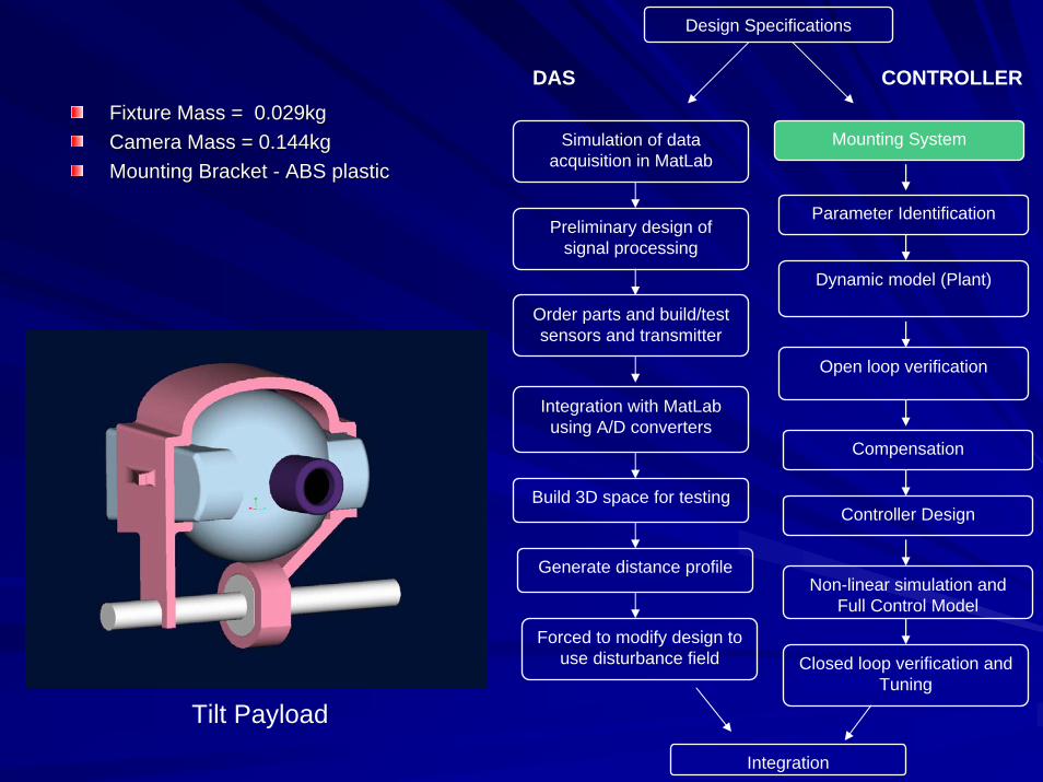
Design Specifications
DAS CONTROLLER
Fixture Mass = 0.029kgFixture Mass = 0.029kgCamera Mass = 0.144kgCamera Mass = 0.144kgMounting Bracket Mounting Bracket -- ABS plastic
Parameter Identification
Compensation
Dynamic model (Plant)
Order parts and build/test sensors and transmitter
Integration with MatLab using A/D converters
Generate distance profile
Build 3D space for testing
Mounting System
Controller Design
Integration
Simulation of data acquisition in MatLab
Preliminary design of signal processing
ABS plastic
Forced to modify design to use disturbance field
Open loop verification
Non-linear simulation and Full Control Model
Closed loop verification and Tuning
Tilt Payload

Design Specifications
DAS CONTROLLER
Parameter Identification
Compensation
Dynamic model (Plant)
Order parts and build/test sensors and transmitter
Integration with MatLab using A/D converters
Generate distance profile
Build 3D space for testing
Mounting System
Controller Design
Integration
Simulation of data acquisition in MatLab
Preliminary design of signal processing
Tilt Motor Tilt Motor –– Coulomb FrictionCoulomb Friction–– Viscous FrictionViscous Friction–– InertiaInertia
Pan MotorPan Motor–– Coulomb FrictionCoulomb Friction–– Viscous FrictionViscous Friction–– Inertia
Forced to modify design to use disturbance field
Open loop verification
Inertia
Non-linear simulation and Full Control Model
Closed loop verification and Tuning

Parameter Identification
Pan Motor Pan Motor –– Coulomb FrictionCoulomb Friction
Positive: 1.9594 VPositive: 1.9594 VNegative: 1.9594 VNegative: 1.9594 V
–– Viscous Friction: 0.0342 VS/radViscous Friction: 0.0342 VS/rad–– Internal Inertia: 9.2 eInternal Inertia: 9.2 e--7 Kg*m^27 Kg*m^2
Tilt MotorTilt Motor–– Coulomb FrictionCoulomb Friction
Positive: 1.3999 VoltsPositive: 1.3999 VoltsNegative: 1.3261 VoltsNegative: 1.3261 Volts
–– Viscous Friction: 0.0285 VS/radViscous Friction: 0.0285 VS/rad–– Internal Inertia: 9.2 eInternal Inertia: 9.2 e--7 Kg*m^27 Kg*m^2
(Coulomb Frictions converted to torque using (Coulomb Frictions converted to torque using K*Nm*A/V)K*Nm*A/V)
Tilt payload (Camera + mount + shaft)Tilt payload (Camera + mount + shaft)–– Mass: 0.3571 KgMass: 0.3571 Kg–– Inertia matrix identifiedInertia matrix identified
Mounting Bracket determined Mounting Bracket determined using CADusing CADShaft CAD was provided in Shaft CAD was provided in classclassCamera was represented Camera was represented using a spherical modelusing a spherical model
–– Center of mass (m): [0 0.0152 Center of mass (m): [0 0.0152 0.0220]0.0220]

Design Specifications
DAS CONTROLLER
Parameter Identification
Compensation
Dynamic model (Plant)
Order parts and build/test sensors and transmitter
Integration with MatLab using A/D converters
Generate distance profile
Build 3D space for testing
Mounting System
Controller Design
Integration
Simulation of data acquisition in MatLab
Preliminary design of signal processing
Forced to modify design to use disturbance field
Open loop verification
Basic Equation for Pan and Tilt as Basic Equation for Pan and Tilt as represented in a simulink diagram Non-linear simulation and
Full Control Model
Closed loop verification and Tuning
represented in a simulink diagram

Dynamic model (Plant)
Gain MarginGain Margin–– InfiniteInfinite
Phase MarginPhase Margin–– 8.31 deg at 11.8 8.31 deg at 11.8
rad/secrad/sec

Design Specifications
DAS CONTROLLER
Parameter Identification
Compensation
Dynamic model (Plant)
Order parts and build/test sensors and transmitter
Integration with MatLab using A/D converters
Generate distance profile
Build 3D space for testing
Mounting System
Controller Design
Integration
Simulation of data acquisition in MatLab
Preliminary design of signal processing
Forced to modify design to use disturbance field
Open loop verification
Non-linear simulation and Full Control Model
Closed loop verification and Tuning
To Verify Open loop modelTo Verify Open loop model–– Using a determined input Using a determined input
torque, verify that the simulated torque, verify that the simulated response matches the actual response matches the actual response using constant inputs response using constant inputs and changing inputsand changing inputs
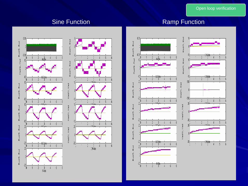
Open loop verification
Sine Function Ramp Function

Design Specifications
DAS CONTROLLER
Parameter Identification
Compensation
Dynamic model (Plant)
Order parts and build/test sensors and transmitter
Integration with MatLab using A/D converters
Generate distance profile
Build 3D space for testing
Mounting System
Controller Design
Integration
Simulation of data acquisition in MatLab
Preliminary design of signal processing
Forced to modify design to use disturbance field
Open loop verification
Non-linear simulation and Full Control Model
Closed loop verification and Tuning

Design Specifications
DAS CONTROLLER
Parameter Identification
Compensation
Dynamic model (Plant)
Order parts and build/test sensors and transmitter
Integration with MatLab using A/D converters
Generate distance profile
Build 3D space for testing
Mounting System
Controller Design
Integration
Simulation of data acquisition in MatLab
Preliminary design of signal processing
For Tilt motor, treat gravity as a For Tilt motor, treat gravity as a disturbancedisturbanceG(s) = k/(sG(s) = k/(s22 + as)+ as)
Forced to modify design to use disturbance field
Open loop verification
Non-linear simulation and Full Control Model
Closed loop verification and Tuning
Linear Plant Model

Controller Design
Based on the desired performance specs, Based on the desired performance specs, the controller parameters can be identifiedthe controller parameters can be identified
–– Natural Frequency Natural Frequency -- WnWn–– Damping ratio Damping ratio -- ZZ
Determine the Determine the KKpp and and KKdd for each controllerfor each controllerSystem is designed to track (it will never System is designed to track (it will never reach steady state), so reach steady state), so KiKi is not necessary is not necessary
Get limits for Get limits for wnwn and zeta on root locus and zeta on root locus diagramdiagram
Design Specifications
DAS CONTROLLER
Parameter Identification
Compensation
Dynamic model (Plant)
Order parts and build/test sensors and transmitter
Integration with MatLab using A/D converters
Generate distance profile
Build 3D space for testing
Mounting System
Controller Design
Integration
Simulation of data acquisition in MatLab
Preliminary design of signal processing
Forced to modify design to use disturbance field
Open loop verification
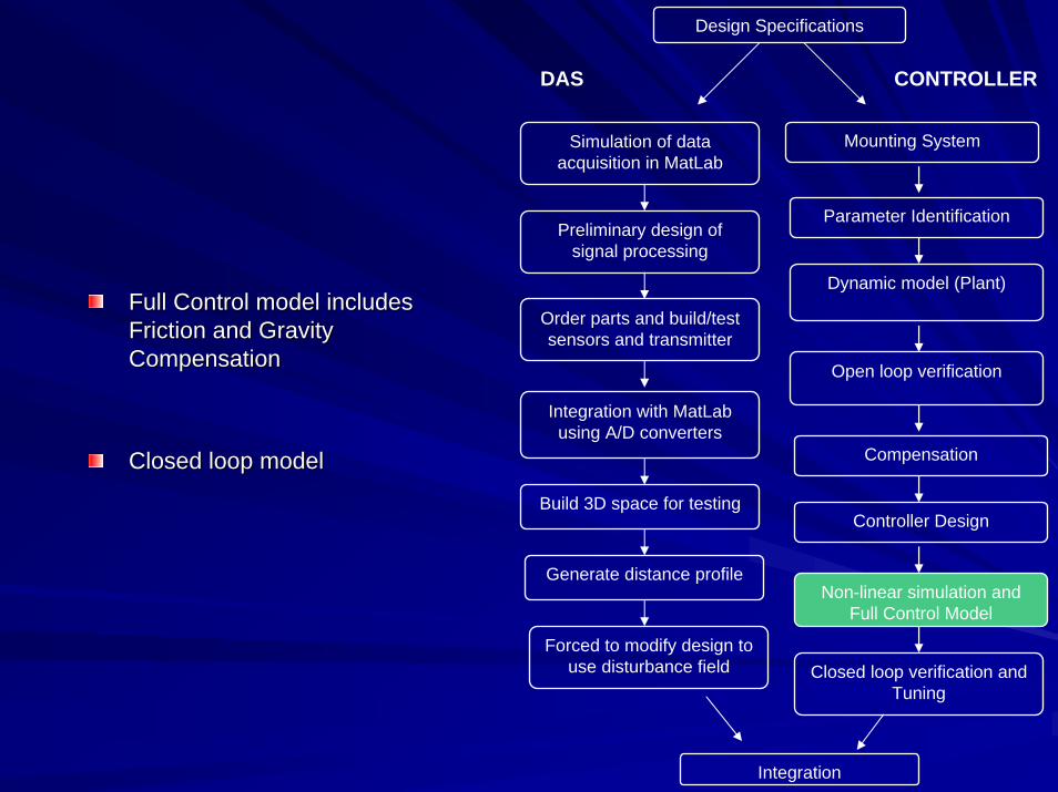
Full Control model includes Full Control model includes Friction and Gravity Friction and Gravity CompensationCompensation
Closed loop modelClosed loop model
Non-linear simulation and Full Control Model
Closed loop verification and Tuning

Non-linear simulation and Full Control Model
ClosedClosed--loop verificationloop verification–– Since we are tracking, all we are worried about is Since we are tracking, all we are worried about is
tracking a moving objecttracking a moving object–– Tracking an object at constant speed which Tracking an object at constant speed which
does not change directiondoes not change direction–– Tracking an object which changes directionTracking an object which changes direction

Design Specifications
DAS CONTROLLER
Parameter Identification
Compensation
Dynamic model (Plant)
Order parts and build/test sensors and transmitter
Integration with MatLab using A/D converters
Generate distance profile
Build 3D space for testing
Mounting System
Controller Design
Integration
Simulation of data acquisition in MatLab
Preliminary design of signal processing
ClosedClosed--loop verificationloop verification–– Since we are tracking, all we are Since we are tracking, all we are
worried about is tracking a moving worried about is tracking a moving objectobject
–– Tracking an object at constant Tracking an object at constant speed which does not change speed which does not change directiondirection
–– Tracking an object which changes Tracking an object which changes directiondirection
TuningTuning–– In order to compensate for real world In order to compensate for real world
dynamics of the Pan and Tilt, we must dynamics of the Pan and Tilt, we must tune the designed controllertune the designed controller
–– This accounts for inaccurate frictional and This accounts for inaccurate frictional and gravitational models
Forced to modify design to use disturbance field
Open loop verification
gravitational models
Non-linear simulation and Full Control Model
Closed loop verification and Tuning

Design Specifications
DAS CONTROLLER
Parameter Identification
Compensation
Dynamic model (Plant)
Order parts and build/test sensors and transmitter
Integration with MatLab using A/D converters
Generate distance profile
Build 3D space for testing
Mounting System
Controller Design
Integration
Simulation of data acquisition in MatLab
Preliminary design of signal processing
The output from the DAS will define The output from the DAS will define the current location of the object in the current location of the object in 33--dimensional Cartesian coordinate dimensional Cartesian coordinate systemsystem
X direction fixed at 0 to X direction fixed at 0 to accommodate problems with accommodate problems with sensors (2D YZ space)sensors (2D YZ space)
The location of the camera can be The location of the camera can be changed dynamicallychanged dynamically
Based on the camera location, the Based on the camera location, the Simulink code will determine the Simulink code will determine the desired anglesdesired angles
3D tracking was tested with 3D tracking was tested with simulation only
Forced to modify design to use disturbance field
Open loop verification
Non-linear simulation and Full Control Model
Closed loop verification and Tuning
simulation only

Integration
Simulation was run and Simulation was run and a 3D linea 3D line--ofof--best fit was best fit was extrapolated from the extrapolated from the data pointsdata points
Variations from the line Variations from the line of curve due to simulated of curve due to simulated noise and triangulation noise and triangulation inaccuraciesinaccuracies

RESULTSRESULTSDESIREDDESIRED
–– Max Speed 10 ft/secMax Speed 10 ft/sec–– Tracking error of 10% ~ 14 Tracking error of 10% ~ 14
degreesdegrees–– Rise time < 0.1 secRise time < 0.1 sec–– Setting Time < 0.5 sec
ACTUALACTUAL–– Max Speed ~ 20 ft/secMax Speed ~ 20 ft/sec–– Tracking error under 5%Tracking error under 5%–– Rise Time ~ 0.063 sec (step Rise Time ~ 0.063 sec (step
response)response)–– Settling Time ~ 0.309 sec Settling Time ~ 0.309 sec
(step response)(step response)Setting Time < 0.5 sec
Using sensors as proximity Using sensors as proximity Camera view Camera view Simulated Movement Simulated Movement

PROJECT ASSESSMENTPROJECT ASSESSMENT
ObjectiveObjective–– RF technology usedRF technology used–– Use six sensors to Use six sensors to
triangulate an objecttriangulate an object–– Smoothly track an Smoothly track an
object in a provided 3D object in a provided 3D space
AssessmentAssessment–– Low cost RF technology Low cost RF technology
is too unpredictable for is too unpredictable for tracking purposestracking purposes
–– Use five sensors to Use five sensors to signal object locationsignal object location
–– Sensors used for Sensors used for proximity in 2D spaceproximity in 2D space
space

CONCLUSIONCONCLUSION
Low cost RF technology is too unpredictable for tracking Low cost RF technology is too unpredictable for tracking purposespurposes–– Signal Strength Meter component variance is too greatSignal Strength Meter component variance is too great–– Reflection are too unpredictableReflection are too unpredictable
RF adequate for proximity detection and field RF adequate for proximity detection and field disturbancedisturbance
Controller designed works well for tracking but was not Controller designed works well for tracking but was not designed with steady state error as a specification so designed with steady state error as a specification so slight jitters occurred during proximity experimentsslight jitters occurred during proximity experiments

QUESTIONS?QUESTIONS?