BALL ON PLATE BALANCING SYSTEM Proposal for...
28
BALL ON PLATE BALANCING SYSTEM Proposal for ECSE-4962 Control Systems Design Greg Andrews Chris Colasuonno Aaron Herrmann February 18, 2004 Rensselaer Polytechnic Institute
-
Upload
truongkien -
Category
Documents
-
view
217 -
download
3
Transcript of BALL ON PLATE BALANCING SYSTEM Proposal for...

BALL ON PLATE BALANCING SYSTEM
Proposal for ECSE-4962 Control Systems Design
Greg AndrewsChris ColasuonnoAaron Herrmann
February 18, 2004
Rensselaer Polytechnic Institute

Abstract
This report describes the proposed design and development strategy for implementing a control system tobalance a ball on a plate. A pan-tilt device is placed on its side so as to create a tilt-tilt mechanism capableof moving a ball within an X-Y plane. A resistive touch pad is placed on the plane to allow the measurementof the location of said ball. Dynamic modeling of this system allows the creation of a digital controllercapable of placing the ball at certain locations or following a preset path. The project goal is to create asystem capable of moving the ball at a rapid rate of speed in any of several predefined complex paths withprecision and accuracy.

Contents
1 Introduction 4
2 Objective 5
3 Design Strategy 63.1 Model Development . . . . . . . . . . . . . . . . . . . . . . . . . . . . . . . . . . . . . . . . . 63.2 Performance Specifications vs. Available Components . . . . . . . . . . . . . . . . . . . . . . 73.3 Parameter Identification . . . . . . . . . . . . . . . . . . . . . . . . . . . . . . . . . . . . . . . 83.4 Simulation . . . . . . . . . . . . . . . . . . . . . . . . . . . . . . . . . . . . . . . . . . . . . . . 83.5 Controller Design and Tuning . . . . . . . . . . . . . . . . . . . . . . . . . . . . . . . . . . . . 113.6 Design Alternatives . . . . . . . . . . . . . . . . . . . . . . . . . . . . . . . . . . . . . . . . . . 113.7 Subsystem Development . . . . . . . . . . . . . . . . . . . . . . . . . . . . . . . . . . . . . . . 12
3.7.1 Touch pad . . . . . . . . . . . . . . . . . . . . . . . . . . . . . . . . . . . . . . . . . . . 123.7.2 Inclinometer . . . . . . . . . . . . . . . . . . . . . . . . . . . . . . . . . . . . . . . . . 12
4 Verification 134.1 Testing Procedure . . . . . . . . . . . . . . . . . . . . . . . . . . . . . . . . . . . . . . . . . . 134.2 Tolerance Analysis . . . . . . . . . . . . . . . . . . . . . . . . . . . . . . . . . . . . . . . . . . 14
5 Cost and Schedule 155.1 Cost Analysis . . . . . . . . . . . . . . . . . . . . . . . . . . . . . . . . . . . . . . . . . . . . . 155.2 Phases . . . . . . . . . . . . . . . . . . . . . . . . . . . . . . . . . . . . . . . . . . . . . . . . . 165.3 Schedule . . . . . . . . . . . . . . . . . . . . . . . . . . . . . . . . . . . . . . . . . . . . . . . . 17
6 Statement of Contribution 20
A Touch pad data sheet 22
B Coordinate System - Body A 24
C Coordinate System - Body B 25
D CAD Model 26
1

List of Figures
3.1 System States . . . . . . . . . . . . . . . . . . . . . . . . . . . . . . . . . . . . . . . . . . . . . 93.2 System States with Initial Conditions . . . . . . . . . . . . . . . . . . . . . . . . . . . . . . . 93.3 Simulation Diagram for Ball Dynamics . . . . . . . . . . . . . . . . . . . . . . . . . . . . . . . 103.4 Ball States . . . . . . . . . . . . . . . . . . . . . . . . . . . . . . . . . . . . . . . . . . . . . . 10
2

List of Tables
3.1 Arbitrary Friction Values . . . . . . . . . . . . . . . . . . . . . . . . . . . . . . . . . . . . . . 83.2 Touchpad Pinout . . . . . . . . . . . . . . . . . . . . . . . . . . . . . . . . . . . . . . . . . . . 12
5.1 List of parts . . . . . . . . . . . . . . . . . . . . . . . . . . . . . . . . . . . . . . . . . . . . . . 155.2 List of raw materials . . . . . . . . . . . . . . . . . . . . . . . . . . . . . . . . . . . . . . . . . 155.3 Labor costs . . . . . . . . . . . . . . . . . . . . . . . . . . . . . . . . . . . . . . . . . . . . . . 165.4 Schedule . . . . . . . . . . . . . . . . . . . . . . . . . . . . . . . . . . . . . . . . . . . . . . . . 18
3

Chapter 1
Introduction
The goal of this project is to develop a ball-on-plate balancing system, capable of controlling the position ofa ball on a plate for both static positions as well as smooth paths. We intend that the initially horizontalplate will be tilted along each of two horizontal axes in order to control the position of the ball. Each tiltingaxis will be operated on by an electric motor. Each motor will be controlled using software, with a minimumof position feedback for control.
After an extensive search, few systems of similar scale were found. The ball-on-beam system, a 1-dimensionalsimilarity to the ball-on-plate, however, is a classic control problem, and has been studied in great detail,and solved a great many ways; PID control, optimal control, fuzzy-logic controllers, etc. The fuzzy-logiccontrollers would seem to be the current state of the art, however classical approaches using discrete approx-imations are certainly adequate, if not preferred for their relative ease of implementation. Two ball-on-platesystems were uncovered during the search: one, developed at Rensselaer Polytechnic Institute by ProfessorKevin Craig [3] using a similar method to that which we intend, and another at the University of Newcastle,Australia, which was developed using image processing techniques in conjunction with a textbook by Pro-fessors Graham Goodwin, Stefan Graebe and Mario Salgado [4]. While this would seem to be a short list,the ball and beam system seems to be a more popular and less structurally complex system to implement.
The aim of this project will be to create a ball-plate system using a resistive touch sensor to allow themovement of a ball by means of automatic control. The system should have accuracy of < 2% in theplacement of the ball on the screen, as well as the ability to move the ball from one end of the plate to theother in less than 2 seconds (long side). Overshoot should be minimal, to reduce the chances of losing theball off of the plate or incurring damage to the touch element due to striking the physical structure of thesystem.
4
Chapter 2
Objective
The goal of the ball-plate system will be to initially create a system that can hold a ball in a static positionon the plate. From there, the goal will then be to be able to move the ball around the plate in varying definedmotion paths. The system should also be able to compensate for disturbances in the intended motion pathof the ball, as well as disturbances to the physical support system.
Initially, the desire of the team was to design a control system that could traverse a maze using the ball-platesystem, using image processing to view the maze and plot a solution. However, given the processing powerand estimation inherent to image processing techniques, as well as the team’s lack of experience with thetheory behind these techniques, this was abandoned. The traversal of a maze might still be possible, however,the traversal would be based on a known set of moves, as opposed to an on-the-fly calculation.
Several challenges in the design and construction of this system can be foreseen. In order to construct thephysical system, it will be necessary to machine several metal parts. A method of keeping the ball on theplate rolling when in motion rather than sliding is also necessary. A rubber membrane is on order to cover thetouch pad with a frictional surface. However, the thickness of this membrane will also affect the sensitivityof the touch pad and therefore the necessary mass of the steel ball will need to be large, mandating a ball oflarge proportions.
Gathering position data from the touch pad will also provide an added challenge. A serial interface controlleris included with the kit, however additional precision is needed for our application, so we will have the addedchore of developing a system to drive and sample the touch pad in order to generate the X-Y coordinatesrequired.
Finally, the control problem itself will be a significant challenge. Currently we intend to design the systemas two uncoupled links, yet there may in truth be greater than negligible nonlinearities and coupling effectsbetween the links. In addition, designing the system using a full state-feedback control system or a linear-quadratic state-feedback regulator (LQR) will be far more complicated than simple PID control.
5

Chapter 3
Design Strategy
3.1 Model Development
Due to the complexity of this system, a highly accurate, non-linear model must be developed. In order toconsider a Lagrange-Euler dynamic model, the kinetic and potential energies of the system must be found.The kinetic energy is comprised of the energy due to both the linear and angular motion of the system,and can be represented as an inertia tensor. Gravity, friction, and velocity coupling terms must also beconsidered to represent the full non-linear dynamic model.
Professor Wen’s pantilt.m script was used to define the symbolic equations of motion for our system. In thisfile, the gravity vector had to be changed to point in the negative-X direction to account for our system’sorientation change. This script returned symbolic values for the inertia tensor, velocity coupling matrix,gravity loading vector, and total energy. As expected, the gravity loading vector contained a term for thepan axis due to our orientation.
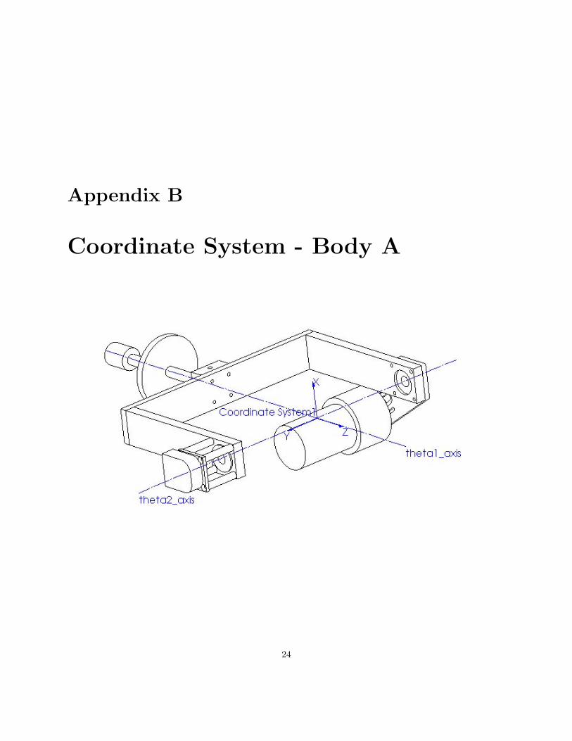
Based on a Solidworks model of our system, the inertia tensors for bodies A and B with respect to thedefined output coordinate systems as shown in Figures B and C were found to be:
Ia =
.0123 .0004 .0004.0004 .0092 .0009.0004 .0009 .0035
Ib =
.0021 0 00 .0005 00 0 .0025
(3.1)
Solidworks also provided the total mass of the bodies. Since the equations of motion were left in symbolicform, values for inertia, mass, and other parameters can be easily changed.
In addition to these equations of motion for bodies for bodies A and B, a model must be developed for theball itself, body C. In Professor Craig’s previous work in the Mechatronics department here at RPI, equationsof motion for the ball based on the platform angles were developed. Based on the small angle assumptionmade, Eqs. (3) and (4) in [3], should hold true for our system. This provides us with equations of motionfor the ball in non-linear form. For now, the non-linear model will be considered, however Professor Craig’s
6
system was linearized to decouple the two modes of motion. See Eq. (5) in [3]. The inertia of the ball wasfound for the equation of inertia for a solid sphere[5].
Ic =25mcr
2b
3.2 Performance Specifications vs. Available Components
Beginning with the physical specifications of the desired system, quickly we see that we require severalsimple parts that are unavailable from the set of components with which we have been provided. In orderto construct the system, several metal parts need to be machined in order to accommodate the 10.4 inchtouch-screen platform. These parts include a new yoke, motor mount plate, and specialized shaft. The yokeand mount plate are much larger than those originally provided, and material has been removed from alarger diameter shaft in order to position the platform at the center of the axis of rotation. The overallweight of the final system will be approximately 1.2 kg. These parts can all be seen in the cad model inFigure D.
High torque, high speed motors will be employed in the system. They are a necessary result of the combina-tion of several factors. The system will be fairly heavy and a large gravity loading will be placed upon eachmotor, especially the base tilt axis which will support the entire system. The plate will tilt over a ±35 rangein one second and thus fairly fasts speeds will be required. These speeds will be necessary to accuratelycontrol the ball’s path with any amount of reasonable speed. It is expected that the motors will be requiredto rotate at speeds of at least 1.35 radians/sec.
High resolution optical encoders will also be employed in the system. In order to control the motion of theball with precision, a decent value for velocity feedback will be required. However, since the touch pad andencoders will only provide position feedback, it will be necessary to integrate the position to find velocity.Making use of optical encoders with a high resolution will help ensure greater accuracy and less noise in thisintegration. The encoders have a resolution of 2048 levels, with quadrature and our A/D converters we canachieve an effective resolution of 4096 levels.
A rubber membrane of 1/16” thickness will be applied to the contact surface of the touch-screen. Thismembrane will serve to provide the friction necessary for the ball to roll rather than slide on the surfacewhile remaining thin enough as to not greatly increase the weight of the ball which will be necessary to readposition information from the touch-screen.
A steel ball bearing of 1.25” diameter and weighing in at approximately 130 grams will serve as the ballin the system. This should provide sufficient weight to cause a response in the touch-screen setup. If afterexperimentation it can be determined that this is excessive, a smaller ball may be substituted.
The touch-screen itself that will be used to detect the position of the ball on the surface is a 10.4” diagonalDynapro 95640 8-wire resistive touch pad. The screen’s total outside dimensions can be seen on the attachedcad drawing. Rather than using the supplied serial encoder, we intend to interface directly with the screen,performing A/D conversions on the read lines in order to determine the position of the ball on the surface.The screen will also have a resolution of 4096 levels, due to the 12-bit A/D converters on the interfacecomputer.
7
It will be necessary to keep noise at a minimum by making clean connections and perhaps shielding wires.The touch-screen operates in an analog fashion over only on a 0-3v range. Any significant noise could leadto inaccurate reading of the position of the ball which would severely limit the accuracy and precision of thefinal system.
3.3 Parameter Identification
Once the system has been constructed, it will be necessary to identify physical parameters of the systemsuch as friction and gravity loading. Friction will occur within the system at various locations such as motor,gear, and joint bearings as well as on the belts and pulleys, however if properly identified this friction canbe canceled. Coulomb friction, which is constant when an object is moving, and viscous friction, which isproportional to velocity, will be lumped together as one friction term and determined experimentally.
A Simulink diagram capable of outputting constant voltages and measuring the encoders will be used torepeatedly estimate joint velocity. A MATLAB script is being written to automate this process so thatmultiple trials may be easily run and averaged to get the best approximation of the friction parameter. Itshould be noted however that this measurement will be limited by the fact that velocity is being estimated.Any variance from the actual friction measurement will have to be considered a disturbance.
3.4 Simulation
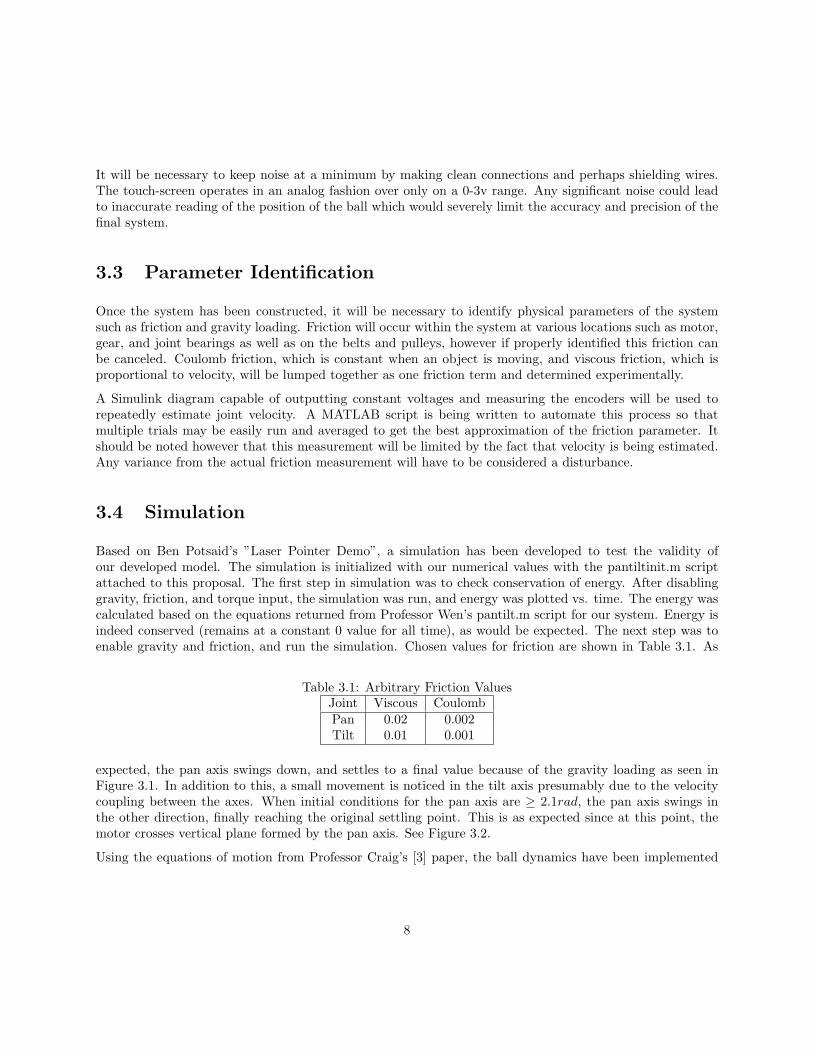
Based on Ben Potsaid’s ”Laser Pointer Demo”, a simulation has been developed to test the validity ofour developed model. The simulation is initialized with our numerical values with the pantiltinit.m scriptattached to this proposal. The first step in simulation was to check conservation of energy. After disablinggravity, friction, and torque input, the simulation was run, and energy was plotted vs. time. The energy wascalculated based on the equations returned from Professor Wen’s pantilt.m script for our system. Energy isindeed conserved (remains at a constant 0 value for all time), as would be expected. The next step was toenable gravity and friction, and run the simulation. Chosen values for friction are shown in Table 3.1. As
Table 3.1: Arbitrary Friction ValuesJoint Viscous CoulombPan 0.02 0.002Tilt 0.01 0.001
expected, the pan axis swings down, and settles to a final value because of the gravity loading as seen inFigure 3.1. In addition to this, a small movement is noticed in the tilt axis presumably due to the velocitycoupling between the axes. When initial conditions for the pan axis are ≥ 2.1rad, the pan axis swings inthe other direction, finally reaching the original settling point. This is as expected since at this point, themotor crosses vertical plane formed by the pan axis. See Figure 3.2.
Using the equations of motion from Professor Craig’s [3] paper, the ball dynamics have been implemented
8
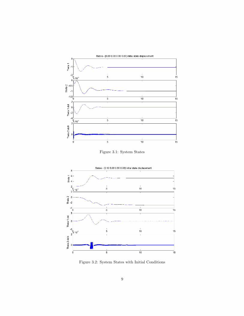
Figure 3.1: System States
Figure 3.2: System States with Initial Conditions
9

into the simulation. From the equations, we can solve for x and y in terms of the state variables:
u =[θ1 θ2 θ1 θ2 θ1 θ2 x y x y
](3.2)
To do this, initial conditions are given to x, y, x, and y. Then, x and y are calculated and integrated tofind x and y. A simulation diagram is given in Figure 3.3. More simulation needs to be done to test thevalidity of this model, however some simple simulations have been run. To test, gravity was removed fromthe base system, but kept on the ball. The plate was given an initial condition in one direction of 0.1rad.As expected, the ball accelerates in one direction, as seen in Figure 3.4.
Figure 3.3: Simulation Diagram for Ball Dynamics
Figure 3.4: Ball States
10
3.5 Controller Design and Tuning
Based on the simulation that we are currently developing, a control system can be developed. As noted inChapter 5, different controllers are planed to be developed depending on our success in each phase. Initially,we aim simply to balance the ball on the plate. This can be achieved with a traditional PID controller throughroot-locus and frequency-response analysis. Upon successful completion of this phase, a more sophisticatedcontroller will be designed to allow us to accurately control the position of the ball on the plate and rejectdisturbances. To do this, we plan on implementing a full state-feedback controller. For our system, the statevector would be of the form:
x :=[
θ1 θ2 θ1 θ2 xb yb xb yb
]T
(3.3)
Since our model is in a non-linear form, the system must be linearized about an operating point [6] (θ, θ) =(θd, 0). Another more advanced technique we may pursue upon completion of the former controller is toimplement a linear-quadratic state-feedback regulator (LQR). To obtain higher accuracy, the system will belinearized around a number of operating points corresponding to different variations of θ and θ. Gains will becalculated off-line for the LQR at each operating point, and stored in a look-up-table. A simple interpolationfunction will determine the gains for intermediate states. This will allow the controller to respond quicklysince all gains are calculated off-line, and state variables should be optimally controlled.
An additional approach may be to implement an observer design. Since velocity cannot be directly measured,finite difference and/or washout filter methods would normally be used to estimate velocity from positionmeasurements. However, these methods often produce unwanted noise. A possible solution to this would beto implement an observer to estimate the velocity:
x(k + 1) = Ax(k) + Bu(k) + L(y(k)− y(k)) (3.4)y(k) + Cx(k)
where L in Eq. 3.4 represents a column vector designed to cause the observer error e(k) := x(k) − x(k) toconverge to zero [2].
3.6 Design Alternatives
Several control design alternatives are currently being contemplated in an attempt to achieve optimumperformance from the system. Initially, PID control will be utilized using a linearized model in order toachieve an initial working system with which to further develop other systems. However, due to the non-linear nature of the system, its inherent unbalanced state, and the complexity of the feedback system, it isexpected that in order to achieve the desired performance specifications and a high degree of accuracy, astate-feedback controller will be required.
Several designs will need to be developed and compared, however. Working with MATLAB Simulink, ascript will be created to run each control design through a specified set of maneuvers: simple plate motions,static ball balancing, and ball path following. After the completion of the runs, graphs of the actual motionsand states of the system can be compared to analyze overshoot, response time, and overall accuracy andperformance.
11

3.7 Subsystem Development
3.7.1 Touch pad
The touch pad is the key piece to achieving our objective of balancing a ball on a plate. The touch padwe will use is a resistive element, returning an analog voltage corresponding to the location of the pressureapplied to it. The pad is an 8-wire panel, but it needs to be pulsed in order to retrieve location information.Each axis needs to be pulsed separately, and the analog voltage read off a single pin. This pin diagram isshow in Table 3.2 [1].
The touch pad as received came with a serial (RS-232) interface controller card capable of controlling thetouch pad and retrieving data points from it. Our concern, however, is the accuracy of the controller, as wellas the difficulty in using it with the MATLAB xPC target software. The controller uses a Texas Instruments10-bit A/D converter, and the concern is that the resolution of 1024x1024 capable with this converter willbe insufficient for our application.
To achieve a higher resolution, a software and hardware interface will be created to connect the touch paddirectly into the A/D hardware of the computer system being employed to develop the control system. The12-bit A/D converters included will increase the possible resolution from the screen to 4096x4096, a 16-foldincrease in resolution. This system will use MATLAB code in the Simulink model to pulse the excite pins ofthe touch pad, and simultaneously retrieve A/D samples from the output pin. The code will do this for eachaxis, back and forth, to create (X,Y) coordinate pairs for use in the control system code. We believe thatusing this level of integration, we can easily best the provided controller’s sampling rate of 80-90 samplesper second.
Table 3.2: Touchpad PinoutAxis Xe+ Xe− Y e+ Y e− Xs+ Xs− Y s+ Y s−
X 5v GND NC READ Ref+ Ref- NC NCY NC READ 5v GND NC NC Ref+ Ref-
3.7.2 Inclinometer
The ball-on-plate system is based on the concept of balance. However, in order to be balanced, the system hasto know what it means to be balanced. This means having both axes exactly parallel to ground, perpendicularto gravity. To accomplish this, inclinometers will be installed on each of the two tilt axes. This will makecertain that during initial start-up and calibration, the system starts in a position that it knows to be zero.
The inclinometers will be attached to the tilt axes, and their output signal interfaced directly to the A/Dconverters of the computer system. These signals will then be read from the MATLAB code for use in thesystem calibration during start-up.
12

Chapter 4
Verification
4.1 Testing Procedure
Though little testing will be necessary for the newly machined parts, it should be noted that they must beaccurately made. It is especially important that the axle be straight and the holes in the yoke be of theproper size and exact placement in the yoke so that the platform will properly spin about the tilt axis. Thiscan be tested by simple measurement and observation.
The test of the motors’ ability to perform their task will be quite simply whether they are able to ro-tate this heavy system at the speeds desired in order to control the ball. This will be testable with aSimulink/MATLAB setup. Various inputs and the resulting position graphs read from the encoder caneasily be used to test the limits of the motor’s ability.
The optical encoder’s performance also can easily be tested with MATLAB. Especially of interest will beresulting velocity graphs that will be a result of integrating the position feedback provided by the encoder.
Testing of the touch-screen subsystem will be necessary to ensure accurate position information will beavailable for feedback in the control algorithm. In addition, the touch-screen sensitivity to the ball weightand the effectiveness of the rubber membrane covering the screen, will require testing to ensure that allcomponents of this subsystem are effective but in no way excessive. To test touch-screen feedback, oncethe subsystem has been implemented the ball will have to be placed on the screen at several locations andthe position read by the subsystem compared to the actual location of the ball. Precise measuring will benecessary here. It may also be desirable to check for precision of position feedback for the ball in motion,however it will be nearly impossible to measure this accurately enough for comparison in the physical world.At minimum however, a plot of the balls path could be observed. The smoother this resulting plot, thebetter.
During the testing of the position feedback, the effect of the ball’s weight on the touch-screen must also benoted. If the ball is not always successful in exciting the touch-screen, it will be necessary to increase the sizeand weight of the ball. However if the ball is performing perfectly, this will be an indication that a smallerball of less weight could be used. This is desirable as there is finite amount of space on the platform and the
13

more space that is available, the greater the range of movement the ball will have on the plate.
One less complex, but still important test of this subsystem remains. The ball must be placed on thesurface when tilted at its steepest angle and observed. If the ball rolls, then the rubber membrane isproviding sufficient friction. However if any slipping at all occurs, it will be necessary to upgrade to a thickermembrane. This however could also affect the necessary weight of the ball and perhaps position feedback,so this simple test of the touch-screen subsystem will be performed first.
4.2 Tolerance Analysis
The physical machine parts require great accuracy. While this should not be overly difficult to implementand test, any deviations from the correct measurements could lead to unrecoverable faults in the performanceof the system. Care will have to be taken in their construction and the final test of their performance willbe the smoothness of rotation of the tilt axis which they implement.
It also is important to the success of the system that the motors and encoders perform well. However, inthe event that they are sub-par some correction other than replacement will need to be implemented if thesystem is still to be a success. There simply are no better motors or encoders available to us. Fortunately,they should be satisfactory As stated earlier, it is necessary for the touch-screen subsystem to be highlyaccurate. If the position feedback for the ball is not accurate, the overall ability to control the system willbe greatly reduced. The system will be tested as described in the prior section and any possible calibrationor noise cancellation will be implemented. The final test will of course be the overall ability of the system.
Barring some unforeseen problem with the machined parts, motors, or encoders, it is likely that the greatestbarrier for perfection in the performance of the system will be the accuracy of the touch-screen subsystem.If this subsystem does not provide an accurate error signal, an ideal control system will never be achieved.
14

Chapter 5
Cost and Schedule
5.1 Cost Analysis
The cost for developing the system can be broken down into the cost for parts, the cost for raw materials,and the cost for labor.
Table 5.1: List of partsItem Qty Cost Total Source
1 1/4” diam. 440C stainless ball 1 $9.17 $9.17 McMaster-CarrDynapro 95640 10.4” 8-wire resistive touch pad 1 $39 $39 Ebay
Pittman motor GM9234S017 (pan) 1 $97.59 $97.59 SuppliedPittman motor GM9234S017 (tilt) 1 $97.59 $97.59 Supplied
Pan gear A 1 $9.97 $9.97 SuppliedPan gear B 1 $22.02 $22.02 SuppliedTilt gear A 1 $7.95 $7.95 SuppliedTile gear B 1 $22.02 $22.02 SuppliedPan belt 1 $3.92 $3.92 SuppliedTilt belt 1 $4.00 $4.00 SuppliedTotal $313.23
Table 5.2: List of raw materialsItem Qty Cost Total Source
1/2” aluminum stock 5 lb $4/lb $20 RPI Machine Shop1 1/4” diam. aluminum round stock 4 lb $4/lb $16 RPI Machine Shop
1/16” latex rubber membrane 1 $9.38 (12”x12”) $9.38 McMaster-CarrTotal $45.38
15

Table 5.3: Labor costsDescription Hours Cost Total
Andrews, Greg (engineer) 300 $35/hr $10,500Colasuonno, Chris (engineer) 300 $35/hr $10,500Herrmann, Aaron (engineer) 300 $35/hr $10,500Caskey, Ryan (machinist) 10 $35/hr $350
Total 910 $31,850
5.2 Phases
The development of the ball-on-plate system can be generalized into several phases to overall project com-pletion. Basic system completion entails the ability to balance a ball in a static position on the sensor plate.The target advanced system builds on the basic system and allows for simple as well as complex trajectoryfollowing of the ball.
1. Initial development
System modeling Using physical parameters for the individual system pieces and a CAD model,the inertia and mass matrices can be generated. These can then be used to generate the corio-lis/centrifugal matrices, which can be used to generate the dynamics of the system.
Additional parts construction Additional parts are needed for the central plate yoke, which needto be machined in the machine shop.
2. Identification
Parameter identification Using a MATLAB script, the physical system can be run through severaltests to determine the parameters describing the full model, including friction terms.
Validation Once these parameters are defined, the physical system response can be compared to theprojected response, and the std.dev of this response can be used to further define the systemparameters.
3. Controller
Control design Once the system is defined, the controller can be developed. Several different designsare planned, including a PID controller, a State-feedback—observer controller, and an Optimalcontroller.
Sensors The sensor development and integration will need to be finalized by this point, including thetesting of the inclinometers, touch pad, and encoders.
4. Integration
Integration Move the sensors from testing into the physical system. Also, integrate the control designinto the Simulink system for usage with MATLAB xPC target.
Testing With the control system now operating, test to make sure the system can be calibrated, andmaintains position to within a small percentage of the desired position. Also, check for responsetime and disturbance rejection in the joint angles.
16

5. Basic System
Static ball balancing Move system from basic controller to balancing system. This includes feedbackfrom the touchpad in order to monitor ball position and dynamics in an attempt to maintain staticball position.
Disturbance rejection With the ball static, attempt to nudge the ball from its current position, tomake certain that the control system can compensate for unknown random forces.
6. Advanced System
Line trajectory tracking (slow) With static ball balancing working, work on moving the ball alonga line trajectory (e.g. y = x), such that it can traverse from one corner of the work surface toanother.
Line trajectory tracking (fast) Increase the speed of the traverse until the system can move theball rapidly, but under control.
Complex trajectory tracking Now that a line path can be rapidly tracked, attempt to make figure-eight, circular or more complex paths for the ball to follow.
MATLAB GUI interface to tracking (optional) Develop a MATLAB gui to allow for simplifiedcontrol of different tracking examples. This system could possibly include a grid on which a usercould pick points, and have the ball trace out a simple path.
5.3 Schedule
A proposed overall development schedule is shown in Table 5.4. While preliminary, the schedule is realisticand aims for advanced system completion before the final demonstration day. The schedule also includesinformation on task breakdown between members; however, the foreseen complexity of the project and ofeach task suggests that each task might likely be completed by the group at large, with the designated teammember merely acting as lead.
17

Table 5.4: ScheduleWeek Task MemberWeek 4 Model development Greg
Research sensing hardware AaronFind machinist to make metal parts Chris
Week 5 Model development GregTest sensing hardware Aaron
Work on machining parts ChrisWork on project proposal Team
Week 6 Model development GregResearch sensing interface options Aaron
Friction ID script ChrisWork on project proposal Team
Week 7 Friction ID TeamWeek 8 Model validation Chris
Develop sensor interface AaronPreliminary control design Greg
Week 9 Control design Greg, ChrisFinish sensor interface Aaron
Week 10 Integration of sensors AaronControl system testing Greg
Sensor testing ChrisWeek 11 Static ball balancing TeamWeek 12 Complex path following TeamWeek 13 Work on final report Team
Final demonstration TeamWeek 14 Work in final report Team
Final presentation TeamWeek 15 Final report Team
18

Bibliography
[1] 3M Touch Systems. SC4 Touch Screen Controller: User’s Guide, 2nd edition, 2003.
[2] Dr. Murat Arcak. Discrete time systems - lecture notes. 2003.
[3] S. Awtar, C. Bernard, N. Boklund, A. Master, D. Ueda, and K. Craig. Mechatronic design of a ball-on-plate balancing system. Technical report, Rensselaer Polytechnic Institute, 2002.
[4] Graham Goodwin, Stefan Graebe, and Mario Salgado. Control system design - ball-on-plate tutorial.Available WWW: http://csd.newcastle.edu.au/control/simulations/ball sim.html, 2001.
[5] Eric W. Weisstein. Moment of inertia - sphere. Available WWW: http://scienceworld.wolfram.com/physics/MomentofInertiaSphere.html.
[6] Dr. John Wen. Control system design - lecture notes. 2004.
19

Chapter 6
Statement of Contribution
For the project proposal document:
Greg completed the following sections:
• Model development
• Controller design and tuning
• Simulation
• CAD model
Chris completed the following sections:
• Performance specs vs. available components
• Parameter identification
• Testing procedures
• Tolerance analysis
Aaron completed the following sections:
• Abstract
• Introduction
• Objectives
• Design alternatives
• Subsystem development
• Cost analysis
• Phases
• Schedule
20

Greg Andrews Chris Colasuonno Aaron Herrmann
21

Appendix A
Touch pad data sheet
22

23
Appendix B
Coordinate System - Body A
24

Appendix C
Coordinate System - Body B
25

Appendix D
CAD Model
26