GROUNDWATERQUALI1Y .. ASSESSMENT PLAN .... INTRODUCTION GROUNDWATER QUALITY ASSESSi\IIENT PLAl'i...
67
_ .. .. . - .. ·-· .. - GROUNDWATERQUALI1Y .. ASSESSMENT PLAN . DICKSON DICKSON COUNTY, TENNEsSEE NOVEMBER, 1994 Prepared By GRIGGS & 1\tlALONEY · JNCORPO"HATE!:! l::::rt •J.rcnmcn ;JI 745 South Church St, Suite 205 PO Box 2968 (37133-2968) Murfreesboro, Tennessee 37130 (615) 895-8221• (615) 895-0632 FAX File Number 143-05 . :..:.:.- - ·:,:. -_ .. .. ::.····:··- · :·. :-.:-:-;-_-- :· -- .. ... . .. .. --· .. - - .:·· - "":"'- ...... .; .. -·- -
Transcript of GROUNDWATERQUALI1Y .. ASSESSMENT PLAN .... INTRODUCTION GROUNDWATER QUALITY ASSESSi\IIENT PLAl'i...
~ · _ ..
.. . - .. ·-· .. -
-~"' GROUNDWATERQUALI1Y .. ~~ ASSESSMENT PLAN .
DICKSON COUNTY~ DICKSON COUNTY, TENNEsSEE
NOVEMBER, 1994
Prepared By
GRIGGS & 1\tlALONEY · JNCORPO"HATE!:!
Engtn~cnng.:!. l::::rt•J.rcnmcn;JI Ccn::ulhn~
745 South Church St, Suite 205 PO Box 2968 (37133-2968)
Murfreesboro, Tennessee 37130 (615) 895-8221• (615) 895-0632 FAX
File Number 143-05
. :..:.:.-- ·:,:.-_ .. :..:.~ .. ::.····:··- · :·.:-.:-:-;-_-- :·-- .. .... .. .. --· .. - - ~-. ~:: .:·· - "":"'- ...... .; .. -·- -
,.
•
TABLE OF CONTENTS P:1ge LIST OF FIGURES ...................................... ···•··•••··· ..................................................................... i LIST OF TABLES ................................................................. · ....................................................... ii Lis'r OF APPEND[CES ....................... •.• ........................................... - ........................................ iii
1. Jl.riRODUCTION ............................ ~ ............................................ - ......................................... 1 2. SCOPE-oF-WORE.. .......................................................... _ ........... _ ....................................... 1 3. BACKGROUND !NFOR...'v!A.TION ............. .' .................................. ~ ............................................... 1 3 .I. Site Location and History ................................................ - ........................... ~············· 1 3.2. GeOlogy .............................................................. ; ........... - ...................... ~····· ............... 5 3 .3. Hydrology .. ~ .................................................................... _ ......................................... 6 3 .3 .I Surface Water ................................................. ; ........ _ ......................................... 6 3 .3 .2 ·Groundwa!er ........................................... ~··········~······-····· .................................... 1 3 .3 .3 Water Usage ........................................................ ~ .. ·-····· ................ : ......... : ........ 9 4. INVEsTIGATION PROCEDURES ............................ ~ ...................... _ .................. : ..................... 9 4.1 Monitoring Well Locations and Depths ............................. _ ...................... ; ................. 9 4.2 Well Drilling Methods ........................................................ - ........................ _ ........... 13 4.3. Decont.a.mination Procedures .................. ·, ......................... - ..................................... 13 .4.4. Well ConstrUction Methods ............................................ _ ...................................... 14 4.4.1 Single Cased WeU lDstallation Procedures .. :._ ......... _ ......... ~ ........... ~ ................ 14 4.4.2 Double Cased Well Installation Procedures .............. - ..... : ................................. 16 4.5 Well Development Methods .............................................. _ ...................................... 18 4.6 Contaminants-Of-Concern ............................................... ~-.... ; .................. -: ............. 18 4. 7. Groundwater Sampling ....................................... , ...................................................... 20 4. 8 Groundwater An.alysis. ...................................................... :_ ...................................... 21 4.9 Sa.ID.ple Labeling And Handling ......................................... ~ ...................................... 21 4.9.1 Sample Packaging And Shipping .... ' ...................... : ... - ...................................... 22 . 4.9.2. Sample Chain-Of-Custody ..... : .................................. - ..................................... 22 4.10 Sampling Quality Assurance I Quality Control... .............. .-..................................... 23 4.10.1 Trip Blanks ........................................... ; .......................................................... i4 4.10.2 Equipment Blanb ............................................................................................ 24 4.10..3 Duplicate Samples/Split Samples ............ ~ ......................................................... 25 4.! c . .;; F~e!d. E·t!r~G ............................... ~ ................................................................................................ 25 4.11 Survey For Streams, Springs, and Wells ......................... : .......................................... 25 4.12 Additional Phases OfThe Investigation ................. ~ .................................................. 25
. 5. 0 REPoRT OF FINDJ:NGS ................................ ·. ······· ...................... .:.... .... ; ................................. 26
6. 0 SCHEDULE OF ML&!ENTATION ............................................. - ...................................... 26
LIST OF FIGURES
FIGURE 1. SITE LOCATION/TOPOGRAPHIC MAP .................................. : •...•.......••....•...••••••••••.•• 3 . .
FlGiJRE 2. Sl'IE LOCATION MAP SHOWING ExisTING MONITORING WEil.S AND SPRING .....•.... 4
· FtGUR.E 3- REGIONAL WATER. LEVEL CONTOURM<\P ....•• : .•.•...•......•.•••...•...•.•.•..................••••..•. 8
FIGURE 4 - w JtJER. WEI.I. LocATION IvW ..................................................... : ........... - ........ 10
FiGURE S SITE LOCATION MAP SHOWING PROPOSED MONITORING WEU. LocATIONS .......... 12
FIGURJ;: 6 S1NGLE CASED WELL DIAGRAM .............................................. ~ ............................. 15
FIGURE 7 DoUBLE CASED WEIL DIAGRAM .......................................................................... 17
FIGURE 8 MONII'ORlNG WEll. DEVELOPMENT FORM .............................................................. 19 .
LIST OFT ABLES
'TABLE l'WAm.. WELL USEJNFORMAnON ........................ : ............ _ .................................. ~ ... 1 I
TABI.E2 GROUNDWA'IER. SAlv!PLEHANDLING AND ANALYSIS SUMMARY ... - ........................... 21 ·
TABLE 3 SOIL SAl'APLES QA/QC R.EQ~ ..................................................................... 24
LIST OF APPENDICES
APPENDIX A. APPENDIX II. • GROt.JNDWA.TE:RMONITORING LIST
APPENDIX B. SAMPLING A'ID ANALYSIS QUALITY AsSURANCE/QUALITY CON'IROL PLAN

1. INTRODUCTION
GROUNDWATER QUALITY ASSESSi\IIENT PLAl'i
DICKSON COUNTY LANDFU.L DICKSON COUNTY, TENNESSEE
Griggs & Maloney, Inc. has b~n retained by Dickson County to prepare a site investigation plan to assess the groundwater quality at the Dickson County Landfill, Dickson, Tennessee. The Tennessee Division of Solid Waste Management (DSWM) directed DickSon County to deveiop a groundwater quality assessment plan afb::rsampling"fr0ri1 a:- spring: neat:tlie.tandfill:indicated':S'Oiid waste- constituents from"'='the..landfi1Lma.y: have:. migrated;. imo "-the:. groundwater. · This document . descnces the objectives· of the investigation, provides background information concerning the land.fill. and gives a detailed description of the work plan for the groundwater quality assessment.
2. SCOPE-OF-WORK
This Groundwater Quality Assessment Plan is designed to serve as the primary guidance document .for the groundwater quality assessment at the landfill The overall objectiveS of the assessment are, as required in the Solid Waste Regulations: :if"etermrmm~o£.wtt~~li.¢.waste_z constituents",ba:ve .. enterecflfie:-ground~and~characteriza:tiotr"of:th&.'concentrattons-ailcr--'ra.fe and' e::aent:o(rgigrar;~~ofwast~C2_~e,g~i£1 .. the;gr~~t
Multiple phases of investigation will be needed to complete the investigation. Because the need for an assessment monitoring program was initially indicated by sampling results from an off-site spring,. the iiiitiiU.~obJective ~will be ·to· determme7whether the~waste·constirueott-detec:ted in.~~e spring came ·.from · the:·landfill. ., This will be accomplished by the installation of additional monitoring wells between the spring and the landfilL Additional hydrogeologic information will also be gathered by surveys to identity all springs. streams, and domestic and commercial water wells in the area. Other investigative work will be performed as necessary to meet the stated or~~~t~s cf:~,e :~,-~~~~~g!~~r-
... .., GR!aas & MA.l.oNr:Y, INc. • En~rtng and Environmental Consulting • (61.5) S 95-8221 Page 1
GROtJti!DWATER QU,\l.lTY AssESSMENT PUN • DICKSOI'f Co!JNl"Y l.:.\,('(l)FTLL NOVF.I\tDER. 1994
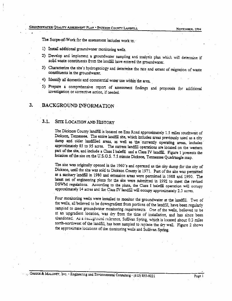
The Scope-of-Work for the assessment includes work to:·
1) Install additional groundwater monitoring wells. 2) Develop and implement a groundwater sampling and analysis plan which will determine if
solid waste constituents from the landfill have entered the groundwater. 3) Characterize the site's hydrogeology and deterinine the rate and extent of migration of waste constituents in the groundwater. · · 4) Identify an·domestic and comiilercial water use within the area. . 5) Prepare a comprehensive report of assessment findings and proposals for additional
investigation or corrective action, if needed.
3. BACKGROUND INFORMATION
. · 3.1. SITE LOCATION AND HISTORY
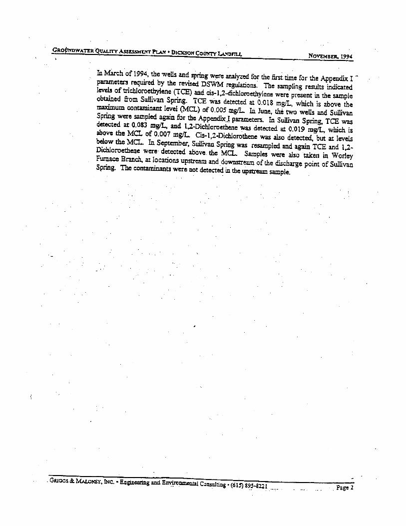
The Dickson County landfill is located on Eno Road approximately 1.5 miles southweSt of Dickson, Teooessee. · The entire landfill site, which includes areas previously used as a city dump and older landfilled areas, as well as the . currently operating areas. includes . approximately 85 to 95 acres. The curreiu: landfill operations are located on the western part of the site, and include a Class I balefill and a Class IV landfill. Figure 1 presents the location of the site on the U.S. G. S. 7 .S. minute Dickson, Tennessee Quadr.mgle map.
The site was origi!lally opened in the 1960's and operated as the city dump :for the city of Dickson, until the site was sold to Dickson County in 1971. Part of the site was permitted as a sanita!y landfill in 1980 and extension areas were permitted in 1988 and 1990. The latest set of engineering plans for the site were submitted in 1992 to meet the revised DS'WM regulations. According to the plans, the Class I baleDll operation will occupy approximately 14 acres and the C_lass IV landfill will occupy approx:imateiy 2.3 acres.
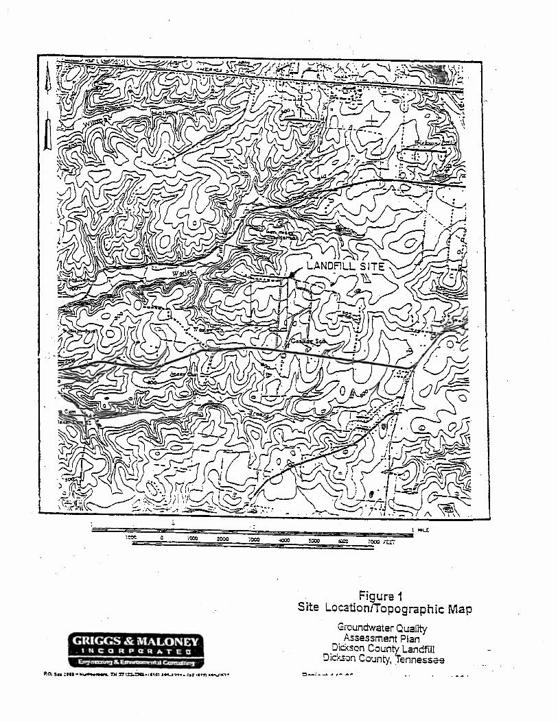
Four monitoring wells were installed to monitor the groundwater at the landfill. Two of the wells, all believed to be downgradient from portions of the landfil~ have been regularly sampled to meet groundwater monitoring require:n::.ts. One of the wells, believed to be at an upgradient location, was dry from the time of installation, and has since been abandoned. As a oa~:qrounci ri:;£a:-enc:, Sulli\ran Spring, which is located about 0.3 miles north-northwest of the landfill, has be-..n sampled to replace the dry well. Figure 2 shows the approximate locations of the monitoring wells and Sullivan Spring .
. . -~. GRlOOS & MAL.oNU, INc. • Engin=ring and Environmental Consulting • (6LS) &95-822.1 P:~ge 1
NOvtMBP. 1994
In March of 1994, the wells and spring were analyzed for the firn.time for the Appendix Iparameters required by the revised DSWM regulations~ The sampling results indicated levels of trichloroethylene (ICE) and cis-1,2-<fich.loroethylene were present in the sample obtained from Sullivan Spring. TCE Wa.s deteaed at 0.018 mg/L, which is above the maximum conta.minant level (MCL) of 0.005 mgtL. Io.Iune, the two weUs and Sullivan Spring were sampled again for the Appendbc.I parameters.. In Sullivan Spring, TCE was detected at 0.08:3 mgll., and 1.2-Dichloroethene was detected at 0.019 mgll. which is above the MCL of 0.007 mgtL. Cis-1,2..0ichlorothene was also detected, but at levels below the MCL. In September, Su.lli:van Spring was resampled and again TCE and 1,2-Dic:hloroethene were· detected above. the MCL. Samples were also taken in Worley Furnace Branch. at locations upstream and downstream of the discharge point of Sullivan Spring. The contaminants were not detect~ in the upstream sample.
- GiUOOS & M.Au:lHEY, INC. • Engin=Ulg anciE~nment!l Consulting • (615) 89~-3221 .•..•. . Page 2
GRIGGS & MALONEY IMCORPctRATED
. Figure 1 . Site LocationiTopographlc Map
Groundwater Quality Assessment Plan
Dic-<son County Landfill Dickson County, Tennessee
o-:- ..... ,. ~- ""~
GRIGGS & MALONEY I N ~ a R P a R A T C D
•n ·-~• •a..- ~ .,'T ..... - ....... , ·- -·- ..... ••••• -· ---
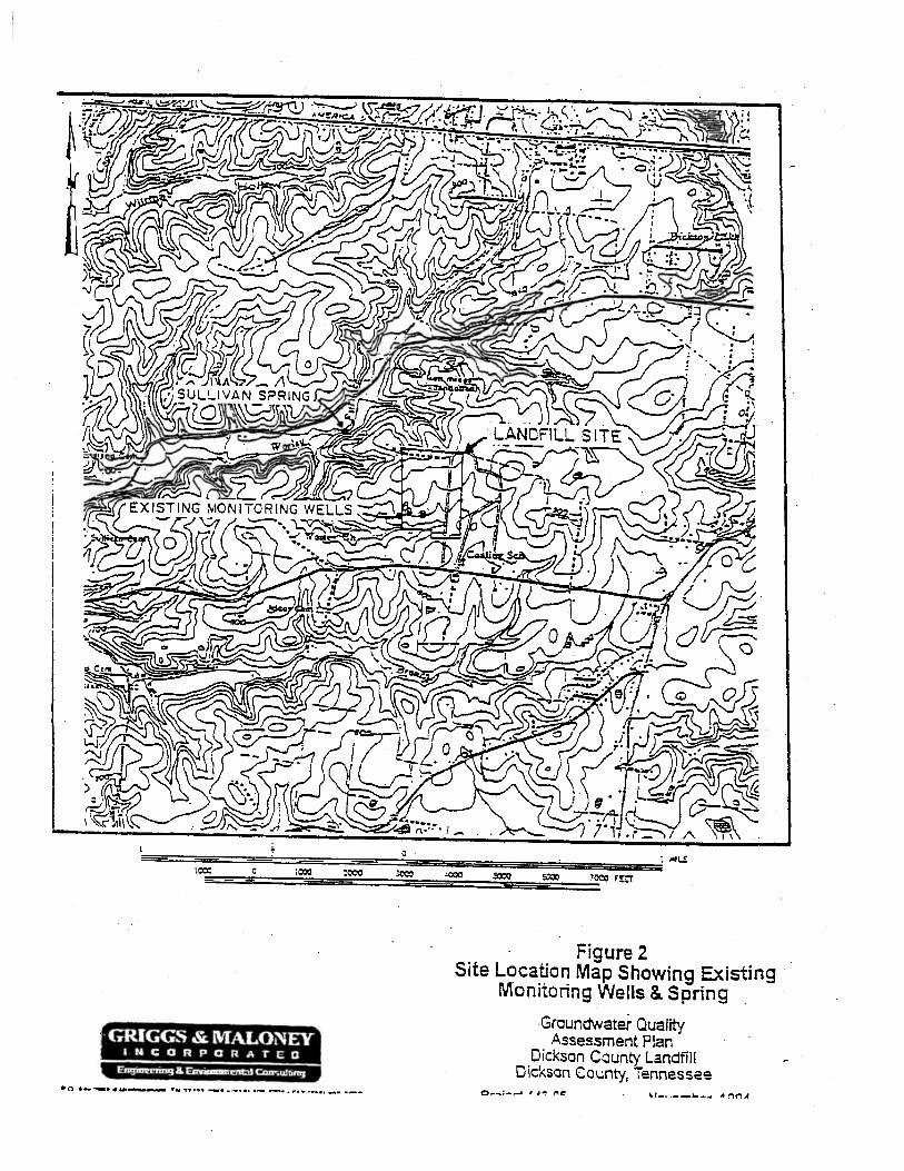
Figure 2 Site Location Map Showing Existing
Monitoring Wells & Spring . -Ground'Nater Quality
Assessment Plan Dickson County Landfill
Dickson County, Tennessee

GROttmJWATER QUALIT'\" ASSESSMENT Purr • DICKSON CouN-n- LANDFILL NOVEMlJER. 1994
Sullivan Spring is. used as a drinking water source by two families. At the time of theSeptember sampling, the residences were notified by ?vfr. Jirri Lunn, of Dickson County, that they should not use the water for drinki.ng until further notice. The Division of Water Pollution Control was al?O notified. of the findings at this time. In September, surface water sampllitg was conducted at va.riow points on West Piney Cr~k. Sampling did not reveal detectable levels of any of the parameters. Residential wells on Furnace Hollow Road were also sampled during September. The laboratory results did llOt detect any of the parameters in question. (Gardner, 1994)
3.2. GEOLOGY
The Dickson County Landfill is located on the rolling plateau of the western Highland Rim, a section of the Interior Low Plateaus Physiographic province. The region is characterized by rolling terrain which has been cut by numerous streams. A mantle of unconsolidated regolith, of varying thickness, overlies Mississippian carbonate bedrock. (Bradley, 1984)
The ~andfill site is located on a rolling upland area which drainS primarily tow~d Worley. Furnace Branch and it's tnbutaries to the southwest, west, and northwest. Slopes ate gentle to moderate Within the .landfill property boundaries, but are steep along the upland slopes. Relief over the landfill site is approximately 60 feet, with the highest elevatioos ~ong the northern end of the landffil and the lowest elevations near the southwestern corner. Over 120 f~t of relief exists betw~ the highest areas ofthe landfill and Worley Furnace Branch.
The uppermost geologic formations in the area of the landfill are, in descending order: the St. Louis Limestone, the Warsaw Limestone, and the Fort Payne Forma.rion, all of which are Mississippian in age. The regional dip of the formations is to the northwest. (Bradley, 1984)
Tne StLouis Limestone caps the uplands over most of the area. At the landfilL for the most part. the unit has weathered to clay regolith. Borings at the landfill have identified the regolith as red, reddish-brown or orange, moderate to highly plastic, silty clay soils with varying amounts of chert fragments· a;.:.;. :::..:~::::. a..•d ::::~u.ies of chert. (ATEC, Gecte:::nic! and Hydrogeologic Investigation, 1992) The borings have revealed that the unconsolidated soils are thick beneath the landfill site. The previous geotechnical borings and wells were d.;~;~ 'c .i~:ti:.s r~.iiki.r.>< from 25 to 39 feet below the surface. Some of • - :;:o the auge: borings were believed to have refused r.-iense chert beds and the A TEC report estimated limestone bedrock to be approx:imatei&o 90 feet below the ground surface.
7 I
GRloos& MALoNEY, INc.· Engineering and Environmt:JJ.tal Consulting· (615) 395--8221 Page 5
:GRoUNllWA TU. QuA.UTY AssEssMENT PUN • DtClOOH CoUNT"i I..Mrom.z.· NOV'F..o.'\fBER. 1994
Bradley, ··1984, estimated the regolith in the uplands of the Dickson area to generallyrange from 50 to more than 150 feet thick.. Comparison of depths to bedrock for reSidential wells and. test wells in the area near the landfill found the a~ regolith thickness to be highly variable within short distances, which indicates that the bedrock sUrface is likely pinnacled. One test well drilled at the southeastern comer of the landfill was drilled to 331 feet before encountering_bedrock. Where not weathered to regolith, the Sl Louis Limestone is typically a. yellowish.,.brown, fine-grained, cherty limestone. (Bradley, 1984)
The Wmaw Limestone underlies the StLouis Limestone. Bradley, 1984, estimated the top of the Warsaw limestone to be near the 740 foot contour in the area of the landfill. This would place the top of the Warsaw at about 60 to 130 feet beneath the landfill site. The Warsaw Limestone is typic:ally a thick-bedded, light-Colored. medium- to coarsegrained, fossil fragmental limestone. Locally the upper part of the Warsaw may be weathered to. clay regolith in some locations ii1 the vicinity of the landfill. The unit is approximately 100 feet thick in the area. (Bradley, 1984)
The Fort Payne Foimation is typically a. calcareouS. dolomitic, very cherty siltstone. It is estimated to have a maximum thickness of approximately 250 feet in the Dickson Area.. (Bradley, 1984)
3.3. HYDROLOGY
3.3.1 SURFACE WATER
The landfill site drains primarily to· the· southwest, west, and northwest toward Worley Furnace Branch and it's tributaries. Worley Furna.c= Branch is located approximately 0.3 miles north-northwest of the landfill. The headwaters of a tributary of the stream begin at the southern end of the active landfill area. Portions of the southeastern part of the old city dump /landfill area drain to the south toward Baker Branch. Both Worley Furnace Branch and Baker Branch flow into West Piney River, which is located. approxim,ately 1.5 · miles west of the landfill. All ofthe streams are within the Tennessee River Basin:
Numerous s~rings are located in the Dickson area. The spring believed to be the closest to the landfill is Sullivan Spring, which discharges into Worley Furnace Branch about 0.3 r:rules north-northwest of the landfill. The altitude of the spring is near the 720 foot elevation. The spring appears to issue from the limestone bedrock which outcrops along the valley wall ofWo.rley Furnace Branch.
__ GRlOGS &: MALoNEY, lNc. • Engineering and. Environmental Consulting • (615) 895-3221 Page 6

GRQUNOWAT!:R QUAU"TY A.sSESSM£llo"T Pu.'l • Dtc:ASON COUNTY LAi'4DFlLL NOVO::'\IUER. 1994
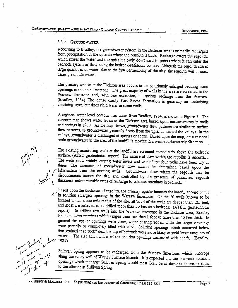
3.3.2 GROUNDWA.n:R
According to Bradley, the groundwater S)istem in tbe Dickson area is primarily recharged from precipitation in the uplands where the regolith is thick. Recharge enters the regolith, which stores the water and transmits it slowly downward to points where it can enter the bedrock system or flow along the bedrock-residuum contact. Although the regolith stores large quantities of water, due to the law permeability of the clay, the regoijth will in mast cases yield little water. ·
The primary aquifer in the Dickson area occurs in the salutionaly enlarged bedding plane operungs in soluable limestone. The great majority of wells in the atea are screened in the Warsaw limestone and., with one exception, all springs recharge from the Warsaw. (Bradley, 1984) The dense cherty Fort Payne Formation is generally an underlying confining layer, but does yield water in· same wells.
A reSional water level contour map taken from Bradley, 1984, is shown in Figure 3. The contour map s~ows water levels in the Dickson area based upon measurements in wells and springs in 1960. As the map shows, groundwater flow patterns CU"e similar to surface flow patterns, as groundwater generally flaws from the uplands toward the valleys. In the valleys, groundwater is discharged at springs or seeps. Based upon the map, on a regional scale groundwater in the area of the landfill is moving in a west-southwesterly direction.
The existing monitoring wells at the landfill are screened immediately above the bedrock SUiface. (ATEC geotechnical report) The nature of flow within the regolith is uncertain.
'
·The wells show Widely varying water levels and two of the four wells have been dry· at times. The ·direction of groundwater flow cannot be determined based upon the
o f infonnation from the existing wells. Groundwater flow within the regolith may be 1. · · · ~continuous acros.s the site, and controUed b_y the p~ese~ce of pinnacles, regolith ~~ thickness and/or vanable rates of recharge to solution opemngs m bedrock. ·.
Based upon the thickness of regolith., the primary aquifer beneath t..1e landfill should occur 1/ in solution enlarged openings in the Warsaw limestone. Of the 20 wells known to be located within a one-rnile radius of the site, all but 4 of the wells are deeper than 125 feoet, and most are believed to be drilled more than 50 f~ into bedrock. (ATEC, geotechnical report) In drilling test wells into the Warsaw limestone in the Dickson area, Bradley f-::·~-:--"- •ch.:.t.~'l r:~~.,!'!~ ·:vl-<~1..: ~"!1ged from less than l foot to more than 40 feet thick. In general th.e smaller ope=ir.gs were c:ean, water be~...:.:.g zones, while the larger openings were partially or completely filled with clay. Sclt.lllcn openings which occurred below fine-grained "cap rock" near the top ofbedrock were more likely to yield large amounts of
1 water. . The size and number of the soiu.tion ope~g3 de~eased with depth. (Bradley, "'' VJ'"'jl, 1984) . ,..-'~ ~ # "" A I"' 1"" J f"
· ' ~<' .. 1 ,..-"'
8 Sullivan Spring appears to be recharged from the_ Warsaw limestone, which outcr~ps "f-"i.-{. f ,""~ ~ along the valley wall of Worley Furnace Branch. It JS expected that the bedrock solunon ~· ~ 1 ~· ;J ( t "'...,r r openings which recharge Sullivan S pri.ng would most likely be at altitudes above. or equal :f .. ~,•({ ~~"" to the altitude at Sullivan Spring. ·
~:"'
.. ·- .Gruaos & MAL.o~n. INc. • Enginc:ring and Environmental Con.su1ting • (6l5) 89.5-8221 Page i

aau ltDIIl u.s. \: ..... -.ec..tl S..W••r. 1:.%0>0110 &U&IIrl ... lfl.: l .... nat tU.lJ. C::Wrtan•l 1 '~tl. Qlc~aUftt 1 ~5.11. 1114' v ..... .,, t~s.IJ
EX?t..:ANA TION
•ooa I (r
I GOO
- dCC - - POT~NTICMe-n:IIC CONTOUR-
a· I !
I
0
S:O.cws al!i tu~a ol ·:r.t1er table. Marc:."! t96U.. Oas:teC wr-f!~.~ z::-:r::::·::--.c.:a!y :.::.:.:;z..:.. ··; .;r.;.;w- .. ~: .=:;ci.: , ..:....; : e: er. Nauanal Gaodetic VenicaJ Oatum at t929
• 'N~!!:; ·v:~~ ••ra:l!~ lava!s ~l~T-1"9C Marcl\, 1560
SClririg3
Oircctian al ground-water IIOVt
NOTE: Map raken from Bradley.
•oao ·aaao '! !": H'Qr04eg II'Uid(Uecf f~OI'II WatGftef. llf•Qll& ........ ~-_,. ,, .... ) I I
1ooo zoao MI!TII:!t$
Figure 3 Regional Water Level Contour Map
Groundwater Quality Assessment Plan
Diooon County Landfill Dickson County, Tennessee
NOVE."vflltR. 1994
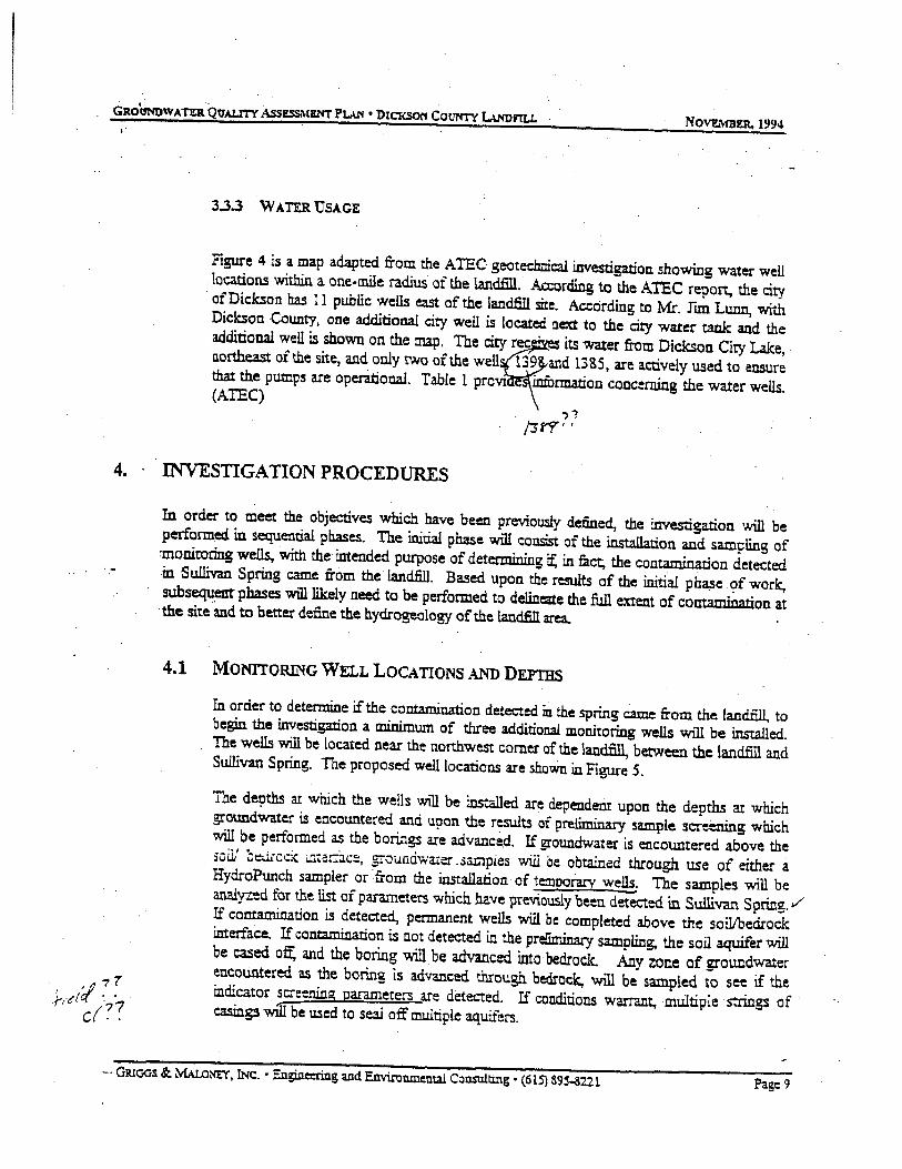
3.3.3 WATER USAGE
Figure 4 is a map adapted from the ATEC geoteclmical investigation showing water well !cations within a one-mile radiuS of the landfill. Ao:crding to the ATEC report, the city ·of Dickson has 11 public weUs east of the landfill site. According to Mr. run Lunn, with Dickson County, one additional city. well is located next to the city water tank and the additional well is shown on the map. The ci~tyec · its water from Dickson City Lake, o.orthea.st of the site, and only two ofthe well 139 and.l385, are actively used to ensure that the pumps are operational. Table 1 provt infucmation concerning the water wells. (ATEC) ?1
(3rT'.
4. · . INVESTIGATION PROCEDURES
In order to meet the objectives which have . been previously defined, the investigation will be performed in sequential phases. The initial phase will consist of the installation and sampling of :monitoring wells, with the· intended purpose of determining it: in fuct, the contamination detected in Sullivan Spring came from the landfill. Based upon the results of the initial phase . <?f work, subsequent phases will likely need to be performed to delineate the full extent of contamination at ·the site -and to better define the hydrogeology of the landfill area.
4.1 MONITORING WELL LOCATIONS AND DEYI'BS
In order to determine if the contamination detected m the spring came from the land.filL to begin the investigation a minimum of three additional monitoring wells will be installed. The wells will be located near the northwest corner of the landfill, between the landfill and Sullivan Spring. The proposed well locations are shoWn. in Figure 5.
The d~ths at which the wells will be installed are dependent upon the depths a:t which groundwater is encountered and upon the results of preliminary sample screening which will be performed as the borings are advanced. If groundwater is encountered above the sc,i1' bt:.:iicc:{ in.ter:ac~. grounci.warer .3ampies will oe obtained through use of either a HydroPunch sampler or ·from the installation of temoor'ary wells. The samples will be analyzed for the list of plU11Illeters which have previously been detecterl in Sullivan Spring./ If contamination is detected, permanent wells will be completed above the soil/bedrock interface. If contjUTljnarion is c.ot detected in the pre!iminary sampling, the soil aquifer will be cased oft: and the boring 'Will be advanced into· bedrock. A1J.y zone of groundwater encoUntered as the boring is advanced through bedrock, will be sampled to see if the indicator screening parameters are detected. If conditions warrant, multiple strings of · casing3 wiii be used to se3.1 off multiple aquifers.
-· GR.toos & MALoNEY, INc. • Engineering and Environmental Consulting • (615} a9j-3221 Page 9

I
ls· =c~~====~~~~~~=a~===========s-=aa=-~~"~! . 0
LEGEND
e - Well loc:ltion and number adapted from ATE:C Report. .
• - Addition Well location supplied by Mr. Jirri Lunn of DicKson County.
Figure 4 Water Well Location Map
Groundwater Quality Assessment Plan
Dickson County Landfill Dickson County, Tennessee
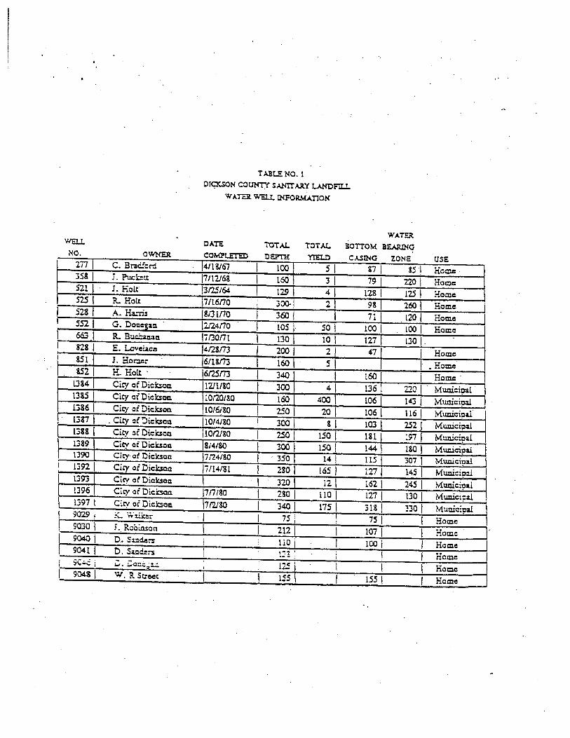
TABLE NO.1 O!CXSON COCJNTY SAN!!" AAY LANDFII..I.
W A!Ei. WEU. INFORMATION
WAT.EJt OATS TOTAL TOTAL BOTTOM BE.AlUNCi
NO. COMPt.ET'ED DEPTH YI'EI..D CASINO ZONE USE 2TI I C. Braciford 4113167 I 100 s I 87 &51 Hoc:e · 358 I I. Pucl.:::tt 17112168 I t60 I 31 79 no I Home 521 I · J. Holt 1312.5/64 I 12.9 41 128 I 125 I Home 5251 R. Holt 7/t6no I 300. 2 98 260 I Home 528 I A.Ha..rru IB13Ino I 360 71 120 I Home 5521 G. Dot:tC1Z!:I. 2124no I LOS I so I reo I too I Home 663.1 R. Bucbanan l7130nt I 130 10 127 t3o 1. 828 I E. Lovc~c.e l412sm I 200 I 2 471 I Home 85lj J. Horner 61um I 160 s I • Home 852 I H. Holt · 617.Sm I 340 I 160 I Heme·
IJs4 i Cicy ofDicksoa. I t2Jt1so I 300 41 136 220 I Mumeipal. 1385 \ Clcy of Dicksoa. 10120/80 I 160 400 I 106 143 I Muniei]:l:U. t386 I City of Dicksoa. 10/6/80 I 25o I 20 I to6 I t16 I Munieip&l 13!7 I . City of Diclaoa. 10!4/80 I 300 I s I to3 I 252 Municipal 1388 I City or Diclaoa ll0!2l80 I 250 150 I 181 197 Munici~al 1389 I City ofDiclr:.soo 8/4/80 I 300 I rsa I 144 I 1so I Muniei?a.i 1390 l Cicy· of Diclcsoa l7n4tso I ·· 350 1 t4 I 115 307 Munici?al 1392 I Cicy of Dicksoll 17114/81 l 2so I 165 I 127 145 Mumci;n.i 13931 Cicy ofDickson I l 320 I 121 1621 24S Muniei-oal 1396 I Cicy of Dickson l7n180 I zso I 1101 121 I 1301 Municipal 1397 I Cicy of Dickson \7f2180 I 340 I 11s I 318 I 3:;o I Municipal I 9029 I ~ ·,:,.·l.ik:::- I I 75 i ! 1s I I Home 9o3o I J. Rcoinson I I 2121 I 101 I I Home
L 9040 I D .. Sz:.d.::-s I I 1l0 i I 100 i I Home I 9041 I D. Sa!!rie:-s I ; ,- ... I
l I I Home .. ·-- :
.sc~: ~ . .C-cc.i:;!..:. ' t25 L I I I Hocc i
I
I 904s I W. R Street I I 1ss I I iSS I I Home
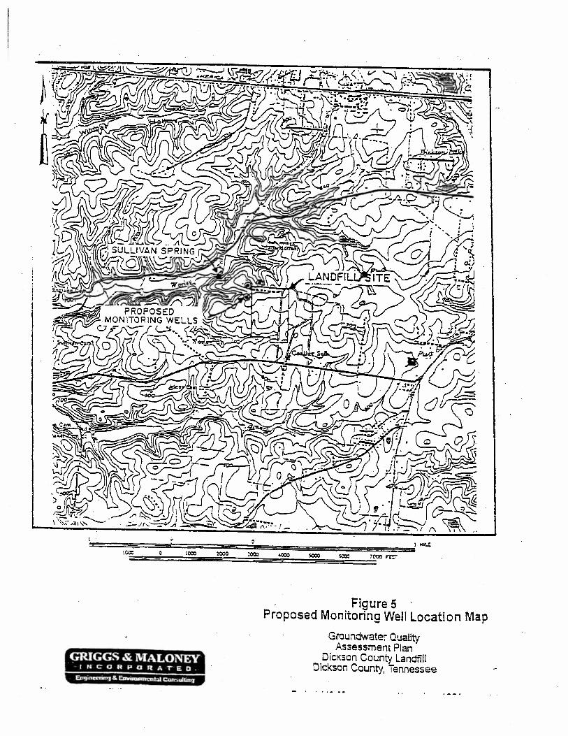
Figure 5 · . Proposed Monitoring Well Location Map
Groundwater Quality Assessment Plan ·
GRIGGS & MALONEY NCORPORA&ED-
Dickson County Landfill Did<.son County, Tennessee
Novv.tiJt:R. 1994
At each ioc:ation, the monitoring well 'Will be installed in the zone of groundwater whichindicates containination, or if contamination is not indicated, in the zo~e of bedrock aquifer which indicates the highest yield. If contamination is detected at any of the wells, it is expected that additional weUs will be necessary.
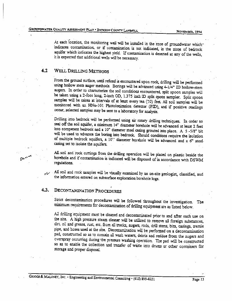
4.2 WELL DRILLING METHODS
From the ground surface, until refusal is encowrtered upon rock, drilling will be performed using hollow stem a.uger methods. Borings will be advanced using 4-l/4" ID hollow-stem augers. In order to characterize the soil conditions encountered, split spoon samples will be taken using a 2-foot long. 2-inch OD, 1.375 inc.h ID split spoon sampler. Split spoon samples will be taken at intervals of at least every ten (1 0) feet. All soil samples will be monitored with an HNu-101 Photoionizarion detector (PID), and if positive readings occur, .selected samples may be sent to a laboratory for analysis.
Drilling into bedrock will be performed using air rotary drilling techniques. In order to seal off the soil aquifer, a minimum 14" diameter borehole will be advanced at least 2 feet into competent bedrock and a 10" diameter steel casing grouted into place. A 5 -5/S" bit will be used to a.dvance the boring into bedrocl;. Should conditions require the isolation of multiple bedrock aquifers, a 10'.' diameter b«;~re!lole will be advanced and a 0' steelcasing set to isolate the aquifers.
AJl soil and rock cuttings from the drilling operation will be placed on plastic beside the borehole and if contamination is indicated will be disposed of in accordance with DSWM regulations.
¥"'v' . All soil and rock samples will be visually examined by an on-site geologist, classified, and the information entered on subsurface e:tploration borehole logs.
4.3. DECONTA.J.mNATION PROCEDURES
Saict decontamination procedures will be followed throughout the investigation. The minimum requirements for decontamination of drilling equipment are as listed below.
All drilling equipment must be cleaned and decontaminated prior to and after each use on the site. A high pressure steam cleaner will be utilized to remove all foreign substances, dir'".., oil a.'ld grease., rust, etc. from all trucks, augers, rods, drill sterns, bits, casings, tremie pipe, and hoses used at the site. Decontamination will be performed on a decontamination pad, constructed so as to contain all wash waters., debris and residue from the augers and overspray occurring during the pressure washing operation. The pad will be constructed so as to enable the collection and transfer of wiste into drums or other containers for storage and proper disposaL
Gtuoos &: MALoto.TI, J:Nc. • Engine:ring and Environmental Consulting • (615) 895-8221 Page .lJ

, .....
Nova.-tnEil. 1994
To clean the drilling equipment the following procedure will be used:
l. Wash with hot water from a high pressure steam washer. 2. Rinse thoroughly with hot tap water or steam, if available. 3. All wash· and rinse water used in the decontamination process will .be coileaed. for proper disposal according to. current rules and regulations. 4. After each cleaning event, the equipment will be allowed to air dry, and then checked with the HNu PID for evidence of vo!arile organics, and visually for cleanliness.
4.4. WELL CONSTRUCTION METHODS
4.4.1 SINGLE CASED WELL INsTALLATION PROCIDUR.E.S
· The casing and screen will be constructed of two (2) inch LD., pre-cleaned, flush threaded, Schedule 40 PVC. The screen will be ten (10) feet in length and will have 0.01 inch factory milled slots. The well screen 'W111 be terminated with a threaded end cap and the casing will be terminated with a locking, watertight cap. Should preliminary sample ·screening results indicate high levels of contamjnarion, four (4) inch diameter wells may be installed for potential use as recovery wells.
· The annular space between the well screen and the borehole wall will be filled with a filter paclc to a depth of approximately two (2) feet (minimum) above the top of the screened Section. A weighted tape will be used to help prevent bridging and ensure the proper placement of the filter pack. The filter pack will consist of clean, washed, well sorted silica sand.
A filter pack seal of at least two (2) feet of bentonite pellets will be placed immediately above the sand. A weighted tape will be used to help prevent bridging and ensure the proper placement of the filter pack seal. If the bentonite seal is placed above the water table, two gallons of potable water will be used to hydrate the pellets. A minimum of 1 hour will be allowed for the pellets to hydrate.
The re::1:lining anr.u1ar space, from the to? of the filter pack seal to 'Within two feet of the s;6::~ ..... ~~1. '=~ sn~~ ·vif;!::. 'ce:.~-:::::~..':2:::~::! gr~l.!t. T:J.e g:"'JL!: will consist of a mixture of Portland cement and 4-6% powered bentonite rcixed to a density of 13.5 to 14.1 !bslga.llor.. A tre:nie pipe will be used to place the am1ular grout.
The final two feet of the annular space will be filled with concrete and a locking above gr~und steel protective cover will be set into place. The concrete apron around each well will be sloped so that surface drainage will be diverted. Each monitoring well will be clearly marked as a monitoring well and numbered. . Figure 6 presents a diagram of a single cased monitoring weU proposed for use at the site.
- · -· · GRlOOS &: MALo~n, INc. • Engineering and Environmental Consulting • (61S) 895-8221 Page 14

0 ·- •• : • •
. ·
GRIGGS & i\'IALO~EY I tt C 0 n P 0 ~ A T E Q
. LOCKING PROTECTIVE COVS
--- CON~E:TE: PAO
GRACE
~---CEMENT/BENTONITE GROUT
~---· se:NTONITE SEAL <MIN. 2ft THICKl
;::1-4~--- SANO PACK
ICIXX~:..;.:;-----· z'' PVC W~ SCRE£N (0~0~) . :'0 11. LENGTli \
·.:Aiiiiii~+---- PVC BOTTOM CAP .i I
. Figure 6 · · .Single Cased Monitoring Well
Construction Diagram . .
Grnundwater Ouaflty Assessment Plan .
· Dickson County Landfill Dickson County, Tennessee
November, 1994
GR.ot.rxowAnR QUA.LITY AssESSMEi'<r PU!'l• DtCKSOI'f Courrrv L\NDFTLL NoVIt...,.ruER. 1994
.. - i I
I .
·;t !f./ c..
d !~~~·
I i
!
, I I ·
/
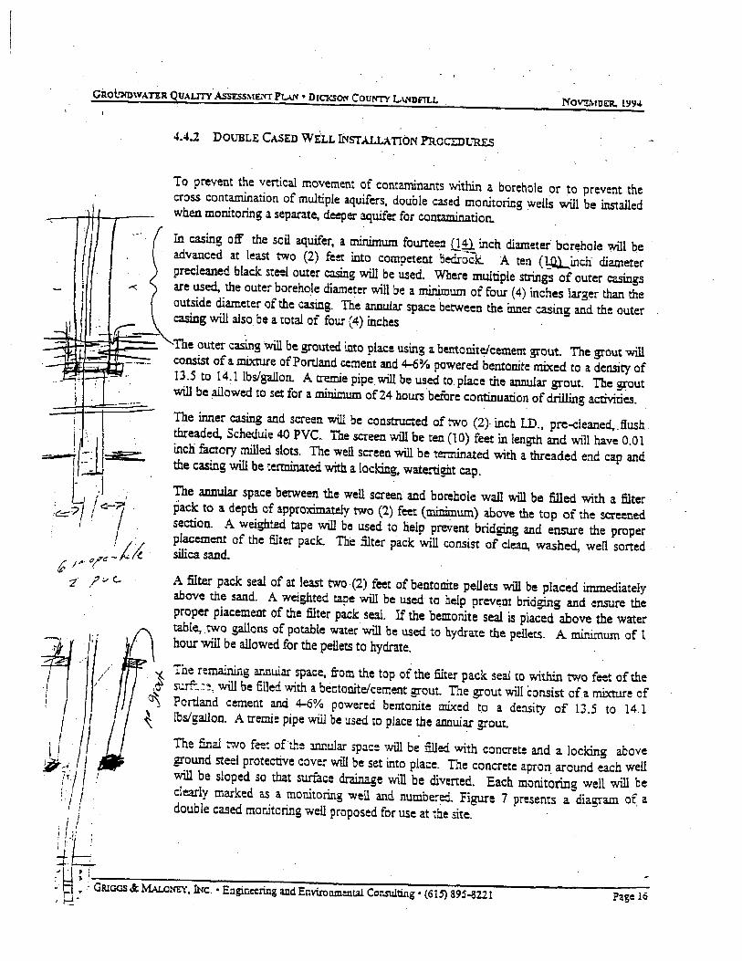
4.4.2 DOUBLE CASED Wir.L !NSTA.LLATION PROCEDURES
To prevent the vertical movement of contaminants within a borehole or to prevent the cross contamination of multiple aquifers, double cased monitoring wells will be installed when monitoring a separate, deeper aquifer for contamination.
In casing off the sail aquifer, a minimum fourteen Q;U. inch diameter borehole will be advanced at least two (2) fe~ into competent bedroCk. A ten (I::Q.L.iflch diameter precleaned black steel outer casing will be used. Where multiple strings of outer casings are used, the outer borehole diameter will be a minimum of four ( 4) inches larger than the outside diameter of the casing. The a.nnu1a.r space between the inner casing and the outer casing will also be a total of four (4) inches
The outer casing will be grouted into place using a bentonite/cement grout. The grout will consist of a mixture of Portland cement and 4-6% powered bentonite mixed to a density of 13.5 to 14.1 lbs/gallon. A tremie pipe. will be used to. place the annular grout. The grout will be allowed to set for a minimum af24 hours before continuation of drilling activities. The inner casing and screen will be constructed of two (2} inch LD., pre-cleaned,. flush threaded, Schedule 40 PVC. The screen will be ten (10) feet in length and will have 0.01 inch factory milled slats. The well screen will be tenninated with a threaded end cap and the casing will be terminated with a Ioclcing, watettight cap.
The annular space between the well screen: and borehole wall M1l be filled with a filter pack to a depth of approximately two (2) feet (~urn) above the top of the screened section. A weighted tape will be used to help prevent bridging and ensure the proper placement of the filter pack. The filter pack will consist of clean, washed, well sorted silica sand.
A filter pack seal of at least two-(2) feet of bentonite pellets will be placed immediately above the sand. A weighted tape will be used to help prev~nt bridging and ensure the proper placement of the filter pack seal. If the bemonite seal is placed above the water table, two gallons of potable water.will be used to b.ydrate the pellets. A minimum of 1 hour will be allowed for the peilets to hydrate.
The remainir1g ar.nular space, from the top of the filter pack seal to within two feet of the ·l s-.:.rf:.~~, -will be filled v.rith a bentonite/cement grout. The grout will consist ofa mixture of ~ Portland cement and ~% powered bentonite mixed to a density of 13.5 to 14.1 ~ lbs/gaJlon. A tremie pipe will be used to place tile annular grout.
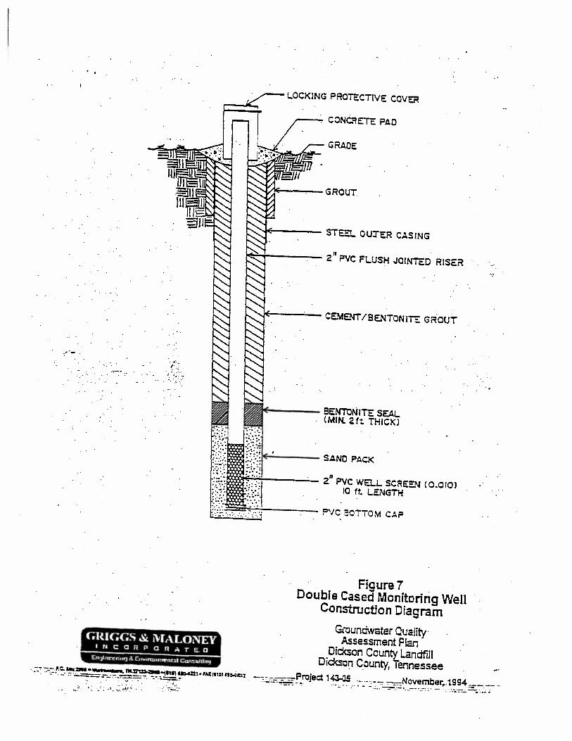
The fir.al two fe~t oft.1~ mnular spac: will be filled v.rith concrete and a lacking above ground steel protective cover will be set into place. The concrete apron_ around each well will be sloped sa that surface drainage W11l be divened. Each. monitoring well will be clearly marked as a monitoring well and number~ Figure 7 presents a diagram of a double cased monitoring well proposed for use at the site. I IJ! '
db_ . : ~ _: .i GR!o<JS .§;MALo""', It«:. • Enginoering and En.U.nmonlal CDnsulting • (61-'J 895-8221 Page 16
..
.... .,. . .. ·.
GRIGGS & i\lfALONEV IUC:ORPORAT E. D
. !..OCKING PROTE:CTIV~ CCV~
GRADE
JoE----..;.- CEMENT/BENTONITE GROUT
~--- BENTONITE SEA!.. (MIN. 2ft THICK)
~---- SANO PACK
ICX¢C+E-~---- 2." PVC WELL SCREEN CO.OIOJ 10 ft. !..ENGTH
·· Figure 7 . · Double Cased Monitoring Well
Construction Diagram
Groundwater Quality· Assessment Plan
Did<son County Landfill Dic:ksc~ County, Tennessee
.,
-.: -.,.:-:..-P.0.._2:1M•- a ""~-11,1l...::ZI•'Allmtn~cn ..,.--:,-,-=-::-=-Project 1~ ...... ,-..,.... ~Novemberr.t994 _-::-. -- .. -.... .... ._ •. __ -::-:.:....:..._ ___ ...:.-:. ... ~--..::-. ~-- - :·· . .:_.~ · ···-·-·~ -- ~· . ···:_ ·· :·.- -.~ .. -=--.· -~---~-·.:--..·.·- · ; ~;-..-.·::-...;.-_·.~;,; ;....:= -: •.: ·./: - ~ .... :_,_.._,_... . ·: ·:~:: .. •
WEll In No.: -.:: ... 1
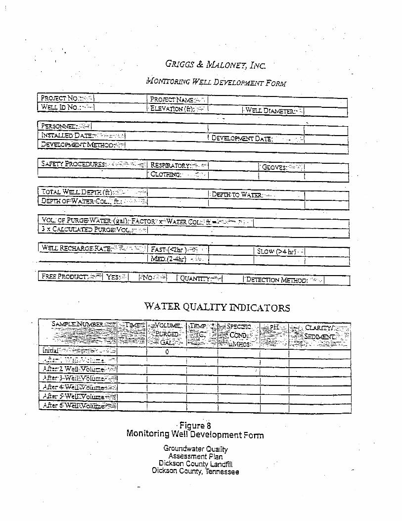
GRIGGS & NfA.LONEY, lNC.
i¥fONITORiiVG W_;u DEVELOPMENT FORM
l PROIECTNA!Y!E',;:., ··, I
. ··I . . -~ ..
'·G- ., .. -,.·! 1 L.OVC:s:· .. ·:: · ·': I' Cl.OTF.ING:. .... . •. I I I
• .
I Stow (>4- hr)' · .: I I I
"'rVATER QUALITY INDICATORS
l.ft,._ ... , .. ~-:r::e'l'·Vio"l·u· ,:, .. ,;..':,:,;;{! I ·1 • --• _. •'fT 1:: " .... • -·'-• -~ •
·Figure 8 Monitoring Well Development Fonn
Groundwater Quality Assessment Plan
Dickson County Landfill Dickson County, Tennessee

• c NO\"E."w(BER. 19'J4
4. 7. GROUNi:>WATER SAMPLING
Groundwater sampling includes the measurement of free phase product, static water level measurements, calculation of standing water volume, evacuation of the well, collection of the sample,. and decontamination of the. sampling equipment. The "Sampling and Analysis Quality Assurance I Quality Control Plan" included in Appendix B presents the details of the sampling and. analysis process and will be adhered to during the performance of all groundwater sampling and analysis. · · ·
After developing the newly installed monitoring wells, the wells will be allowed to stabilize fur a period of at least seven (7) days. Groundwater static water level elevations will then be measured. All water level. measurements will be referenced from an established and documented point on the top of the well casing. The measurements will be correlated with mean sea level darum and measured to the nearest 0.01 foot.
After the water level measur~entS are performed in all weii.s at the site, each well will be purged and groundwater samples collected for submittal to the laboratory for analysis. Monitoring well purging and sampling forms· will be completed for each purging and sampling event for each well.
Samples will be collected for analysis in the order of volarilintion as foUows:
1. . Volatile Organics
2. Extractable Organics
.. Pesticides and Herbicides .J.
4. Dibenzofuransldibenzo-p-dioxins ·
S. Mercury
6. Metals
- Cianide
9. i'H and Cond.u~vity
Initially during well drilling activities, preliminary groundwater sampling will be performed using either HydroPunch sampling methods, temporary well installations, or sampling from the open bedrock borehole. The preliminary sampling will be used to determine the proper depth to screen the wells. Representative samples will be obtained and submitted to a laboratory for nish (24 hour) analysis. ·
GRloos & MALoNEY, INC. • Engille:rillg and Environmental Consulting • (615) 895-8221 Page !0
. ,,...
Novn.mnt. 1994
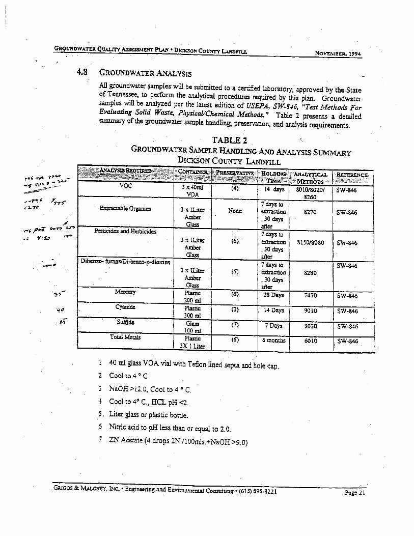
4.8 GROUNDWATERANALYSIS
All groundwater samples· will be submitted to a certffied laboratory; approved by the State of Tennessee, to perform the analytical procedures required by this plan. Groundwater samples ....wi be analyzed per the latest edition of USEPA, SW-846, "Test Methods For Evalllating Solid Waste, PhysiCJll/Chemical Methods." Table 2 presents a detailed . summary of the groundwater sample handling, p~e..-vation, and analysis requirements.
TABLE2 GROUNDWATER SAMPLE HANDLING AND ANALYSIS SUMMARY
DICKSON COUNTY LANDFILL
voc 3 X40111i (4) I 14 days 8010/8020/ VOA 8260
E."tt:raCtablc Organics
Total Metals
3 :t !Liter Amber Glass
3 x !Liter Amber Glass
j :t ll.iter A.1nber Glass
Pla$ti.c 200 ml Plastic JOO ml Glass 100 ml Plastic
jX 1 Liter
I
None
(6) .
(6)
(6)
(3)
(1)
(6)
7daysto extr:lCtion 130 days after 7daysto
,e:a:raction '30 days after· 7 days to e:ctraction • 30 days after 28 Days
14 Days
7Days
6 montllS
1 40 ml glass VOA vial with Teflon lined septa and hole cap. 2 Cool to 4 o C
.3 NaOH > 12.0, Cool to 4 o C.
4 Cool to 4., C., HCL pH <2.
5 . Liter glass or plastic bottle.
6 Nitric acid to pH less than or equal to 2.0. 7 ZN Acetate (4 drops 2N./100mls.+NaOH >9.0)
&270
8150/SOSO
8280
7470
9010
9030
6010
SW.-346
SW-&46
SW-346
SW-M<i
SW-346
\sw~
SW-346
SW-346
.. G;uaos &: MAL.ol-IEY, INc. • Engineering and Environmem.a!Consulting •_ (615) 395..8221 Pag~ 21
l I \ i '
Novnmn. )994
4.9 SAL\QLE LABELING ANn HANDLING
All samples will be handled as prescribed by methodology set forth in the latest edition of USEPA, SW-846, Test Methods For Evaluating Solid Waste,· Physical/C!temical Metltods.
The sample label will contain the following ·iriformarion:
• Project location and project number • Sample location, borehole or monitoring well number. or depth • Method of collection
• Date and time of coUection
• Samplers identifying name or i.oitials • Sample type • Analysis requested
• Method of preservation
An example of a sample label is included in Appendix B. In addition to sample labels, sample seals ma.y also be used to assure the integrity of the sample:~. A ty-pical sample seal . is also shown in Appendix B.
4.9.1 SAMPLE PACKAGING AND SHIPPING
Samples will be packaged to insure physical as well as chemical integrity. Samples will be delivered to the laboratory as soon as possible after sampling, preferably on the same day. If samples must be shipped by con;unon Carrier, use of next day service is required.
Prior .to transport or shipping, the cooler v.ill be packed with shock absorbent material to prevent breakage of the sample containers and prevent the coolant from shifting. Appropriate Chain-of-Custody documentation will be enclosed in the cooler with the samples. and the lid will be secured and sealed. The exterior of the cooler wu.l be labeled _:.:..-'-a,.._" :-·· ~·'·;_,"_ .. ,: .:._, .:..:..,,..,_..,. ~ .. d •"e ... .;,.:,., •.. ·o be shipped to and the total ,'¥ ................ ...-_" ...... - -'-~ _.,.., -"" _..,..., _,,..._~ tJ ..... ,.,.,.!. L.U. a.w.'""' ;;..l~ L 1 weight of the package. Warning labels will be affixed noting "THHS SIDE UP" and '"~-\Gil..!" ::.-:C. ~y !!=j:::priate ha""...,-d.ous warnir.g.
4.9.2. SAMPLE. CHAIN-OF-CUSTODY
Because the samples collected from the investigation may be involved in legalistic proceedings at a later time, Chain-of-Custody . documentation of all samples must be maintained. A Chain-of-Custody is required anytime the sample leaves the custody of the sampler. The possession of sampies from the time of collection must be traceable.
GlUOOS & MALoNEY, INc. • Engin=ring and Emitanmental Consulting • (61S) 8.95-8221 Page 22
Novn.tBG. 19CJ4
A typical Chain-of-Custody form is inch1ded in Appendix B. The form must be filled out-. completely, legibly, and accurately and accompany the sample at all times for .. documentation of the sample handling. When common carriers or shippers are utilized to ship samples to the laboratory, the receipts and shipping manifest must be attached to the Chain-of-Custody to complete the chain. When samples are split between t-Ho or more parties, a. separate Chain-of Custody shall ~e prepared and accompany each sample. .
4.10 SAMPLING QUALITY AsSURANCE I QUALITY CONTROL
Trip blanks. equipment blanks. field blanks. split samples, and duplicate samples are examples of quality assurance/quality control (QA/QC) sampling requirements. QAJQC samples are handled, packaged, shipped,· and analyzed in the same manner as the regular . soil and groundwater samples. QA/QC samples are introduced into the total measurement system as a means of control and evaluation of the level of conwninarion and variability of results as contributed by potential artifacts and interferences arising a.t any point in the measurem~nt process.
QA/QC samples are designed to measure:
l. The integrity of the sample container and sample equipment cleaning process;
2. The actual process of sample collection;
). · The purity of the sample preservatives and additive reagents. and chemicalS;
4. The influence of the site's environmental conditions on the samples;
5. Cross contamination of samples due to improperly cleaned sampling equipment; and.
6. Indeterminate art:i:f.lcts intrqduced during sample transport from containers. · · preservative3, cleaning agents, and sampling equipment.
Table 3 summarizes the number and frequency of the QA/QC sample collection.
. GR.I?G~ ~ ~. L.'IC. • Engineering aod Environmental. Consulting • (615) 895-321+ Page23

GRbtJI'IDWATER Qu.u..rrv A.ssESSi\IENT PUN • DtcxsoN courtTY I..\l'romL .,
4~10~ DUPUCATE SAMPLES/SPLIT SAMPLES
Duplicate samples are utilized to monitor the ability of the sampling procedures to produce reproducible r~sults and to provide the laboratory ·with sufficient sample to perform laboratory matrix spike and duplicate sample analysis. Duplicate samples are essentially identical samples. They are collected, preserved, handled, shipped, stored. and amlyzed in the same manner as the regular samples.
One duplicate sample will be collected for each sample set of ten (1 0) samples collected for submittal to the laboratory. ·
Split samples are duplicate samples split between two or more parties for separate analysis by unrelated laboratories.
4.10.4 FIELD BLANKS
Field blanks are utilized to evaluate the sample container filling procedure, the effectS of environmental contaminants at the site, purity of preservatives or additives.
Field blanks are prepared in the field, on-site, by filling appropriate sample containers with DI water and adding appropriate preservatives and additives as required. The field blank sample is then grouped, handled, stored, and transponed with the true samples collected at the site. ·
Field blanks will be collected at the rate of one (1) sample for each twenty (20) samples corrected.
4.11 SURVEY FOR STREAMS,, SPRINGS, AND WELLS
In order to identify possible discharge points of groundwater from beneath the landfill, the investigation will incfude · a Stm'ey to identifY ·all streams and springs in the area. The survey will include the identi:fication of all domestic and/or commercial water uses within at least a one-mile radius of the site. Further testing of samples from the offsite streams, springs, or wells may be recommended.
4.12 ADDmONAL PHASES OF THE 1~STIGATION
Upon conclusion of the initial phase of monitoring well installarions, sampling, and survey for springs, streams, and wells in the area, it is expected subsequent phases of investigation will likely need to be performed to delineate the full extent of contamination at the site, and to better characterize the area hydrogeology.
GRlOOS ct. MALoNEY, fi-le. • Engine:ring and Environmental Consulting • (615) 3~5-8221 Page 25
. GRtJUN'OWATER. QUALITY ASs!S.SM!.NT PLAN • DrCKSON CoUN"fr L\l'fDFTLL NoV£MDER. 1994
The subsequent phases of investigation may include such activities as aqditional well installations, slug and/or pump testing of weils. sampling of other springs, streams, or wells in the area, and inj~ons of dye to characterize fiow directions. ·
Since the exact nature of the need for subsequent investigation cannot be known until additional work is completed, the scope of work for each additional p~e of investigation will be submitted as an Addendum to the Work Plan prior to performance of the work.
5.0 REPORT OF FINDINGS
Upon completion of the monitoring well installation and sampling, and receipt of all laboratory testing results, a report will be prepared which includes the following: ·
1) Documentation of all monitoring well drilling, install.ation. and sampling activities. 2) Laboratory analytical reportS of the groundwater sampling results. 3) Characterization of the groundwater potentiometric ~e elevatiollS and flow directions. 4) Results of the well, spring, and stream survey. 5) Results of any additional hydrogeologic testing. 6). Reco~endations for additional phases of investigation, if necessary.
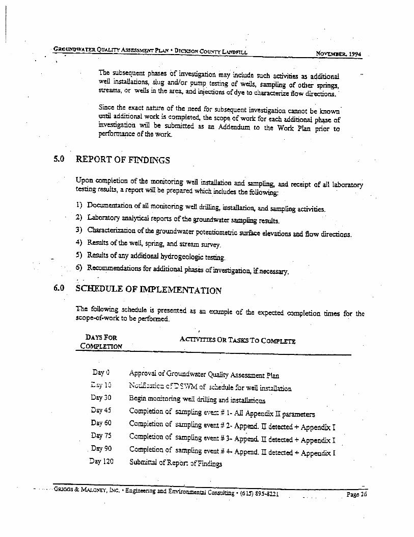
6.0 SCHEDULE OF IMPLEMENTATION
The following schedule is presented as an example of the expected completion times for the scope-of-work to be performed. ·
DAYS FOR COMPLETION
DayO
I:ay lC
Day 30
D<cy 45
Day60
Day75
. Day 90
Day 120
ACTIVI'I'IES OR TASKS To COMPU'I'E
Approval of Groundwater Quality Assessment Plan ~l,jci.EcJ.tic::::. cf'Ds~mvr of sc~edule for weil ins".2llation Begin monitoring well drilling and i.nstalla:tions Completion of siliilpling eve=.# 1- AJl Appenc:llx II parameters Completion of sampling event # 2- Append. IT detected+ Appeoctix I Completion of sampling event # 3~ Append. II detected + Appendix I Completion of sampling event# 4- Appe:1d.ll detected+ Appendix I Submittal ofReport ofFindings
· GRlCiCiS & MAL.c~. l.Nc. • Engineering and Envi.roil.lllental Consulting • (615) 89S-822l Page 26
NoVEMBD. 19914
7.0 REFERENCES
Bracney. Michael W., Ground Water in the Dickson Area ofthe Western Highland Rim gf Tennessee. U.S.G.S. Water- Resotirces Investigations 82-4088 (Nashville, TN, 1984}
.. ATEC Associates, Inc., Geotechnical and Hvdrogeologic Inyestigation Proposed Landfill Site forDic!sson County. Tennessee. (May, 1992)
Gardener Engineering, ~ickson County landfill!Balefill Groundwater Contamination Problem" (September, 1994) .
· · . GRlOOS &: MALoNEY, INc. • Engineering and Enmn.mentai CQnsulting • (61.5) 89S-:8221 Page 27
APPENDIX A
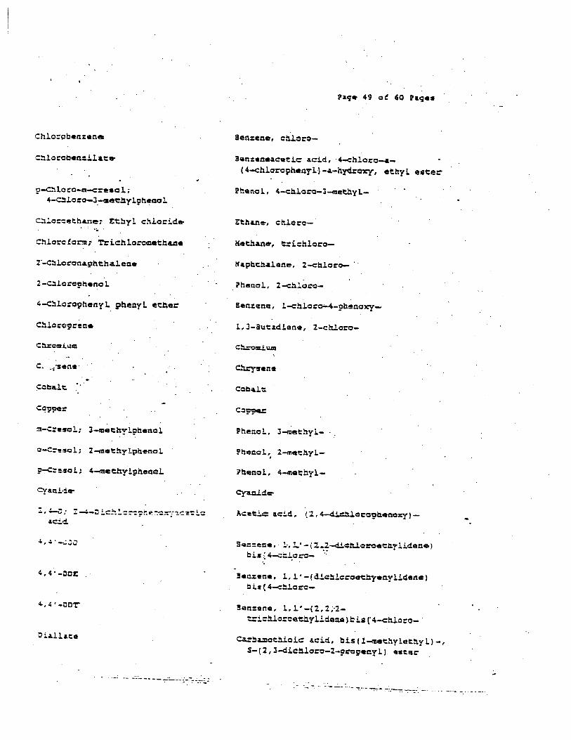
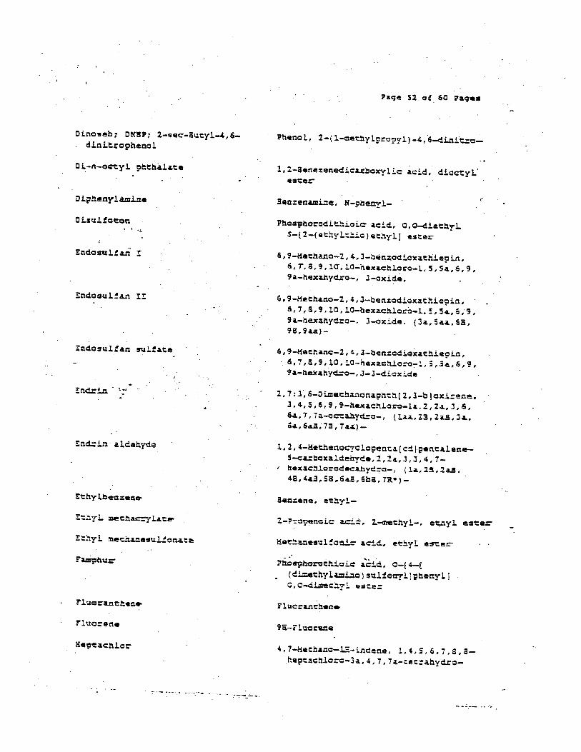
APPENDIX IT. - GROUNDWATER MONITORING LIST. ·-·-.
'i'
--:--.-:--. -•••• •• -.:. - __ ... ' •• - ---· -- - •• - .... -- .... ·- - w •• ·-- • -- -· - :..·--·. ·.- . -. ... -·-. --·.- .
~~~locc-m-e:eeol; 4-C::lo:o-J_-aaeel:lylpheaol
C~lo:cethan~; Ethyl chlocid~ ... Chloro!o~t TricblorQ=eCb&ae
C:U::c:ari.~:m
c:=be.le •. ·
o-c=esol; 2-methylphenol
?~=esol; 4-meehylpheaol
4. 4 • -ooz:
~. 4 ·-oc-r
·- ..::..·------~:_..... __ ·-:~:-:".:._~.:.
Ben:ene~eeeic acid, ·4-ehloro_.-( 4-chlorophenyl·l-•-nydJ:axy, ethyl. e•ter
?henol, 2-ehloro-
Phenol., J-n~ethyl- · .
Phenol, 2-methyl.-,
~~enol, 4-metbyl-
3-e::::ene, l·,l..' -(2.2-c!!.ett.lo:oet:hylicieae) bi• ( 4-c::.l..o=- ·.· . .
!eazene, l,l'-(die~loro«e:yeaylidene) b i.a ( 4-::!:loro-
!en:ene, l, l' -( 2., :2. ;·:2.~iehloroeuylidena) .t: b (' 4-cttl.oc-o- ·
ea==amoehioic aeid, ~is(l-met:hylethyl)-, S-( 2, 3-<li.ettloro-2-pro;eayl ). ester
--- -- ... - """':,-·• ~:-: :-:.-~ -=-~-- -- --

Oiben:(&,h}&nehracen~
0 i.l:2:-amcc:hla:QIZieth.a.a.e; Chlc z:cci.l..b ri::uncmat:h..ae
L 2-0 Ll:u:·omo-3-<:hloC'c:ISJ:Cp411e; OSQ
L.l-Olbr~~eh&na; tthylan~ dib:~de; ~B
Ol-n-b~eyl phehala.t~
o-Oic:~o:cben:ana;
1.2-0ic:hloz:aben:eae
~-O~c:~laz:aban:ene;
l,J-Oiohloz::ben:ea.e
?-0 l.e!:!la·:eben::sne: l.~~oLohlo:~o~n:eae
J,J·-oichlaraban:ldine
.l,l-Oi.c:oloroeeha.ne; !:thyl.cU.dea~ ohlarida
1,2-0ichloroeeha.ne; Ethylen• ~.!.c:!:!:.l.a::!.~e
l,l-O!.c~o:Qeehylaa.a; Vinylidau• ~=l~=~:~; l,l-Ci:~1c::ee~en~
cia-1,2-0ichlo:aeehylene; c.!.•-1,2-0ic:~~==:~e~ena
e:ans-1,2-0ic:hlcroatnylene t:aas-1,2-Diohla:oathea•
2,6-0ic:hloz:c:phenol
Paqe SO of 60 Paqes.
Oi.ben:.( ~,h.] &ntlu:4cena·
0 iben:o fw:a.n
1, 2-ien:anedie&.::oxylic:' ~c:id; cti.bueyl. aste:
. 3en::ene. 1 .• J-<i.ic:!U.oro-
aen:ene, 1,4-dichloro-
(l,l'-iiphenyl]~,4'-d.i~•. 3,3'-dic:hlaro-
1
~thane, 1,1-d.ic:~oro-
Ethane, l.l-dic::la:o-
tthen~, l,2~c:loro-,(t)-

l,2-0ichlo~op~op≠ Prcpy lane- ciicb..loride
l,J-Cichlo~o9ropane;
TrLmethylene dichloriae
2~2-0ichlo==9~op~e; rsopropylid•n• c~lorici•
Oieir:l:!yl !?hc.!la.la.ce
o,o~oieehyl. o-~-9~a.•inyl-paos. phorc~~leⅇ ·~hlonA%i~
0 imet.hca.ce
cn-Oi.e..!.r:=cl:en:ane
" , .s-o i.:l..!. ~-o-<::-e •Q l: 4, i-Di.A.i.t=o2-=•thy lphe.t11:rl
. . ·- -- - -.~- "':"'.- '";- ··-
• i'aqe Sl .ot 60 hqes
Propane, 2,2-dichloro~
l-Pro~ne·, l, 3-di.chloro-, (%)-
2,7:S,6-0imet:~&nona.pheh(2,J-b)cx~ins, J,4,s,6,~,9-hexa.chlo~o-la.,l,2a.,J,a.iia, 7,7a-a~ahyC:o-, (laa.,2B,2a.a.,Ja,sa, lia.a., nr, 1 a.a.J-
·t,2-aen%en~cLrboxyLic ~c~d. d..!.~thyl ener.
?nospho~oe~oi: acid, 0,0-dleehyL o-9y:a:~yl ester
~nosphorod~~oic ~cid, o.o-d~echyl S-£2-(met.hyl~o)-2-oxQet:hyl) e~ter
( l, l' -Bi;rhe:ry!.) -4,4 • -<iiamine; J, J 'c:U.methyl-
?~eJlo.l., 2, 4-oc:.!...n..!.t:o-
!enxene, 2-ma~hyl-l,J-dinit=~-
Oinoseb: O~SP; 2-sec-au~yl-4,6-dinit.rophenol
Diphenyl.tm.ille
OisuJ.fot:on ·~
~ndosul!a..n I!
!ncir!.n · ~ •·
!:net.:: i.."l a lde!:l.yde
tthy lbe::eae-
rluorerte
1,2-Sene:en~ic~=oxyli= acid, diocty~· est:er-
Ben:ettCLmine, N-pheayl-
P~ospho~odit~ioie acid, O,o-diet~y~ S-(2-(et~yl~~io)echyl) ester
6,9-Methano-2,~,3-oen~oaioxa.thLepLn, 6,T,a,9,lcr,lO-nexachlo~o-L,5,Sa,6,9, 9a-nexanyd:o-, 3-oxi~a,
6,9-Heehaao-2,4,J-ben:odioxaehie9in, 6,7,S,9,l0,!.0-hexa.chloro-l,!,S«.,6,"9, 9a-nexahyd:o-. 3-oxide. (Ja.,Saa,sa, 9B,9a.a.)-
6,9-Heeha.no-2,~,J-ben:odiox&t~e~in, 6,7,8,9,10,!.0-hexae~oro-l,S,Sa,6,9, C:a.-nexahyd:o-,J-l-dioxide
2, 7: 3·, 6-0i.methanona.ph<:h( 2, l-b )oxi:ena, J,4,S,6,9,9-hexachlo~-la.;1,2a.,3,6, 6a,7,7a.-o~a.hyaro-, (la.a.,l3,2aa,Ja.. 6.a.,6«.a, 7!, 7a~)-
l,2,4-HethenoCJclo9en~a.(c~)~enta.lene-5-c~boxa.J.dehyde,2,2a.,J,J,4,7-hexach~orodec~yd:o-, (la.,25,2a.a. 4S,4a.S,So~643,6oa,7R')-
Sea:ene, e~yl-
?h.r;;stJhoroet-.i.oic acid., o-1 4-( (di=ethyl~o)suJ.foayl]p!:l.enylJ o,c-di=ec~r~ ~a~e=
,.
4,7-Mecbano-~-lndene. !,,,S,6,7,a.ah.epeact11oro-3a., 4, 7, 7 a.-t::et::=a.hydro-
2-tiexanoae; Machyl :ueyl ketone
,.
. 2, S-Ketha.no-2.R-i.nd.eno ( l, l-b foxirene, 2~.3,4,5,6,7,7-he~eachloro-la~lbl 5~Sa.,6,6a.-hex~yd:o-~ (laa,l~B, 2a., s·a, su, sa, 6.a.a)
l, .3-aut.a.c:Ueae-, l, l., 2.1 3 , 4-, 4-h.exa.c::h..l.o ro-
l, .J-eyclcp.ent.a.ciiene-, l, l, J, '-• S, 5-ltexa.el:!.~o=e- ·
ttha.ne, httxa.c:~loro-
. ) l-Prepene, l,l.~2.J,J,J-hex&c~loro-
2.-fiexa.noae·
1-P::-OS~anol,. 2-ceehyl-
l,4,S,S-OLne~onaphehalane, 1,21.3, <4,lO,lO-hexac:::.loC'o-,l,t.,4a.,s,a,aa.:hexa.hyd:o-(la.,4.a.,4aS,Sa,es,aaa)-
l, 3-Bea:CiciiQxc:l le, S- { l-pc:os:reny l)-
L~J,4-Metheno-~-cyclobu~~(cd]p~neLlen-2-one,l.,la.., J,Ja.. 4, S", s I S"a, 5l::l, 6-decachloC'oo~a.hyd:o-·
t.ead.
. l., 2.-!:thaneai.~e-.. N",N"-di=eehyl-N"':~py;~~.rl-X'-{2-c~ienyW:ethyl)-
Sea:en~. l,l.'-{2,1,I, ~iehloroe~ylid.ec~)ci•(~ methoxy-
Methane, bremo-

3-Hethylchol~nthrene
Ha~ayl ethyl ketone; ~; 1-Bu~anone
Hetttyl. iod.ide; i.odcGJet:ha.ne-
Methyl met~anesul!onat:a
Methyl. parat::!tion; :ru:a.th.i.on 111echyl
4-Kethyl-2-~ntanone: Methyl i.sobuty-1 ketone
Methylene c~loride; OLc:nloroateth4ne
!fa.phtha.lene
l-Napb.thy la.GLi.Ae
2-N'Olphthy la.cti.ne·
· Mi.cxa.L
!en~(j]ac:ea.nthrylene, 1,2-dihydro-Jm.ethyl-
2-Sutanone
2-~ropenoL~ a.c~a. 2-me~hyl-, methyl. ester
~et:hanesulfoni~ ~c:id, methyl este~·
Mapht.ha.lene, 2-(llethyl-·
~bosopho~c~oic Acid, 0,0-dlmechyl 0-(4-n~~:ophenyl) es~ar
N a.phtha.l ene-
l, 4-Na.phtha:len:d.i.one
N'ic:Jcel.
!en:ene:, n.it...~-
?h.enol., . 4-n.i.':::!!:l-

Faqe 55 of 60 Paqes
er-N ie=c:uroci.i ;lheny h.m.Lne aen:enami.nt, N -n.i. e:oso-N-pbeny l-
~-Nlt:oscdipcopyl~ine; Ci-n-prapyl- 1-Propan~ine, ~-aLt=a•o-N-~ropyl nitrosamine; N-Nitrosc-K-d.ipropyluti..:le-. .. ..
5-Nic:a-o-tol~idine
E'~::a.cb.ian
~eneac~~oroben:ene
?eneac:nl.o::onit:obeni:ene. :.
?enta~hlarophenol
?heaac:ati.a.
Phenanthrene
Phenol.
?c!. ·::::-:.!.::-:-:..::~.'=~ b i :;her:y ls; ?0•, n.=:C~Q:s.
sat:o.l.e
·-:' .-. ;-.:-:.: ....
?iperidine, 1-nit=osa-
!7-r::ali.d.Lne, 1-ni~asc-
!141Jl%enami.ne, ·2-;nechy 1-S-n.i.cra-
?has9horoenicic &e~d.. O,O-diet:hyl-0-(4-nie:opnenyl) esee~
3en:ene, ~encac::laronit:o-
?henal, ·peneac:!l.lo.ro-
?henanth.::en~
!.'henol
Pbo59h.cu:ocl.i. ..... ~oic: a.c:id, o·,O'-<U.et:Ayl. S-( ( ee!:~:;!.t:!:i.o) m81:hyl. I est e.:
..:.: .. . ....
..,:;,~-~~' ::!.e, ! : S....A-i.c!':.loro-M-{ l, !.~imechyl-2-p~l.)-
l,J-aen:od.ioxale, S-(2-~ropenyl)-
Seleniu'lft'
S.U..ve.c::"
Sllvex; 2,4,5-~
st::yrene-
.. z.~.s-~: z.~,s-~richlc=opheacxy
a.c:eeic:- a.c:iC.
!.,l,l,2-l'el::aC:U.orceth.a.ne
~~~=achlc:oet:Ylece;
~ec:ac::~crce~h•net
?~rc:hloroeehylene
2, J, 4-,·6~Tet:a.C::Uor:ochencl . -
'toluene
l,l.l-T:i~c==•~h&:~; He-;!:-/ !.:::=.!.c~~==.
~~==lc:oe~ylen~: ~=ichlc:~::oet:!:ene
Vaqe 56 of 60 Paqes
Selenium
Silver
Prop~noic acid, l-(l,~.st:ich1orc9henoxy)-
Sen:en~; ethenyl-
Aceeic &c:id. (2,4,!t=i~lorophenoxy)-
sea:ane, l, 2., 4, 5-tet:a.c:hloec-
E:than~, l, l, l., 2-tetra.chl.orc-
tth&ne, 1.1,2,2-tet:ac:h.loro-
i'henol..· 2,!, 4, 5-tet=a.c:!llo:o-
'till
Sen:ene, !lltt:hyl-
!'oxa.pheae-
.· -. ~&tie·,
-· .. l, l; 2.-l::::.i.c:h.loro-

o,o,o-r~iethyl phcsphorothio4te'
•yrr:-Tl:"init:::oben:ene:
V'L:lyl. &c:et:&t:e-• I ·~
.-
tine:
...
., ·- ··---- ··- -·--·-
1'a.9• 57. at 60 Paqea
Phospnorot:hicic acid, o,o,ot::iet!lyLeste::-
Va.n&d.J:.wa:
Ac::eeic: ac:!.d.,. 'et:~enyl. esce:
£t:hene,. cnlc:n:o-
ien:ene, d~thyl-
Zl.nc
· ..
-- : .-···-- ·-· _: .... ~ ---·
l f
. APPENDIXB
SAMPLING AND ANALYSIS .. · QUALITY ASSURANCE/QUALITY CONTROL PLAN .
Q:UALITY ASSURANCE I QUALITY CONTROL PLAN
SA1\1PLING AND ANALYSIS · OF .
GROUNDWATER MONITORil'tG WELLS
....... --- .... ·:_-_--..::; ... -.- . ·-- ......
PREP AR.ED FOR
DICKSON COUNTY
JUNE, 1994 .
GRIGGS & i\'I ALONEY. INCORPORATED
_ ::.ngmccnng & Enwcnme:'lalCon~u!tu-;g
7 45 South Church St., Suite 20S · PO Box: 2968 (37133-2968)
Murfreesboro, Tennessee 37130 (615) 895-8221 • (615) 895-0632 FAX
Ftle Number 143-05
·: - ~-7 · ~- -.- . · ·: . -:- - ---- · - --·-. --'---- . . - · - - · --

APPENDIX A
APPENDIXB
APPENDIXC
UST OF APPENDICES
MONITORlNG WELL PURGING and SAMPLING FORM
SAMPLE LABEL AND CUSTODY SEAL
CHAIN -OF· CUSTODY
GRIOOS &: MALoNEY,lNC, • Engineering and Environmental CollSUlting • (615) 89j-822l Page i
-~-----··--- ' ··:--.--- __ ._...:._;__ ____ -_ :·..:-.. - .. ··- ~ ... ··.- --:--- - -. ----···--· .. ----:--··- ---

QA/QC Sampling and Analysis Plan- Dickson Co. Landfill . November, 1994
QUALITY ASSURANCE I QUALITY CONTROL PLAN SAl'fl»LING AI'ID ANALYSIS
OF GROUNDWATER MONITORING WELLS
1. INTRODUCTION
. This document is prepared for the State of Tennessee Department of Environment and Conse~on, Division of Solid/Hazardous Waste Management to establish Quality Control and Quality Assurance guidelines. .'These guidelines are to be followed throughout the groundwater assessment monitoring period at the Dickson County Class I Landfill
This plan coven the complete process utilized for the coUection of quality groundwater . monitoring samples including the: ·
• measurement of groundwater levels
• detection I measurement of immiscible layers
• purging ofwells
• · .. sample coDectioDr handling, and analysis
• quality control and quality assurance
2. GROUNDWATER LEVEL AND WELL DEPTH MEASURE:MENT
2.1. STATIC WATER LEVEL
The depth to water level in the wells must. be measured to calculate the casing water volume for purging and also for the purpose of determining the hydrological ~~un~--;.r:~:: c!'::.~~::nics.
T.:: stz.ic Wa!::: ~~·1e! in the we!! is meas-...:red prior to the well evacuation. Initial sraric water leve!s are me::..<:'"f.!red r;pic:illy seven to ten days. after installation and de•1e~o?m~~~ ~f t :1~w weU and additional me:!S\lre!lents are performed prior to each purging and sampling event All water leV-el measurements utilized to consuvct a piezometric surface Dla13 must be obtained within a consecutive twentyfour (24) hour period.
Griggs&: Maloney, Inc:. • Engine.-ring and.El!Vironmetllal Consulting • (615) &95-8211 Page 1 .

QAIQC Sampung and Analysis Plan- Dickson Co. Landfi11 November, 1994
2.1. STATIC WATER LE'VEL, Cont'd
The water level elevation will be detennined to the nearest 0.01 feet as measured 'with a water levei meter .. The meter consist of a reel containing a length of weighted, marked fiberglass tape, which has a conducting. probe attached· to detect the air/water interface, and an alarm. · · ·
The water level measurement is performed three (3) times to insure accuracy and water level stability. Always measure the upgradie:n or background weUs first to reduce the potential for cross contamination.
The following procedure will be followed for water level measurement in groundwater monitoring wells.
A) Prepare a "Monitoring Well Purging and Sampling" (:MWP&S) form. (Appendix A) for each well to be measured, and enter all reference information for each well. ·
B) Locate the well identification on the casing and the well elevation reference marie and check against the site .map for ve!incation. If identification or elevation markings are not found on the well, verify the well identification and mark the well with the identification number and an elevation mark. Note the changes on the MWP&S fonn and inform the project ma.nager. If a new elevation mark is placed on the well, a survey must be performed. •
C) Place a plastic sheet on the ground surrounding the well by cutting a slit in a . piece of plastic anQ. inserting over the well. The plastic sheet should be of sufficient size to prevent contamination of equipment and supplies during the water level measurement process.
D) Unlock and open the protectiVe well cover and tb.e well cap. Note the well condition and any odors observed on the MWP&S form. . .
E) Sample the well headspace for volatile organics with an HNU-101 photoionization detector (previously calibrated) and record the ffi.lU reading en tile ~vCW ?.i.5 iorr:-...
F) Put on a ciean pair of unpowdered, disposable gloves. (When gloves become soiled or damaged re?lace with a clean p~). Dispose of used gloves as per instructions !n Section 11. Q_
G) Determine if the water level tape and probe has been decontaminated. If not, wash with soap and water, and rinse with Dr water. Dispose of wash and rinse water as per instructions in Section 11. 0.
---=-G~ggs-~-~-n:y. Inc. • Eng:i.ne-..rl.ng anc1 Environmental Consulting • (615) 395--3221 Page2
QAJQC Sampling and Analysis Plan- Dickson Co. Landfill November, 1994
2.1. STATICWATERLEVE~ Cont'd
H) Check the probe sensor and battery by immersing the probe in water. Note the level of the water on the electrode sensor when the alarm just begins to sound. If the probe operation is normal, proceed with item L If the alarm does not
sound when the electrode tip contacts the water's surface, determine what is causing. the malfunction before proceeding or obtain another water level meter. . . . . . .
!) Lower the probe and tape into the well carefully and slowly. Do not allow the tape to contact the wen casing to prevent da.mage to the tapes surface. Surface abrasions will cause difficulty with later cleaning and decontamination.
l) When the probe contacts the water surface and the alann sounds, retrieve the probe um:i1 the alarm just ceases. Continue lowering and raising the probe until the point where the alarm just begins to sound is determined.
K) Hold the tape against the well elevation mark on the casing.
L) Note and record on the .MWP&S form the distance from the well elevation mark to the groundwater's surface to the nearest 0.01 feet. ·
M) Repeat parts I-L two more· times to verify ·the measurements. If the . measurements are not constant, continue to measure at greater time intervals
until the leveis stabilize. The elevation of the wen minus the distance to the water surfuce is equal to the elevation of the water.
N) To measure the total well depth, lower the weighted tape slowly to the bottom of the well. ·
0) Mark the tape and read at the well elevation reference mark to the nearest 0.01 feet. '
P) Record the distance from the wen e!evation reference mark to the well bottom on the MWP&S log sheet.
Q) Remove the tape and probe from the well being careful not to allow the tape to r-:.!1:: C!'!. the well ?tpe or c~ing.
R) Replace the well cap and lock the well or continue With purging and sampling.
S) If free product or gross contamination are not encountered or suspected, wash the tape with soap and water and DI water rinse after each use. If free product or gross contamination are encountered or suspected, rinse the tape and probe with alcoho~ rinse with water, wash with soap and water and DI water rinse and finally rinse with alcohol and then DI water. The tape and probe must be washed with soap and water and rinsed with alcohol and DI water prior to use in another well.
Griggs~ Maloo.cr, Inc. • Engineering and Environmental Consulting • (615) 895-3221 Page3
,· 'Q(VQC Sampling and Analysis Plan- Dickson Co. Landfill November, 1994
2.1. STATIC WATER LEVEL, Cont'd
S) All wash and rinse water and alcohol rinse must be collected and held for proper disposal according to the guidelines set fonh iri Section l LO ...
3. DETECTION AND SAMPLING OF IM1\11SCIBLE LAYERS
. 3.1. DETECTION OF IMMISCIBLE LAYERS
After opening the well, sample the well vapor space with an HNU-1 0 1 ' Photoionization Detector. It: after opening the well, the HNU indicates detectable levels of organics, a. floating layer is indicated, and must be measured and sampled as set forth in the following section. If the HNU does not indicate detectable levels of volatile organics it will be assumed that no floating immiscible organic layer is present, and work will continue to purge arid sample the wells.
3.2. SAMPLING OF IMMisCIBLE LAYERS
If immiscble layering is detected in any of the wens, samples of the immiscible layer must be collected prior to purging. For fioating layers, samples will be collected with a disposable bailer, .or a peristaltic punip if the layer is Iocited Within ~feet of the surface. For bottom layers a double valve bailer will be utilized.
3.3. SAMPLING PROCEDURES FOR IMMisCIBLE LAYERS
The following procedure will be followed for sampling of immiscible layers in groundwater monitoring wells.
A) Prepare a "Monitoring Well Purging· and Sampling" (MWP&S) form (Appendix A) for each well to be measured, and enter all reference information for each well.
B) Locate the well identification on the casing and the well elevation reference . ~~ie anci c.necK -:::.;..~:.;,;• :0::: ~i•e mag for ver.Ocation. If identification or elevation markings are not found on the well, verify the well identification and
::::!:lc the well witr. •he identi£cation numbe:- and an eleVation mark. Note the changes on the i\tfWP&S form and inform tbe project manager. If a new elevation mark is placed on the wen, a survey must be perlbnned.
Griggs&:. Maloney, Inc. • Engineering and Environmental Consulting • (615) 895-8221 Page4

QAIQC Sampling and Analysis Plan- Dickson Co.·Landfill· November, 1994
3.3. SAMPLING PROCEDURES FOR IMMISCIBLE ~YERS, Cont'd C) Place a plastic sheet on the grotind surrounding the well by cutting a slit in a piece of plastic and inserti:ilg over the well. The plastic sheet should be of sufficient size to prevent contamination of equipment and supplies during the water level measurement process.
D) Unlock and open the protective well cover aild the well cap. Note the well condition and any odors observed on the MWP&S form.
E) Sample the well headspace for volatile organics 'With an HNU-101 photoionization detector (previously calibrated) and record the HNU reading on the MWP&S form.
F) Put on a clean pair of unpowdered, disposable gioves. (When glove:s become soiled or damaged replace with a clean pair). Dispose of used gloves as per instructions in Section 11.0.
G) Determine the static water level following procedures in Section 1.1.
H) Lower a previously cleaned bailer slowly into the well to the interval being sampled. If the layer is only a few inches thick. use an open top bailer and lower the bailer an
I) Raise the bailer to the surface carefully. Do aot allow the bailer or bailer cord · to contact the ground.
J) Remove the cap from the VOA vial, and tilt slightly.
K) Pour the sample slowiy into the vial to avoid spillage and air entrainment, making sure to quantitatively transfer any sediment in the sample. Fill the vial to overflowing to provide for a zero airspace sample, and cap. Invert, tap the vial with a finger and check for air bubbles. Ifbubbles appear repeat the filling process.
:). L:.:e::. ~·~:~:::.;-:. :J..~c 7<.;,r~ ti:e s;r.;:i't ac::~r:.:.::g to ir.str"~:::.;us in Sections 8.0 and 9.0 for sample handling and documentation.
1-i) Repiace the weil cap anci lock ~e well.
N) Rinse the water level tape and probe with alcoho~ rinse with water, wash with soap and water and DI water rinse and finally rinse with alcohol and then DI water. The tape and probe must be washed with soap and water and rinsed with alcohol and DI water prior to use in another well.
0) Wash and rinse all equipment prior to leaving the site.
Griggs &;.Maloney, Inc. • Engineering and Environmental Co.n.sulting • (615) 895-&221 P::~geS

. QA/Q'C Sampling and Analysis Plan- Dickson Co. Landfill November, 1994
3.3 •. SAMPLING PROCEDURES FOR l.MMISCIBLE L\.YERS, CON'T'D
P) All wash and rinse water and alcohol rinse must be collected and held for proper disposal according to the guideliries set for"Jt in Section 11.0.
Q) Dispose of ail conta.mincued materials, gloves, etc. according to the guidelines set forth in Section 11.0.
4. WELL PURGING
. 4.1. GROUNDWATER MONITORING WELLS PURGING
The water standing in the well prior to sampling may not be representative of the in-situ ground water quality. Therefore the standing water in the wen and filter pack will be removed so that fresh water from the aquifer can replace the stagnant water.
If the well is in a high yield formation the wen· will be evaCuated from above the sand pack to draw fresh water up through the well. The most efficient exchange of water in the well is effeaed by .pumping from near the top of the water column. This C311Ses the stagnant water in the casing above 'the filter screen to be evacuated first.
A minimum of three (3) well volumes of water will be evacuated from the well. The capacity for the well to recharge and the draw down of the water colwnn should be noted for future reference.
Low yield wells will be evacuated to dryness and allowed to re1:ha.rge slowly. Whenever full recovery of the water in the well exc~ two hours, samples will be collected as sufficiem water becomes available. Whe:~. the recharge rate is less than · two (2) hours, monitor the water quality (pH, Conducti:vity, and Temperature) until the readings become stable, indicating the well bas been sufficiently purged.
Peristaltic, submersible pur;~. a:~d/or positive gas displacement Teflon bladder f'l411F:i, :!..:~;.;~· ~:~;;cs:.::e ~~::·: ·;.~::2 ·.: ·.::±::::: !O eva.:-..;:.l;~ tbe wells prior to sampling. Disposable polyethylene baliers may be used if free product will not be encountered i.."'l ~he well.
Peristaltic pumps may be utilized when th.e water lift is less t.b..an twenty-five (25) feet At depths exceeding twenty-five (25) feet, submersible purge or positive displacement pumps or bailers will be used. Bailers may be utilized m all weUs, although the limited capacity of the bailer makes their use laborious. When using bailers lower and raise slowly to prevent agitation of the water in the well.
. . . . . 9riggs_~ Ma1oney, Inc. • Engineering and Environmental Consulting • (61.5) 89!i-32ll P::~gc6
.. · QAJQC Sam-pling and Analysis Plan- Dickson Co. Landfill November, 1994
4.1. GROUNDWATER MONITORING WELLS _PURGING, Cont'd
Care will be taken to protect the b~er, pumps, suspension cords, tubirig and cables from contacting the areas surrounding the well. A plastic sheet ;vlll be utilized to cover the ground and well opening area to protect the equipment.
When lowering the pumping equipment into the we!!, the pump and tubing will be supported to prevent it from dragging on the top of the well casing or binding· when being lowered or raised. '
The well may be considered to be evacuated when the water be1:omes dear and sufficient quantity has been evacuated (3x volume of water in the well). Purged water will be collected and screened to determine if it may be hazardous. If the possibility the purged Water contains hazardous contaminant levels which exceed those ·levels which may endanger the health of personnel or the environment.· the · water will be drummed and held for proper disposal by post treannent on site or disposal by certified waste disposal handlers.
4.2. PURGING PROCEDURES FOR GROUNDWATER MONITORING WELLS
The following procedure will be followed for purging ofgroundwater from the monitoring wells:
.A) Prepare a "'M:onitoring Well Purging and Sampling" (MWP&S) form (Appendix A) for each: well to be measured, and enter all reference information for each well.
B) Locate the well identification on the casing and the well elevation reference mark and check against the site map for verification. If identification or elevation marlcings are not fol.flld on the well. verify the weU identification and mark the well with the identification number and an elevation mark. Note the changes on the MWP&S form and inform the project manager. If a new elevation mark is placed on the well, a survey must be performed.
C) Place J. plastic sheet on the ground surrounding the well by cutting a slit in a piece of plastic and inserting over the well. The plastic sheet should be of · sufficient :size to preve:1t contamination of equipment and supplies during the water Jevei m~ement process.
D) Unlock. and open the protective we!l cover and the well cap. Note the well condition and any odors observed on the MWP&S form.
E) Sample the well headspace for volatile organics "With an HNU-101 . · photoionization detector (previously calibrated) and record the HNU reading
en the MWP&S form.
Griggs&: Maloney, Inc. • Engineering and Envi.ronmentai Coo.sulting • (615) S95-3221 Page 7

QAJQC Sampling and Analysis Plan- Dickson Co. Landfill November, 1994
4.2. PuRGING PROCEDURES FOR GROUNDWATER. MONITORING WELLS, Cont'd
F) Put on a clean pair of unpowdered, disposable gloves. (When gloves become soiled or damaged, replace with a clean pair). Dispose of used gloves as per instructions in Section 11.0. · ·
G) Determine the static water level follovling proc:tdures in Section 1.1.
H) Determine the purging method to be followed.
I) Calculate the volume of water in the well from information gathered when measuring the well depth and static water level by one of the following methods:
Depth of well -Depth to water • Height of water column
1) BY FORMUI..A:
·r x h x 7.481 ==gallons of water where: r = radius of the wen pipe in feet
h = h.eiglit of water column in the wen 7. 481 ""' gallons/ cubic foot of water
2). BYWEU.PIPE S1ZE:
a) For 2" diameter wells:
Gallons • 0.1632 (gaJ/ft) Xh (ft)
when h • height of water column in the well
b) For 4" diameter wells: ·
Gallons ... 0.6528 (gallft) X h (ft)
when h ::: heisht of water column in the weU
c) For 6" diameter wells:
Gallons = 1.4688 (gal/ft) X h (ft)
when h = height of water column in the well
Record the purge volume on the MWP&S form.
J) Sample the water in the well and test for pH, specific conductance, and temperatUre. Record results on the MWP &S form.
Griggs~ .. ~~~-~ ~---~~cering and Environmental Consulting • (615) &95-3221 PageS .. -
QAIQC Sampling and Analysis Plan- Dickson Co. Landfill November, 1994
4.2. PURGING PROCEDURES FOR GROUNDWATER MONITORING WELLS, Cont'd
K) Purge the calculated volume of water from the well.
L) All purged water from the wells will be eollected in tanks or drums for later analysis, treatment and disposaL
M) Repeat items J and K two additional times to purge a minimum of three (3) well volumes from the well when the recharge r:tte is sufficient
N) Record all purge times, volumes., and water quality test results on the "MWP&S form.
0) R..insc the purge pump or bailer (if not dedicated) with DI water and combine the rinse water with the purge water for disposaL
P) Wa.c;h and rinse all equipment prior to leaving the site.
Q) Wash the pumps and bailers with soap and water, rinse with DI water, rinse with a!coho~ and finally with DI water prior to use in other wells. Combine the washings and rinse water with the ·purge water for disposal per the instructions in Section 11.0. · ·
it) Samples will be collected as soon as possible after purging, allowing sufficient time for the well to recharge.
S) Repla.ce the well cap and lock the well.
T) Dispose of all contaminated materials, gloves, etc. according to the guidelines set forth in Section 11.0.
5. SAMPLE COLLECTION
5.1. SAMPLE INTEGRITY
To ensure the samole collected is re;Jresentative of the formation, it is important to minimize physically altering or chemically contaminating the sample during the collection process.
Care will be taken to· protect the sampling equipment, tubing and cables from contacting the areas surrounding the well. A plastic sheet will be utilized to cover the ground and well opening area to protect the equipment
Griggs ~,~onc:y, Inc. • Engineering and Environmental Consulting • (6l.S) 895-8221 Page 9

QA/QC·Sampling and Analysis Plan- Dickson Co. Landfill November, 1994
5..2. SAMPLE COLLECTION- BAILER
A bailer is a. long cyQ.ndrical tube constructed of maxerials which will not alter the quality of the sample being coUected. Bailers used will not have glued joints. Bailers used at the site' Vvill be of the disposable, bottom-fill type, constructed of polyethylene. '
The bailer will be lowered into the well by a line into the groundwater where it fills from the bottom. The bailer has a ball, which seals the bottom of the bailer to prevent the water from emptying when the bailer is lifted from the well.
5.3. SMIPLING PROCEDURES FOR BAILERS
The following procedure will be followed for sampling of groundwater in . monitoring wells when using bailers.
A) Prepare a ''Monitoring Well Purging and Sampling" (MWP&.S) fonn (Appendix A) for each wen to be measured, and enter all reference informatj.on for each well.
B). Locate the wen identification on the casing and the well elevation reference mark and check against the site map for verification. If identification or . eievation.markin.gs are not found on the well, verify the well identification and mark the wen with. the identification number and an elevation mark. Note the changes on the MWP&S form and inform the project manager. If a new elevation mark is placed on the well. a survey must be performed.
C) Place a plastic sheet on the ground surrounding the well by cutting a slit in a piece of plastic and inserting over the weU. . T11e plastic sh~ should be of sufficient size to prevent contamina.ti.on of equipment and supplies during the water level measurement process.
D) Unlock and open the protective well cover and the well cap. Note the well condition and any odors observed on the 'M'NP&S form.
E) Sample the well headspace for volatile organics with an HNU-101 ;:;:-Jtoicr;'":-,:::::-. -:~~~:-:Jr (:::-=· . ..:~:.:::::.- :~forared) and record the B:NU reading on the 1\t.f\VP&:S form. Determine ii immiscioie layers are present (Section 2.0).
F) Put on a clean pair of unpowdered., disposable gioves. (When gloves become soiled or damaged replace with a clean pair): Dispose of used gloves as per instructions in Section 11. 0.
G) Determine the static water level following procedures in Section 1.1.
Griggs & Maloney, Inc. • Engineering and Environmental Consulting • (615) S9S-82ll Page 10 •• -- • •--- • ·----•a• - ... · - - -
· QA/QC Sampling and Analysis Plan- Dickson Co. Landfill November, 1994
,._
5.3. SAMPLING P&OCEDlJRES FOR BAILERS, Cont'd
H) Purge the weU of the required three (3) well volumes of groundwater or to dryness.
I) Attach new line to a nev~ disposable bailer or use a dedicated bailer for each well to be sampled.
l) Carefillly and slowly lower the bailer to the groundwater surfuce.
K) Allow the bailer to fill slowly with a minimum of water surface agitation to prevent aeration.
L) Raise the filled bailer to the surface while protecting the line from becoming . .
contaminated.
M) Remove the cap from the VOA vial, and tilt slightly.
N) Pour the sample slowly into the vial to avoid spillage and air entrairunent. making silre to quantitatively transfer any sediment in the sample. Fill the vial to overflowing· to provide for a. zero airspace sample, and cap. Invert, tap the vial with a finger and chd for air bubbles. If bubbles appear repeat the filling process.
0) Properly dispose of excess sampie collected from the weU by combining with the purge water or wash water.
P) Labe~ package, and store the sample according to instructions in Sections 8.0 and 9.0 for sample handling and documentation.
Q) Replace the well cap and lock the well.
R) Wash and rinse all equipment prior to leavmg the site and rinse the exterior of all samples.
S) All wash and rinse water, alcohol rinse water, and excess sample must be collected and held for proper disposal according to the guidelines set forth in Scc:O::n.l i.C.
T) Dis9ose of all contaminated materials (bailers, line, plastic sheeting, gLoves, etc.) a,ccording to the guidelines set rortil in Secrion 11.0.
U) Samples will be labeled., packaged., stored, and shipped according to the guidelines set forth in Sections 8.0 and 9.0 ofthi! plan.
V) Complete the required chain ..of-custody and doCilillentation for the sampling.
Griggs&; Maloney, Inc. • Engineering anc1 Etrrironmental Consulting • {615) 895-8221 Page 11
. . QA/QC Sampling and Analysis Plan- Dickson Co. Landfill November, 1994
-.
5.4. SAMPLE COLLECTION- BLADDER PUMP
A bladder pump is a long cylindrical tube with a flexible air operated bladder, constructed of materials which will not alter the quality of the. sample being · collected. Bladder pumps operate by alternately in&ting and deflating the fie:cible bladder to alternately withdraw water from the well and pump the water to the surface.
5.5. SAMPLING PROCEDURES FOR BLADDER Pm£PS
The following procedure will be followed for sampling of groundwater in monitoring weUs when using bladder pumps.
A) Prepare a "Monitoring Well Purging and Sampling" (MWP&S) form (Appendix A) for each well to be meaSured, and enter all reference information:· for each well.
B) Locate the well identification on the casing and the well elevation reference mark and check: against the site map for verific~on. If identification or elevation markings are not found on the well, verift the well identification and mark the. well with the identification number and an elevation mark. · Not~ the changes on the MWP&s form and inform th.e project manager. If a new .elevation~ is placed on the well, a survey must be performed.
C) Place a plastic sheet on the ground surrounding the well by cutting a slit in a piece of plastic and inserting over the well. The plastic sheet should be of sufficient size to prevent conta.m.ination of equipment and supplies during the · water level measurement process.
D) Unlock and open the protective weU cover and tb.e well cap. Note the well condition and any odors observed on the MVIP&S form.
E) Sample the well headspace for volatile organics with an HNU-1 01 photoiociza.tion detector (previously calibrated) and record the HNU reading on the 1v.L'7v?~.5 for:4l. De:~~~ if immiscfole layers are present (Section 2.0).
F) Put on a clean pair of unpowdered, disposable gloves. (When gloves become soiled or damaged, reulace with a ciean pair). Disj)ose of used gloves as per . . instructions in Section 11. 0.
G) Determine the static water level following procedures in Section l.l.
H) Purge the well of the required tbre: (3) weU volumes of groundWater or to dryness.
1) Attach the cgmpressor lines to the gas control box. Griggs&; Maloncy, Inc. • Enginemng and Environmental CollS1llting • (6 I.5) 39S.a221 Page 12 ·. - ~-· .-:·"':""';~_ .. __
QAIQC Sampling and Analysis Plan- Dickson Co. Landfill November, 1994
5.5. SAMPLING PROCEDURES FOR BLADDER PUMPS, Cont'd
J) Connect the battery to the gas control box.
K) Attach the support tine and compressed gas lines from the gas control box, to the previously decontamina:ted bladder pump.
L) Lower the pump and tubing into the well carefully to prevent the tubing from and support cable from becoming contaminated or rubbing on the well casing or protective cover which may damage or conuminate the pump or tubing.
M) When the pump has been lowered to the prescnoed depth, secure the support line and turn on the power and cotni)ressed air.
N) Adjust the gas control box to the desired pump and fill cycle time to optimize the pumping rate.
0) Remove the cap from the VOA vial, and tilt slightiy.
P) Allow the water being discharged from the pump to be slowly discharged into a precleaned 40-ml VOA vial Fill the vial slowty to avoid entrainment of air, m.ak:ing sure to quantitatively transfer any sediment in the sample. Fill the vial to overflowing to provide for a zero airspace sample, and cap. Invert, tap the
·vial with a finger and check for air bubbles. If bubbles appear repeat the filling process.
Q) Properly dispose of excess sample collected from the well by combining with .the purge water or wash water.
R) Labe~ package, and store the sample according to instructions in Sections 8.0 and 9.0 for sample handling and documentation.
S) Remove the p"ump and tubing from the well, bemg careful not to damage the well casing, pump, or tubing.
T) Coli~ ail ·.v·;;~e:- ,:.,;~ -.1e pu~p J.t.-:ci cubing, E:.:sz -wirh potable water (inside a.:.:._; vL.~ic~). c~\k:::::.ing :!! w~t~r d:-ine~ ~I:l t:e pu1np and tubing and rinse waters for proper disposal.
U) Replace the well cap and lock the weU.
V) Wash and rinse all equipment prior to leaving the site and rinse the exterior of the sample container. ·
W) All was~ and rinse water, alcohol rinse water, and excess sample must be collected and held for proper disposal according to the guidelines set forth in ·Section 11. 0.
-· -~ri~ ~Mal~ney, Inc. • Engineering and Environmental Consulting • (615) 895-8Ul Page 13
Q A/Qt ·Sampling and Analysis Plan- Dickson Co. Landfill November, 1994
5.5. SAMPLING PROCEDURES FOR BLADDER PmtiPS, Cont' d 1) Dispose of all contaminated materials (plastic sh~ting, gloves, etc.) according to the guidelines set forth in Section 11.0.
K) Samples will be labeled, packaged, stored, and shipped according to the guidelines set forth in other sections of this plan. .
. L) Complete the reqUired chairi-of-custody and documentation for tb.e sampling.
6. FIELD MEASUREMENT "PROCEDURES
6.1. FIELD l'r'lEASUREMENT PROCEDURE· TEl\1:PERATURE
· The measurement of temperature during the purging and sampling of monitoring wells is required to monitor the purging process. Temperature will be measured by use of a· glass thermometer which is stored in a plastic case.
Samples of water from the well are taken and prior to purging and at intervals durio.g the pw-gi.ng process. The thermometer is iDserted in the sample as soon as possible after withdrawing the water from the well. swirled to mix, and read when the thermometer fluid column has stabilized. ·
The temperatUre is recorded and the sample utilized for the measurement of pH and specific conductance. The thermometer is dried by wiping gently, and stored in its protective case.
6.2. FIELD MEAsUREMENT PROCEDURE- PH I
The . pH of the groundwater sample is determined e!ectrometrically with a combination glass pH electrode. The following procedure will be utilized for pH measurements:
A) Cvliect a fresh sample ofthe groundwater to be tested or use the sample used for the T.e~~rement of ~em!Jet"ature.
B) Measure a."1ci not~ the temperature of a sample of pH=7 buffer solution.
C) Measure anc note the re.::::1per:m.•re of a sa..-nple oi either pH=4 or pH=lO buffer . solutions (to bracket the pH of the groundwa:ter). The temperature of the pH-7 and the other buffer used should be the same. ·
D) Turn on instrument power, select pH mode, remove the electrode protective cover and rinse with DI water.
Griggs & Maloney, Inc:. • Engineering and Environmema.1 Consulting • (615) &9~-3221 Page 14 • -
•4
. QNOC Samt>ling and Analysis Plan- Dickson Co. Landfill November. 1994
6.2. F~D MEAsURE!\1ENT PROCEDURE -PH, Cont' d
E) Checlc the calibration of the pH meter by immersing the electrode in a fresh sample of standard pH 7 buffer solution.
F) Slide back the battery compartment cover.exposing the adjustmem pots. ·
G) Adjust the Ct\l.. (calibrate) pot until the display 1'C1ds 7.00.
H) Remove the electrode from the pH•7 buffer sohrtion and rinse the electrode with DI water.
I) Check: the slope of the pH meter by immersing tfte electrode in a fresh sample of standard pH=4 or pH= 10 buffer solution.
J) Adjust the SLOPE pot until the display reads the value of the buffer being used. ·
K) Remove the electrode from the buffer solution and rinse the electrode with DI water.
L) .Immerse the electrode into a sample of the grotmdwater which is at the same temperature as the buffering standard solutions.
M} Swirl or mix. slowly until the reading stabilizes.
N) Read and record the value of the pH.
0) Dispose of the sample and wash water properly.
P) Turn off the power switch.
Q) Rinse the electrode thoroughly with DI wate::- and replace the protective electrode cap.
R) The electrode should be rinsed with DI water after each test. Contain all rinse waters for proper disposal.
S) Calibrate the me~~r 'iYith buffers 'iYitb.in 3 .0 pH uS:s of the test sample.
U) Remove the battery when the meter will not be used for long periods of time to prevent the battery from leaking or corroding the meter.
Griggs .t :Malonc:y, Inc. • Engi.necting and Environmental Consulting • (61.~) 895-8221 Page 15

. QA/QC Sampling and Analysis Plan- Dickson Co. Landfill November, 1994
6.3. FIELD MEASUREMENT PROCEDURE- SPECIDC CONDUCTIVITY
The specific conductance of the groundwater sample is determined with a digital conductivity probe. The following procedure will be . utilized for conductivity measurements:
A) Collect a fresh sample of the groundwater to be tested or use· the sample used for the. measurement of temperature.
B) Measure and note the temperature of a sample of conductivity standard which is near the conductance of the samples to be tested.
C) Check the conductivity probe tip for dried. solids. If present rinse with DI water and allow the probe tip to air dry. Tum on instrument power and select the conductivity mode.
D) Slide back the battery compartment cover exposing the adjustment pots.
E) Che.ck the zero of the meter by measuring the conductivity in air. Adjust the meter to zero by adjusting the zero pot. Note: the conductivity probe sensor must be thoroughly air dried prior to the zeroing.
F) Immerse the electrode in the conductivity standard and adjust the SPAN pot . until the display reads the correct value for the standard.
G) Remove the electrode from the conductivity standard. solution and rinse the electrode with DI water. ~ontain the rinse Water for disposal.
H) Immerse the electrode into a sample of the groundwater. which is at the same temperature as the conductivity standard solution.
I
I) Swirl or mix slowly until the reading stabilizes.
1) Read and record the value of the specific conductance ofthe sample.
K) Dispose of the sample and wash water properly.
L) Turn off the power switch.
:N!) Rinse the electrode thoroughly with DI water. Contain all rinse waters for proper disposal.
'N) The electrode should be rinsed with DI water after each test
0) Remove the batte.)' when the meter will not be used for long periods of time to prevent the battery from leaking or corroding the meter.
Griggs & Maloney, Inc. • Engineering and Environme:l!ai Consulting • (615) !95-&221 Page 16
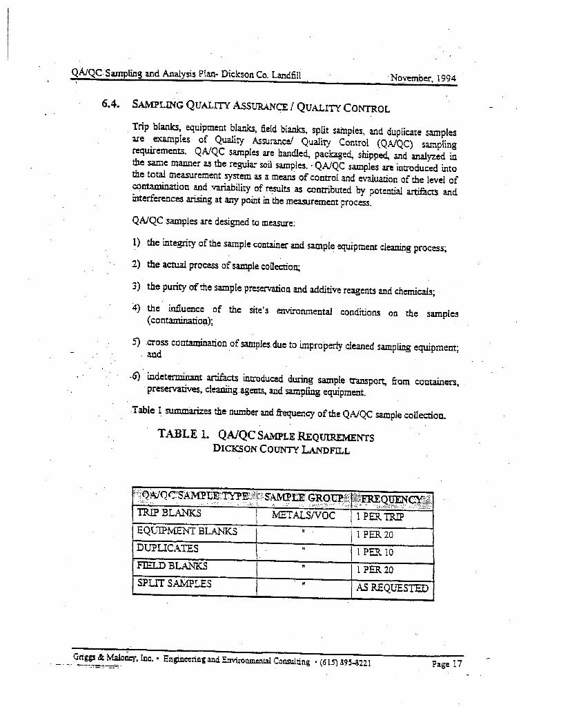
QAIQC. Sampling and Analysis P!an- Dickson Co, Landfill November, 1994
6.4. SAMPLING QUALITY AsSURANCE I QUALITY CONTROL
Trip blanks~ equipment blanks, field blanks, split samples, and duplicate samples are examples of Quality .Assurance/ Quality Control (QNQC) sampling requirements. QNQC samples are handled, packaged, ·shipped, and analyzed in the same manner as the regular soil samples. · QAJQC samples are introduced into the total measurement system as a means of control and evaluation of the level of contamination and variability of results as contributed by potential artifacts and interferences arising at any point in the measurement process.
QAJQC ·samples are designed to measure:
1) the integrity of the sample container and sample equipment cleaning process;
2) the actual process of sample collection;
3) the purity of the sample preservation and additive reagents and chemicals; ·
4) the influence of the site's environmental conditions on the samples ( contaminatio!l);
5) cross contamination of samples. due to improperly cleaned sampling equipment; . and · ·
.6) indeterminant artifacts introduced during sample transport, from containers, · preservatives, cleaning .agents, and samt'ling equipment.
Table 1 summarizes the number and frequency of the QAJQC sample colleCtion.
TABLE 1. QA/QC SAMPLE REQUIREMENTS DICKSON COUNTY LANDFILL
::i{~:~QC'SA~~LT'fl»E.;::;t:Ft~~u;.~~9Wj'1f: .f~~g~~&.t. TRIP BLA.J.'IT<S .METALSNOC I 1 PER TRIP EQv1P~1 BLANKS 1 PER20
DlJPUCATES I. 1 PER 10 . FIELD BLANKS " 1 PER20 SPLIT SAMPLES AS REQUESTED
Griggs&: Maloney, Inc. • Engineering and. Environmental Consulting • (615) 39~-3221 Page 17

QA/QC S~pling arid Analysis Plan- Dickson Co. Landfill November, 1994
·-
6.4.1. FIELD BLANKS
Field blanks are utilized to evaluate the sample container filling procedure, the. effects of environmental contaminants at the site, purity of preservatives or additives. ··
Field blanks are prepared in the field, on-site, by filling appropnate sample containers with DI water and adding appropriate preservatives and additives as required: The field blank sample is then grouped, handled, stored. and transported with the true samples collected at the site.
Fteld blanks will be collected at the rate of one (1) sample for each twenty (20) sampfes collected.
6.4.2. .TRJP BLANKS
Trip Blanks are prepared in the laboratory with laboratory grade (distilled or deionized) water. The water is placed into the sample containers to verify their cleanliness before and during the sampling project and, in the case of volatile· organics, will monitor the contamination of outside contamination on sample containers and coUected samples during transportation and storage.
One trip blank per sample set is to be prepared for each parameter group sampled.
6.4.3. EQUIPMENT BLANKS
· Equipment blanks, also known as rinseate blanks, are utilized to monitor the contamination or cross contamination of sampling equipment in the field from deficient field cleaning procedures: The equipment blank also addresses the field preservation procedures, environmental site interference. integrity of the source blank for field cleaning operations, and those concerns singularly addressed by the travel blank.
Samples of distilled or deioc.i:zed water are taken using a blank water rinse of the particuiar item or' samp1e equtpmem:: Tne equipme:~.t blank is used for sampling equipment li:.<:e bailers, pumps, pu.mp tubing, spoons, trowels, hand augers, or corers. The equipment blank is prepared by collection of DI water which is being poured over the sampling equipment during the final rinse. Appropriate pr·eservatives and additives which are required to be added to regular samples, will be added to the equipment blank in like manner.
One equipment blank sample per twenty (20) samples collected will be prepared.
Griggs&. Maloney, Inc. • Engineering and EnvironmentaL Consulting • (615) 895-3221 Page 18. ·. -

QA/QC Sampling and Analysis Plan- Dickson Co. Landfill November, 1994
6.4.4. DUPLICA.TE SAMPLES
Duplicate samples are utilized to monitor the reproducability of the sampling procedures and to provide the laboratory with sufficient sample to perform laboratory matrix spike and duplicate sample analysis. Dpplicate samples are .essentially identical samples. They are collected, preserved. handled, shipped, stored. and analyzed in the same manner as the regular samples. ·
One duplicate sample will be collected for each sample set of ten (10) samples collected for submittal to the laboratory.
Split samples are duplicate samples split between two or more parties for separate analysis.by unrelated laboratories.
7. CLEAl~G AND DECONTAMINATION OF SAM:PLING EQUIPl\1ENT
·-
7.1. S&\1PLE CONTAlNERS
Sample containers may be either purchased precfeaned or may be cleaned by the laboratory or fieid team. The 40 m1 YO A vials and containers to be used for samples for the pH, temperatUre, and specific conductivity measurements ·will · precleaned or will be cleaned by the following procedure prior to use.
A. V13ls, jars, caps, and lids will be washed with phosphate free detergent and hot water.
B. Rinse thoroughly with hot tap water.
C. Rinse with a solution of 10% nitric acid (CAUTION!!).
D. Rinse with tap water followed with DI water.
E Rinse twice with isopropyl (or methyl) alcohoL and allow to air dry for 24 hours.
F. Wrap with aluminum foil to prevent contamination during storage and transport to the site.
G. All alcohol and acid used for the decontamination process will be collected and disposed of properly whether generated in the laboratory or in the field.
7 .2. SAMPLING EQUIPMEN1'
All sampling equipment used at the site will be disposable polyethylene bailers and "Will not require additional cleaning.
Griggs & MalOn~. Inc. • Engineering and Environmental Consulting • (615) S95-3ll1 Pa~ 19
QA/QC Sampling and Analysis P!an- Dickson Co. Landfill November. 1994
4) Dibenzofuransl dibenzo-p-<iiox:ins
5) Mercwy
6) Total Metals
7) Cyanide
8) Sulfide
9) pH and Conductivity
11. DISPOSAL OF CONTAMINATED MATERIALS
All equipment, supplies, and waste which may contain or be contaminated with b.azirdous materials must be contained and handled for proper disposal. The foUowing are ecunples ·of poSSible contaminated materials:
A) Wat.er used for wasbing, rinsing, or decomamjnaring of sampling . equipment or supplies. · ·
B) Wat.er purged from weUs or excess samples.
C) Alcohols and acids. from sample container decootamina:tion..
D) Disposable and heavy work gloves.
E) DiSposable bailers and biiller support lines.
F) Pump and suction tubing~
G) Plastic sheeting used. for ground cover or work surfaces.
' 11.1. DIS:POSAL OF CONTAMINATED WATERS
Water from the decontamination. purging and sampling activities must be coUected in pails, drums or tanks for proper disposal. After completion of the sample analysis, if the samples contain contaminates at levels which may cause the wash waters to be deemed hazardous, the collected waters will be sampled and analyzed · to d.etermir.e "t.'-::. ~:·:.:t :.£ :~c':-::ryir,arion and the proper· disposal methodology fullowing rules and regulations in force at the time of disposal.
11.2. DISPOSAL OF SOL VENTS AND ACIDS
Solvents used in the lab and the field for decontamination of sample equipment, supplies, and contain~rs will be disposed of by:
Small quantities of solvents used to rinse cleaned containers and equipment and aot believed to have significant levels of contamination will. be disposed of by placing in a vented area and· allowed to eVaporate. Large quantities (> 1 liter) of
Griggs & .Maloney, Inc. • Engineering and Environmental Consulting • (615) 89S-3221 Page 23
QA/QC Sampling and Analysis Plan- Dickson Co. Landfill November, ~1994
waste solvents will be collected for disposal following rules and regulations in force at the time of disposal.
Solvents used to rins~ contaminated equipment which are believed to have significant levels of contamination will be disposed of by placing in an approved shipping container; sampled and analyzed to .determine if· it. is a hazardous waste~ and if determined to be ha:z:ardous, disposed of by proper disposal methods following rules and regulations in force at the time ofdisposal.
Nitric acid utilized for rinsing sampling equipment, containers, and supplies in the laboratory wi.11 be collected and disposed ofby neutralizing with sodium hydroxide and discharging into the publicly owned treatment works serving the laboratory. Nitric acid utilized in the field will be collected and returned to the laboratory for proper disposaL
11.3. DISPOSAL OF SOLID WASTE
All solid waste· including pl.astic sheeting. bailers, bailer support line, pump and suction tubing, gloves, and trash will be collected and screened with the HNU PID for indications ofvolatile orgamcs. If the HNU does not indicate volatile organics above the detectable level the waste will be dumped into the site's solid waste containers. If volatile organics are detected the waste will be sampled and ai13lyzed to determine if it is a hazardous waste, and if determined to be hazardous, · . ·· disposed of by proper disposal methods following rules and regulations in force at the time of disposaL
Griggs&: Maloaq, Inc. • Engineering and Environmental Consulting • (615) 895-8221 Page 24
APPENDIXB
EXA1\1PLE ·SAMPLE LABEL and SEAL
.· -:-. -· - ·~:--':"·.-:::---··~-::""""':":·-· ~--"'!.-: -··-:-:·- _-:-;- .• :"; .·-- ~- -··-. ····: •. ---- ;"" -- :-·: .. - .. -·· ·.-· • ---- - - -
APPENDIXC
CHAIN- OF- CUSTODY
-·-
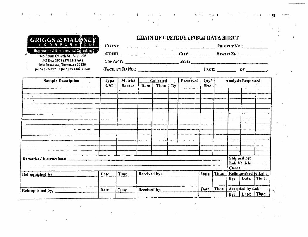
. GRIGGS & IVIAL
I r·l C 0 R P 0 R A · • ----========= Enn,neenno & Er,'J rnnmental CQJ1SlJilino ;
::..
74.S.South Cluucla St., Sui!c 205 PO Box 29611 (l71JJ-296U)
Murfreesboro, Tennessee l71JO (615) 895-8221 • (61 5) 895-0012 fAX
Sample Description
Remark1/ Instructions:
Relinquished hy:
Relinquished by:
-·
...
l ._~ ·J -, ~---! -.,- q --•
CHAIN OF CUSTODY I FIELD DATA SHEET
. CUEI'ff: PROJECT No.: ----STREET: CITY STATE/ZfP: _· ____ _
CON'fACT: SITE;----------------
FACILITY ID No.: -----------,.-- PAGE: OF ----Type Mntri:x/ Collected Preserved Qty/ Analysis Requested G/C Source Date Time By Size .
Shipped by: Lab Vehicle Client ·
Date Time Received by: Date Time Relin( ulshed to Lnh: By: Date: I Time:
Dnle Time Received by: Date Time Accepted by Lnh:
1--Dy: Date: I Time: