GRIPLINK-PLUG-IN FOR YASKAWA MOTOMAN
26
GRIPLINK-PLUG-IN FOR YASKAWA MOTOMAN Version 2.1.0
Transcript of GRIPLINK-PLUG-IN FOR YASKAWA MOTOMAN

GRIPLINK-PLUG-IN
FOR YASKAWA MOTOMAN Version 2.1.0
- 1 -
Content
1 Introduction ........................................................................................................................ 2
1.1 Notation and symbols ......................................................................................................... 2
1.2 Intended use ....................................................................................................................... 2
1.3 System requirements .......................................................................................................... 2
1.4 License terms ...................................................................................................................... 3
2 Installing the GRIPLINK plug-in ........................................................................................... 4
2.1 User variables ..................................................................................................................... 5
2.2 Behavior in case of error ..................................................................................................... 6
3 Command Reference .......................................................................................................... 7
3.1 Establish connection - CONNECT ........................................................................................ 8
3.2 Assert device type – DEVICE_ASSERT ................................................................................. 9
3.3 Activate device - ENABLE .................................................................................................. 10
3.4 Query device state - GET STATE ........................................................................................ 11
3.5 Deactivate device - DISABLE ............................................................................................. 12
3.6 Reference gripping module - HOME ................................................................................. 13
3.7 Grip a workpiece - GRIP .................................................................................................... 14
3.8 Simultaneous gripping of workpieces - MGRIP................................................................. 15
3.9 Release workpiece - RELEASE ........................................................................................... 16
3.10 Simultaneous release of workpieces - MRELEASE ............................................................ 17
3.11 Control mechanical force retention - CLAMP ................................................................... 18
3.12 Control of the LED display - LED........................................................................................ 19
3.13 Query of position and sensor values - VALUE ................................................................... 20
3.14 Configure grip preset – SET_GRIPCFG .............................................................................. 21
Device state....................................................................................................................... 23
Troubleshooting ................................................................................................................ 24

- 2 -
1 Introduction
With GRIPLINK technology, IO-Link compatible automation components can be connected to robot
systems from leading manufacturers using a standard network connection. The GRIPLINK plug-in for
YASKAWA Motoman is the control-side link and enables the simple integration of GRIPLINK technology
from WEISS ROBOTICS into robot systems from the manufacturer YASKAWA.
These instructions describe the functions of the GRIPLINK plug-in. For information on
mounting, commissioning and operation of the GRIPLINK controller, refer to the
operating instructions of the respective module. These can be found online at
www.griplink.de/manuals
1.1 Notation and symbols
For a better overview, the following symbols are used in these instructions:
Function or safety-relevant note. Non-observance may endanger the safety of personnel and plant, damage the device or impair the function of the device.
Additional information for a better understanding of the described facts.
Reference to further information.
1.2 Intended use
The "GRIPLINK Plug-in" software is intended for communication between the GRIPLINK Controller from
WEISS ROBOTICS and a robot controller. The requirements of the applicable directives and the
installation and operating instructions in these instructions must be observed and complied with. Any
other use or use beyond the scope of this manual is considered improper use. The manufacturer is not
liable for any damage resulting from this.
1.3 System requirements
This plug-in is compatible with GRIPLINK from firmware version 2.0.0.
One of the following YASKAWA robot controllers is required for operation:
• DX 100
• DX 200
• YRC 1000
The following robot options are required to run the software:

- 3 -
• MotoPlus software option.
Contact your YASKAWA distributor to obtain robot options.
The IP address of the GRIPLINK controller must be in the same subnet as that of the
robot controller. The GRIPLINK controller manual describes the exact procedure for
changing the IP address.
1.4 License terms
The GRIPLINK plug-in is protected by copyright. The respective valid license terms are included in the
software package. With the installation you accept these license terms.

- 4 -
2 Installing the GRIPLINK plug-in
To operate the GRIPLINK-ET4, the GRIPLINK plug-in is required on the robot controller. To install the
GRIPLINK plug-in, follow points 1 to 4.
2.1 Installation on classic teach pendant
Make sure that you are using the latest version of the GRIPLINK plug-in. The current version can be downloaded from www.griplink.de/plug-ins.
1. Unpack the previously downloaded ZIP archive with the GRIPLINK plug-in into the root
directory of a USB drive and insert it into the USB slot of the teach pendant.
2. Copy the GRIPLINK plug-in (MotoPlus daemon) "griplink_xxxx.out" from the USB stick to
the robot controller, where xxxx stands for the controller used:
o Start the control in maintenance mode by pressing and holding the MENU
key on the teach pendant when switching on.
o Switch to the management mode. To do this, select the "SECURITY" option
in the "Main Menu" under "SYSTEM" and select the "MANAGEMENT MODE"
with the SELECT key.
o Enter the password. The default password is 16 times the nine
(9999999999999999)
o Load the GRIPLINK plug-in software package in the Main Menu under
"MotoPlus APL." at the option "LOAD (USER APPLICATION)" with the Select
button.
NOTE: The GRIPLINK plug-in must not be located in a subfolder.
3. Restart the controller.
4. Copy the GRIPLINK jobs from the USB stick to the robot controller.
2.2 Installation on Smart Pendant
To install the GRIPLINK plug-in on the Yaskawa Smart Pendant, copy the appropriate package file with
extension .yip (griplink_yrc1000.yip or griplink_yrc1000m.yip, according to the type of controller that
comes with your robot system) into the root directory of a USB drive. Then insert the USB drive into
the USB slot of the Smart Pendant.
The package contains all the necessary files (ie. job files and MotoPlus daemon). Install it by selecting
“System Settings” -> “Packages” from the menu. Then choose the previously copied .yip file on the USB
drive.
During installation, the controller will have to be restarted.

- 5 -
2.3 User variables
The GRIPLINK plug-in uses a block of 13 user variables of type "double" for communication between
GRIPLINK plug-in and robot program. The variable block is stored from address 87 by default. The
purpose of each variable is listed in the following table.
Address offset Content
0 Return value (RETVAL0) of the called function
1 Return value (RETVAL1) of the called function
2 Return value (RETVAL2) of the called function
3 Return value (RETVAL3) of the called function
4 Diagnostic counter
5
Reserved for communication with the GRIPLINK plug-in software package
6
7
8
9
10
11
12
The variables 0 to 3 return the return values of the executed command.
With variable 4 a diagnostic counter is realized, which is periodically incremented by the GRIPLINK
plug-in and gives information about its state.
Variables 5 to 12 are reserved for internal communication between the library commands and the
GRIPLINK plug-in and must not be changed.
Change range of user variables
Depending on the robot program, it may be necessary to move the memory area used by the GRIPLINK
plug-in. To do this, proceed as follows:
1. Select the "JOB" field in the Main Menu and then the "SELECT JOB" field.
2. Now select the job "GRIPLINK_EXECUTE_CMD" in the "JOB LIST" and confirm your selection
with the SELECT button.
3. Set the start address of the variable block (default value is 87).
4. Restart the robot controller (the GRIPLINK plug-in will apply the changes on restart).

- 6 -
2.4 Behavior in case of error
If an error occurs within the GRIPLINK plug-in or during communication with the GRIPLINK controller,
the running robot program is basically stopped by means of an error. This usually leads to the fact that
running movements of the robot are aborted. The same applies if the addressed device is in FAULT
state or changes to this state due to a command.
- 7 -
3 Command Reference
The GRIPLINK plug-in provides the user with a collection of generic motion and gripping functions as
well as functions for reading connected sensors. The commands are realized as robot jobs, which
receive their parameters as transfer values and communicate with a MotoPlus program in the
background via a common register area. The return values of the commands are stored in the user
variables (see section 2.3). To execute a command, the corresponding robot job must be called. Some
jobs are available as single as well as multiple commands.
The basic program flow with the GRIPLINK plug-in is always as follows:
1. Establish connection with GRIPLINK_CONNECT
2. Activate gripping module or sensor with GRIPLINK_ENABLE
3. For servo gripping modules without absolute encoder: Reference gripping module with
GRIPLINK_HOME
4. Grasp/release with GRIPLINK_GRIP or GRIPLINK_RELEASE
5. Query position or measured value with GRIPLINK_VALUE
The available commands of the GRIPLINK plug-in are described below.

- 8 -
3.1 Establish connection - CONNECT
This command establishes the connection between the GRIPLINK controller and the robot controller.
The IP address of the GRIPLINK controller is passed as the transfer parameter. The command waits
until the connection is established. If the GRIPLINK controller cannot be reached at the specified
address, a user alarm is triggered and program execution is stopped.
If GRIPLINK-ET4 commands are executed before a GRIPLINK_CONNECT, this will trigger a User Alarm.
The IP address of the GRIPLINK controller can be changed via the GRIPLINK-ET4 website.
Syntax
CALL GRIPLINK_CONNECT(< IPADDR. 0 > , < IPADDR. 1 > , < IPADDR. 2 > , < IPADDR. 3 > , < RES > )
Parameters
< IPADDR. 0 > First byte of the IP address
< IPADDR. 1 > Second byte of the IP address
< IPADDR.2 > Third byte of the IP address
< IPADDR.3 > Fourth byte of the IP address
< Res > Reserved, set to 0
Return values
RETVAL 0 to 3 not used (0)
Example
Establish connection between robot and the GRIPLINK with IP address 192.168.1.40:
CALL GRIPLINK_CONNECT(192,168,1,40,0)

- 9 -
3.2 Assert device type – DEVICE_ASSERT
Checks whether the device connected to the specified device port has the specified type. If this is not
the case, the function triggers a user alarm and the program execution is aborted.
Syntax
CALL GRIPLINK_DEVICE_ASSERT(< PORT >, < VENDOR_ID >, < DEVICE_ID >)
Parameters
< PORT > Index of the device port (0 to 3)
< VENDOR_ID > Expected Vendor ID number. This is assigned to the manufacturer by the IO-
Link Association.
< DEVICE_ID > Expected Device ID number. Identification number of the device assigned
by the device manufacturer.
Return values
RETVAL 0 to 3 not used (0)
Example
Make sure that a gripping module of type IEG 55-020 (Device ID: 20) from Weiss Robotics (Vendor
ID: 815) is connected to port 0:
CALL GRIPLINK_DEVICE_ASSERT(0,815,20)

- 10 -
3.3 Activate device - ENABLE
This command activates the device connected to the specified device port.
GRIPLINK_ENABLE must be executed after GRIPLINK_CONNECT for all devices.
If GRIPLINK commands are executed before a GRIPLINK_ENABLE, this will trigger a User Alarm.
Syntax
CALL GRIPLINK_ENABLE(< PORT >)
Parameters
< PORT > Index of the device port (0 to 3)
Return values
RETVAL 0 actual device state (see Appendix A)
RETVAL 1 to 3 not used (0)
Example
Activate drive and gripping module at port 0:
CALL GRIPLINK_ENABLE(0)

- 11 -
3.4 Query device state - GET STATE
This command returns the state of the selected device.
Syntax
CALL GRIPLINK_GET_STATE(< PORT >)
Parameters
< PORT > Index of the device port (0 to 3)
Return values
RETVAL 0 actual device state (see Appendix A)
RETVAL 1 to 3 not used (0)
Example
Wait until the device state of the gripping module at port 2 is "HOLDING" (4):
*WAIT
TIMER T=0.01
CALL GRIPLINK_GET_STATE(2)
IF(D087<>4) THEN
JUMP *WAIT
ENDIF
- 12 -
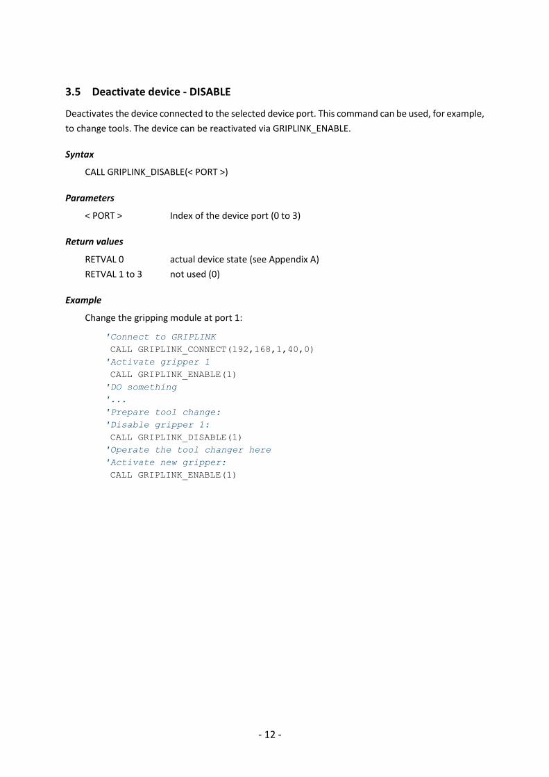
3.5 Deactivate device - DISABLE
Deactivates the device connected to the selected device port. This command can be used, for example,
to change tools. The device can be reactivated via GRIPLINK_ENABLE.
Syntax
CALL GRIPLINK_DISABLE(< PORT >)
Parameters
< PORT > Index of the device port (0 to 3)
Return values
RETVAL 0 actual device state (see Appendix A)
RETVAL 1 to 3 not used (0)
Example
Change the gripping module at port 1:
'Connect to GRIPLINK
CALL GRIPLINK_CONNECT(192,168,1,40,0)
'Activate gripper 1
CALL GRIPLINK_ENABLE(1)
'DO something
'...
'Prepare tool change:
'Disable gripper 1:
CALL GRIPLINK_DISABLE(1)
'Operate the tool changer here
'Activate new gripper:
CALL GRIPLINK_ENABLE(1)

- 13 -
3.6 Reference gripping module - HOME
References the selected servo gripper. The command executes a reference run of the gripping module
and waits until this is completed. After the GRIPLINK_HOME command has been executed, the fingers
of the gripping module are powerless and must be moved to a defined position with a
GRIPLINK_GRIP/MGRIP or GRIPLINK_RELEASE/MRELEASE.
The reference run can be configured via the web interface of the GRIPLINK controller.
Syntax
CALL GRIPLINK_HOME(< PORT >)
Parameters
< PORT > Index of the device port (0 to 3)
Return values
RETVAL 0 actual device state (see Appendix A)
RETVAL 1 to 3 not used (0)
Example
Reference the gripping module to port 2:
CALL GRIPLINK_HOME(2)

- 14 -
3.7 Grip a workpiece - GRIP
Grips a workpiece with the selected gripping module and the selected handle. The command waits
until the device state changes to either "HOLDING" or "NO PART".
The gripping parameters can be configured via the web interface of the GRIPLINK interface converter.
Syntax
CALL GRIPLINK_GRIP(< PORT >, < PRESET >)
Parameters
< PORT > Index of the device port (0 to 3)
< PRESET > Selected handle (range depends on selected gripper model)
Return values
RETVAL 0 actual device state (see Appendix A)
RETVAL 1 to 3 not used (0)
Examples
Gripping module at port 0 is to grip with grip 2. If no workpiece was found, the gripper should
open again and try again:
*LOOP
CALL GRIPLINK_GRIP(0,2)
IF(D087<>5) THEN'No
part, open and try again:
CALL GRIPLINK_RELEASE(0,2) JUMP *LOOP
ENDIF
'Part gripped!

- 15 -
3.8 Simultaneous gripping of workpieces - MGRIP
This command executes a grip with the selected gripping modules. The command waits until all
gripping modules have each reached one of the states "HOLDING" or "NO PART".
The gripping parameters can be configured via the web interface of the GRIPLINK interface converter.
Syntax
CALL GRIPLINK_MGRIP(< PORTS >, < PRESET >)
Parameters
< PORTS > Selected gripping modules as bit vector:
Bit 0: 1 = gripping module selected at port 0, 0 = not selected
Bit 1: 1 = gripping module selected at port 1, 0 = not selected
Bit 2: 1 = gripping module selected at port 2, 0 = not selected
Bit 3: 1 = gripping module selected at port 3, 0 = not selected
Bit 31...4: reserved (set to 0)
< PRESET > Selected grip recipe (range depends on selected gripper model).
Return values
RETVAL 0 actual device state of gripping module at port 0 (see Appendix A)
RETVAL 1 actual device status of gripping module at port 1 (see Appendix A)
RETVAL 2 actual device status of gripping module at port 2 (see Appendix A)
RETVAL 3 actual device status of gripping module at port 3 (see Appendix A)
Examples
Gripping modules at port 1 and 2 (0110 binary => 6 decimal) grip workpiece with grip recipe 2:
CALL GRIPLINK_MGRIP(6,2)

- 16 -
3.9 Release workpiece - RELEASE
Releases the workpiece gripped with the selected gripping module. The command waits until the
workpiece has been released.
The gripping parameters can be configured via the web interface of the GRIPLINK interface converter.
Syntax
CALL GRIPLINK_RELEASE(< PORT >, < PRESET >)
Parameters
< PORT > Index of the device port (0 to 3)
< PRESET > Selected grip recipe (range depends on selected gripper model).
Return values
RETVAL 0 actual device state (see Appendix A)
RETVAL 1 to 3 not used (0)
Examples
Release the workpiece gripped with the gripping module at port 0 and grip recipe 2:
CALL GRIPLINK_RELEASE(0,2)

- 17 -
3.10 Simultaneous release of workpieces - MRELEASE
Simultaneously releases the workpiece gripped with the selected gripping modules. The command
waits until all gripping modules have each reached the "RELEASED" state.
Syntax
CALL GRIPLINK_MRELEASE(< PORTS >, < PRESET >)
Parameters
< PORTS > Selected gripping modules as bit vector:
Bit 0: 1 = gripping module selected at port 0, 0 = not selected
Bit 1: 1 = gripping module selected at port 1, 0 = not selected
Bit 2: 1 = gripping module selected at port 2, 0 = not selected
Bit 3: 1 = gripping module selected at port 3, 0 = not selected
Bit 31...4: reserved (set to 0)
< PRESET > Selected grip recipe (range depends on selected gripper model).
Return values
RETVAL 0 actual device state of gripping module at port 0 (see Appendix A)
RETVAL 1 actual device state of the gripping module at port 1 (see Appendix A)
RETVAL 2 actual device state of the gripping module at port 2 (see Appendix A)
RETVAL 3 actual device state of the gripping module at port 3 (see Appendix A)
Examples
Gripping module at port 1,2 and 3 (1110 binary => 14 decimal) release their
workpiece with grip recipe 3:
CALL GRIPLINK_MRELEASE(14,3)
- 18 -
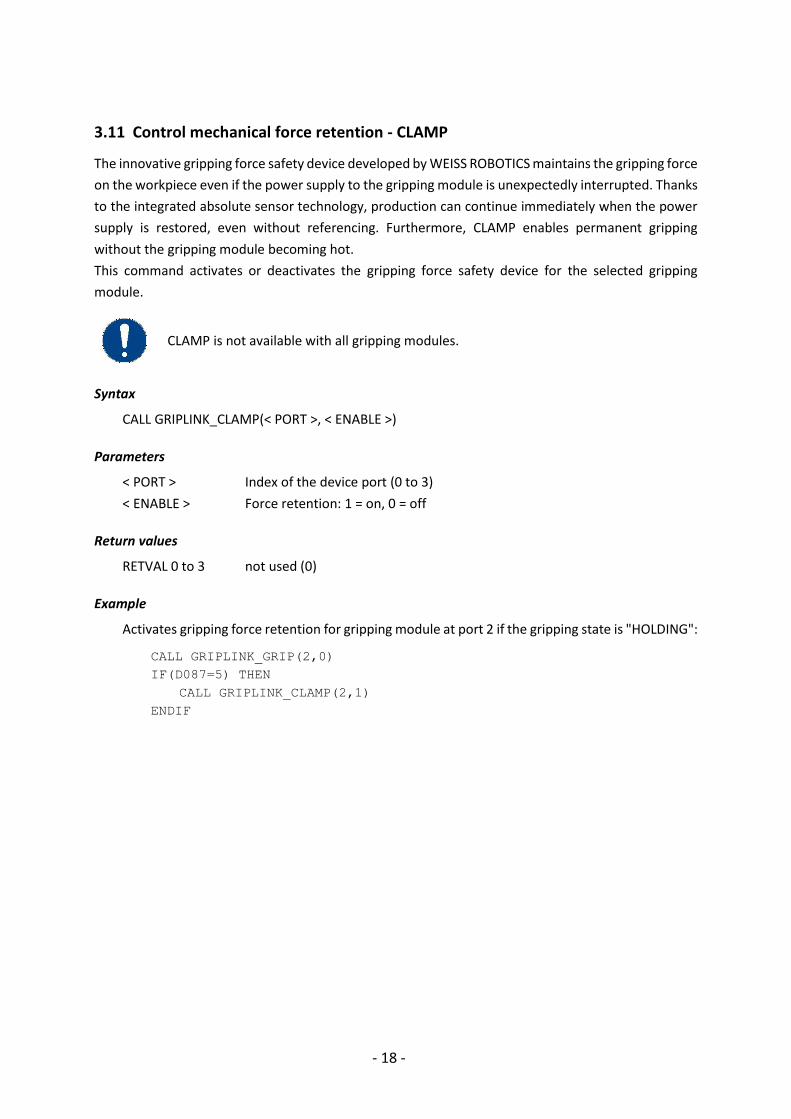
3.11 Control mechanical force retention - CLAMP
The innovative gripping force safety device developed by WEISS ROBOTICS maintains the gripping force
on the workpiece even if the power supply to the gripping module is unexpectedly interrupted. Thanks
to the integrated absolute sensor technology, production can continue immediately when the power
supply is restored, even without referencing. Furthermore, CLAMP enables permanent gripping
without the gripping module becoming hot.
This command activates or deactivates the gripping force safety device for the selected gripping
module.
CLAMP is not available with all gripping modules.
Syntax
CALL GRIPLINK_CLAMP(< PORT >, < ENABLE >)
Parameters
< PORT > Index of the device port (0 to 3)
< ENABLE > Force retention: 1 = on, 0 = off
Return values
RETVAL 0 to 3 not used (0)
Example
Activates gripping force retention for gripping module at port 2 if the gripping state is "HOLDING":
CALL GRIPLINK_GRIP(2,0)
IF(D087=5) THEN
CALL GRIPLINK_CLAMP(2,1)
ENDIF
- 19 -
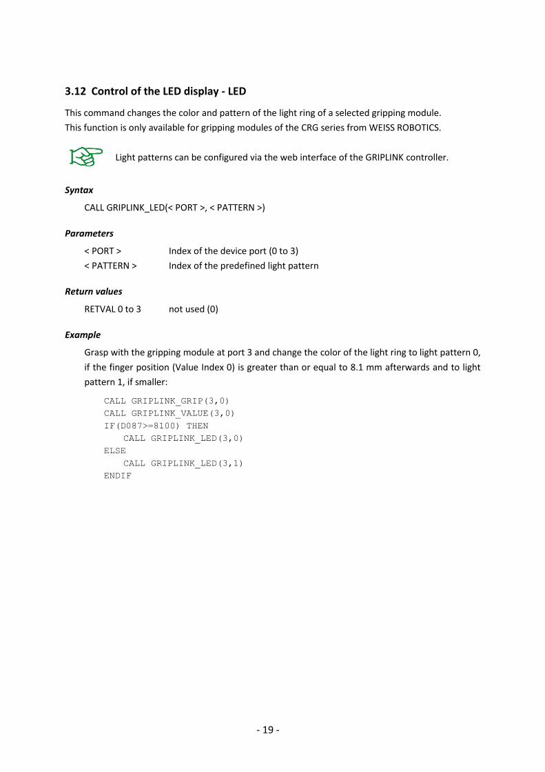
3.12 Control of the LED display - LED
This command changes the color and pattern of the light ring of a selected gripping module.
This function is only available for gripping modules of the CRG series from WEISS ROBOTICS.
Light patterns can be configured via the web interface of the GRIPLINK controller.
Syntax
CALL GRIPLINK_LED(< PORT >, < PATTERN >)
Parameters
< PORT > Index of the device port (0 to 3)
< PATTERN > Index of the predefined light pattern
Return values
RETVAL 0 to 3 not used (0)
Example
Grasp with the gripping module at port 3 and change the color of the light ring to light pattern 0,
if the finger position (Value Index 0) is greater than or equal to 8.1 mm afterwards and to light
pattern 1, if smaller:
CALL GRIPLINK_GRIP(3,0)
CALL GRIPLINK_VALUE(3,0)
IF(D087>=8100) THEN
CALL GRIPLINK_LED(3,0)
ELSE
CALL GRIPLINK_LED(3,1)
ENDIF

- 20 -
3.13 Query of position and sensor values - VALUE
Reads a measured value from the connected device. Depending on the device, one or more measured
values are available, which can be selected via the index to be specified.
For gripping modules and similar actuators, index 0 always corresponds to the finger position/gripping distance in micrometers.
Syntax
CALL GRIPLINK_VALUE(< PORT >, < INDEX >)
Parameters
< PORT > Index of the device port (0 to 3)
< INDEX > Index of the measured value to be queried
Return values
RETVAL 0 returns the measured value
Example 1
Query the distance to the workpiece (measured value index 0) of the laser distance sensor
connected to port 1 and grip with the gripper at port 3 if the distance is smaller than 42 mm.
Otherwise, call the "SKIP" sub program:
CALL GRIPLINK_VALUE(1,0)
IF(D087<42000) THEN
CALL GRIPLINK_GRIP(3,0)
ELSE
CALL SKIP
ENDIF
Example 2
Execute the subroutine "PROG" if the finger position of the gripping module at port 2 is greater
than 10.5 mm:
CALL GRIPLINK_VALUE(2,0)
IF(D087>10500) THEN
CALL PROG
ENDIF

- 21 -
3.14 Configure grip preset – SET_GRIPCFG
Parameterizes a gripping recipe directly from the robot program. GRIPLINK does not save these
settings permanently, they are lost when switched off. This command is intended to link specific tool
settings to the robot program, ensuring that the tool settings match the program.
Due to limitations of the robot, only the first 5 of the 8 gripping parameters can be configured. The remaining parameters 6 to 8 are initialized to 0. Check whether your device requires more than 5 gripping parameters.
Use the setting options via the GRIPLINK web interface to fully parameterize and permanently save gripping recipes.
Syntax
CALL GRIPLINK_SET_GRIPCFG(< PORT >, < GRIP_INDEX >, < PARAM0 >, …, < PARAM4 >)
Parameters
< PORT > Index of the device port (0 to 3)
< GRIP_INDEX > Grip index. Number of available presets depends on the device type.
< PARAM0…4 > Device-specific grip parameters 0 to 4. The parameters correspond to the
first five gripping parameters that can be set via the web interface,
multiplied by a factor of 1000.
The following assignment applies to gripping modules from Weiss Robotics:
• PARAM0: No-Part Position/Threshold in Micrometers
• PARAM1: Release Position/Threshold in Micrometers
• PARAM2: Gripping force in Percent x 1000 (only valid on servo
grippers)
• PARAM3…4: unused, set to 0
Return values
RETVAL 0 to 3 unused (0)
Example 1
Configure the Weiss Robotics IEG 55-020 gripper at port 0 with the following settings:
• No-Part Position: 3 mm
• Release Position: 10 mm
• Gripping force: 100%
CALL GRIPLINK_SET_GRIPCFG(0,3000,10000,100000,0,0)
Example 2
Configure the PIAB vacuum pump piCOMPACT 23 at port 1 with the following settings:

- 22 -
• Vacuum setpoint: 40 kPa
• Energy saving setpoint: 75 kPa
• Blow-off duration: 300 Milliseconds
CALL GRIPLINK_SET_GRIPCFG(1,40000,75000,300000,0,0)

- 23 -
Device state
Device status Code Description
NOT CONNECTED 0 No device connected
NOT INITIALIZED 1 Not initialized
DISABLED 2 Ready for operation, but not activated
RELEASED 3 Workpiece released
NO PART 4 No workpiece found
HOLDING 5 Workpiece is held
OPERATING 6 Ready for operation
FAULT 7 Error condition

- 24 -
Troubleshooting
Error message "GRIPLINK TIMED OUT".
• The GRIPLINK daemon has been terminated.
• Restart robot and GRIPLINK controller and try again.
Error message "GRIPLINK BUSY".
• Check the setting for the registers used by GRIPLINK (chapter 2.1). Changes will be applied
when the robot is restarted.
• Make sure that the area is not overwritten by your robot program.
Error message "GRIPLINK INVALID BASE ADDR".
• The start address of the variable block configured in the GRIPLINK_EXECUTE_CMD job file is
not supported by the robot controller.
• Set a start address where the whole variable block used by GRIPLINK fits into the robot's
variable memory (chapter 2.1) and restart the robot. YRC 1000 controllers support up to 100
double variables, so the highest start address is 87.

.
© 2020 WEISS ROBOTICS GmbH & Co. KG. All rights reserved. GRIPLINK and PERMAGRIP are registered trademarks of WEISS ROBOTICS GmbH & Co. KG. All other trademarks are the property of their respective owners. Specifications given in this document are subject to change without notice for the purpose of product improvement. Trademarks are the property of their respective owners. Our products are not intended for use in life support systems or systems where failure could result in personal injury.


![MH24DX200 FS100 MLX200 CONTROLLERS MOTOMAN IS A REGISTERED TRADEMARK ALL OTHER MARKS ARE THE TRADEMARKS AND REGISTERED TRADEMARKS OF YASKAWA AMERICA, INC. Axes [ ] …](https://static.fdocuments.in/doc/165x107/61265aebd7843d05c938503c/dx200-fs100-mlx200-controllers-motoman-is-a-registered-trademark-all-other-marks.jpg)