Gridley Ethanol Demonstration Project Utilizing … 2005 • NREL/SR-510-37581 Gridley Ethanol...
36
February 2005 • NREL/SR-510-37581 TSS Consultants For the City of Gridley, California Gridley, California Gridley Ethanol Demonstration Project Utilizing Biomass Gasification Technology: Pilot Plant Gasifier and Syngas Conversion Testing August 2002—June 2004 National Renewable Energy Laboratory 1617 Cole Boulevard, Golden, Colorado 80401-3393 303-275-3000 • www.nrel.gov Operated for the U.S. Department of Energy Office of Energy Efficiency and Renewable Energy by Midwest Research Institute • Battelle Contract No. DE-AC36-99-GO10337
Transcript of Gridley Ethanol Demonstration Project Utilizing … 2005 • NREL/SR-510-37581 Gridley Ethanol...

February 2005 • NREL/SR-510-37581
TSS Consultants For the City of Gridley, California Gridley, California
Gridley Ethanol Demonstration Project Utilizing Biomass Gasification Technology: Pilot Plant Gasifier and Syngas Conversion Testing August 2002—June 2004
National Renewable Energy Laboratory 1617 Cole Boulevard, Golden, Colorado 80401-3393 303-275-3000 • www.nrel.gov
Operated for the U.S. Department of Energy Office of Energy Efficiency and Renewable Energy by Midwest Research Institute • Battelle
Contract No. DE-AC36-99-GO10337

February 2005 • NREL/SR-510-37581
Gridley Ethanol Demonstration Project Utilizing Biomass Gasification Technology: Pilot Plant Gasifier and Syngas Conversion Testing August 2002—June 2004 TSS Consultants For the City of Gridley, California Gridley, California
NREL Technical Monitor: M. Ruth Prepared under Subcontract No. ZCO-2-32065-01
National Renewable Energy Laboratory 1617 Cole Boulevard, Golden, Colorado 80401-3393 303-275-3000 • www.nrel.gov
Operated for the U.S. Department of Energy Office of Energy Efficiency and Renewable Energy by Midwest Research Institute • Battelle
Contract No. DE-AC36-99-GO10337

This publication was reproduced from the best available copy submitted by the subcontractor and received no editorial review at NREL
NOTICE This report was prepared as an account of work sponsored by an agency of the United States government. Neither the United States government nor any agency thereof, nor any of their employees, makes any warranty, express or implied, or assumes any legal liability or responsibility for the accuracy, completeness, or usefulness of any information, apparatus, product, or process disclosed, or represents that its use would not infringe privately owned rights. Reference herein to any specific commercial product, process, or service by trade name, trademark, manufacturer, or otherwise does not necessarily constitute or imply its endorsement, recommendation, or favoring by the United States government or any agency thereof. The views and opinions of authors expressed herein do not necessarily state or reflect those of the United States government or any agency thereof.
Available electronically at http://www.osti.gov/bridge
Available for a processing fee to U.S. Department of Energy and its contractors, in paper, from:
U.S. Department of Energy Office of Scientific and Technical Information P.O. Box 62 Oak Ridge, TN 37831-0062 phone: 865.576.8401 fax: 865.576.5728 email: mailto:[email protected]
Available for sale to the public, in paper, from: U.S. Department of Commerce National Technical Information Service 5285 Port Royal Road Springfield, VA 22161 phone: 800.553.6847 fax: 703.605.6900 email: [email protected] online ordering: http://www.ntis.gov/ordering.htm
Printed on paper containing at least 50% wastepaper, including 20% postconsumer waste

iii
TABLE OF CONTENTS I. PURPOSE OF THE REPORT......................................................................... 1
II. RELATED EVALUATION STUDIES........................................................ 1
III. BACKGROUND ................................................................................................ 1
A. RICE STRAW BURNING REDUCTION ACT OF 1991..................................................... 1 B. THE PROPOSED GRIDLEY ETHANOL DEMONSTRATION PROJECT............................... 2 C. GRIDLEY ETHANOL PROJECT OBJECTIVES ................................................................ 3 D. BIOMASS GASIFICATION BASICS ............................................................................... 3
IV. EXPERIMENTAL PLAN............................................................................... 4
V. DESCRIPTION OF THE PEARSON PILOT PLANT TECHNOLOGY........................................................................................................... 6
A. PILOT PLANT LOCATION ........................................................................................... 6 Figure V-1 Regional Map of Mississippi ................................................................. 7 Figure V-2 Local Map for Aberdeen, Mississippi and Location of Pearson Technologies Site ........................................................................................................ 7 Figure V-3 Aerial Photo of Pearson Technology Site (c. 1996).............................. 8 Figure V-4 Photo of Pearson Technology Site (May 2003) ..................................... 8
B. PEARSON TECHNOLOGY DESCRIPTION ...................................................................... 9 C. DETAILED PROCESS DESCRIPTION........................................................................... 10
Figure V-5. Pearson Technologies Process Flow Diagram................................... 11 D. FEEDSTOCK HANDLING SYSTEM ............................................................................. 12
Figure V-6. Feeder for the Verdyol Bale Breaker ................................................... 14 Figure V-7. Conveyor from the Bale Breaker to the Hammer Mill ......................... 14 Figure V-8. Schutte-Buffalo Hammer Mill at Verdyol Mulch of Canada................ 15
VI. ENERGY AND MASS BALANCE ANALYSES ................................. 16
A. RICE STRAW PROPERTIES........................................................................................ 16 B. SYNGAS ENERGY BALANCE ANALYSES .................................................................. 16
Table VI-1. Energy Content of Syngas Constituents................................................ 18 C. SYSTEM CARBON BALANCE ANALYSES (EXPERIMENTAL)...................................... 19 D. ETHANOL MASS BALANCE ANALYSES (EXPERIMENTAL)........................................ 19
Table VI-2. Physical Properties of Ethanol............................................................. 20 Figure VI-1. Determination of Ethanol Mass Balances (Experimental) ................ 21
E. ETHANOL MASS BALANCE ANALYSES (OPTIMIZED) ............................................... 21 Table VI-3. The Composition of Syngas That Would Result from the ..................... 22 Conversion of all CO2 to CO .................................................................................... 22 Figure VI-2. Determination of Ethanol Mass Balances (Optimized) ..................... 23
F. ETHANOL MASS BALANCE ANALYSES (THEORETICAL)........................................... 23
VII. CONCLUSIONS AND RECOMMENDATIONS .............................. 24
A. THE PILOT CONVERSION SYSTEM ........................................................................... 24

iv
B. FEEDSTOCK CHARACTERISTICS THAT HAVE A NEGATIVE IMPACT ON THE CATALYST....................................................................................................................................... 24 C. CATALYST PERFORMANCE ...................................................................................... 25 D. OTHER ISSUES: PEARSON FISCHER-TROPSCH PERFORMANCE IN CONVERTING SYNGAS TO ETHANOL .................................................................................................... 25 E. FEEDSTOCK HANDLING PROBLEMS ......................................................................... 25 F. CONDITIONS RECOMMENDED FOR THE PROPOSED DEMONSTRATION PLANT .......... 26 G. ENERGY AND MASS BALANCE ANALYSES .............................................................. 27
Table VII-1. Thermal Energy Efficiencies for the Conversion of Rice Straw to Various Products Using the Pearson Technologies System ..................................... 28
VIII. REFERENCES.............................................................................................. 30
1
GRIDLEY ETHANOL DEMONSTRATION PROJECT UTILIZING BIOMASS GASIFICATION TECHNOLOGY
PILOT PLANT GASIFIER AND SYNGAS
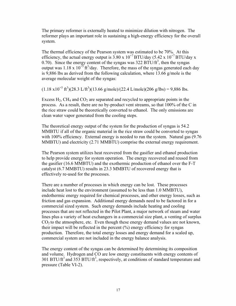
CONVERSION TESTING I. PURPOSE OF THE REPORT This report is in response to Task 3 of the National Renewable Energy Laboratory (NREL) Subcontract No. ZCO-2-32065-01, that describes the Pearson Technologies Pilot Plant Gasifier and Syngas Conversion Testing for converting California rice straw into syngas and then the syngas into ethanol. The report on this task of the NREL Subcontract is part of an overall evaluation of using a modified Pearson Pilot Plant for processing rice straw into syngas and ethanol and the application of the Pearson technology for building a Demonstration Plant at Gridley. The Demonstration Plant would be located in the recently developed City of Gridley Industrial Park in Gridley, California (“Gridley”). This report also includes information on the feedstock preparation, feedstock handling, feedstock performance, catalyst performance, ethanol yields and potential problems identified from the pilot scale experiments. II. RELATED EVALUATION STUDIES The evaluation of the Pearson technology, using rice straw for a proposed Demonstration Project at Gridley, is being conducted through this initial NREL subcontract that overlaps with a more comprehensive evaluation under a related Department of Energy (DOE) Subcontract that is developing a feasibility study using information from this pilot plant data. The DOE Study includes milestones and go/no-go decisions as to proceeding with the proposed Demonstration Plant using the Pearson technology at the Gridley site. III. BACKGROUND
A. Rice Straw Burning Reduction Act of 1991
Approximately 500,000 acres of rice are harvested annually in California, resulting in the availability of approximately 1 million bone dry tons (BDT) of rice straw annually. The Rice Straw Burning Reduction Act of 1991 (AB 1378) mandated a reduction in rice straw burning by the year 2000 to no more than 25% of the planted acreage. The California rice straw burning phase-down has proceeded as required by the statutes, with growers burning less than the statute limitations. Other open field burning laws and regulations further limit the actual rice straw acreage burned

2
annually. The total rice acreage burned annually has declined from 303,000 acres in 1992, the first year of the phase-down, to slightly less than 72,000 acres in 2002.
The State of California enacted legislation in 1997 (SB 318 -Rice Straw Demonstration Project), to modify existing law to provide a pause in the phase down of rice straw burning. This legislation was necessary because anticipated commercial technologies that could utilize significant amounts of rice straw had not yet developed. This legislation established a fund to provide cost-sharing grants for the development by demonstration projects for new rice straw technologies. Since its establishment in 1997, the California Air Resources Board (CARB) has awarded $5 million in funds to 10 recipients for demonstration and commercialization projects through the Rice Straw Demonstration Project Grant Fund.
The Gridley Ethanol Project, through the efforts of the Rice Straw Cooperative, was able to take advantage of the program and received $380,000 as a 50% cost sharing grant to collect, transport and store 18,000 BDT of rice straw for this project during 2000 and 2001. This grant allowed the Rice Straw Cooperative the opportunity to gain valuable experience in developing and operating a rice straw collection infrastructure.
These grants were intended to support diversion of 50% or more of rice straw produced toward off-field uses by 2000, the legislative goal. Off-field uses could include, but were not limited to, the production of energy and fuels, construction materials, pulp, paper, and livestock feed. New technologies had not yet been sufficiently developed to achieve this goal. CARB reports that only 3–5 % (approximately 18,000 tons) of the rice straw grown in California is currently used off-field. The primary uses to date have been for cattle feed and for erosion control.
B. The Proposed Gridley Ethanol Demonstration Project
Gridley is located in the heart of California’s rice growing area and its economy is uniquely dependent on rice production and markets. In addition, Gridley operates a municipal utility, with responsibility for delivering electrical power to the community. The Gridley community, including local rice growers, initiated the Gridley Ethanol Project to solve a major rice straw disposal problem and help maintain the economic viability in Butte County and the greater Sacramento Valley. The proposed Gridley Ethanol Project will utilize rice straw to produce ethanol for the transportation fuel markets.
A viable market alternative to the disposal of rice straw will reduce the alternative disposal costs of the phase-down of rice straw burning for rice growers. One of the more promising technologies for producing a high value product is to convert rice straw into ethanol. The current technology utilized by Pearson Technologies, Inc. (Pearson) has the theoretical potential to annually produce 20 million gallons of ethanol from 113,000 BDT of rice straw, co-host process heat and/or electricity.

3
In the fall of 1997, a group of Butte County rice growers, the Gridley Vice Mayor, Tom Sanford, and TSS Consultants (TSS) began to evaluate the feasibility of a rice straw-to-ethanol facility. During March 1998, the Butte County rice growers formed the Rice Straw Cooperative to provide supplies of rice straw to potential commercial users. The goal of this Cooperative was to find a reliable market for the rice straw in Butte County and to develop the infrastructure and methods to collect and transport the rice straw to a location where it can be economically converted to products. To date, members of the Cooperative have baled over 45,000 tons of rice straw over a six-year period to gain knowledge and evolve the infrastructure and techniques needed to collect and store rice straw.
The site for the proposed Gridley Ethanol Project is within the Gridley’s newly established Gridley Industrial Park. A 14.74 acre parcel located in the northeastern portion of the industrial park has been selected for the construction of this facility. Given the anticipated footprint of the ethanol production facility and associated infrastructure, it is estimated that approximately one month’s rice straw feedstock will be stored on this site. The supply plan envisions rice grower site storage at a few locations within the Butte County area.
C. Gridley Ethanol Project Objectives
The primary objectives of the Gridley Ethanol Project are to:
(a) Help preserve the Community’s agriculture economy in Butte County and adjacent areas.
(b) Support continued rice farming in the Sacramento Valley by providing a practical straw disposal alternative to burning.
(c) Create jobs, a new tax base and economic development in the Sacramento Valley. (d) Comply with the environmental legislative mandates to phase out most of the
open field rice straw burning. (e) Annually produce up to 20 million gallons of ethanol, a clean transportation fuel,
which can reduce tail-pipe emissions from California’s older in-use vehicles. D. Biomass Gasification Basics
A critical factor in the high-energy efficiency of the overall process is that of the gasifier (primary reformer). When any fuel is completely burned, all of its potential energy, or heating value (designated HP) in units of Btu/lb, is released as sensible (“can be felt”) heat (designated HS) that can be recovered for immediate use in a boiler, for example. In most established gasification processes, a fuel (wood or coal) is partially burned, leaving some gaseous products, while releasing a smaller amount of sensible heat, carried by the high temperature product gases. An established use for simple gasification is to pass the hot product gases directly to a closely coupled

4
boiler or gas turbine, to do useful work, like generating electricity. Here the overall efficiency is defined as HP of product gases + HS carried by gases) / (HP of fuel). For a well-designed system, the overall efficiency may approach that of a well-designed solid fueled boiler. The advantage of such designs is to use efficient gas-fired boilers or turbines with solid fuels.
When steam is injected into such a gasifier, it reacts with the burning solid fuel, to produce more of the gaseous product, the primary reaction being carbon (C) plus water (H2O), yielding hydrogen (H2) and carbon monoxide (CO). This reaction is endothermic, consuming part of the sensible heat of combustion, HS, in effect converting it to more fuel value, HP, in the product gas. The sensible heat consumed in these reactions is a heat of reaction (designated HR), which reduces the overall efficiency, as a price paid for a richer fuel or syngas product. Overall thermal efficiencies of gasifiers are in the range of 50% to 75%. “Directly heated” is defined as that air or oxygen used to burn part of the fuel to provide the heat of reaction, HR. “Probably” means simply that most published results are based on developmental projects, in which engineering efforts to optimize process heat recovery are still relegated to future, hypothetical commercial plant designs. Published pilot plant results also have a common tendency to ignore the external heat supplied by electric heaters applied as an afterthought on pipes and reactors to offset heat loses inherent in small, non-optimized system designs.
The Pearson system appears to handle heat recovery very well by recovering heat from the cooling of syngas and using that heat to help produce super-heated steam for the gasifier and for the gas straw dryer.
IV. EXPERIMENTAL PLAN Pearson has invested more than ten years of effort in developing their biomass to ethanol conversion technologies. Wood waste has been used as the primary biomass feedstock for this development process. The accomplishments and knowledge gained from these prior efforts was applied in this NREL subcontract to determine the differences in the chemical and physical properties of the rice straw compared to wood on:
1. Biomass Processing – Rice straw is a very fibrous material that contains 15-17%
silica, which is problematic in the physical processing of the straw. The first objective was to explore and test rice straw processing equipment that can produce material that has a diameter of less than 3/16”.
2. Gasification and Reforming – The second objective was to determine if the silica would adversely affect the performance of the gasifier and to compare the syngas composition from the conversion of rice straw to wood.

5
3. Syngas Cleaning – The next objective was to determine if there are any particular problems associated with the removal of particles, water-soluble contaminants, Benzene, Toluene and Xylene (BTX), and high molecular weight hydrocarbons.
4. Ethanol Production – The fourth objective was to determine the yield of ethanol
from rice straw derived syngas.
5. Task 2 Bench-Scale Tests – These gasification tests were used to help re-design the pilot plant for the efficient conversion of rice straw.
A description of the Experimental Plan for testing Gridley rice straw in the Pearson Pilot Plant facility located in Aberdeen, Mississippi is presented below:
1. Gridley would provide part of the funding to modify the existing Pilot Plant to run
rice straw as a raw material. The funding source was the NREL Subcontract that provided up to $400,000 through a Sub-Tier Subcontract between Gridley and Pearson. Appendix C reflects the equipment purchased and installed under this Sub-Tier Subcontract. If the costs exceed the projected budget, Pearson agreed to cover the additional costs.
2. Pearson has carried out more than ten years of Pilot Plant research and
development, resulting in the accumulation of a large body of experimental data on the conversion of wood wastes to alcohols. The Task 2 bench scale tests produced qualitatively and quantitatively similar syngas from both wood and rice straw. On an ash free and moisture free basis, there were no significant chemical differences in syngas derived from rice straw wood from the Pilot Plant. As a result, original modifications to the Pilot Plant, developed as a result of the studies with wood, were retained. Exceptions to this include potential changes in the feedstock processing system, the dryer unit, and the Fischer-Tropsch (F-T) catalyst would be made using the same basic Pilot Plant processes. In addition, parts would be replaced, as needed and better instrumentation would be installed to better evaluate the results of the rice straw runs in the modified Pilot Plant.
3. Gridley would provide the rice straw for the Pilot Plant run, using actual rice straw from the surrounding rice growing area in California. Approximately 34 tons of Gridley area rice straw would be shipped to the Aberdeen, Mississippi Pilot Plant site.
4. Specifications for running the rice straw through the Pilot Plant would be determined. Initially, the specifications used for processing wood wastes would be used: 3/16” minus particle size. Alternative rice straw handing and processing equipment would be evaluated for use in the Pilot Plant to process the rice straw.
5. Pearson will provide Gridley with the technical data from processing the rice
straw through the Pilot Plant to produce syngas and ethanol. The technical data will include energy and mass material balances of converting the rice straw into

6
syngas, and the syngas into ethanol. In the cases where the Pilot Plant cannot measure the processes on-line, estimates or calculated data will be provided and noted in the data.
6. Gridley and its technical Sub-Tier Subcontractor, TSS, will evaluate the results of
the technical data from the Pilot Plant run and identify: • Any specific feedstock characteristics that have a negative impact on the
catalysts and any additional equipment required in the process design due to feedstock characteristics.
• Provide a description of feedstock preparation, handling, and performance in the Pilot Plant.
• Describe the catalyst performance in converting the syngas produced from rice straw into alcohols.
• Describe problems that were identified in running the rice straw through the Pilot Plant, which might be significant in scaling up the Pearson technology to a Gridley Ethanol Demonstration Plant.
• Describe the choice of conditions that would be used in scaling the Pilot Plant technology up to the Gridley Ethanol Demonstration Plant.
V. DESCRIPTION OF THE PEARSON PILOT PLANT TECHNOLOGY
A. Pilot Plant Location
The Pearson facility is located in Aberdeen, Mississippi. Its physical location is 20088 Norm Connell Drive, Aberdeen, MS 39730. It is located in the City of Aberdeen industrial park (the Aberdeen Port Facility) adjacent to the Tennessee-Tombigbee Waterway.

7
Figure V-1 Regional Map of Mississippi
Figure V-2 Local Map for Aberdeen, Mississippi and Location of Pearson Technologies Site

8
Figure V-3 Aerial Photo of Pearson Technology Site (c. 1996)
Figure V-4 Photo of Pearson Technology Site (May 2003)
Pearson Technology Facility Area

9
B. Pearson Technology Description
Stan Pearson, the founder of Pearson Technologies, Inc., has carried out research efforts to develop technologies for the conversion of biomass material into syngas and the syngas into ethanol since the early 1990’s. As a result, Pearson has developed a system for the production of syngas, electrical power and ethanol using a unique combination of gasification and steam reforming processes. In addition, Pearson developed proprietary F-T catalysts to convert syngas to ethanol. The Pearson process is a versatile process for converting biomass material to syngas and/or liquid fuel products by a combination of steam reforming (gasification) of solid feed and a F-T series of gas reforming steps. The specific design converts ground waste wood, sawdust or rice straw into fuel grade ethanol as its end product. Wood or straw, as received, is dried to a moisture content of about 15%, and ground fine enough (~ 3/16”) to be fed, along with superheated steam, into a gas-fired primary reformer. The reformer is externally heated, so that the product gas is not diluted by nitrogen from the combustion air. Air is also removed from the injected rice straw to minimize dilution of the syngas product with nitrogen. The organic material in the feedstock is efficiently gasified (>98% conversion efficiency), leaving only the inorganic materials (ash). The raw syngas then passes through a series of five different cleaning steps to remove any ash or tars (e.g. heavy hydrocarbons) that could be detrimental to downstream catalyst beds or processing equipment. The clean gas is next compressed to a high pressure, and passed through the series of F-T reaction stages, where the ratio of H2 to CO is adjusted to an optimum for reaction to ethanol. During this process, surplus H2, methane (CH4), and carbon dioxide (CO2) are separated using a Pressure Swing Absorption system (PSA) and recycled to appropriate points in the process. As a result, there are no by-product vent streams, so that up to 100% of the feed C content can be converted theoretically to syngas and or ethanol. The emissions are surplus water, mainly as clean vapor from the cooling steps. Multiple alcohols are produced and sent to a distillation column for separating the ethanol from methanol, water and other (higher molecular weight) alcohols. The final product is 95% ethanol, which can be run through a silica gel column to produce a 99% fuel grade ethanol. F-T technology has been in commercial use for decades, in the chemical and refining industries, most notably to produce gasoline and diesel fuel from syngas produced by coal gasification. The process design differences among F-T products are primarily a result of changes to process pressure, temperature and use of custom catalysts, to adjust chemical reactions and produce the desired product. Pearson has spent years developing proprietary catalysts to maximize ethanol production in this process. The operating temperatures and pressures are also proprietary information, developed over recent years of research by Pearson.

10
The overall process used standard chemical engineering design practice from the chemical industry, to maximize recovery of excess heat and generate the required steam, minimizing natural gas consumption. A proprietary design for the gasifier resolves earlier problems with indirect feed heating, provides the heat of reaction to convert wood (cellulose and lignin) to syngas, without having to burn the wood or straw and dilute the syngas with nitrogen. This, plus pressurized operation, results in smaller gas volumes and much smaller equipment. Even though this results in higher unit costs of high-pressure vessels and piping, the overall effect is lower total equipment costs. Another critical design feature is the use of multiple, redundant gas cleaning operations, to protect the downstream systems (e.g. catalysts) in the event of gasifier malfunctions.
C. Detailed Process Description
Based on an abbreviated flow sheet received from Pearson, plus additional verbal information, the Pilot Plant process flow diagram (Figure V-5) was developed to describe the process in more detail, and to confirm the essential validity of the original assumptions. Complete material and energy balances are not however possible here, because many process parameters, such as temperatures and pressures, are proprietary and not cleared for presentation in this document. This process is unique in being substantially more complex in the number of processing steps, than other biomass to syngas and ethanol conversion technologies. This additional complexity is in the following areas:
1. Drying of the rice straw to ~15% moisture and the subsequent addition of
moisture as super-heated steam to the gasifier/reformer.
2. The injection of used oil from the oil scrubber into the gasifier/reformer.
3. The PSA system for removal of CO2 from the syngas.
4. The addition of un-reacted H2 and CO from the catalyst to the compressor.
5. The addition of fractionated methanol from the distillation column to H2 and CO in the compressor.
6. The addition of fractionated water and other alcohols from the distillation column
into the process feed water used for super-heated steam production.

11
Figure V-5. Pearson Technologies Process Flow Diagram
This following section is a detailed description for each step of the Pilot Plant process flow diagram illustrated in Figure V-5. The straw is received at a moisture level of 15-65% and ground to particles of 3/16” or less and then dried to approximately 15% water content. The processed rice straw is injected into the gasifier/reformer with super-heated steam. The super-heated steam also contains some recycled water and other alcohols from storage tanks. The rice straw-feeding device is a commercially available unit that is complementary to Pearson’s proprietary configuration of the gasifier. The gasifier is indirectly heated by burning natural gas, so that the product gas is not diluted by nitrogen from the natural gas combustion product stream. The feeder, the gasifier and all downstream components operate at a pressure high enough to result in a substantial reduction in the size of piping, vessels and other components. Silica, metal oxides, traces of elemental C and higher molecular weight hydrocarbons are collected as ash. The hot, raw syngas is cooled in the steam production/heat recovery system and the recovered heat is used to produce super-heated steam and lower-grade heat for drying the rice straw. The partially cooled gas then passes through a cyclone to remove particles that are greater than 5-10 um in size and then through a High Efficiency Particulate Air (HEPA) filter to remove particles down to about 0.5 um. It then passes through a counter-current water scrubber where water-soluble components are removed. The cooled syngas gas is further cleaned by scrubbing with a circulating stream of light petroleum oil, which absorbs BTX and heavier hydrocarbons that may have been formed during gasification. A small amount of oil is periodically sent to the gasifier to keep the oil from becoming saturated with BTX and higher molecular weight
Rice Straw Processing
Rice Straw Gasification Ash
Syngas
Fischer-Tropsch Catalyst
Ethanol, other alcohols, and
Water

12
hydrocarbons. At this point, the clean, dry gas is about half CO2 by weight, the rest being a mixture of H2, CO, methane and ethane. It is not possible that the F-T catalyst could produce a single product (ethanol in this case) with one pass. Therefore, in order to increase the yield of ethanol, it is necessary to separate the products (methanol) by distillation and re-introduce the methanol with the H2 and CO at the compression stage. According to the Pearson team, the nearly complete conversion of the methanol to ethanol may require recycling up to 7 or 8 times. These products are cooled and collected in a condenser and fractionated using a distillation column into three fractions: 1) methanol, 2) ethanol (95%) and an aqueous solution of the remaining alcohols. The excess H2 and CO is separated from the aqueous phase and recycled back to the compressor. The flow diagram shows no water entering the process except for the moisture in the rice straw. Recycled water, condensed from the various process streams, appears to be adequate to generate the steam needed. However, there are also some cooling water requirements not shown, and all or most of the water will be combined at a cooling tower, where most of the excess process heat will be rejected, with substantial evaporation losses. Thus a small but highly variable supply of make-up water will be available if required.
D. Feedstock Handling System
Gridley shipped two truckloads of rice straw to the Pearson Pilot Plant. The rice straw was left uncovered during this winter, causing the moisture to increase from 15% to 40-60+%. This created additional challenges in processing the rice straw at these moisture levels. However, this is reflective of the actual problems of rice straw being harvested late in the summer/fall season and subjected to rain before being covered. For Pearson’s system, the rice straw must be processed through a hammer mill with a 3/16” screen. Pearson purchased and tested two different feedstock units that processed the rice straw into 3/16” minus form for the gasifier unit.
1. Schutte-Buffalo Equipment
Pearson first selected and purchased a hammer mill manufactured by Schutte-Buffalo (Schutte) located in Buffalo, NY. Schutte has manufactured size reduction equipment since 1928. TSS contacted Schutte to find locations where Schutte hammer mills were successfully processing straw. After research by Schutte, they could locate only one company processing straw with their hammer mill. This company is Verdyol Mulch of Canada (Verdyol) located in Cookstown, Ontario, approximately one hour north of Toronto. Verdyol has been a leading manufacturer of erosion control products

13
since 1976. The hammer mill purchased by Verdyol is used for processing wheat straw to create a mulch product.
Verdyol uses a bale breaker to preprocess the straw before it is fed into the hammer mill (Figure V-6). They have successfully processed wheat straw through their hammer mill while using a 1 - inch screen to produce a product ranging in size from ½ to 2 inches in length (Figures V-7 and V-8). They have had limited experience using a 3/16th inch screen as Pearson would require. They found that production was very slow and the screen had a tendency to plug.
In order to achieve optimum throughput with the hammer mill, Tom Warren, President of Schutte recommended that straw be preprocessed to lengths ranging from 30 – 40% of the width of the opening of the hammer mill to increase the likelihood that the material will flow freely and not bridge. In the case of the Model 2410 hammer mill purchased by Pearson with an opening 10 inches wide, this would equal straw lengths of 3 – 4 inches. Feeding straw into a hammer mill with this limited opening is not conducive to optimum production.
The manufacturer’s estimate of production through this hammer mill is 80 – 85 pounds per horsepower (HP)/hour through a 3/16” inch screen with air pulling the material through. Without air, the production would be reduced significantly. The hammer mill purchased by Pearson was a 25 HP system. It is estimated that production could be as high as 2,000 pounds per hour or as low as 500 pounds per hour.
This unit worked on low moisture (15%) rice straw, but bridging problems occurred on the higher moisture straw. If this unit were to be used on the Pilot Plant, it would probably require drying the straw before being processed through the Schutte unit as the rice straw with higher moisture content would likely bridge and clog trying to enter the rice straw processing input system.

14
Figure V-6. Feeder for the Verdyol Bale Breaker
Figure V-7. Conveyor from the Bale Breaker to the Hammer Mill

15
Figure V-8. Schutte-Buffalo Hammer Mill at Verdyol Mulch of Canada
2. Marathon Equipment
After limited success utilizing the Schutte hammer mill, Pearson selected a similar sized grinder manufactured by Marathon Equipment (Marathon) located in Vernon, Alabama. The feed opening is 10” x 11”, operated with a 25 HP motor and utilizing a 3/16th inch screen. Pearson took a large bale of rice straw (approximately 900 lbs.) to Marathon for evaluating with their processing equipment. Marathon modified some of their equipment and produced a unit that was tested and installed at the Pilot Plant. This Marathon unit readily processed the rice straw, even at the very high moisture rates of 40 – 60%, into 3/16” minus material without clogging and without requiring pre-drying of the rice straw to 15% moisture or less.
TSS’s observation of the end product indicated that the Marathon grinder worked well in processing rice straw utilizing a 3/16th inch screen size. Production data was not available from the manufacturer; however, TSS estimates that the production through this grinder should be similar to the Schutte hammer mill.

16
Marathon announced as of January 30, 2004, they have discontinued the manufacture of all size reduction equipment. TSS contacted Marathon about the availability of spare parts. They indicated that they would be available for some time and that any structural components could be manufactured.
There is still a need to evaluate the scale-up of the Marathon unit and other similar processing systems that would be viable in a full-scale commercial facility. This is being done as part of the DOE Feasibility Study Subcontract.
VI. ENERGY AND MASS BALANCE ANALYSES This section describes results from the 400 lbs/hr (4.8 ton/day) pilot system developed for validation of their bench scale system (1). Energy, C mass, and total mass balance analyses are presented for the conversion of rice straw to electrical energy and/or ethanol. This analysis is based upon experimental data reported by Pearson to TSS. Theoretical calculations are used to estimate energy, C mass and total mass balances in those cases where experimental data is not available.
A. Rice Straw Properties
The rice straw was received from the City of Gridley. The percent weight (wgt%) of organic material, inorganic material and water is 72%, 17% and 11%, respectively. Silica comprises 85-90% of the inorganic materials. The elemental composition (wgt %) of the organic material is 51% C, 5% H, and 44% O (Simmons, 2000). The energy content of the rice straw as received was 5,650 BTU/lb. The system described in this report used 9,600 lbs of rice straw as received. The rice straw is 72% organic material, of which 51% is C. Therefore, the mass of C in the biomass is 3,524 lbs/day.
B. Syngas Energy Balance Analyses
Water is added as superheated steam (0.18 lbs water/1.00 lbs rice straw) to optimize the chemistry of gasification. The steam reacts with the heated straw to enhance the production of CO and H2 as given in Equation VI-1.
C + H2O → H2 + CO Eq. VI-1
This reaction is endothermic (requires heat), consuming part of the sensible heat of combustion, but in effect converting the syngas products to a higher heating value.
17
The primary reformer is externally heated to minimize dilution with nitrogen. The reformer plays an important role in sustaining a high-energy efficiency for the overall system.
The thermal efficiency of the Pearson system was estimated to be 70%. At this efficiency, the actual energy output is 3.80 x 10+7 BTU/day (5.42 x 10+7 BTU/day x 0.70). Since the energy content of the syngas was 322 BTU/ft3, then the syngas output was 1.18 x 10+5 ft3/day. Therefore, the mass of the syngas generated each day is 9,886 lbs as derived from the following calculation, where 13.66 g/mole is the average molecular weight of the syngas:
(1.18 x10+5 ft3)(28.3 L/ft3)(13.66 g/mole)/(22.4 L/mole)(206 g/lbs) = 9,886 lbs. Excess H2, CH4 and CO2 are separated and recycled to appropriate points in the process. As a result, there are no by-product vent streams, so that 100% of the C in the rice straw could be theoretically converted to ethanol. The only emissions are clean water vapor generated from the cooling steps. The theoretical energy output of the system for the production of syngas is 54.2 MMBTU if all of the organic material in the rice straw could be converted to syngas with 100% efficiency. External energy is needed to run the system. Natural gas (9.76 MMBTU) and electricity (2.71 MMBTU) comprise the external energy requirement.
The Pearson system utilizes heat recovered from the gasifier and ethanol production to help provide energy for system operation. The energy recovered and reused from the gasifier (16.6 MMBTU) and the exothermic production of ethanol over the F-T catalyst (6.7 MMBTU) results in 23.3 MMBTU of recovered energy that is effectively re-used for the processes.
There are a number of processes in which energy can be lost. These processes include heat lost to the environment (assumed to be less than 1.0 MMBTU), endothermic energy required for chemical processes, and other energy losses, such as friction and gas expansion. Additional energy demands need to be factored in for a commercial sized system. Such energy demands include heating and cooling processes that are not reflected in the Pilot Plant, a major network of steam and water lines plus a variety of heat exchangers in a commercial size plant, a venting of surplus CO2 to the atmosphere, etc. Even though these energy demand values are not known, their impact will be reflected in the percent (%) energy efficiency for syngas production. Therefore, the total energy losses and energy demand for a scaled up, commercial system are not included in the energy balance analysis.
The energy content of the syngas can be determined by determining its composition and volume. Hydrogen and CO are low energy constituents with energy contents of 301 BTU/ft3 and 353 BTU/ft3, respectively, at conditions of standard temperature and pressure (Table VI-2).

18
Table VI-1. Energy Content of Syngas Constituents
Methane: 1000 BTU/ft3 @STP Hydrogen: 301 BTU/ft3 @STP Carbon Monoxide: 353 BTU/ft3 @STP
The energy content of the syngas is determined from equation VI-2 by multiplying the mole% of each constituent in the syngas by the energy content of each respective constituent.
CH4 + H2 + CO + (>C1) HC’s = 322 BTU/ft3 (0.07)(1000) (0.63)(301) (0.12)(353) (0.02)(1000) (Eq. VI-2)
The resulting energy content of the syngas is 322 BTU/ft3. This is a typical value for syngas derived from the gasification of biomass. In this manner the energy content of the syngas was determined to be 47.0 MMBTU. Since no electricity was generated from this system, there is no recovered heat and. Therefore, the energy content of the syngas will be 47.0 MMBTU. The efficiency for heat recovery from the primary process is determined from Equation VI-3.
(Recovered Energy) / (Energy Input + Recovered Energy) = 25.9% (Eq. VI-3)
The energy efficiency for syngas production is determined from Equation VI-4.
Energy Efficiency for Syngas Production = (Energy Content of Products/Energy Input) = 70.5% (Eq. VI-4)
Therefore, the total energy efficiency of the primary process is (25.9% + 70.5%) or 96.4%.
A calculation was carried out to determine the thermal energy efficiency for the production of electricity using a reciprocating internal combustion (IC) engine. The average thermal efficiency for a modern IC engine generator, operating on syngas fuel with an energy content of 300 BTU/ft3 or higher, is 40%. Therefore, the thermal efficiency can be determined from Equation VI-5 and the values for energy content of syngas and energy input.
Energy Content of Electricity = Conversion of Syngas to Electricity = (Energy Content of Syngas)*(0.40) = 18.8 MMBTU (Eq. VI- 5)
Energy Efficiency for Electricity Production = Energy Content of Electricity/Energy Input = 28.2%

19
C. System Carbon Balance Analyses (Experimental)
Ethanol is produced from the reaction of H2 and CO in the presence of a F-T type catalyst developed by the Pearson group.
Since the yield of ethanol in the F-T process is dependent upon the ratio of H2 to CO as shown in Equation VI-6, it is necessary that this ratio be optimized.
2CO + 4H2 → H-CH2-CH2OH + H2 O (Eq. VI-6)
Pearson found that the H2/CO ratio can be adjusted somewhat by changing the residence time of gaseous products in the reformer. This is in part due to the chemical kinetics and thermodynamics of the water-gas shift reaction in Equation VI-7.
CO + H2 O ↔ CO2 + H2 (Eq. VI-7)
However, the syngas composition data shows that the H2/CO ratio still needs to be adjusted. Therefore, a PSA unit (Quest Air Technologies, Burnaby BC, Canada) was recently added to help control the H2/CO ratio. Since CO represents 24.6 wgt% of the total syngas C, then the total ethanol C that can be produced is calculated from Equation VI-8.
Carbon Content of Ethanol (experimental) = (24.6% C)(Carbon Content of Syngas -3,524 lbs/day) = 867 lbs/day (Eq. VI- 8)
The C content of other syngas constituents is determined from Equation VI-9 where the C content of these other constituents represents 73.5 wgt% of the total C.
Carbon Content of Methane (experimental) = (75.4 wgt% C)(Carbon in Syngas -3,524 lbs/day) = 2657 lbs/day (Eq. VI- 9)
The mass of C in the biomass (3,524 lbs/day calculated in VI-A) is in excellent agreement with the total mass of C calculated from the syngas composition (3,560 lbs/day), a 99% agreement. The mass of C in the biomass (3,524 lbs/day) will be used for all subsequent calculations. D. Ethanol Mass Balance Analyses (Experimental)
The total mass and volume of ethanol is calculated from the physical data for ethanol in Table VI-4 and equation VI-10.

20
Table VI-2. Physical Properties of Ethanol
Density (Specific Gravity) 0.789 g/cc Mass/Gallon 2.99 Kg/gallon Mass/Gallon 6.57 lbs/gallon Carbon Content 52.2 wgt% Energy Density 75,551 BTU/gallon Energy Density 11.5 MMBTU/kg Energy Density 5.22 MMBTU/lb
Since the C content of ethanol is 52.2 wgt%, then the maximum amount of ethanol that can be produced from the experimentally produced syngas is 1996 lbs/day or 303.8 gallons/day. Therefore, the yield of ethanol per ton of rice straw feedstock is 303.8 gallons/day) / (4.8 tons/day of rice straw) or 63.3 gallons/ton.
M9 (1,042 lbs/day) / (0.522) = 1996 lbs/day (Eq. VI-10) = 303.8 gallons/day = 63.3 gallons/ton of rice straw
The energy content for this volume of ethanol is calculated and tabulated in Figure VI-4 as follows:
Energy Content of Ethanol Produced = (303.8 gallons/day)(75,551BTU/gallon)
= 22.95 MMBTU
Therefore the % energy efficiency for ethanol production is: Energy Content of Ethanol/Energy Input*100 or 34.5%
Figure VI-1 summarizes the results of the experimental ethanol mass balance analyses.

21
Figure VI-1. Determination of Ethanol Mass Balances (Experimental)
M1(Mass Input)
M3 & M4 (Mass of Emissions and Ash)
M5 (Mass of Primary Products-Syngas)
M9(Mass of Ethanol)
M1 (6,910 lbs/day)
(Organic Mass Input) = M2 (9,600 lbs/day)
*(0.72) (Feedstock Mass x %Organics/100)
M5 (9,886 lbs/day) (Mass of Syngas) =
M1 (6,910 lbs/day) (Organic Mass Input) +
M3 (2,976 lbs/day) (Addition of H and O
from Water) -
M4 (Not Known) (Mass of Carbon
Compounds in Ash) M9 (1,996 lbs/day) (Mass of Ethanol) =
M7 (5,730 lbs/day) (Mass of Secondary
Products) -
M6 (2,778 lbs/day) (Mass of CO and H2 used
for Ethanol Production (100% Conversion) -
M8 (0.0) (Mass of Syngas Used
as a Process Fuel)
E. Ethanol Mass Balance Analyses (Optimized)
If the ratio of H2/CO can be adjusted by the water-shift reaction (Equation VI-11) to produce additional CO from the CO2, then CO would represents 67.8% of the total C present in the syngas (Table VI-3) that could optimally be converted to ethanol. Therefore, the total ethanol that can be produced optimally is calculated from Equation VI-11.
Carbon Content of Ethanol (optimized) = (68.3% C)(3,524 lbs/day) = 2406 lbs/day (Eq.VI-11)

22
Table VI-3. The Composition of Syngas That Would Result from the Conversion of all CO2 to CO
Component Mole % Weight % C Weight%1 C Weight%2
Methane 8.4 10.4 7.8 16.7 Hydrogen 55.7 8.6 0.0 0.0
Carbon Monoxide 33.4 72.4 31.0 67.8 C2-C4 Hydrocarbons
(Assumes average molecular weight = 44)
2.5 8.5 7.0 15.5
Carbon Dioxide <1% <1% <1% <1% Nitrogen <1% <1% <1% <1%
Total 100 100 45.8 100
1 Expressed as weight% of total syngas mass 2 Expressed as weight% of total carbon in syngas The total mass and volume of ethanol is calculated from the physical data for ethanol in equation VI-12. Carbon Content of Ethanol (2,393 lbs/day) / (0.552 wgt% C) = 4336 lbs/day (M9)
= 704.7 gallons/day = 137.4 gallons/ton (Eq. VI-12)

23
Figure VI-2 summarizes the results of the optimized ethanol mass balance analyses.
Figure VI-2. Determination of Ethanol Mass Balances (Optimized)
M1(Mass Input)
M8 (Mass of Air Emissions)
M5 (Mass of Primary Products-
Syngas)
M9(Mass of Ethanol)
M1 (9,600 lbs/day)
(Mass Input) = M2 (9,600 lbs/day) (Feedstock Mass)
M5 (7,872 lbs/day) (Mass of Syngas) =
M1 (9,600 lbs/day) (Mass Input) -
M3 (Assume 0.0 lbs/day)
(Mass of Emissions) -
M4 (1,728 lbs/day) (Mass of Ash)
M9 (4,336 lbs/day) (Mass of Ethanol) =
M5 (7,872 lbs/day) (Mass of Syngas) -
M7 (3,536 lbs/day) (Mass of Secondary
Products)=
M6 (4,336 lbs/day) (Mass of CO and H2)
F. Ethanol Mass Balance Analyses (Theoretical) If the CH4 and C2-C4 hydrocarbons could also be converted to CO and H2 in the proper ratios, then the theoretical yield of ethanol can be calculated from Equation VI-13. M9 (theoretical) = (100% C)(3,530 lbs/day)/(0.552 wgt% C) (Eq. VI-13)
= 6395 lbs/day = 6395 lbs/day/6.57 lbs/gallon = 973.4 gallons/day = 973.4/4.8 tons = 202.8 gallons/ton

24
VII. CONCLUSIONS AND RECOMMENDATIONS
Key conclusions and recommendations from this NREL contracted study are summarized in this section as follows.
A. The Pilot Conversion System
The Pearson conversion system has been designed with standard chemical industry engineering practices. This design maximizes the recovery of process heat to generate the required steam and minimizes natural gas consumption. Its pressurized operation results in smaller gas volumes and thus smaller conversion vessels, which can significantly reduce the capital investment in the Demonstration Plant. B. Feedstock Characteristics That Have a Negative Impact on the Catalyst There are potential problems in gasifying rice straw that could create problems in the F-T unit that produces alcohol. Following are the potential problem areas and finding from the Pilot Plant tests:
1. The first potential problem is specific to rice straw as a raw material, in that
there is a range of 9–19% silica in the California rice straw. Based on previous sampling done by TSS and others, the average silica content is 17%. In the Pearson Pilot Plant, this silica was removed in the gasification stage and was not incorporated into the syngas produced by the Pearson gasifier. Samples of the silica removed were taken and tested by a contract analytical laboratory. These samples are being further evaluated for use in commercial markets as part of the DOE Subcontract. The conclusion from running the rice straw through the Pearson gasifier is that silica is removed at an early stage before it reaches the F-T unit. It is not anticipated to be a problem with the F-T conversion of the syngas to alcohols.
2. Although it wasn’t detected, the syngas from the Pearson gasifier unit could produce some minimal volumes of particulate matter, oils and tars. Pearson has designed multiple cleanup systems in the pilot plant that would be used in the proposed Gridley Ethanol Demonstration Plant. These were removed by the following configuration of equipment that processed the syngas from the gasifier before the syngas proceeded to the F-T unit:
a. A bag house and a cyclone were installed behind the gasifier to remove
particulate matter. b. Both a water scrubber and an oil scrubber were installed behind the
cyclone to remove any remaining oils and tars that could have contaminated the catalyst in the F-T unit.
c. Three guard beds were installed to remove any remaining contaminants from the syngas before it enters the first reactor in the F-T unit.

25
All of these mitigation equipment systems are off the shelf technology from the coal gasification, oil refineries and power plant industries, where they are used for similar contaminant cleanup in producing their respective products. These cleanup equipment systems would be built into the proposed Gridley Demonstration Plant design.
C. Catalyst Performance The results of using the mitigation equipment referenced in Section B above, was that the syngas entering the F-T unit appeared to have no contaminants or poisons to interact with the catalyst during the Pilot Plant operation of producing alcohol from the syngas. The alcohols were produced in the F-T unit without observable deterioration of the catalyst. However, longer-term continuous runs of the F-T unit are needed to determine rates of deterioration of the catalyst. Some of the syngas from the rice straw processed in the Pearson gasifier was collected and stored in pressure canisters for longer-term runs with the catalyst to determine longer-term deterioration of the catalyst from any minor volumes of contaminants that may have been incorporated in the syngas. A smaller bench scale F-T unit was constructed for this longer term run. After more than 3,048 hours of continuous catalyst operation, no catalyst deterioration was detected for the conversion of syngas to alcohols.
D. Other issues: Pearson Fischer-Tropsch Performance in Converting Syngas to Ethanol In reviewing the existing Pearson Pilot Plant run of the rice straw, there is a problem in that the F-T unit produces a mixture of alcohols, rather than pure ethanol. The Pilot Plant has not been modified to allow recycling of these the other alcohols and their subsequent conversion to ethanol. Thus, it is TSS’s opinion that more development work will be needed before the Pearson technology can be scaled up to a commercial operation.
E. Feedstock Handling Problems
Gridley shipped two truckloads of rice straw to the Pearson Pilot Plant. The rice straw was left uncovered during this winter, causing the moisture to increase from 15% to 40-60+%. This created additional challenges in processing the rice straw at these moisture levels.
Pearson purchased and tested two different feedstock-processing units that processed the rice straw into 3/16” minus form for the gasifier unit. The first unit was a Schutte unit. This unit worked on low moisture (15%) rice straw, but bridging problems occurred on the higher moisture straw. If this unit were to be used on the Pilot Plant,

26
it would have required drying the straw before being processed through the Schutte unit and rice straw with higher moisture content would likely bridge and clog trying to enter the rice processing unit.
A second unit, custom made by Marathon was evaluated and purchased. This Marathon unit readily processed the rice straw, even at the very high moisture rates of 40 – 60%, into 3/16” minus material without clogging and without pre-drying of the rice straw to 15% moisture or less. There is still a need to evaluate the scale-up of the Marathon unit and other similar processing systems that would be viable in a full-scale commercial facility. This is being done as part of the DOE Feasibility Study Subcontract.
F. Conditions Recommended For the Proposed Demonstration Plant Based on the results of evaluating the technical data from the Pearson Pilot Plant running rice straw, the following conditions are recommended for the proposed Gridley Ethanol Demonstration Project:
1. The gasifier module unit does not have to be scaled up to a larger size; rather
the modules would be replicated to reach the desired size of the Demonstration Plant. This is a common practice in the chemical industry, to pilot test the exact commercial module that would be used in a commercial facility. This eliminates the significant scale-up risk from smaller units to multiple size vessels.
2. Although the gasifier and F-T units will be replicated modules of the Pilot
Plant, the front end rice straw receiving, breakdown and processing systems should be scaled up to provide central processing to the gasification modules. Further analysis should be done to determine whether the rice straw processing train should be one or a few separate systems feeding into the various gasification modules.
3. The increasing costs of natural gas and electricity suggests that further
evaluations of the tradeoff in using part of the syngas to produce electricity and or process steam and heat should be conducted to determine if it is more cost effective. Such an economic analysis should be carried out for various production scenarios as the proposed City of Gridley site.
4. The F-T catalyst is expensive and the lifetime of this catalyst needs to be
evaluated over sufficient periods of operating time. Pearson is continuing to run the rice straw derived syngas to better evaluate catalyst deterioration. The results should be available before completing the DOE Feasibility Study Subcontract.

27
5. The major economic driver appears to be cost of raw material. The syngas derived from rice straw and wood waste showed negligible differences in chemical composition when compared on an ash-free and moisture free basis. Since the delivered cost of rice straw is typically higher than some forms of wood wastes, it is recommended that further economic and operational analysis be carried out to determine the benefits of mixing wood waste with rice straw.
6. A more comprehensive evaluation needs to be carried out to determine if the
mixture of alcohols generated from the F-T catalyst could be sold to a refinery, or if the only marketable product would be a fuel-grade ethanol. Since existing oil refineries have the capacity to do large scale conversion of the multiple alcohols potentially at significantly lower costs in their larger facilities than in the smaller demonstration units, there may be an economic tradeoff to reducing the capital investment and operating costs in a second reactor in the F-T unit. This should be investigated in scaling this technology up to the Gridley Ethanol Demonstration Project size. This will be evaluated in the DOE Feasibility Study Subcontract.
7. During the term of this NREL contract, the market place has changed
significantly, particularly in the areas of wholesale prices of natural gas and gasoline. These new wholesale energy prices make renewable technologies, such as the Pearson technology, more competitive as a substitute for natural gas or as an extender of gasoline. In addition to use of ethanol as an oxygenate, the gasoline distributors are interested in gasoline extenders that can reduce their wholesale price of gasoline. This is a new potential market opportunity that is being evaluated in the DOE Feasibility Study Subcontract.
8. Recent discussions with Pearson have indicated they will make available a
process engineering study, which will further elaborate on the commercial viability of the Pearson technology. This process engineering study will be evaluated in the DOE Feasibility Study Subcontract.
G. Energy and Mass Balance Analyses
Table VII-1 summarizes the results of the energy and mass balance study for the conversion of rice straw to syngas, and the conversion of the syngas to electricity or ethanol.

28
Table VII-1. Thermal Energy Efficiencies for the Conversion of Rice Straw to
Various Products Using the Pearson Technologies System
Products
Syngas
Recovered Heat (from
gasifier)
Electricity (IC Engine)
Combined
Heat/Power (CHP)
Ethanol
Thermal
Efficiency (%)
70.5% (Experimental)
25.9% (Experimental)
28.2% (Theoretical)
42.3% (Theoretical)
34.5% (Experimental)
74.7% (Optimized)
110.3% (Theoretical)
The thermal efficiency for conversion of the rice straw to syngas was found to be 70.5%. Another 24.9% of thermal energy (as heat) is recovered and used for the conversion system. Pearson has previously reported that the hot gas efficiency or higher heating value (HHV) was 89% and the cold gas efficiency or lower heating value (LLV) was 81% for studies carried out for the conversion of wood.
The thermal energy efficiency was calculated for the possible production of electricity using a reciprocating IC engine running at 40% thermal efficiency on the syngas mixture, optimized for engine operation. It was determined that the theoretical thermal efficiency for electricity production would be 28.2% (70.5% x 40.0%).
Assuming that a reciprocating IC engine with a combined heat and power capability (CHP) can operate at 60% thermal efficiency, then the resulting CHP thermal efficiency is 42.3% (70.5% x 60.0%).
Table VII-1 summarizes the production of ethanol from syngas using three scenarios. These scenarios assume that all of the CO in the syngas is converted to ethanol with 100% efficiency. Scenario 1 is for the production of ethanol from the syngas generated experimentally from the gasification of rice straw. Ethanol (63.3 gallons/ton of rice straw) will be produced with a mass efficiency of 28.9% and a thermal energy efficiency of 34.5%. Scenario 2 is for the production of ethanol from syngas that has been optimized for the production of H2 and CO. In this case, ethanol (137.4 gallons/ton of rice straw) will be produced with a mass efficiency of 67.8% and a thermal efficiency of 74.7%.

29
Scenario 3 is the theoretical (maximum) efficiency for the production of ethanol from the syngas. Ethanol (202.8 gallons/ton) will be produced if 100% of the C in the rice straw can be converted to ethanol C with 100% thermal efficiency (Scenario 3).
It may be possible to produce ethanol with a mass and energy efficiency somewhere between that of Scenario 1 and Scenario 2 with optimized chemical engineering and design practices. The theoretical energy efficiency (Scenario 3) analyses provided a value of 110.3%. This is a reasonable theoretical efficiency since several measurements and physical parameters were used to derive this value. It is also possible that since this efficiency is dependent upon the input energy to the system (energy content of biomass, external electrical and external heat from natural gas), then it could be that more external (electricity and/or natural gas) energy could have been input into the system than expected. The lower ethanol yields of the experimental pilot plant levels versus the higher yields reflected in the optimized and theoretical scenarios summarized above would likely result in a significant stream of surplus CO2 will be vented to the atmosphere.

30
VIII. References Simmons, M.D., “Fundamental Properties of Rice Straw in Comparison with Softwoods,” ESPM 286 Final Report, University of California – Davis” (Dec. 21, 2000).

F1146-E(12/2004)
REPORT DOCUMENTATION PAGE Form Approved OMB No. 0704-0188
The public reporting burden for this collection of information is estimated to average 1 hour per response, including the time for reviewing instructions, searching existing data sources, gathering and maintaining the data needed, and completing and reviewing the collection of information. Send comments regarding this burden estimate or any other aspect of this collection of information, including suggestions for reducing the burden, to Department of Defense, Executive Services and Communications Directorate (0704-0188). Respondents should be aware that notwithstanding any other provision of law, no person shall be subject to any penalty for failing to comply with a collection of information if it does not display a currently valid OMB control number. PLEASE DO NOT RETURN YOUR FORM TO THE ABOVE ORGANIZATION. 1. REPORT DATE (DD-MM-YYYY)
February 2005 2. REPORT TYPE
Subcontract Report 3. DATES COVERED (From - To)
August 2002 - June 2004 5a. CONTRACT NUMBER
DE-AC36-99-GO10337
5b. GRANT NUMBER
4. TITLE AND SUBTITLE Gridley Ethanol Demonstration Project Utilizing Biomass Gasification Technology: Pilot Plant Gasifier And Syngas Conversion Testing
5c. PROGRAM ELEMENT NUMBER
5d. PROJECT NUMBER NREL/SR-510-37581
5e. TASK NUMBER
6. AUTHOR(S) TSS Consultants for City of Gridley, California
5f. WORK UNIT NUMBER
7. PERFORMING ORGANIZATION NAME(S) AND ADDRESS(ES) City of Gridley, California (TSS Consultants) 2724 Kilgore Road Rancho Cordova, CA 95670)
8. PERFORMING ORGANIZATION REPORT NUMBER ZCO-2-32065-01
10. SPONSOR/MONITOR'S ACRONYM(S) NREL
9. SPONSORING/MONITORING AGENCY NAME(S) AND ADDRESS(ES) National Renewable Energy Laboratory 1617 Cole Blvd. Golden, CO 80401-3393 11. SPONSORING/MONITORING
AGENCY REPORT NUMBER NREL/SR-510-37581
12. DISTRIBUTION AVAILABILITY STATEMENT National Technical Information Service U.S. Department of Commerce 5285 Port Royal Road Springfield, VA 22161
13. SUPPLEMENTARY NOTES NREL Technical Monitor: M. Ruth
14. ABSTRACT (Maximum 200 Words) This report is part of an overall evaluation of using a modified Pearson Pilot Plant for processing rice straw into syngas and ethanol and the application of the Pearson technology for building a Demonstration Plant at Gridley. This report also includes information on the feedstock preparation, feedstock handling, feedstock performance, catalyst performance, ethanol yields and potential problems identified from the pilot scale experiments
15. SUBJECT TERMS Gridley; ethanol; gasification; rice straw; Pearson; syngas
16. SECURITY CLASSIFICATION OF: 19a. NAME OF RESPONSIBLE PERSON a. REPORT
Unclassified b. ABSTRACT Unclassified
c. THIS PAGE Unclassified
17. LIMITATION OF ABSTRACT
UL
18. NUMBER OF PAGES
19b. TELEPHONE NUMBER (Include area code)
Standard Form 298 (Rev. 8/98) Prescribed by ANSI Std. Z39.18