GREEN ENERGY PRODUCTION THROUGH BIOGAS UTILIZATION IN ...€¦ · GREEN ENERGY PRODUCTION THROUGH...
39
Speaker: Mrs Gina Stefanakou Deputy Director WWTP Division & Head of Psyttalia WWTP Department EYDAP S.A., www.eydap.gr GREEN ENERGY PRODUCTION THROUGH BIOGAS UTILIZATION IN PSYTTALIA WWTP, ATHENS, GREECE 1
Transcript of GREEN ENERGY PRODUCTION THROUGH BIOGAS UTILIZATION IN ...€¦ · GREEN ENERGY PRODUCTION THROUGH...

Speaker: Mrs Gina StefanakouDeputy Director WWTP Division &Head of Psyttalia WWTP DepartmentEYDAP S.A., www.eydap.gr
GREEN ENERGY PRODUCTION
THROUGH BIOGAS UTILIZATION
IN PSYTTALIA WWTP, ATHENS, GREECE
1

EYDAP S.A.
Athens Water-Supply and Sewerage Company S.A.
• Formed in 1980 through merging of the Greek Water Company (utility) and the Athens Sewerage Organization (state-owned)
• Athens Stock Exchange entry in 1999
• Current Shares:
61 % Greek State
10 % Agricultural Bank of Greece (state-owned)
29 % Private shareholders
• Personnel: 29002
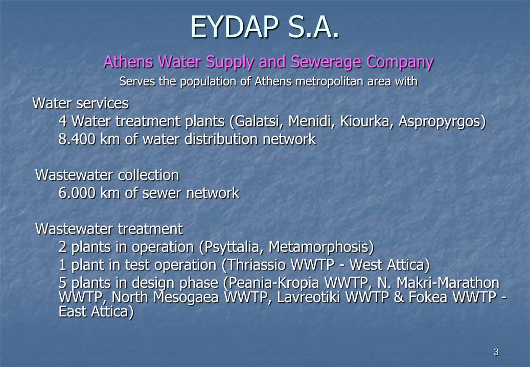
Athens Water Supply and Sewerage CompanyServes the population of Athens metropolitan area with
Water services4 Water treatment plants (Galatsi, Menidi, Kiourka, Aspropyrgos)8.400 km of water distribution network
Wastewater collection 6.000 km of sewer network
Wastewater treatment2 plants in operation (Psyttalia, Metamorphosis) 1 plant in test operation (Thriassio WWTP - West Attica)5 plants in design phase (Peania-Kropia WWTP, N. Makri-Marathon WWTP, North Mesogaea WWTP, Lavreotiki WWTP & Fokea WWTP -East Attica)
EYDAP S.A.
3

Akrokeramosinstallations
Psyttalia island
Salaminainstallations
Port of Piraeus
4

Psyttalia Wastewater Treatment Plant
Psyttalia WWTP installations were constructed by the Greek Ministry for the Environment, Physical Planning and Public Works, with European Union co-funding, in three phases:
1994 Phase A’ works completion, including wastewater pretreatment and primary treatment installations, primary sludge treatment installations, inverted siphon system for pretreated wastewater transport to Psyttalia and submerged outfall system for treated wastewater dispersion to the Saronic Gulf.
2004 Phase B’ works completion, including wastewater biological treatment installations and surplus activated sludge treatment installations.
2007 Phase C’ completion – construction of sludge thermal drying unit.
Construction Phases
5

Additionally, the following works have been constructed at Psyttalia WWTP by EYDAP S.A. with European Union co-funding:
Wastewater pretreatment unit on Salamina Island and submerged pipes for wastewater transport from Salamina to Psyttalia (2002)
Two cogeneration plants for heat and power (CHP) utilizing biogas (2001 & 2009) and
One CHP plant utilizing natural gas (2009)
Psyttalia Wastewater Treatment Plant
Construction Phases
6
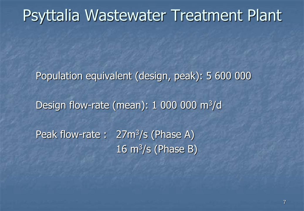
Psyttalia Wastewater Treatment Plant
Population equivalent (design, peak): 5 600 000
Design flow-rate (mean): 1 000 000 m3/d
Peak flow-rate : 27m3/s (Phase A)
16 m3/s (Phase B)
7

8
Psyttalia WWTP Flow - diagram
ELECTRIC ENERGY
BIOGAS THERMAL ENERGY
NATURAL GAS
ELECTRIC ENERGY THERMAL ENERGY
DRIED SLUDGE UTILIZATION
EFFLUENT
SLUDGE
PUMPING
GRAVITY THICKENING
(TANKS)DIGESTION
WASTEWATER INFLOW PUMPING
COGENERATION (BIOGAS)
DRYING
SCREENING
GRIT REMOVAL
PRIMARY
SEDIMENTATION
DEWATERING
MECHANICAL
THICKENING (BELTS)
FINAL SETTLING TANKS BIOREACTORS
COGENERATION
(NATURAL GAS)
Psyttalia Wastewater Treatment Plant
8

9
AkrokeramosInstallations
Wastewater PretreatmentDebris
Removal
Screening
Grit Removal
Odor Control
Twin inverted
siphon9
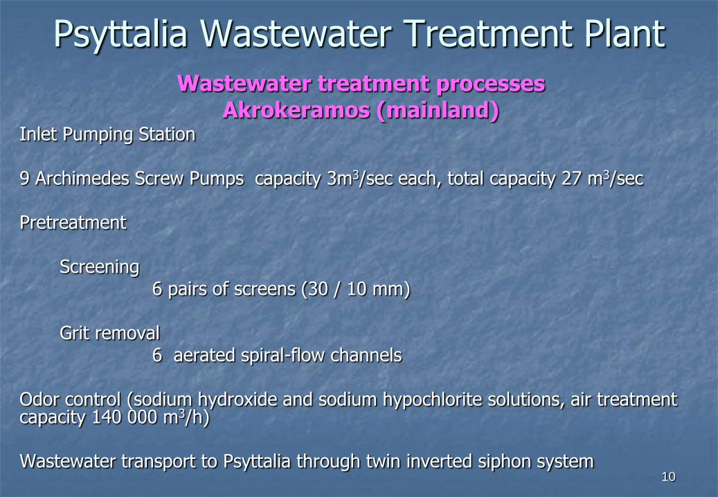
Psyttalia Wastewater Treatment PlantWastewater treatment processes
Akrokeramos (mainland)Inlet Pumping Station
9 Archimedes Screw Pumps capacity 3m3/sec each, total capacity 27 m3/sec
Pretreatment
Screening6 pairs of screens (30 / 10 mm)
Grit removal 6 aerated spiral-flow channels
Odor control (sodium hydroxide and sodium hypochlorite solutions, air treatment capacity 140 000 m3/h)
Wastewater transport to Psyttalia through twin inverted siphon system10
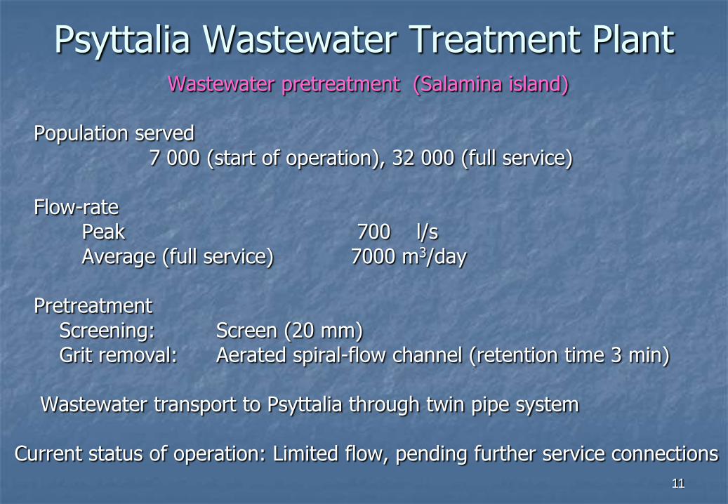
Psyttalia Wastewater Treatment PlantWastewater pretreatment (Salamina island)
Population served7 000 (start of operation), 32 000 (full service)
Flow-rate Peak 700 l/sAverage (full service) 7000 m3/day
PretreatmentScreening: Screen (20 mm)Grit removal: Aerated spiral-flow channel (retention time 3 min)
Wastewater transport to Psyttalia through twin pipe system
Current status of operation: Limited flow, pending further service connections
11

Wastewater Inlet Channel
Primary Treatment
Biological Treatment
Final SettlingFiltration
C.H.P.
Gas-holders
Sludge Thermal Drying
Sludge Digesters
12
Psyttalia Wastewater Treatment Plant

Wastewater treatment processes Psyttalia island
Primary sedimentation6 tanks (combined area 12 000 m2)
Biological treatment12 bioreactors (combined volume 300 000 m3)Organic load removal and nitrogen reduction
Final settling64 rectangular tanks (combined area 52 000 m2)
Filtration - Disinfection3 sand-filters (one spare; com. capacity 1500 m3/h) and mechanical filters 2 UV disinfection unitsProduction of process water, for use in facilities on Psyttalia
Outfall systemTwo main pipes (1870 m long each, depth 65m) Receiving waters: Inner Saronikos Gulf
Psyttalia Wastewater Treatment Plant
13

Effluent Disposal Requirements
Based on Approved Environmental Terms according to Directive 91/271/EEC :
Treated Effluent Concentration (mg/l)
BOD5 25
COD 125
Suspended Solids 35
Total Nitrogen Removal (%) >70
Psyttalia Wastewater Treatment Plant
14

Typical wastewater inflow characteristics (mg/l)
COD: 720, BOD5: 320, TSS: 350
Operation efficiency
Load reduction (%) exceeding
COD 93
BOD5 93
TSS 93
Total Nitrogen 75
Psyttalia Wastewater Treatment Plant
15
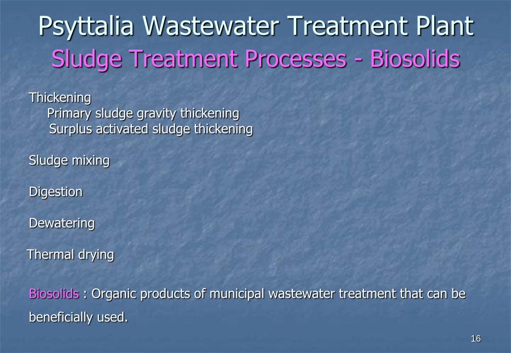
Psyttalia Wastewater Treatment Plant
Sludge Treatment Processes - Biosolids
ThickeningPrimary sludge gravity thickening Surplus activated sludge thickening
Sludge mixing
Digestion
Dewatering
Thermal drying
Biosolids : Organic products of municipal wastewater treatment that can be
beneficially used.
16

Sludge Τhickening
Primary sludge:Fine screening
Six screens (5 mm gaps) Gravity thickening facilitated / aided by use of
polyelectrolyte solution 3 tanks (combined area 1500 m2)Odor control unit (2 lines)
Waste activated sludge:Mechanical thickening aided by polyelectrolyte
14 belt thickeners (comb. capacity: 1750 m3/h)
Sludge in-pipe mixing prior to digestion
Psyttalia Wastewater Treatment Plant
17

Sludge Digestion
Method: anaerobic, mesophilic, high-rate
Installations: 8 digesters (combined volume 80 000 m3)
Type: Cylindrical, conical bottom, fixed-cover (dome-like)
Mode of operation: parallel
Biogas production from partly destruction of sludge organic content
Mixing medium: Compressed biogas
Heating medium: Water
Heating source: Cooling water from CHP plant using Biogas
Psyttalia Wastewater Treatment Plant
18

19
Psyttalia Wastewater Treatment Plant
CH4
CO2
Carbohydrates
Proteins
Lipids
Phosphorylated
Organics
Glucose
Amino-acids
Fatty Acids
Phosphates (PO4-3)
Acetic Acid
Propionic Acid
Lactic Acid
Cells (Biomass)
Cells (Biomass)
Stabilized Organic
Compounds
Extracellular
enzymes
Acid-producing
microorganisms
Methane-producing
microorganisms
Complex Organic Compounds
Hydrolysis Soluble Organic Compounds
Acids Formation
Organic Acids
Methane Formation
Anaerobic Digestion

Psyttalia Wastewater Treatment Plant
Sludge Digestion
Phase A digesters: 4Heating and mixing:
6 heat-a-mix units in each tank
Phase B digesters: 4Heating: external heat exchangersMixing: top-mounted hanging lances
20

Psyttalia Wastewater Treatment Plant
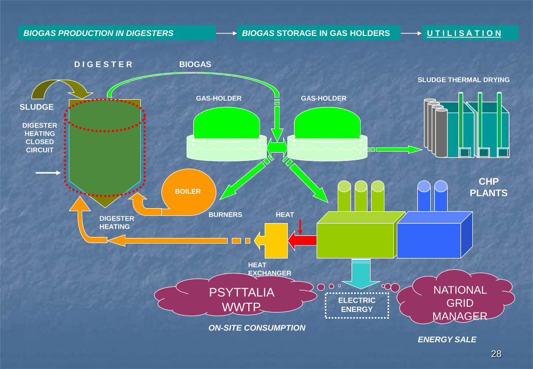
Biogas temporary storage
Biogas produced at the anaerobic digestion plant is temporarily stored in the gas-holders (two tanks with 5600 m3 capacity each) and it is utilized as a fuel at the sludge thermal drying unit and at the gas-engines of the CHP plant.
21
22
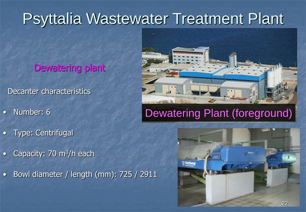
Dewatering plant
Decanter characteristics
• Number: 6
• Type: Centrifugal
• Capacity: 70 m3/h each
• Bowl diameter / length (mm): 725 / 2911
Psyttalia Wastewater Treatment Plant
Dewatering Plant (foreground)
2222

23
Cogeneration plant for Heat and Power
production (CHP)
utilizing natural gas (gas-turbine)
Psyttalia Wastewater Treatment Plant
Sludge Thermal Drying
Sludge Thermal Drying
Unit
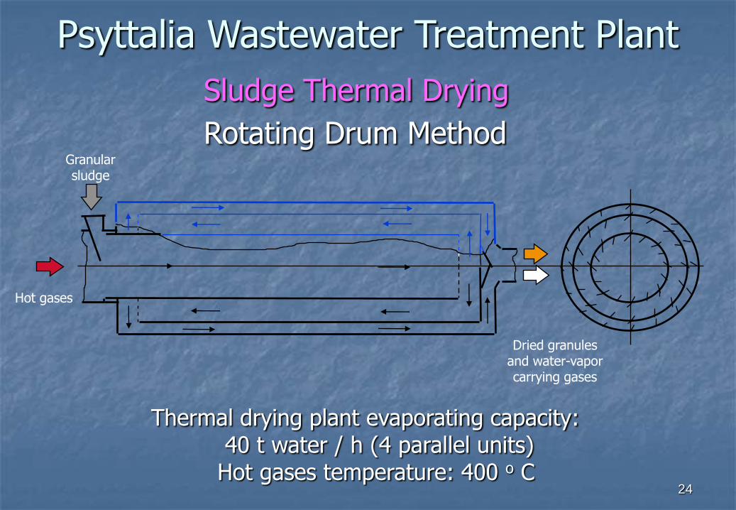
Hot gases
Granular sludge
Dried granulesand water-vapor carrying gases
Thermal drying plant evaporating capacity: 40 t water / h (4 parallel units)
Hot gases temperature: 400 o C
Sludge Thermal Drying
Rotating Drum Method
Psyttalia Wastewater Treatment Plant
24
25
Utilization of Biogas produced at Psyttalia WWTP
Psyttalia Wastewater Treatment Plant
25

Psyttalia Wastewater Treatment Plant
The need for sustainable development combines environmental protection with
meeting energy needs and in this framework the full utilization of available renewable
energy sources including biogas, is a continuous necessity and one of the major
goals for Psyttalia WWTP.
26

Sludge Digestion Biogas
Composition of biogas produced from the sludge anaerobic digestion process
• Methane CH4 61 - 65 %
• Carbon Dioxide CO2 34 - 38 %
• Nitrogen Ν2 0.05 %
• Oxygen Ο2 0.0001 %
• Hydrogen Sulfide H2S 1000 - 2000 ppm
Psyttalia Wastewater Treatment Plant
27
PSYTTALIA
WWTP
NATIONAL
GRID
MANAGER
SLUDGE THERMAL DRYING
CHP
PLANTS
BIOGAS
GAS-HOLDERGAS-HOLDER
BURNERS
BOILER
DIGESTER
HEATING
HEAT
EXCHANGER
ELECTRIC
ENERGY
ON-SITE CONSUMPTION
ENERGY SALE
DIGESTER
HEATING
CLOSED
CIRCUIT
HEAT
SLUDGE
D I G E S T E R
BIOGAS PRODUCTION IN DIGESTERS BIOGAS STORAGE IN GAS HOLDERS U T I L I S Α T I O N
28
29
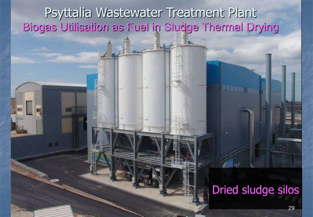
Dried sludge silos
29
Psyttalia Wastewater Treatment PlantBiogas Utilisation as Fuel in Sludge Thermal Drying

THERMAL DRYING Psyttalia WWTP - Rotating Drum Method
30

Thermal Drying - Dried product characteristics
• Satisfying US EPA 503 Class A specifications for hygienized sludge
• Particle size 1 – 5 mm
• Maximum temperature 45oC
• Dried solids content (%) 90 – 95, mean 92
• Maximum dust (<75 μm) content < 1% w/w
Psyttalia Wastewater Treatment Plant
31
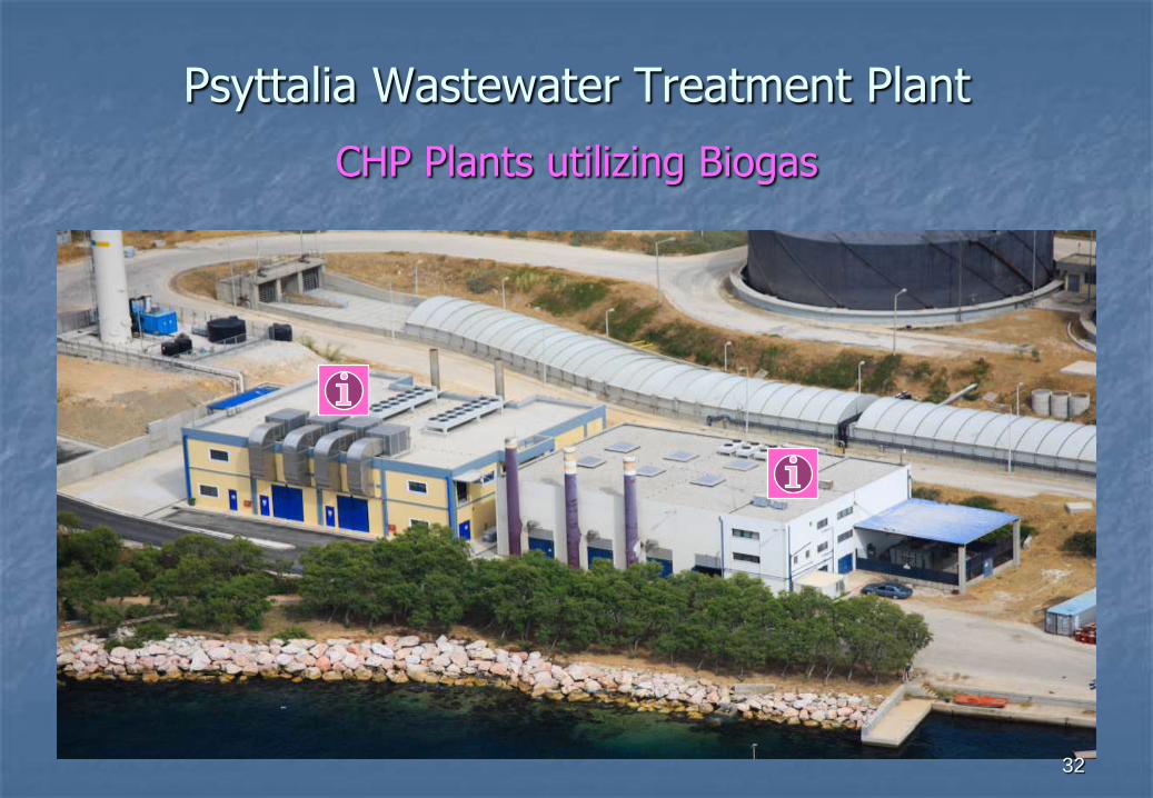
Psyttalia Wastewater Treatment Plant
CHP Plants utilizing Biogas
32

GAS - HOLDERS
ELECTRIC
ENERGY
THERMAL
ENERGY
THERMAL
ENERGY
DIGESTERS
CONSUMPTION
ON-SITE
SALE TO
NATIONAL GRID
ELECTRIC
ENERGY
SALE TO
NATIONAL GRID
BIOGAS UTILIZATION AS FUEL IN CHP PLANTS
FOR ELECTRIC POWER AND HEAT PRODUCTION
CHP PLANT
7,14 ΜWe
Phase A’
Power gridPhase B’Power grid
Power supply to
Phase B’
installations at
Psyttalia WWTP
Commisioning
2001Commisioning
2009
Power supply to
Phase A’
installations at
Psyttalia WWTP
Electric energy
surplusElectric energy
surplus
CHP PLANT
4,25 ΜWe
33CONSUMPTION
ON-SITE33

TECHNICAL CHARACTERISTICS OF 7.14 MWe CHP PLANT
Number of Gas-Engines 3 Mechanical Power 2 521 kW Electrical Power Capacity 7.14 MWe Heat Capacity 10.35 MWth Number of Pistons 12V Frequency 1 000 rpm Peak Biogas Consumption 3 x 1 000 m3/h Biogas Inflow Pressure 14 mbar Fuel Pressure (Biogas after compression) 3.2 bar Generators Capacity 2 900 KVA Generators Output Voltage 3 300 V Electric Current Frequency 50 Hz Voltage to Grid 20 KV
34
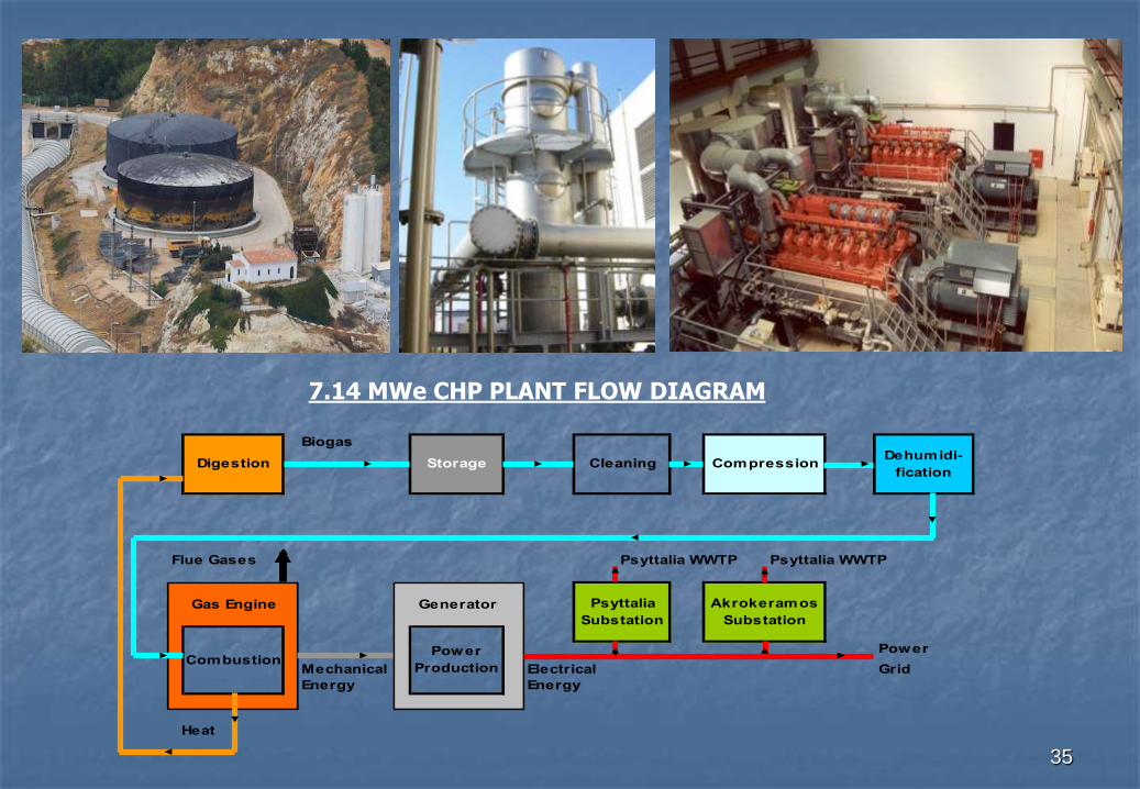
7.14 MWe CHP PLANT FLOW DIAGRAM
35
Biogas
Psyttalia WWTP Psyttalia WWTP
Power
Mechanical Electrical Grid
Energy Energy
Heat
Flue Gases
Gas Engine Generator
CombustionPower
Production
CompressionDigestionDehumidi-
fication
Psyttalia
Substation
Akrokeramos
Substation
Storage Cleaning
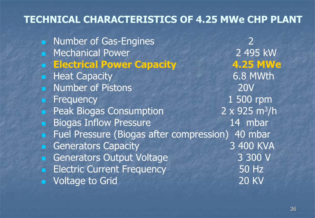
TECHNICAL CHARACTERISTICS OF 4.25 MWe CHP PLANT
Number of Gas-Engines 2 Mechanical Power 2 495 kW Electrical Power Capacity 4.25 MWe Heat Capacity 6.8 MWth Number of Pistons 20V Frequency 1 500 rpm Peak Biogas Consumption 2 x 925 m3/h Biogas Inflow Pressure 14 mbar Fuel Pressure (Biogas after compression) 40 mbar Generators Capacity 3 400 KVA Generators Output Voltage 3 300 V Electric Current Frequency 50 Hz Voltage to Grid 20 KV
36
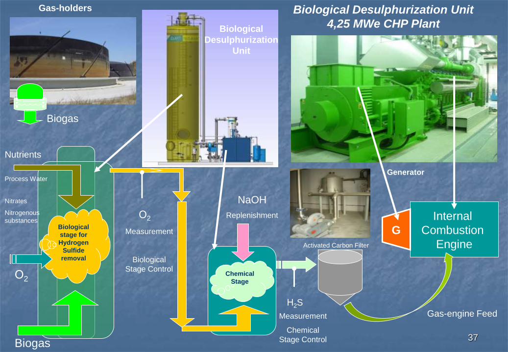
Internal
Combustion
Engine
GBiological
stage for
Hydrogen
Sulfide
removal
Chemical
Stage
Biogas
Ο2
Nutrients
Ο2
NaOH
Replenishment
Η2S
Activated Carbon Filter
Gas-engine Feed
Gas-holders
Biogas
Measurement
Biological
Stage Control
Measurement
Chemical
Stage Control
Biological
Desulphurization
Unit
Process WaterGenerator
Biological Desulphurization Unit
4,25 MWe CHP Plant
Nitrates
Nitrogenous
substances
37

Production and Utilisation of Biogas
Biogas Thermal Energy: 6.4 kWhth / m3
Biogas Production (mean) : 65 000 m3 / day 24 x 106 m3 / year
70% - 90% to CHP & Thermal Drying PlantsBiogas Utilization
10% - 30% for Digester heating
Electricity Production from CHP Plants (mean): 35 000 MWhe/year
Psyttalia Wastewater Treatment Plant
38

39
Environmental , Economic and other Benefits
from Biogas Utilization
Fuel savings
Considerable reduction of power purchasing cost
Income from sale of surplus power
Reduced emissions of pollutants to the atmosphere
Gain of know-how
New jobs creation
Psyttalia Wastewater Treatment Plant