GraverMach AT - GRS.com · A properly sharpened graver or similar tool is required to cut through...
30
NOTICE This engraving system requires clean, dry, oil-free air. An oil-free compressor is recommended for use with this system. For any oil-type compressors, an oil-removal filter (coalescing type) in the air supply line to this engraving system MUST BE INSTALLED AND IN USE. OIL OR WATER CONTAMINATION IS NOT COVERED BY WARRANTY. For help with ordering or installing an oil-removal filter, or for guidance with operation or maintenance, please contact GRS or an authorized GRS dealer. To send a request for assistance via electronic formats, e-mail [email protected] or visit: http://www.grstools.com/customerservice/ Important notes are highlighted in yellow or marked in red. GraverMach ® AT OPERATION AND MAINTENANCE MANUAL #004-965 READ THIS MANUAL ENTIRELY BEFORE CONNECTING TO POWER. Damage not covered by the warranty may result from not following the instructions and maintenance in this manual. ORIGINAL INSTRUCTIONS
-
Upload
trankhuong -
Category
Documents
-
view
219 -
download
0
Transcript of GraverMach AT - GRS.com · A properly sharpened graver or similar tool is required to cut through...

NOTICEThis engraving system requires clean, dry, oil-free air. An oil-free compressor is recommended for use with this system. For any oil-type compressors, an oil-removal filter (coalescing type) in the air supply line to this engraving system MUST BE INSTALLED AND IN USE.
OIL OR WATER CONTAMINATION IS NOT COVERED BY WARRANTY.
For help with ordering or installing an oil-removal filter, or for guidance with operation or maintenance, please contact GRS or an authorized GRS dealer.
To send a request for assistance via electronic formats, e-mail [email protected] or visit:
http://www.grstools.com/customerservice/
Important notes are highlighted in yellow or marked in red.
GraverMach® ATOPERATION AND MAINTENANCE MANUAL
#004-965
READ THIS MANUAL ENTIRELY BEFORE CONNECTING TO POWER.
Damage not covered by the warranty may result from not following the instructions and maintenance in this manual.
ORIGINAL INSTRUCTIONS

Manual ContentsImportant Notice For Operators . . . . . . . . . . . . . . . . . . . . . . . . . . .1
Required Equipment & Important Notes . . . . . . . . . . . . . . . . . . . . .2
Introduction, Unpacking The Unit . . . . . . . . . . . . . . . . . . . . . . . . . .4
Setup & Connections . . . . . . . . . . . . . . . . . . . . . . . . . . . . . . . . . . . .6Mount & Connect Air Filter, Connect Foot Throttle, Connect Handpiece(s), Using an Air-Driven Rotary Handpiece, Connect Electrical Power
Operation . . . . . . . . . . . . . . . . . . . . . . . . . . . . . . . . . . . . . . . . . . . . .8Strokes Per Minute (SPM), Fine Adjustments for Handpiece Operation,Handpiece Adjustment Troubleshooting, Foot Throttle Operation, Handpiece Operation, Adjustments Using the Bias Control
Airtact Operation . . . . . . . . . . . . . . . . . . . . . . . . . . . . . . . . . . . . . . 12Connecting and Operating, Airtact Air Pressure Adjustments
Maintenance . . . . . . . . . . . . . . . . . . . . . . . . . . . . . . . . . . . . . . . . . 14Handpiece, Foot Throttle, GRS Ultra 850 Rotary Handpiece
Important Notices . . . . . . . . . . . . . . . . . . . . . . . . . . . . . . . . . . . . . 15GRS Progressive Foot Throttle Owners, Air Contaminants & Water Accumulation
Palm Pad Fine Adjustment . . . . . . . . . . . . . . . . . . . . . . . . . . . . . . 16Type-E Palm Pads, Forming the Rubber Control Flap
Service & Repair . . . . . . . . . . . . . . . . . . . . . . . . . . . . . . . . . . . . . . 17
Parts Lists . . . . . . . . . . . . . . . . . . . . . . . . . . . . . . . . . . . . . . . . . . . 18
Wiring, Hose Diagrams . . . . . . . . . . . . . . . . . . . . . . . . . . . . . . . . .26
Warranty . . . . . . . . . . . . . . . . . . . . . . . . . . . . . . . . . . . . . . . . . . . .28
READ THIS MANUAL ENTIRELY BEFORE CONNECTING TO POWER.
Damage not covered by the warranty may result from not following the instructions and maintenance in this manual.

1
FOR PROPER OPERATION, THIS SYSTEM REQUIRES:• Included 24-volt power converter connected to a properly grounded electrical
power outlet
• Clean, dry, oil-free air provided by an air compressor
• A compatible GRS pneumatic handpiece
• A graver or similar tool
• A clean, sturdy work surface with adequate lighting
• Workholding device or material
IMPORTANT NOTICE FOR OPERATORSRead this manual thoroughly before operation. The manufacturer is not responsible for injury resulting from improper operation or when used by untrained operators.
Do not modify this equipment or remove warning labels. Modifications can increase risks to the operator. Do not use this equipment if it is damaged. This equipment allows the use of small sharp cutting tools that can break suddenly. Always wear eye protection appropriate for each application, and protect hands from sharp edges.
Like other power tools, this device exposes the operator to mechanical vibration. If any user experiences discomfort, pain, numbness, aching, etc., in their hands, fingers, arms, or related joints, discontinue use and consult with an appropriate health professional.
Although this equipment does not generate dust itself, the tools used in the handpieces may do so. When sharpening tools, the user should take appropriate steps to avoid dust inhalation. Certain tool materials generate harmful dust while being ground or sharpened.
The proper use of this equipment does not generate significant or harmful noise emissions.

2
• Included 24-volt power converter USE ONLY THE SUPPLIED 24-VOLT POWER CONVERTER. The included power converter may be connected to any properly grounded single-phase source of AC power within a voltage range of 100 to 240 V, 50 or 60 Hz. If necessary, use the supplied grounded 2-prong plug adapter or other suitable adapter. The power converter must be used with a suitable grounded electrical system. Using it with an ungrounded system could expose the equipment to electrical damage. Do not use older generation power converters. If a replacement is needed, contact GRS or an authorized GRS dealer to order #022-987. DO NOT OPERATE THE MACHINE WITHOUT A COMPRESSED AIR SUPPLY. Compressed air not only provides the handpiece with power, it lubricates internal components including the rotary air valve. Do not add oil or any lubricant to the compressed air supply.
• A compatible GRS pneumatic handpiece All GRS Standard Handpieces and GRS Airtact Handpieces are compatible with this system. DO NOT USE SYSTEM 3 OR GRAVERMEISTER HANDPIECES. Please contact GRS or an authorized GRS dealer for a complete list of compatible handpieces.
• A graver or similar tool A properly sharpened graver or similar tool is required to cut through the surface of metal and other materials; use with care. The dust created while sharpening some tool materials may present a health risk. Please contact GRS or an authorized GRS dealer for a list of available gravers and tools.
READ THIS MANUAL ENTIRELY BEFORE CONNECTING TO POWER.
Damage not covered by the warranty may result from not following the instructions and maintenance in this manual.
REQUIRED EQUIPMENT & IMPORTANT NOTES

3
• Clean, dry, oil-free air from an air compressor Oil-free compressors are ALWAYS RECOMMENDED. When using an oil-lubricated compressor, install an oil-removal filter (coalescing type – GRS #004-579 or equivalent) in the air supply line to this engraving system. Damage due to oil or water contamination IS NOT COVERED BY WARRANTY. Even slight amounts of oil can damage internal parts and cause erratic handpiece operation. The supplied final filter is not capable of removing large amounts of water, oil, or contaminants. See Setup & Connections for mounting the supplied air filter to engraving system. If compressed air supply has excessive water, oil, or contaminants, an additional filter/water trap and oil-removal filter (coalescing type) must be installed ahead of the engraving system. GraverMach® AT requires a compressed air supply with minimum pressure 45 psi (3 bar) and maximum pressure 120 psi (8 bar). The compressed air supply must have a minimum flow capacity of 1.4 CFM [ft³/min] or 40 LPM [L/min]. To ensure a stable compressed air supply, the user should consider an additional air regulator to adjust the air pressure to 45-60 psi (3-4 bar) before it enters the GraverMach®.
• A sturdy surface with adequate lighting Make use of a heavy workbench or suitable solid furniture to support this equipment, workpiece, and any additional equipment and supplies. Adequate lighting allows clear sight, and may help prevent accidents and reduce fatigue. Placement of this engraving system on the bench is solely user preference and may be determined by left or right hand use during operation.
• Workholding device or material For best results, using a workholding device or material is highly recommended. Properly secure the workpiece to ensure user safety and to guard the piece from damage while working. GRS manufactures several sizes and types of workholding devices, such as the MagnaBlock, Positioning Vise, MicroBlock vise, Thermo-Loc material, and the BenchMate™.
REQUIRED EQUIPMENT & IMPORTANT NOTES (continued)
DO NOT OPERATE ENGRAVING SYSTEM WITHOUT AN ACTIVE AIR SUPPLY CONNECTED.
The air supply lubricates the rotary valve as the air passes through the system. No additional lubrication is required.

4
FIG. 1 • GraverMach® AT Overview
A B C
DE F
G
H
I
L
J
K
M
Front View
O
N
Q
P
SR T
VW
U
Back View
O
N

5
INTRODUCTIONThe GraverMach® AT is an engraving system engineered and manufactured under the GRS Tools line of products by Glendo Corporation in the United States of America. This system is designed for assistance in creating unique works in metal, stone, wood, ivory, and many other materials.
UNPACKING THE UNITIMPORTANT SHIPPING NOTEWhen unpacking a new GraverMach® AT, notice the screw protruding from the bottom of the machine (FIG. 1.V). This screw is holding the motor mount assembly to protect it from damage during shipping. Remove screw before operation. Use a 7/16" wrench / socket or an adjustable-end wrench to remove screw and washer, then store both by inserting into the rubber grommet located on the back (FIG. 1.S), as shown in the illustration.
For any shipping or transport of this unit, the screw and washer MUST BE REPLACED at the bottom of the unit to prevent damage to the motor mount assembly while in transit.
NEVER OPERATE WHILE ON SIDE. Always use the system in a vertical position (FIG. 1).
GraverMach® AT FIG. 1 Diagram
A. Airtact air pressure gaugeB. Airtact air pressure control knobC. Power on/off buttonD. Bias control knobE. Primary air pressure gaugeF. Primary air pressure control knobG. Handpiece selector knob (for J and K)H. Strokes Per Minute (SPM) dialI. Airtact hand/foot control selector knobJ. Airtact Handpiece twist-lock fittingsK. Standard Handpiece push-to-connect fittingsL. Auxiliary air open/close knobM. Air supply input push-to-connect fitting
N. Air filterO. Air filter bowl drain knobP. Air filter output push-to-connect fittingQ. Air filter input push-to-connect fittingR. Foot Throttle push-to-connect fittingS. Rubber grommet for stabilizer screw and washer storage—See UNPACKING THE UNITT. Auxiliary Handpiece push-to-connect fittingU. 24-volt power receptacleV. Motor mount assembly stabilizer screw W. Reservoir drain plug (drain located in bottom of base)

6
A. Airtact Handpiece fittingsB. Standard Handpiece fittingsC. Air filter fittingsD. Foot Throttle fittingE. Auxiliary Handpiece fittingF. 24-V power converter receptacleG. 24-V power converter (#022-987)
A
B
C.1D
FIG. 3 • Hose Connections
EF
G
C.2
1. Remove top screw from hole.
2. Place screw through top hole on air filter bracket. Tighten screw. Lower screw keeps filter from swinging freely; do not tighten or remove.
3. Power off system and air supply. Connect supplied short black hose (#044-229) to straight fitting on filter. Connect other end to “Air Input” fitting. To mount elsewhere, use supplied longer black hose (#044-069) — see page 18.
4. Connect hose from air supply to filter fitting marked “N”.
FIG. 2 • Mounting Air Filter to Side
7
9
6
10
811
13
4
Air Filter Knob
Drain water from filter daily. Turn knob clockwise (from top view) to open. Drain. Turn knob counter-clockwise to close valve.
A
A
Turn Clockwise
2
NOTE: If air supply hose is larger than 1/4" (6.35 mm) OD, either replace the push-to-connect fitting with the included barbed fitting and attach the air supply hose or purchase a reducer to decrease the OD to 1/4" (6.35 mm).

7
MOUNT & CONNECT AIR FILTERMount air filter in a location where the air filter may be drained daily (see FIG. 2.A). Refer to FIG. 2 for instructions on mounting the air filter to side of system.
Power off engraving system and air supply. Insert appropriate hose (see FIG. 2.3) into the fitting until the hose stops and is secure. Power on engraving system and air supply to check for leaks and improper connections; air should not escape through any hose or fitting. If air leaks, power off system and air supply. Locate leaks and correct any improper connections. To disconnect from a push-to-connect fitting, press in on the orange ring while gently pulling out the hose.
CONNECT FOOT THROTTLEPlace foot throttle on the floor in a convenient position. Extend throttle hose to back of system (FIG. 3.D) to insert into fitting marked “THROTTLE CONNECTION”. The hose should not be pinched or kinked. NOTE: The foot throttle varies handpiece power by controlling the amount of air that flows from the handpiece. While the throttle is depressed, it is normal for air to be released. The user may hear the air being released at times during operation.
CONNECT HANDPIECE(S)Two handpieces may be connected; only one handpiece can be in operation at any time. Each Standard Handpiece uses a single “B” push-to-connect fitting (FIG. 3.B); each Airtact Handpiece simultaneously uses one “A” twist-lock fitting (FIG. 3.A) and one “B” push-to-connect fitting (FIG. 3.A and B).
Connect desired handpiece(s) accordingly. The handpiece selector knob above the fittings allows use of either handpiece 1 or handpiece 2 (FIG. 1.G). NOTE: The handpiece selector knob should stop completely when turned to either side, with the line on the knob parallel to the bench top or floor.
USING AN AIR-DRIVEN ROTARY HANDPIECEThe auxiliary push-to-connect fitting (FIG. 3.E) is a straight flow air port that is limited to 40 psi (2.7 bar) maximum. This is the fitting for a rotary handpiece or other pneumatic tool. The knob is a twist-open/twist-close valve on the front of system (FIG. 1.L).
DO NOT EXCEED 35 psi (2.4 bar) when using the GRS Ultra 850 Rotary Handpiece.
CONNECT ELECTRICAL POWERDO NOT OPERATE ENGRAVING SYSTEM
WITHOUT AN ACTIVE AIR SUPPLY CONNECTED. Insert the converter cord into receptacle on engraving system (FIG. 3.F and G). Connect the electrical power cord into the 24-volt power converter. Connect the 3-prong power cord into a properly grounded power outlet, using adapters as needed. See pages 2-3 for details.
SETUP & CONNECTIONS

8
OPERATIONSTROKES PER MINUTE (SPM)Stroke speed is a matter of personal preference and experience. The SPM dial (FIG. 4.C) settings are approximate and range from 400–8,000 SPM.
Lower speeds are used for stippling, matting, and similar techniques. Mid-range speeds are used for maximum-power tasks. Higher speeds are used for fine cuts and finishes. Experiment with the settings to better understand how the SPM relates to technique.
FINE ADJUSTMENTS FOR HANDPIECE OPERATION
PROPERLY ADJUSTING THE ENGRAVING SYSTEM IS THE SINGLE MOST IMPORTANT OPERATION TO LEARN. Each handpiece has a normal SPM range. Operating outside this range can produce erratic results.
SPECIAL NOTE: When powered on, the system pushes a small amount of air through the electrically-controlled air solenoid valve. When powered off, the system seals the valve, making a “pop” and “hiss” sound. This allows the system to be powered off while the air compressor remains on—without loss of air in the compressor tank.
• Power on the air compressor and allow tank to fill. Wait for the compressor to cycle off.
• Power on the GraverMach® AT. Turn the bias control knob clockwise until closed. Turn the handpiece selector knob to choose connected handpiece. Turn the hand/foot selector control knob to select “foot” control. See Airtact Operation for using “hand” control.
• Turn the SPM dial (FIG. 4.C) to 2300. Turn the primary air pressure control knob (FIG. 4.B) clockwise until the air pressure gauge displays 5 psi (0.4 bar).
• Hold the selected handpiece vertically near either ear as shown in FIG. 5.
• WITHOUT operating the throttle, slowly increase the air pressure until the handpiece begins to buzz. The handpiece will vibrate, then knock, as the pressure increases. Stop adding air pressure immediately after the knocking stops. This is the perfect air pressure operating range for the selected handpiece model.
See chart on page 9 for an alternative adjustment method.
A B
C
FIG. 4 • Primary Control Knobs
A. Bias control knobB. Primary air pressure control knobC. Strokes Per Minute (SPM) dial Make sure the bias control knob is closed before adjusting the machine.
FIG. 5

9
HANDPIECE FINE ADJUSTMENT SETTINGS
Handpiece Item Number TypeNormal Operating
RangeStrokes Per Minute
Normal Air Pressure Rangepsi (bar)
Recommended Initial Setting
Strokes Per Minute Air Pressure psi (bar)
Magnum 004-940 800-3400 18-22 psi (1.2-1.5 bar) 2400 20 psi (1.4 bar)
901 004-901, 004-910 Standard 1400-4000 17-22 psi (1.2-1.5 bar) 2400 19 psi (1.3 bar)Fine 1400-4000 12-15 psi (0.8-1.0 bar) 2400 13 psi (0.9 bar)
Monarch 004-921, 004-926 Standard 2000-5000 10-13 psi (0.7-0.9 bar) 3000 11 psi (0.8 bar)Fine 2000-5000 6-8 psi (0.4-0.6 bar) 3000 7 psi (0.5 bar)
Maestro MX 004-909 600-3200 18-22 psi (1.2-1.5 bar) 2200 20 psi (1.4 bar)
Maestro EX 004-905 800-3600 17-22 psi (1.2-1.5 bar) 2200 19 psi (1.3 bar)
Maestro 004-947 2000-5000 10-13 psi (0.7-0.9 bar) 3000 11 psi (0.8 bar)
QC 720 004-720 400-3000 18-26 psi (1.2-1.8 bar) 1600 22 psi (1.5 bar)
QC 710 004-710 800-3000 20-24 psi (1.4-1.7 bar) 1800 21 psi (1.4 bar)
610 Hammer 004-610, 004-609 800-3000 20-24 psi (1.4-1.7 bar) 1800 21 psi (1.4 bar)
QC 801 004-801, 004-810 (obsolete) 1400-4000 20-24 psi (1.4-1.7 bar) 2400 22 psi (1.5 bar)
506 Large 004-506 (obsolete) 400-3000 18-26 psi (1.2-1.8 bar) 1600 22 psi (1.5 bar)
508 Standard 004-508 (obsolete) 800-3000 18-22 psi (1.2-1.5 bar) 2000 20 psi (1.4 bar)
Alternatively, the settings in the chart may be used for adjusting the selected handpiece; this method is not as precise. Set the SPM dial and the air pressure control knob to the Recommended Initial Setting for the selected handpiece.

10
OPERATION (continued)
HANDPIECE ADJUSTMENT TROUBLESHOOTING The system will be difficult to control if the air pressure or SPM is incorrect. Use the lowest air pressure setting to provide proper operation; do not set the air pressure higher than needed.
• Handpiece vibrates or knocks without using the Foot Throttle: air pressure is too low; increase to proper air pressure.
• Handpiece power decreases at full throttle: air pressure is too low or the SPM is too high; reset pressure or SPM.
• Handpiece does not operate within 3/8" (9.525 mm) of depressing foot throttle: air pressure is too high; decrease to proper air pressure.
Make fine adjustments in air pressure or SPM until proper operation is attained. The handpiece will operate smoothly and predictably once adjusted properly. With more experience, experiment with variations in air pressure and SPM to suit preferences.
FOOT THROTTLE OPERATIONFor foot throttle operation, set the engraving system to “foot” control as follows.
• Set the hand/foot control selector knob to the “foot” control position (FIG. 1. I ).
• Place foot on throttle as shown in FIG. 6, with heel completely on the Foot Throttle and not on the floor.
• Before depressing foot throttle, position handpiece and tool properly. The tool should rest firmly on the material surface before operating the foot throttle.
After handpiece is adjusted properly, depress the foot throttle to activate the handpiece. To increase power when cutting deeper, depress the Foot Throttle as needed to increase handpiece power. It may take practice to coordinate foot action with the need for more power.
Rely on increasing the power provided by the foot throttle to the handpiece instead of manually pushing the handpiece through the cut. Manual pushing is an incorrect use of the handpiece and can result in the tool slipping.
At the start of the cut, smoothly increase power; as more power is needed, depress the foot throttle more. As the cut reaches the end, gradually reduce foot throttle pressure and quickly guide the graver up and out.
FIG. 6

11
OPERATION (continued)
HANDPIECE OPERATIONUnlike traditional or push engraving where a firm grip and manual forward force is required, the GRS pneumatic handpiece requires only a light grip and guidance.
Relax, allowing the engraving system to move the tool forward and through the material with guidance. Most graver slips are due to manual hand pushing and an overly-firm grip on the handpiece.
A tight grip actually lessens impact power. For heavy work, decrease grip while increasing power with the foot throttle; an increasingly relaxed grip will increase the power. However, do not lose control while guiding the tool.
For general cutting techniques, position the handpiece as in FIG. 7.A; this is similar to holding a dinner knife. For stippling, hammering, or similar techniques, position the handpiece as in FIG. 7.B; this is similar to holding a pencil.
For hammering work, press the hammer tip down firmly to the material surface and then operate the foot throttle. This system is not like a flexible-shaft hammer; do not operate the hammer tool by holding the tip slightly above the surface. Use just enough downward pressure to keep the hammer in place while working.
ADJUSTMENTS USING THE BIAS CONTROLUse the bias control to adjust the starting position of the foot throttle. This feature may be useful for fine detail work such as bulino engraving. Open the bias control fully to activate the handpiece without depressing the foot throttle. This feature may be useful for stippling or hammering.
• Turn the primary air pressure control knob (FIG. 4.B) to add 1-2 psi (0.07-0.14 bar) air pressure to the current setting.
• Turn the bias control (FIG. 4.C) slightly to open the bias valve, just until the handpiece is activated; then slowly close the bias valve when the handpiece stops stroking. Note the foot throttle requires less pressure to activate the handpiece.
FIG. 7
7.B7.A

12
AIRTACT OPERATION
CONNECTING AND OPERATINGThe GRS Airtact touch-control system is integrated into this engraving system, adding the ability to use hand-controlled throttle. A Standard Handpiece will not operate as an Airtact Handpiece; it may only be operated by the foot throttle.
However, the knob on a Standard Handpiece can be replaced with an Airtact-ready knob for hand-controlled throttle. Additionally, the Standard Handpiece may be modified with the addition of a barrel-mounted Thumb / Finger Touch Element for hand-controlled throttle.
• If engraving system is powered on, press the on/off button (FIG. 8.C) to power off. This closes the air valve.
• Connect the smaller hose to the Airtact Handpiece fitting 1 (FIG. 8.G) by gently twisting the hose end connector half a turn clockwise until secure.
• Connect the larger handpiece hose to the Standard Handpiece fitting 1 (FIG. 8.H).
• Repeat with fittings 2 to add second handpiece.
• Use Handpiece Selector Knob (FIG. 8.D) to select desired handpiece for operation.
• Press the on/off button to power on the system. Check hoses for leaks and correct as needed.
• Turn the hand/foot selector knob to “hand” control (FIG. 8.E). Set Airtact air pressure as follows.
FIG. 8 • Airtact Operation
A. Airtact air gaugeB. Airtact air pressure control knobC. Power on/off buttonD. Handpiece selector knobE. Hand/foot control selector knobF. Strokes Per Minute (SPM) dialG. Airtact Handpiece fittingsH. Standard Handpiece fittings
C
H
FG
D
BA
E
Airtact Handpiece: Throttle operated by pressure applied to Palm Pad.
Standard Handpiece: Throttle operated by pressure applied to Foot Throttle (not shown).
Comparison of Standard and Airtact Handpieces

13
AIRTACT OPERATION (continued)
AIRTACT AIR PRESSURE ADJUSTMENTSAfter correctly connecting Airtact Handpiece hoses as previously described, follow the instructions in section Fine Adjustments for Handpiece Operation and then continue with this section.
Once handpiece is properly adjusted, the Airtact air pressure must be set. The Airtact touch-control system includes a separate air pressure gauge and an air pressure control knob (FIG. 8.A and B), located above the bias control knob and the primary air pressure control knob.
At approximately 12 psi (0.8 bar), the Airtact touch-control system will provide full power for any handpiece. A lower setting will limit range of power; this decreases the operating power in the available range.
Reducing the Airtact pressure may be desired for certain fine applications, such as fine shading. The limited power allows for a narrow range that provides predictable results, restricting the depth of shade lines. Try 4-5 psi (0.3 bar) for better control during fine shading. See FIG. 9.
For automatic, constant power without handpiece activation, place the included closed-end twist-lock cap over the Airtact fitting for the selected handpiece. This feature allows for stippling, hammering, or similar techniques where multiple hits are required with full, constant power.
To check for proper handpiece air flow and connection, place the supplied closed-end twist-lock cap (installed on fitting as delivered from manufacturer) on the fitting to provide full power without activation. If handpiece does not have full power, check and then correct problems in connections and air pressure settings before continuing.
The engraving system is now ready for operation with both Standard Handpieces using the foot throttle and Airtact Handpieces using hand control.
FIG. 9
0 psi 12 psi
0 psi 12 psi0.8 bar0.3 bar0 bar
0 bar 0.8 bar
4-5 psi
Full power at 12 psi (FIG. 8.A) Airtact Pressure
Limited power at 4-5 psi (FIG. 8.A) Airtact Pressure

14
MAINTENANCEHANDPIECE Keep the handpiece clean for proper operation. Cleaning is necessary if operation becomes sluggish, erratic, or fails. Refer to FIG. 10 and the instructions below for the proper way to clean a handpiece.
• Remove the piston and spring from the handpiece.
• Wrap each separately in a sheet of writing or printing paper. DO NOT USE paper towel, tissue, or newsprint.
• Hold the wrapped piece. Buff and polish each piece with the paper to remove any dirt or residue.
• Remove piece from paper. For grooved pistons, fold paper to create a thick edge. Insert the paper edge in each piston groove. Use the same folded paper to clean open space in spring.
• Twist the paper to a point that will fit into the handpiece barrel. Insert and rotate the paper to buff and polish the inside until clean.
• Reassemble handpiece.
IMPORTANT NOTE: DO NOT LUBRICATE PISTON, SPRING, OR BORE.
FOOT THROTTLEThe throttle requires little maintenance with proper use. Remove any dust, debris, and metal chips from foot throttle to clean periodically. Place a drop of oil on the throttle hinges to prolong spring life and prevent rust. When sweeping or vacuuming, place foot throttle on bench or chair.
GRS ULTRA 850 ROTARY HANDPIECERefer to the GRS 850 operating instructions for routine maintenance of the rotary handpiece.
DO NOT EXCEED 35 psi (2.4 bar) during operation.
FIG. 10

15
IMPORTANT NOTICESGRS PROGRESSIVE FOOT THROTTLE OWNERSThe GRS Progressive Foot Throttle will operate properly with this engraving system. Attach the GRS Progressive Foot Throttle to the “THROTTLE CONNECTION” push-to-connect fitting on the back of the system.
AIR CONTAMINANTS AND WATER ACCUMULATIONIf large amounts of water and contaminants are in the air supply to the system, the bowl must be drained frequently to prevent water from entering the rotary valve, hoses, handpiece, etc. Check all filters, bowls, hoses, etc., twice a week to prevent accumulation.
Additionally, the filter element must be cleaned and/or replaced frequently. If moisture is noted in the handpiece or throttle hoses, power off system immediately. Purge air from system, drain filter bowl, and proceed as follows:
• Disassemble and clean handpiece(s). Reassemble.
• Set primary air pressure to 10 psi (0.7 bar). Power on the system to purge moisture from valves, hoses, etc.
• Locate the drain plug to the internal air reservoir (FIG. 1.W). Use a 3/16" hex wrench to remove the plug; drain any moisture from reservoir. Replace drain plug.
• Before powering on engraving system, locate source of moisture and correct problem. An additional filter or water trap in the air line may be necessary.
16
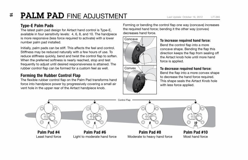
Type-E Palm Pads The latest palm pad design for Airtact hand control is Type-E, available in four sensitivity levels: 4, 6, 8, and 10. The handpiece is more responsive (less force required to activate) with a lower number palm pad installed.Initially, palm pads can be stiff . This aff ects the feel and control. Stiff ness may be reduced naturally with a few hours of use. To reduce stiff ness quickly, bend and twist the control fl ap to soften. When the preferred softness is nearly reached, stop and test frequently to adjust until desired responsiveness is attained. The rubber control fl ap can be formed for a custom feel as well.
Forming the Rubber Control FlapThe fl exible rubber control fl ap on the Palm Pad transforms hand force into handpiece power by progressively covering a small air vent hole in the upper rear of the Airtact handpiece knob.
Forming or bending the control fl ap one way (concave) increases the required hand force; bending it the other way (convex) decreases hand force.
To increase required hand force:Bend the control fl ap into a more concave shape. Bending the fl ap this direction keeps the fl ap from sealing off the Airtact knob hole until more hand force is applied.
To decrease required hand force:Bend the fl ap into a more convex shape to decrease the hand force required. This shape seals the Airtact Knob hole with less force applied.
Last Update: October 16, 2012 LIT-365PALM PAD FINE ADJUSTMENT
Control Flap
Palm Pad #8Moderate to heavy hand force
Palm Pad #10Most hand force
Palm Pad #4Least hand force
Palm Pad #6Light to moderate hand force
Concave
Convex
17
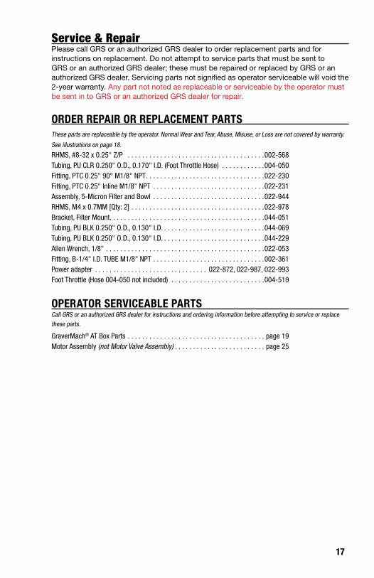
Service & RepairPlease call GRS or an authorized GRS dealer to order replacement parts and for instructions on replacement. Do not attempt to service parts that must be sent to GRS or an authorized GRS dealer; these must be repaired or replaced by GRS or an authorized GRS dealer. Servicing parts not signified as operator serviceable will void the 2-year warranty. Any part not noted as replaceable or serviceable by the operator must be sent in to GRS or an authorized GRS dealer for repair.
ORDER REPAIR OR REPLACEMENT PARTSThese parts are replaceable by the operator. Normal Wear and Tear, Abuse, Misuse, or Loss are not covered by warranty.
See illustrations on page 18.
RHMS, #8-32 x 0.25" Z/P . . . . . . . . . . . . . . . . . . . . . . . . . . . . . . . . . . . . . .002-568 Tubing, PU CLR 0.250" O.D., 0.170" I.D. (Foot Throttle Hose) . . . . . . . . . . . .004-050 Fitting, PTC 0.25" 90° M1/8" NPT . . . . . . . . . . . . . . . . . . . . . . . . . . . . . . . . .022-230Fitting, PTC 0.25" Inline M1/8" NPT . . . . . . . . . . . . . . . . . . . . . . . . . . . . . . .022-231Assembly, 5-Micron Filter and Bowl . . . . . . . . . . . . . . . . . . . . . . . . . . . . . . .022-944RHMS, M4 x 0.7MM [Qty: 2] . . . . . . . . . . . . . . . . . . . . . . . . . . . . . . . . . . . . .022-978Bracket, Filter Mount. . . . . . . . . . . . . . . . . . . . . . . . . . . . . . . . . . . . . . . . . . .044-051Tubing, PU BLK 0.250" O.D., 0.130" I.D. . . . . . . . . . . . . . . . . . . . . . . . . . . . .044-069Tubing, PU BLK 0.250" O.D., 0.130" I.D. . . . . . . . . . . . . . . . . . . . . . . . . . . . .044-229Allen Wrench, 1/8" . . . . . . . . . . . . . . . . . . . . . . . . . . . . . . . . . . . . . . . . . . . .022-053 Fitting, B-1/4" I.D. TUBE M1/8" NPT . . . . . . . . . . . . . . . . . . . . . . . . . . . . . . .002-361 Power adapter . . . . . . . . . . . . . . . . . . . . . . . . . . . . . . . 022-872, 022-987, 022-993 Foot Throttle (Hose 004-050 not included) . . . . . . . . . . . . . . . . . . . . . . . . . .004-519
OPERATOR SERVICEABLE PARTSCall GRS or an authorized GRS dealer for instructions and ordering information before attempting to service or replace these parts.
GraverMach® AT Box Parts . . . . . . . . . . . . . . . . . . . . . . . . . . . . . . . . . . . . . . page 19Motor Assembly (not Motor Valve Assembly) . . . . . . . . . . . . . . . . . . . . . . . . . page 25

18
004-050
022-872
022-993022-987
022-231
044-051
022-944
002-568
022-230
022-978
022-053002-361
044-069
044-229
004-519
Order Replacements:022-860 1 BOWL & COVER REPLACEMENT 022-861 1 FILTER REPLACEMENT
GraverMach® AT Accessories

19
044-181
002-109
022-964044-182
044-180
022-964
GraverMach® AT Box Parts ListPART NO. QTY. DESCRIPTION002-109 8 NUT, #10-32 HEX Z/P022-964 8 BHSCS, #10-32 x 0.38" BLK044-180 2 PLATE, GRAVERMACH® AT SIDE FRAME044-181 1 PLATE, GRAVERMACH® AT TOP FRAME044-182 2 BOX CORNER, GRAVERMACH® AT
Contact GRS or an authorized GRS dealer for replacement parts or repairs. Visit grs.com/dealers for dealers in your country.

20
Contact GRS or an authorized GRS dealer for replacement parts or repairs. Visit grs.com/dealers for dealers in your country.
GraverMach® AT Front Face Plate & Motor Valve Parts ListPART NO. QTY. DESCRIPTION002-110 4 WASHER, #8 FLAT Z/P002-309 8 HHSMS, #6 x .38" Z/P002-333 1 O-RING, 0.313" O.D., 0.188" I.D.002-443 2 BHCS, #6-32 x 0.25" BLK002-615 1 GAUGE, 1.63" O.D., 0-60 psi AIR002-766 6 CLAMP, WIRE, 0.25" O.D. TUBE002-971 1 PLUG, 0.190" O.D. x 0.125" SINTERED002-977 1 O-RING, 0.188" O.D., 0.063" I.D.004-966 1 VALVE, 4-WAY SWITCHING022-080 1 FITTING, B-0.17" I.D. TUBE M#10-32022-875 1 VALVE, PTC 0.25" NEEDLE022-966 1 FITTING, PTC 0.25" 90° F 1/8" NPT022-970 1 SWITCH, ILLUMINATED POWER022-980 1 REGULATOR, PRECISION AIR022-982 2 KNOB, GRAY 0.75"O.D., 0.25" I.D. x 0.69"023-019 1 GAUGE, 1.10" O.D. 0-30 psi AIR023-020 1 FITTING, PTC 0.25" 90° M #10-32023-021 4 FITTING, PTC 0.25" 90° M 1/8" NPT023-030 1 FITTING, B-Y 0.19" I.D. TUBE023-054 1 KNOB, B-G 1.25" O.D., 0.25" I.D. x 0.61"024-038 1 DECAL, GRAVERMACH® AT FRONT
PART NO. QTY. DESCRIPTION024-039 1 DECAL, GRAVERMACH® AT AIRTACT024-040 1 DECAL, GRAVERMACH® AT ON/OFF024-120 1 KNOB, B-G 0.75" O.D., 0.19" I.D. x 0.70"044-044 1 NEEDLE, VALVE044-065 1 TUBING, PU CLR 0.250" O.D., 0.170" I.D.044-065 1 TUBING, PU CLR 0.250" O.D., 0.170" I.D.044-067 1 TUBING, PU CLR 0.250" O.D., 0.170" I.D.044-112 1 TUBING, PU CLR 0.250" O.D., 0.170" I.D.044-177 1 PLATE, GRAVERMACH® AT FRONT FRAME044-185 1 VALVE BODY, AUXILIARY AIR044-186 1 BRACKET, 1.10" AIR GAUGE044-187 1 BRACKET, 1.63" AIR GAUGE044-224 1 TUBING, PU CLR 0.250" O.D., 0.170" I.D.044-225 1 TUBING, PU CLR 0.250" O.D., 0.170" I.D.044-225 1 TUBING, PU CLR 0.250" O.D., 0.170" I.D.044-226 1 TUBING, PU CLR 0.250" O.D., 0.170" I.D.044-226 1 TUBING, PU CLR 0.250" O.D., 0.170" I.D.044-230 1 TUBING, PU CLR 0.156" O.D., 0.094" I.D.044-500 1 WIRE, R-L-B-22 AWG POT F-SPADE044-501 1 WIRE, R-22 AWG F-SPADE T-RING044-501 1 WIRE, R-22 AWG F-SPADE T-RING044-502 1 WIRE, B-22 AWG F-SPADE T-RING
PART NO. QTY. DESCRIPTION004-951 1 VALVE BODY, ROTARY022-230 2 FITTING, PTC 0.25" 90° M1/8" NPT022-948 1 O-RING, 1.078" O.D., 0.938" I.D.022-977 1 FITTING, PTC 0.25" T M-1/8" NPT022-990 1 WASHER, 0.63" O.D., 0.41" I.D. x 0.03" NY044-006 1 VALVE SHROUD, ROTARY
GraverMach® AT Motor Valve Assembly

21
PART NO. QTY. DESCRIPTION002-110 4 WASHER, #8 FLAT Z/P002-309 8 HHSMS, #6 x .38" Z/P002-333 1 O-RING, 0.313" O.D., 0.188" I.D.002-443 2 BHCS, #6-32 x 0.25" BLK002-615 1 GAUGE, 1.63" O.D., 0-60 psi AIR002-766 6 CLAMP, WIRE, 0.25" O.D. TUBE002-971 1 PLUG, 0.190" O.D. x 0.125" SINTERED002-977 1 O-RING, 0.188" O.D., 0.063" I.D.004-966 1 VALVE, 4-WAY SWITCHING022-080 1 FITTING, B-0.17" I.D. TUBE M#10-32022-875 1 VALVE, PTC 0.25" NEEDLE022-966 1 FITTING, PTC 0.25" 90° F 1/8" NPT022-970 1 SWITCH, ILLUMINATED POWER022-980 1 REGULATOR, PRECISION AIR022-982 2 KNOB, GRAY 0.75"O.D., 0.25" I.D. x 0.69"023-019 1 GAUGE, 1.10" O.D. 0-30 psi AIR023-020 1 FITTING, PTC 0.25" 90° M #10-32023-021 4 FITTING, PTC 0.25" 90° M 1/8" NPT023-030 1 FITTING, B-Y 0.19" I.D. TUBE023-054 1 KNOB, B-G 1.25" O.D., 0.25" I.D. x 0.61"024-038 1 DECAL, GRAVERMACH® AT FRONT
PART NO. QTY. DESCRIPTION024-039 1 DECAL, GRAVERMACH® AT AIRTACT024-040 1 DECAL, GRAVERMACH® AT ON/OFF024-120 1 KNOB, B-G 0.75" O.D., 0.19" I.D. x 0.70"044-044 1 NEEDLE, VALVE044-065 1 TUBING, PU CLR 0.250" O.D., 0.170" I.D.044-065 1 TUBING, PU CLR 0.250" O.D., 0.170" I.D.044-067 1 TUBING, PU CLR 0.250" O.D., 0.170" I.D.044-112 1 TUBING, PU CLR 0.250" O.D., 0.170" I.D.044-177 1 PLATE, GRAVERMACH® AT FRONT FRAME044-185 1 VALVE BODY, AUXILIARY AIR044-186 1 BRACKET, 1.10" AIR GAUGE044-187 1 BRACKET, 1.63" AIR GAUGE044-224 1 TUBING, PU CLR 0.250" O.D., 0.170" I.D.044-225 1 TUBING, PU CLR 0.250" O.D., 0.170" I.D.044-225 1 TUBING, PU CLR 0.250" O.D., 0.170" I.D.044-226 1 TUBING, PU CLR 0.250" O.D., 0.170" I.D.044-226 1 TUBING, PU CLR 0.250" O.D., 0.170" I.D.044-230 1 TUBING, PU CLR 0.156" O.D., 0.094" I.D.044-500 1 WIRE, R-L-B-22 AWG POT F-SPADE044-501 1 WIRE, R-22 AWG F-SPADE T-RING044-501 1 WIRE, R-22 AWG F-SPADE T-RING044-502 1 WIRE, B-22 AWG F-SPADE T-RING
044-185002-977
023-020
044-044002-333
002-443
022-982
044-226
044-226
022-980
044-065
044-500
044-501
044-502
023-054
022-970
044-187
002-615
002-971
022-966
024-120
023-021
044-065
023-019
044-186
022-080
002-309
044-112
023-030
002-766
022-875
044-067
044-225
044-068
044-501 044-502044-500
004-966044-225
044-230
024-038
024-040
024-039
044-177
044-006
022-990
044-040
022-961
044-038
022-968
044-037
022-971
002-289
002-068
044-043
022-230
022-230
022-948
004-951
022-977
Motor Valve Assembly
PART NO. QTY. DESCRIPTION004-951 1 VALVE BODY, ROTARY022-230 2 FITTING, PTC 0.25" 90° M1/8" NPT022-948 1 O-RING, 1.078" O.D., 0.938" I.D.022-977 1 FITTING, PTC 0.25" T M-1/8" NPT022-990 1 WASHER, 0.63" O.D., 0.41" I.D. x 0.03" NY044-006 1 VALVE SHROUD, ROTARY
AT REGULATOR
SPOOL VALVE ORIFICE
MTR VALVE
AIRTACT CONTROL BLEED PORT
GROUND TO THE INSIDE
B-Y-R
RYB
REAR PLATE
TANK
TANK
SUPPLY
APPLY THREAD SEALANTLOCKTITE 545

22 GraverMach® AT Back Parts ListPART NO. QTY. DESCRIPTION002-062 2 RHMS, #8-32 x 0.50" Z/P002-092 2 TERMINAL, 22-16 AWG #10 RING002-104 2 NUT, #8-32 HEXKEP Z/P002-186 2 RIVET, 0.125" DIA. x 0.125" POP004-809 1 WIRE, B-22 AWG T-RING T-RING004-815 1 WIRE, R-22 AWG F-SPADE T-RING004-816 1 WIRE, B-22 AWG F-SPADE T-RING004-817 1 WIRE, R-22 AWG F-SPADE F-SPADE004-818 1 WIRE, B-22 AWG F-SPADE F-SPADE022-245 1 GROMMET, 0.50" O.D., 0.188" I.D. RUBBER022-962-R-PART 1 CONTROLLER, 24VDC PWM MOTOR022-965 3 FITTING, PTC 0.25" BULKHEAD023-032 1 FITTING, PTC 0.25" T024-036 1 VALVE, 24VDC SOLENOID
PART NO. QTY. DESCRIPTION024-041 1 DECAL, AUXILIARY OUTPUT024-042 1 FITTING, PTC 0.25" M#10-32024-118 2 NUT, #4-40 HEX Z/P024-119 2 RHMS, #4-40 x 0.63" Z/P044-059 1 DECAL, AIR INPUT/THROTTLE044-111 1 TUBING, PU BLK 0.250" O.D., 0.130" I.D.044-111 1 TUBING, PU BLK 0.250" O.D., 0.130" I.D.044-179 1 PLATE, GRAVERMACH® AT REAR FRAME044-189 1 SERIAL PLATE, GRAVERMACH® AT044-222 1 BRACKET, SOLENOID044-228 1 TUBING, PU BLK 0.250" O.D., 0.130" I.D.044-228 1 TUBING, PU BLK 0.250" O.D., 0.130" I.D.044-503 1 WIRE, B-R-22 AWG P-JCK F-SPD T-RLIT-294 1 DECAL, DRY AIR NOTICE
Contact GRS or an authorized GRS dealer for replacement parts or repairs. Visit grs.com/dealers for dealers in your country.

23
044-503
022-965
044-179
002-062
024-041
044-189
044-059
002-186
022-245
044-222
LIT-294
024-042
024-119
002-092
024-118
023-032
044-111
044-228044-228
044-111
004-817
004-818
004-816
004-815
002-104
B R
B R
RYB
004-809
PART NO. QTY. DESCRIPTION002-062 2 RHMS, #8-32 x 0.50" Z/P002-092 2 TERMINAL, 22-16 AWG #10 RING002-104 2 NUT, #8-32 HEXKEP Z/P002-186 2 RIVET, 0.125" DIA. x 0.125" POP004-809 1 WIRE, B-22 AWG T-RING T-RING004-815 1 WIRE, R-22 AWG F-SPADE T-RING004-816 1 WIRE, B-22 AWG F-SPADE T-RING004-817 1 WIRE, R-22 AWG F-SPADE F-SPADE004-818 1 WIRE, B-22 AWG F-SPADE F-SPADE022-245 1 GROMMET, 0.50" O.D., 0.188" I.D. RUBBER022-962-R-PART 1 CONTROLLER, 24VDC PWM MOTOR022-965 3 FITTING, PTC 0.25" BULKHEAD023-032 1 FITTING, PTC 0.25" T024-036 1 VALVE, 24VDC SOLENOID
PART NO. QTY. DESCRIPTION024-041 1 DECAL, AUXILIARY OUTPUT024-042 1 FITTING, PTC 0.25" M#10-32024-118 2 NUT, #4-40 HEX Z/P024-119 2 RHMS, #4-40 x 0.63" Z/P044-059 1 DECAL, AIR INPUT/THROTTLE044-111 1 TUBING, PU BLK 0.250" O.D., 0.130" I.D.044-111 1 TUBING, PU BLK 0.250" O.D., 0.130" I.D.044-179 1 PLATE, GRAVERMACH® AT REAR FRAME044-189 1 SERIAL PLATE, GRAVERMACH® AT044-222 1 BRACKET, SOLENOID044-228 1 TUBING, PU BLK 0.250" O.D., 0.130" I.D.044-228 1 TUBING, PU BLK 0.250" O.D., 0.130" I.D.044-503 1 WIRE, B-R-22 AWG P-JCK F-SPD T-RLIT-294 1 DECAL, DRY AIR NOTICE
MOTOR
POWER SWITCH
POWER REGULATOR
AT REGULATOR
REAR PLATE
RED 7.50"BLACK 5.50"
022-962-R-PART
RY B

24
022-230
022-381
002-536x 3
044-178
022-964X6
044-178
044-256
024-169
044-223
002-309X6
011-209X4
022-231X3
024-168X3
022-222X3
GraverMach® AT Base Parts ListPART NO. QTY. DESCRIPTION002-309 6 HHSMS, #6 x 0.38" Z/P002-536 3 NUT, 1/4"-20 FLNG LOCK Z/P011-209 4 FOOT, #8-32 x 0.50" RUBBER022-222 3 SOCKET HEAD CAP SCREW022-230 1 FITTING, PTC 0.25" 90° M1/8" NPT022-231 3 FITTING, PTC 0.25" INLINE M1/8" NPT022-381 1 PLUG, 1/8"-27 NPT x 0.25" PIPE022-964 6 BHSCS, #10-32 x 0.38" BLK024-168 3 SPECIAL WASHER024-169 1 O-RING044-178 1 PLATE, GRAVERMACH® AT BASE044-223 1 TUBING, PU CLR .250" O.D., 0.170" I.D.044-256 1 MOLDED AIR TANK (FOUR HOLE VERSION)
MOTOR VALVE

25
GraverMach® AT Base Parts ListPART NO. QTY. DESCRIPTION002-309 6 HHSMS, #6 x 0.38" Z/P002-536 3 NUT, 1/4"-20 FLNG LOCK Z/P011-209 4 FOOT, #8-32 x 0.50" RUBBER022-222 3 SOCKET HEAD CAP SCREW022-230 1 FITTING, PTC 0.25" 90° M1/8" NPT022-231 3 FITTING, PTC 0.25" INLINE M1/8" NPT022-381 1 PLUG, 1/8"-27 NPT x 0.25" PIPE022-964 6 BHSCS, #10-32 x 0.38" BLK024-168 3 SPECIAL WASHER024-169 1 O-RING044-178 1 PLATE, GRAVERMACH® AT BASE044-223 1 TUBING, PU CLR .250" O.D., 0.170" I.D.044-256 1 MOLDED AIR TANK (FOUR HOLE VERSION)
044-103
023-023
044-105023-025
044-102
044-101
022-081
002-950
044-188
022-057
002-590
023-107
044-264
022-029
002-766
Spool Assembly
GraverMach® AT Spool Assembly GraverMach® AT Motor Assembly
The Spool Assembly is NOT OPERATOR SERVICEABLE. This part is factory set to this
particular system. Repair or replacement requires return of engraving system to GRS
or an authorized GRS dealer.
The Motor Assembly is operator
replaceable. Contact GRS or an authorized
GRS dealer for details.
Motor Assembly
#004-969
SIMILAR TO:
LIMITS EXCEPTAS SHOWN
ANGLE ± 0.5 °.XXX ± 0.010".XX ± 0.030"FRAC ± .0.030"
DO NOT SCALE
GLENDO CORPORATIONEMPORIA, KANSAS 66801
FINISHN/A
SPEC.
HEAT TREAT
SPEC.
NAME
MOTOR ROTOR KITMATERIAL
DRAWN
CHK'D
APPV'D
LCTDATE
11/30/12DATE
DATE
N/ASPEC.
N/ASCALE
1:1REV.
004-969NUMBER
-
NOTES:
004-969
-
N/A
N/A
N/A
Contact GRS or an authorized GRS dealer for replacement parts or repairs. Visit grs.com/dealers for dealers in your country.

26
044-500
022-961
022-970
044-501
044-501
044-502 004-809
004-816
004-817
004-818
022-962
004-815
GraverMach® AT Wiring Diagram
24 VDC MOTOR
24 VDC MOTORCONTROL
Wire, R-L-B-22AWG POT F-Spade (VIEWED FROM BACK)
BLACK
YELLOW
RED
SWITCH, ILLUMINATED POWER(VIEWED FROM THE BACK)
PWM MOTOR CONTROL BOARD
24 VDC MOTOR
27
044-225
044-230
044-225
044-224
044-112
044-065
044-226
044-227
044-226
044-065
044-228
044-111
044-228 044-111
044-223
044-234
044-067
044-068
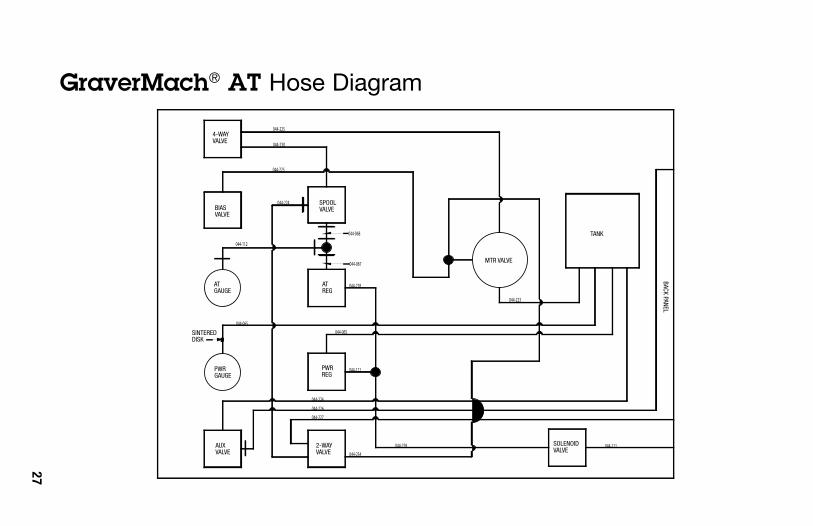
GraverMach® AT Hose Diagram
MTR VALVE
BACK PANEL
TANK
SOLENOID VALVE
2-WAYVALVE
AUXVALVE
PWR REG
AT REG
SPOOLVALVE
4-WAYVALVE
BIASVALVE
ATGAUGE
SINTEREDDISK
PWRGAUGE

28
WARRANTY Each GraverMach® AT, including provided foot throttle, carries a full 2-year warranty covering parts and labor. Contact GRS or an authorized GRS dealer before returning any equipment.
These products are designed for reliable operation using most sources of compressed air. However, some air supplies contain excessive water, oil, dirt, rust, or other contaminants. The built-in filter of the engraving system is a final filter to protect against normal dirt and water. If the compressed air has excessive contaminants, install the necessary filter(s) and water trap(s) ahead of the engraving system.
Oil contamination can be gradual and subtle. If an oil residue (usually yellow or brown, sticky or liquid) becomes present in the filter bowl of the engraving system, or in the handpiece / throttle hose, the compressed air most likely contains oil or contaminants. Older oil lubricated and “silent” compressors that use internal oil are more likely to cause oil contamination. If this occurs, install a Coalescing Oil Filter (GRS #004-579 or equivalent).
NOTE: Damage caused by contaminated compressed air is not covered by the warranty.
GraverMach® AT, GraverMach®, GraverMax® G8, GraverMax® SC, GraverMax®, GraverMate®, GraverSmith®, BenchMate™, and Power Hone™ are trademarks of Glendo Corporation. Covered by USA and foreign patents. Printed in USA. Products made in USA.
© 2009–2014 Glendo Corporation. All rights reserved.
LIT-320 Last Update: October 1, 2013
Glendo Corporation900 Overlander RoadEmporia, KS 66801 USA
Phone: +1-620-343-1084Fax: +1-620-343-9640 E-mail: [email protected]