
Granville-Phillips Mini-Convectron Module with RS-485 ... · PDF fileGranville-Phillips®...
50
Granville-Phillips ® Mini-Convectron ® Module with RS-485 Interface Instruction Manual Instruction manual part number 275955 Revision F - November 2016 Series 275
Transcript of Granville-Phillips Mini-Convectron Module with RS-485 ... · PDF fileGranville-Phillips®...

Granville-Phillips® Mini-Convectron® Module with RS-485 Interface
Instruction Manual
Instruction manual part number 275955
Revision F - November 2016
Series 275

Granville-Phillips® Mini-Convectron® Module with RS-485 Interface
Series 275
Instruction Manual
Customer Service / Technical Support:
MKS Pressure and Vacuum Measurement SolutionsMKS Instruments, Inc., Granville-Phillips® Division6450 Dry Creek ParkwayLongmont, Colorado 80503 USATel: 303-652-4400Fax: 303-652-2844Email: [email protected]
MKS Corporate HeadquartersMKS Instruments, Inc.2 Tech Drive, Suite 201Andover, MA 01810 USATel: 978-645-5500Fax: 978-557-5100Email: [email protected]
© 2016 MKS Instruments, Inc. All rights reserved.Granville-Phillips® and Convectron® are registered trademarks, and mksinstTM is a trademark of MKS Instruments, Inc. All other trademarks and registered trademarks are the properties of their respective owners.
This instruction manual is for use only with the following catalog numbers:
Catalog numbers for Series 275 Mini-Convectron Moduleswith RS-485 Interface
Mini-Convectron Module with: Catalog #1/8 NPT / 1/2 inch tubulation 2759441/4 inch VCR-type female fitting 2759451/2 inch VCR-type female fitting 2759463/8 inch VCO-type male fitting 2759471.33 inch (NW16CF) ConFlat-type flange 2759482.75 inch (NW35CF) ConFlat-type flange 275949NW10KF flange 275950NW16KF flange 275951NW25KF flange 275952NW40KF flange 275953NW50KF flange 275954
VCR & VCO are registered trademarks of Swagelok Company.
Instruction Manual

Mini-Convectron Module with RS-485 5Instruction Manual - 275955
Table of Contents
Chapter 1 Safety and Introduction . . . . . . . . . . . . . . . . . . . . . . . . . . . . . . . . . . . 71.1 Safety Introduction . . . . . . . . . . . . . . . . . . . . . . . . . . . . . . . 71.2 Reading and Following Instructions . . . . . . . . . . . . . . . . . . 81.3 Explosion / Implosion . . . . . . . . . . . . . . . . . . . . . . . . . . . . . 91.4 System Grounding . . . . . . . . . . . . . . . . . . . . . . . . . . . . . . . 111.5 Operation . . . . . . . . . . . . . . . . . . . . . . . . . . . . . . . . . . . . . . 111.6 Service Guidelines . . . . . . . . . . . . . . . . . . . . . . . . . . . . . . . 111.7 Receiving Inspection . . . . . . . . . . . . . . . . . . . . . . . . . . . . . . 12
Domestic Shipments . . . . . . . . . . . . . . . . . . . . . . . . . . . . . . 12International Shipments . . . . . . . . . . . . . . . . . . . . . . . . . . . 12Damaged Material . . . . . . . . . . . . . . . . . . . . . . . . . . . . . . . 12
1.8 Specifications . . . . . . . . . . . . . . . . . . . . . . . . . . . . . . . . . . . 13
Chapter 2 Installation . . . . . . . . . . . . . . . . . . . . . . . . . . . . . . . . . . . . . . . . . . . 152.1 Important Precautions for Mini-Convectron Installation . . . 152.2 Mounting Location and Orientation . . . . . . . . . . . . . . . . . . 16
Location . . . . . . . . . . . . . . . . . . . . . . . . . . . . . . . . . . . . . . . 17Environment . . . . . . . . . . . . . . . . . . . . . . . . . . . . . . . . . . . . 17
2.3 Grounding . . . . . . . . . . . . . . . . . . . . . . . . . . . . . . . . . . . . . 172.4 Dimensions . . . . . . . . . . . . . . . . . . . . . . . . . . . . . . . . . . . . . 18
Compression Mount/Quick Connect . . . . . . . . . . . . . . . . . . 191/8 NPT Mount . . . . . . . . . . . . . . . . . . . . . . . . . . . . . . . . . . 19NW or Flange Mount . . . . . . . . . . . . . . . . . . . . . . . . . . . . . 19ConFlat Flange . . . . . . . . . . . . . . . . . . . . . . . . . . . . . . . . . . 19
2.5 I/O Connector Wiring . . . . . . . . . . . . . . . . . . . . . . . . . . . . . 192.6 RS-485 Network Wiring . . . . . . . . . . . . . . . . . . . . . . . . . . . 20
Chapter 3 Operation . . . . . . . . . . . . . . . . . . . . . . . . . . . . . . . . . . . . . . . . . . . . 213.1 Theory of Operation . . . . . . . . . . . . . . . . . . . . . . . . . . . . . . 213.2 Front Panel Features . . . . . . . . . . . . . . . . . . . . . . . . . . . . . . 223.3 Digital Communications . . . . . . . . . . . . . . . . . . . . . . . . . . . 23
Syntax/Address Overview . . . . . . . . . . . . . . . . . . . . . . . . . . 23RS-485 Address Switch Settings . . . . . . . . . . . . . . . . . . . . . 23Baud Rate, Stop Bit and Parity . . . . . . . . . . . . . . . . . . . . . . . 23Command Set . . . . . . . . . . . . . . . . . . . . . . . . . . . . . . . . . . . 24Interface Default Settings . . . . . . . . . . . . . . . . . . . . . . . . . . 24ReaD Convectron pressure response . . . . . . . . . . . . . . . . . . 25Set Offset Address . . . . . . . . . . . . . . . . . . . . . . . . . . . . . . . . 25Set span (typically at atmospheric pressure) . . . . . . . . . . . . 26Set zero (at or near vacuum) . . . . . . . . . . . . . . . . . . . . . . . . 27Set factory default . . . . . . . . . . . . . . . . . . . . . . . . . . . . . . . . 28Set baud rate . . . . . . . . . . . . . . . . . . . . . . . . . . . . . . . . . . . . 28Set parity to 8 bits, none . . . . . . . . . . . . . . . . . . . . . . . . . . . 28Set parity to 7 bits, odd . . . . . . . . . . . . . . . . . . . . . . . . . . . . 28

6 Mini-Convectron Module with RS-485Instruction Manual - 275955
Set parity to 7 bits, even . . . . . . . . . . . . . . . . . . . . . . . . . . . 29Set frequency . . . . . . . . . . . . . . . . . . . . . . . . . . . . . . . . . . . 29Reset module . . . . . . . . . . . . . . . . . . . . . . . . . . . . . . . . . . . 29RX, TX Timing . . . . . . . . . . . . . . . . . . . . . . . . . . . . . . . . . . . 30
Chapter 4 Calibration . . . . . . . . . . . . . . . . . . . . . . . . . . . . . . . . . . . . . . . . . . . 314.1 Calibration . . . . . . . . . . . . . . . . . . . . . . . . . . . . . . . . . . . . . 31
Vacuum Adjustment . . . . . . . . . . . . . . . . . . . . . . . . . . . . . . 31Atmosphere Adjustment . . . . . . . . . . . . . . . . . . . . . . . . . . . 31
4.2 Use with Gases other than N2 and Air . . . . . . . . . . . . . . . . . 32
Chapter 5 Service/Maintenance . . . . . . . . . . . . . . . . . . . . . . . . . . . . . . . . . . . . 415.1 Service Guidelines . . . . . . . . . . . . . . . . . . . . . . . . . . . . . . . 415.2 Mini-Convectron Disassembly . . . . . . . . . . . . . . . . . . . . . . 415.3 Troubleshooting . . . . . . . . . . . . . . . . . . . . . . . . . . . . . . . . . 42
Reset the Module to Factory Defaults . . . . . . . . . . . . . . . . . 435.4 Convectron Gauge Bakeout Instructions . . . . . . . . . . . . . . . 445.5 Cleaning a Convectron Gauge . . . . . . . . . . . . . . . . . . . . . . 445.6 Returning a Mini-Convectron Module for Service . . . . . . . . 45

Mini-Convectron Module with RS-485 7Instruction Manual - 275955
Chapter 1 Safety and Introduction
1.1 Safety Introduction START BY READING THESE IMPORTANT SAFETY INSTRUCTIONS AND NOTES collected here for your convenience and repeated with additional information at appropriate points in these instructions.
NOTE: These instructions do not and cannot provide for every contingency that may arise in connection with the installation, operation, or maintenance of this product. If you require further assistance, contact MKS, Granville-Phillips Division at the address on the title page of this manual.
This product was designed and tested to offer reasonably safe service provided it is installed, operated, and serviced in strict accordance with these safety instructions.
In these instructions the word “product” refers to the Mini-Convectron Module and all of its approved parts and accessories.
The instructions in this User Manual explain how to install, operate, and maintain the Granville-Phillips® Mini-Convectron® vacuum gauge module.
• This chapter explains the caution and warning statements used throughout the manual which must be adhered to at all times, your responsibility to read and follow all instructions, how to contact customer service, and product specifications.
• Chapter 2 explains how to install and connect the module.
These safety alert symbols in this manual or on the Product rear panel, mean caution − personal safety, property damage or danger from electric shock. Read these instructions carefully.
Failure to comply with these instructions may result in serious personal injury, including death, or property damage.
Table 1-1 Terms Describing the Mini-Convectron Module and Components
Term Description
Module The Mini-Convectron vacuum gauge module, which contains a Convectron convection-enhanced Pirani heat-loss pressure gauge.
Convectron Gauge The Convectron convection-enhanced Pirani heat-loss gauge, which measures pressure within the vacuum chamber.

Chapter 1
8 Mini-Convectron Module with RS-485Instruction Manual - 275955
• Chapter 3 explains the theory of operation, how to operate the module, and the RS-485 Interface commands.
• Chapter 4 explains calibration and using the module with gases other than N2 or Air.
• Chapter 5 explains troubleshooting, Convectron gauge testing, removal and replacement, and module return-for-repair procedures.
1.2 Reading and Following Instructions
You must comply with all instructions while you are installing, operating, or maintaining the module. Failure to comply with the instructions violates standards of design, manufacture, and intended use of the module. MKS Instruments, Inc. disclaims all liability for the customer's failure to comply with the instructions.
• Read instructions – Read all instructions before installing or operating the product.
• Follow instructions – Follow all installation, operating and maintenance instructions.
• Retain instructions – Retain the instructions for future reference.
• Heed warnings and cautions – Adhere to all warnings and caution statements on the product and in these instructions.
Parts and accessories – Install only those replacement parts and accessories that are recommended by Granville-Phillips. Substitution of parts is hazardous.
caution
Caution statements alert you to hazards or unsafe practices that could result in minor personal injury or property damage.Each caution statement explains what you must do to prevent or avoid the potential result of the specified hazard or unsafe practice.
warning
Warning statements alert you to hazards or unsafe practices that could result in severe property damage or personal injury due to electrical shock, fire, or explosion.
Each warning statement explains what you must do to prevent or avoid the potential result of the specified hazard or unsafe practice.

Safety and Introduction
Mini-Convectron Module with RS-485 9Instruction Manual - 275955
Safety and Introduction
Caution and warning statements comply with American Institute of Standards Z535.1–2002 through Z535.5–2002, which set forth voluntary practices regarding the content and appearance of safety signs, symbols, and labels.
Each caution or warning statement explains:
a. The specific hazard that you must prevent or unsafe practice that you must avoid,
b. The potential result of your failure to prevent the specified hazard or avoid the unsafe practice, and
c. What you must do to prevent the specified hazardous result.
1.3 Explosion / Implosion
warning
The fumes from solvents such as trichloroethylene, perchloroethylene, toluene, and acetone can be dangerous to health if inhaled. Use only in well ventilated areas exhausted to the outdoors. Acetone and toluene are highly flammable and should not be used near an open flame or energized electrical equipment.
warning
If used improperly, Mini−Convectron Gauges can supply misleading pressure indications that can result in dangerous overpressure conditions within the system.Do not operate in an explosive atmosphere.Do not operate the product in the presence of flammable gases or fumes. Operation of any electrical instrument in such an environment constitutes a definite safety hazard. Do not use the product to measure the pressure of explosive or combustible gases or gas mixtures. The sensor wire of the Mini−Convectron Gauge normally operates at only 125 ˚C, but it is possible that Controller malfunction can raise the sensor temperature above the ignition temperature of combustible mixtures. Danger of explosion or inadvertent venting to atmosphere exists on all vacuum systems which incorporate gas sources or involve processes capable of pressurizing the system above safe limits.

Chapter 1
10 Mini-Convectron Module with RS-485Instruction Manual - 275955
Danger of injury to personnel and damage to equipment exists on all vacuum systems that incorporate gas sources or involve processes capable of pressuring the system above the limits it can safely withstand.
For example, danger of explosion in a vacuum system exists during backfilling from pressurized gas cylinders because many vacuum devices such as ionization gauge tubes, glass windows, glass belljars, etc., are not designed to be pressurized.
Series 275 instruments are furnished calibrated for N2. They also measure the pressure of air correctly within the accuracy of the instrument. Do not attempt to use a Series 275 Gauge calibrated for N2 to measure or control the pressure of other gases such as argon or CO2, unless accurate conversion data for N2 to the other gas is properly used. See Use with Gases other than N2 and Air beginning on page 32.
A pressure relief valve should be installed in the system if the possibility of exceeding 1000 Torr (1333 mbar) exists.
Suppliers of pressure relief valves and pressure relief disks can be located via an online search, and are listed at ThomasNet.com under “Relief Valves”. Confirm that these safety devices are properly installed before installing the product.
In addition, check that (1) the proper gas cylinders are installed, (2) gas cylinder valve positions are correct on manual systems, and (3) the automation is correct on automated systems.
warning
If accurate conversion data is not used, or is improperly used, a potential overpressure explosion hazard can be created under certain conditions. Using the N2 calibration to pressurize a vacuum system above about 1 Torr with certain other gases can cause dangerously high pressures which may cause explosion of the system. See Chapter 4, Calibration, before using the Mini−Convectron vacuum gaugewith other gases.

Safety and Introduction
Mini-Convectron Module with RS-485 11Instruction Manual - 275955
Safety and Introduction
1.4 System Grounding Grounding, though simple, is very important! Be certain that ground circuits are correctly used on your ion gauge power supplies, gauges, and vacuum chambers, regardless of their manufacturer. Safe operation of vacuum equipment, including the Mini-Convectron Module, requires grounding of all exposed conductors of the gauges, the controller and the vacuum system. Lethal Voltages may be established under some operating conditions unless correct grounding is provided.
Ion producing equipment, such as ionization gauges, mass spectrometers, sputtering systems, etc., from many manufacturers may, under some conditions, provide sufficient electrical conduction via a plasma to couple a high voltage electrode potential to the vacuum chamber. If exposed conductive parts of the gauge, controller, and chamber are not properly grounded, they may attain a potential near that of the high voltage electrode during this coupling. Potential fatal electrical shock could then occur because of the high voltage between these exposed conductors and ground.
1.5 Operation It is the installer's responsibility to ensure that the automatic signals provided by the process control module are always used in a safe manner.
Carefully check manual operation of the system and the setpoint programming before switching to automatic operation. Where an equipment malfunction could cause a hazardous situation, always provide for fail-safe operation. As an example, in an automatic backfill operation where a malfunction might cause high internal pressures, provide an appropriate pressure relief device.
1.6 Service Guidelines Some minor problems are readily corrected on site. If the product requires service, contact the MKS, Granville-Phillips Division Technical Support Department at 1-303-652-4400 or 1-800-776-6543 for troubleshooting help over the phone.
If the product must be returned to the factory for service, request a Return Material Authorization (RMA) from Granville-Phillips. Do not return products without first obtaining an RMA. In some cases a hazardous materials disclosure form may be required. The MKS/Granville-Phillips Customer Service Representative will advise you if the hazardous materials document is required.
When returning products to Granville-Phillips, be sure to package the products to prevent shipping damage. Shipping damage on returned products as a result of inadequate packaging is the Buyer's responsibility.

Chapter 1
12 Mini-Convectron Module with RS-485Instruction Manual - 275955
For Customer Service / Technical Support:
MKS Pressure and Vacuum Measurement SolutionsMKS Instruments, Inc., Granville-Phillips® Division6450 Dry Creek ParkwayLongmont, Colorado 80503 USATel: 303-652-4400Fax: 303-652-2844Email: [email protected]
MKS Corporate HeadquartersMKS Instruments, Inc.2 Tech Drive, Suite 201Andover, MA 01810 USATel: 978-645-5500Fax: 978-557-5100Email: [email protected].
1.7 Receiving Inspection
Domestic Shipments Inspect all material received for shipping damage.
Confirm that your shipment includes all material and options ordered. If materials are missing or damaged, the carrier that made the delivery must be notified within 15 days of delivery in accordance with Interstate Commerce regulations in order to file a valid claim with the carrier. Any damaged material including all containers and packing should be held for carrier inspection. Contact our Customer Service Department, 6450 Dry Creek Parkway, Longmont, Colorado 80503 USA (telephone 303-652-4400) if your shipment is not correct for reasons other than shipping damage.
International Shipments
Inspect all material received for shipping damage. Confirm that your shipment includes all material and options ordered. If items are missing or damaged the carrier making delivery to the customs broker must be notified within 15 days of delivery.
If an airfreight forwarder handles the shipment and their agent delivers the shipment to customs the claim must be filed with the airfreight forwarder.
If an airfreight forwarder delivers the shipment to a specific airline and the airline delivers the shipment to customs the claim must be filed with the airline, not the freight forwarder.

Safety and Introduction
Mini-Convectron Module with RS-485 13Instruction Manual - 275955
Safety and Introduction
Damaged Material Any damaged material, including all containers and packaging, should be held for carrier inspection. Contact our Customer Service Department, 6450 Dry Creek Parkway, Longmont, Colorado 80503, USA (telephone 303-652-4400) if your shipment is not correct for reasons other than shipping damage.
1.8 Specifications
Pressure Measurement
Measurement Range for Air or N2 Torr 1 x 10⁻⁴ to 1000mbar 1 x 10⁻⁴ to 1333Pascal 1 x 10⁻² to 1.33 x 10⁵
Resolution Torr 1 x 10⁻⁴
mbar 1 x 10⁻⁴
Pascal 1 x 10⁻²
Measurements will change with different gases and mixtures. Do not use the module with flammable or explosive gases. The module is factory calibrated for use with Air or N2. It measures the pressure of air correctly within the specified accuracy of the instrument. If the module will measure the pressure of a gas other than Air or N2, you must calibrate the Mini-Convectron Module for the process gas. See Use with Gases other than N2 and Air on page-32 in the Calibration Chapter.
To achieve accurate readings down to 1 x 10⁻⁴ Torr, periodic calibration at below 1 x 10⁻⁵ Torr must be performed.
Temperature Limits
Operating Temperature +4 to +40 °C (+32 to +104 °F) ambient, non-condensing
Non-operating Temperature –40 to +70 °C (–40 to +158 °F)
Bakeout Temperature Range +85 °C maximum with electronics attached
+150 °C maximum with electronics removed
Power Requirements and Electrical Connections
Power Requirement 11.0 to 16.0 Vdc, 0.12 AMust be protected against reversals, transients, or over-voltages.
I/O Connector 8-pin DIN type

14 Mini-Convectron Module with RS-485Instruction Manual - 275955
Convectron Gauge
Sensing Wire Filament Gold-plated tungsten (standard)
Internal Volume 40 cc (2.5 cu in.)
Materials Exposed to Vacuum 304 stainless steel, gold, borosilicate glass, kovar, alumina, NiFe alloy, polyimide
Digital Interface
RS-485 2-wire or 4-wire
Baud Rate 300 baud to 38.4 Kbaud
Data Format 7-bits, even parity, 1 stop bit
7-bits, odd parity, 1 stop bit
8-bits, no parity, 1 stop bit

Mini-Convectron Module with RS-485 15Instruction Manual - 275955
Chapter 2 Installation
2.1 Important Precautions for Mini-Convectron Installation
The following precautions in the use and installation of the Mini-Convectron must be observed.
• It is recommended that the Mini-Convectron be installed with the port oriented vertically downward to ensure that no system condensates or other liquids collect in the gauge tube. The gauge tube axis must be horizontal if it is to be used at pressures above 1 Torr. Although the gauge tube will read correctly below 1 Torr when mounted in any position, erroneous readings will result at pressures above 1 Torr if the tube axis is not horizontal.
• Do not use a compression mount (quick connect) for attaching the Mini-Convectron to the system in applications resulting in positive pressures in the gauge tube. Positive pressures might blow the tube out of a compression fitting and damage equipment and injure personnel. Pipe thread or flange mounting systems should be used for positive pressure applications. In any case, the absolute pressure in the Convectron gauge tube should not exceed 1000 Torr.
• Do not mount the Mini-Convectron so that deposition of process vapors, upon the internal surfaces of the gauge tube, may occur through line-of-sight access to the interior of the gauge tube.
• Do not install the Mini-Convectron where high amplitudes of vibration are present. Excessive vibration will cause forced convection at high pressure giving erroneous readings.
• Do not install the gauge tubes where they will be subject to corrosive gases such as mercury vapor or fluorine which will attack the gold plated sensor.
• For greatest accuracy and repeatability the Mini-Convectron Module should be located in a stable room temperature environment.
• All connections to the Mini-Convectron Module are to be made with shielded cable. The shield or shields are to be connected to the connector shell.

Chapter 2
16 Mini-Convectron Module with RS-485Instruction Manual - 275955
2.2 Mounting Location and Orientation
• Cleanliness pays. Keep the port cover in place until just before installation.
• For proper operation above about 1 Torr, install Mini-Convectron Modules with the gauge axis horizontal (see Figure 2-1). Although the gauge will read correctly below 1 Torr when mounted in any position, erroneous readings will result at pressures above 1 Torr if the gauge axis is not horizontal.
• Vibration causes convection cooling of the sensor and will result in high pressure readings. Mount Mini-Convectron Modules where they will not vibrate excessively.
• Orient the gauge to prevent condensation of process vapors on the internal surfaces through line-of-sight access to its interior. If vapor condensation is likely, orient the port downward to help liquids drain out.
Figure 2-1 Mini-Convectron Module Installation

Installation
Mini-Convectron Module with RS-485 17Instruction Manual - 275955
Location Where you mount the Mini-Convectron Module is critical to obtaining reliable pressure measurements. Long tubing or other constrictions can cause large errors in pressure readings. If you mount the gauge near the pump, the pressure in the gauge may be considerably lower than in the rest of the system. If you place the gauge near a gas inlet or other source of contamination, the pressure in the gauge may be much higher than in the rest of the system.
Environment To minimize temperature effects, locate pressure gauges away from internal and external heat sources, in an area where the ambient temperature is reasonably constant.
2.3 Grounding
Under certain conditions, dangerously high voltage can be conducted through a gas directly to an ungrounded conductor almost as effectively as through a copper wire. The ability of an electric current to flow through a gas under certain circumstances poses a serious risk. Do not touch the exposed pins on any gauge installed on a vacuum system when high voltage is present.
The Convectron Gauge envelope may not be reliably grounded through its vacuum connection. For safety, you must either add a separate ground wire, or shield the envelope to prevent human contact.
Ground the gauge envelope by using a metal hose clamp on the gauge connected by a #12 AWG (minimum size) copper wire to the grounded vacuum chamber.
Figure 2-2 Grounding the Mini-Convectron Gauge
When high voltage is present, all exposed conductors of a vacuum system must be maintained at Earth ground.
#12 AWG copper wire
Chapter 2
18 Mini-Convectron Module with RS-485Instruction Manual - 275955
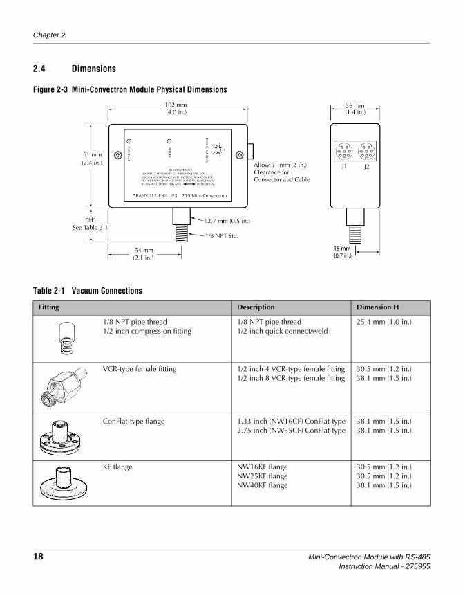
2.4 Dimensions
Figure 2-3 Mini-Convectron Module Physical Dimensions
Table 2-1 Vacuum Connections
Fitting Description Dimension H
1/8 NPT pipe thread1/2 inch compression fitting
1/8 NPT pipe thread1/2 inch quick connect/weld
25.4 mm (1.0 in.)
VCR-type female fitting 1/2 inch 4 VCR-type female fitting1/2 inch 8 VCR-type female fitting
30.5 mm (1.2 in.)38.1 mm (1.5 in.)
ConFlat-type flange 1.33 inch (NW16CF) ConFlat-type2.75 inch (NW35CF) ConFlat-type
38.1 mm (1.5 in.)38.1 mm (1.5 in.)
KF flange NW16KF flangeNW25KF flangeNW40KF flange
30.5 mm (1.2 in.)30.5 mm (1.2 in.)38.1 mm (1.5 in.)

Installation
Mini-Convectron Module with RS-485 19Instruction Manual - 275955
Compression Mount/Quick Connect
Do not use for positive pressure applications. The gauge may be forcefully ejected. The gauge port is designed to fit a standard 1/2 in. compression/quick connect mounting such as an Ultra-Torr fitting. Insert the gauge tube port into the compression fitting and finger-tighten the compression ring. A light film of vacuum grease, such as Apiezon®, will ensure sealing.
1/8 NPT Mount Fits standard 1/8 NPT female fitting. Wrap the threads of the gauge port with thread seal tape and hand tighten. Do not use a wrench or tool. Tighten only enough to achieve a seal.
NW or Flange Mount The KF mounting system requires O-rings and centering rings between mating flanges. Tightening the wing nut will hold the flanges and the aluminum flange clamp together. Maximum pressure for this style of mounting system is 1000 Torr absolute.
ConFlat Flange To minimize the possibility of leaks with ConFlat® flanges, use high strength stainless steel bolts and a new, clean OFHC copper gasket. Avoid scratching the seal surfaces. To avoid contamination, do not use nonmetal gaskets.
Finger tighten all bolts. Use a wrench to continue tightening 1/8 turn at a time in crisscross order, e.g., 1, 4, 2, 5, 3, 6, 4 until all flanges are in contact. After contact, further tighten each bolt about 1/16 turn.
2.5 I/O Connector Wiring The DIN type connector has the pin assignments shown below.
Figure 2-4 Power and I/O Connectors

Chapter 2
20 Mini-Convectron Module with RS-485Instruction Manual - 275955
2.6 RS-485 Network Wiring
Connection between multiple controllers can easily be made by daisy chaining gauge controllers together with the signal from the host computer going into one connector then out the other to another gauge controller.
• The maximum total cable length is 4,000 ft.
• No more than 32 devices can be connected to one RS-485 communications line.
When an RS-485 network is in an idle state, all nodes are in listen (receive) mode. Under this condition there are no active drivers on the network. To maintain the proper idle voltage state, bias resistors must be applied at the ends of the lines to force the data lines to the idle condition. Figure 2-5 illustrates the placement of bias resistors on a host computer for typical 5 volt and 24 volt systems.
Figure 2-5 Bias Resistor Placement on Host Controller

Mini-Convectron Module with RS-485 21Instruction Manual - 275955
Chapter 3 Operation
3.1 Theory of Operation The module measures gas pressures from 1 x 10⁻⁴ Torr to 1000 Torr. Vacuum chamber pressure is measured by a Convectron (convection-enhanced) Pirani heat-loss gauge.
The Convectron gauge operates like a standard Pirani gauge, which employs the principle of a Wheatstone bridge to convert pressure to voltage, but uses convection cooling to enable accurate pressure measurement, when properly calibrated, from 10–4 to 1000 Torr.
The sensing wire is an ultra-fine strand of gold-plated tungsten or solid platinum. The heated sensing wire loses more heat as the ambient gas pressure increases. The more molecules contact the sensing wire, the more power is required to keep the sensing wire at a constant temperature. So, as pressure increases, the voltage across the Wheatstone bridge also increases.
The Convectron gauge has a temperature compensator, which causes bridge voltage to remain unaffected by changes in ambient temperature.
Figure 3-1 is a diagram of the module controller. The Convectron gauge sensing wire is designated R1 in the Wheatstone bridge circuit. The temperature compensator is designated R2. At bridge null, the following equation applies:
Bridge voltage is a non-linear function of pressure. This relationship is illustrated in Figure 3-1. If the ambient temperature does not change, R1 remains constant.
Figure 3-1 Wheatstone Bridge Diagram
R1R2 R3+
R4--------------------=

Chapter 3
22 Mini-Convectron Module with RS-485Instruction Manual - 275955
As vacuum chamber pressure decreases, the number of molecules in the vacuum chamber and the resulting heat loss from the sensing wire also decrease. Temperature and R1 resistance therefore increase.
The increased resistance through R1 causes the bridge to become unbalanced and a voltage to develop across the null terminals. The bridge controller senses the null voltage and decreases the voltage across the bridge until the null voltage again equals zero. When the bridge voltage decreases, the power dissipation in the sensing wire decreases, causing R1 resistance to decrease to its previous value.
A pressure increase causes an opposing series of occurrences, during which the bridge controller increases the bridge voltage to maintain a zero null voltage.
3.2 Front Panel Features
Figure 3-2 Front Panel Indicators and Address Selector
Table 3-1 Front Panel Features
Front panel feature Function
P > 100 mTorr Indicator A red light emitting diode is used as a rough pressure indicator. The LED will be OFF below 100 milliTorr and gradually turn on as pressure increases.
Power Indicator A green light emitting diode is on when power is applied and the microprocessor is working. The LED blinks if the microprocessor is not working. The LED is OFF when no power applied.
Address Selector Rotate the pointer to the desired RS-485 address. The address switch value is added to the programmed offset address (SA command).

Operation
Mini-Convectron Module with RS-485 23Instruction Manual - 275955
Operlation
3.3 Digital Communications
Syntax/Address Overview
A command from the host must include a start character, address, data, and terminator:
(start character)(address)(data)(terminator)
• The start character is "#"
• The address is two ASCII digits representing the Hex address of the module. Example: 0F is address 15
• The data field is explained in the command descriptions. All command examples are shown with an address of 01. If the address is changed, both the command and response will have the new address instead of 01. All alpha characters can be upper or lower case. The response is in upper case.
• The terminator character is “control” M or Hex 0D for a carriage return “CR”, and “_” space signified below by:
__ = spaceCR = carriage return.
All data fields responses will contain 13 characters, uppercase alpha characters. The commands are of various character lengths
A response of ?01_SYNTX_ER CR is caused by an incorrect character string sent from the host, or when the syntax is not recognized by the module.
RS-485 Address Switch Settings
The address switch sets the base module address. The address switch ranges from 0 to 15 (00 Hex — 0F Hex). There is an address offset, set by the “SA” command that can set additional address offsets through the RS-485 interface.
Baud Rate, Stop Bit and Parity
The baud rate, stop bit setting, and parity setting are all changed through the RS-485 interface. The new settings take effect when the power is cycled, or when an “RST” (Reset) command is sent over the interface. The Baud rate, stop bit, and parity can be set to the factory default values using the “FAC” RS-485 command.
Table 3-2 Default Settings
Function Default setting
Baud rate 19.2 Kbaud
Data format ASCII 8 databits, 1 stopbit, no parity
Address 01

Chapter 3
24 Mini-Convectron Module with RS-485Instruction Manual - 275955
Command Set
Interface Default Settings
Baud Rate = 19.2 Kbaud
Parity = 8 bits, 1 stop bit, none
Address = 01
Table 3-3 Summary of RS-485 Commands
Command Description Command Type Data Returned
RD Read pressure Read Pressure
SA Set address offset Write Confirm
TS Set span Read/Write Confirm or state
TZ Set zero Read/Write Confirm or state
FAC Set factory default Write Confirm
SB Set baud rate Write Confirm
SPN Set parity to 8 bits, none Write Confirm
SPO Set parity to 7 bits, odd Write Confirm
SPE Set parity to 7 bits, even Write Confirm
SF Set A/D sampling frequency Write Confirm
RST Reset module Write None

Operation
Mini-Convectron Module with RS-485 25Instruction Manual - 275955
Operlation
RD ReaD Convectron pressure response
Example: From host: #01RD CRFrom Mini-Convectron: *01_9.34E-02 CR
Notes: __ = space, CR = carriage return. ASCII string representing pressure in scientific notation.
Three significant digits except in 10-3 Torr range with 2 significant digits and a zero filler, 10-4 range with 1 significant digit with 2 zero fillers.
While at vacuum, the readout may be -0.00E-00. This occurs when the transducer voltage at vacuum has drifted lower than that set by the “TZ” command. The number received at vacuum will fluctuate under normal operation but if it reads negative consistently, calibration may be required. See Calibration on page-31.
Another possible response from RD is ?01_DEF_SNSR. There are three possible causes for this response:
1. Defective transducer; see the Service/Maintenance chapter.
2. Pressure much higher than 1000 Torr.
3. Gases other than nitrogen in system. Atmosphere pressure of helium will cause this response.
SA Set Offset Address
An Address must be assigned to enable the module to communicate with the host. The Module can be any address from 1 to 63.
The address consists of the hexadecimal switch setting plus the hexadecimal SA (set address offset) value. For example, to set a value of 60 for the address, set the switch to Chex (12), then send an SA value of 30hex (48).
To set the address, follow these steps:
1. Use the rotary switch located on the front of the module to set a value of 0 to 15.
• Set the switch on one of the unlabeled marks for the values 1, 3, 5, 7, 9, Bhex (11), Dhex (13), or Fhex (15).
• Set the switch on one of the labeled marks for the values 0, 2, 4, 6, 8, Ahex (10), Chex (12), or Ehex (14).
2. Send an SA (set address offset) command to the module.
3. Cycle power to the module.
The following example SA command sets the address to 60 if the switch is set to C:

Chapter 3
26 Mini-Convectron Module with RS-485Instruction Manual - 275955
Example SA command from host: #01SA30↵Response from module: *01 PROGM OK↵
Valid SA command values are (00), 10hex (16), 20hex (32), or 30hex (48).
Example: From host: #01SA20 CRFrom Mini-Convectron: *01_PROGM_OK CR
Notes: The address selector setting is added to this value. Example: address selector is set at 2 and offset value is 20 then the module address is 22. The operating address will not change until the power is cycled or RST is sent.
If the module will not respond to commands from the host, you can manually reset the module to the factory defaults via jumpers inside the Convectron module. See Reset the Module to Factory Defaults on page-43 in the Service/Maintenance chapter.
TS Set span (typically at atmospheric pressure)
Use scientific notation.
Example: From host: #01TS7.60E+02 CRFrom Mini-Convectron: *01_PROGM_OK CR
Possible responses: *01_HI_ATM_V CR Transducer output voltage is higher than it should be. Actual pressure may be higher or there may be tube contamination which may cause readout error to increase between TZ and TS settings. If ?01_OFST_LIM CR was received while setting TZ, this response may occur.
*01_LO_ATM_V CR Transducer output voltage is lower than it should be. Similar to HI_ATM_V.
?01_GAIN_LIM CR Gain programmed at limit. Readout errors will occur even at TS setting.
?01_DEF_SNSR CR Sensor defect, no change in programming, see maintenance section.
?01_RANGE_ER CR Command error, TS must be set above 399 Torr. No change in programming.
Notes: Do this only at higher pressures. If performed at vacuum, an error message

Operation
Mini-Convectron Module with RS-485 27Instruction Manual - 275955
Operlation
response will occur. The change occurs as soon as the function is performed.
TZ Set zero (at or near vacuum)
Use scientific notation or 0.
Example: From host: #01TZ0 CRFrom Mini-Convectron: *01_PROGM_OK CR
From host: #01TZ1.00E-02 CRFrom Mini-Convectron: *01_PROGM_OK CR
Possible responses: *01_HI_VAC_V CR Transducer output voltage is higher than it should be. Actual pressure may be higher or there may be tube contamination which may cause readout error to increase between TZ and TS settings.
*01_LO_VAC_V CR Transducer output voltage is lower than it should be. Similar to HI_VAC_V.
?01_OFST_LIM CR Offset programmed at limit. Readout errors will occur even at TZ setting.
?01_DEF_SNSR CR Sensor defect, no change in programming, see maintenance section.
?01_RANGE_ER CR Command error, TZ must be set below 1 x 10⁻¹ Torr. No change in programming.
Notes: Do this only at higher pressures. If performed at vacuum, an error message response will occur. The change occurs as soon as the function is performed.

Chapter 3
28 Mini-Convectron Module with RS-485Instruction Manual - 275955
FAC Set factory default
Example: From host: #01FAC CRFrom Mini-Convectron: *01_PROGM_OK CR
Notes: This can be used when a Mini-Convectron is not responding properly. Cycle power or send RST after doing this function. FAC will cause default communication and transducer parameters to be programmed:
• Base SA Address = 00
• Zero and span are set to default values
• A/D sample frequency is set to 60 Hz
• Baud rate = 19200
• Data format = 8 bits, no parity, 1 stop bit
SB Set baud rate
Example: From host: #01SB2400 CRFrom Mini-Convectron: *01_PROGM_OK CR
Notes: Will continue to operate at the old format until the power is cycled, or the RST command is sent. Max. baud rate is 38.4K. If you set baud rate to an odd value like 2234, it will actually operate at that non-standard speed. Be careful, you may need to set the program jumper if the unit stops responding.
SPN Set parity to 8 bits, none
Example: From host: #01SPN CRFrom Mini-Convectron: *01_PROGM_OK CR
Note: Will continue to operate at the old format until the power is cycled, or the RST command is sent.
SPO Set parity to 7 bits, odd
Example: From host: #01SPE CRFrom Mini-Convectron: *01_PROGM_OK CR
Note: Same as SPN.

Operation
Mini-Convectron Module with RS-485 29Instruction Manual - 275955
Operlation
SPE Set parity to 7 bits, even
Example: From host: #01SPE CRFrom Mini-Convectron: *01_PROGM_OK CR
Note: Same as SPN.
SF Set frequency
Example: From host: #01SF10 CRFrom Mini-Convectron: *01_PROGM_OK CR
Notes: This is the frequency in Hz that the A/D samples the transducer voltage. This can be programmed to reject line frequency noise or noise caused by mechanical vibration. The allowable sample frequency range is 2 to 120 Hz.
The pressure update rate is dependent on sample frequency: Pressure update = sample frequency/6.
For a sample frequency of 10 Hz, an RD can be performed at any speed but the pressure readout will change only once every 600 MS.
The TZ and TS calibration may need to be changed if this function is used.
RST Reset module
Example: From host: #01RST CR
Notes: The RST command will reset the module as if the power had been cycled. RST has no response. Communication is re-enabled in 2 seconds.

Chapter 3
30 Mini-Convectron Module with RS-485Instruction Manual - 275955
RX, TX Timing The speed of the response from the Mini-Convectron varies depending on the type of command being carried out.
The Mini-Convectron will shut OFF its driver H= 80 µSec after sending data to the host.
Baud rate T
38400 3.3 ms
19200 3.9 ms
9600 5.1 ms
4800 7.5 ms
2400 13 ms
1200 22 ms
300 79 ms
Command type Time added to T
FAC 105 MS
RD 0 MS
RST No response
All others 17 MS

Mini-Convectron Module with RS-485 31Instruction Manual - 275955
Chapter 4 Calibration
4.1 Calibration Each Mini-Convectron gauge tube is individually calibrated for N2 and temperature compensated prior to leaving the factory, therefore, initial calibration should not be necessary. See Use with Gases other than N2 and Air on page-32 for use with gases other than N2 and air. If the Convectron gauge tube becomes contaminated or does not read correctly, the Mini-Convectron can be calibrated by performing the following steps. Always perform the vacuum adjustment before the atmosphere adjustment. Atmosphere adjustment will not effect the vacuum setting, but the vacuum adjustment will effect the atmosphere setting.
Vacuum Adjustment 1. Evacuate the system.
2. If you know the pressure is less than 1 x 10⁻⁴ Torr, send TZ0 or TZ0.00E-00 and the Mini-Convectron will be zeroed. If the base pressure is between 1 x 10⁻⁴ Torr and 1 x 10⁻¹ Torr, use another gauge or pump specs to set TZ. Example: You know that your pump will go down to 1 x 10⁻² Torr, so send TZ1.00E-02.
Atmosphere Adjustment
1. Allow the system pressure to rise to atmospheric pressure of air.
2. Use Table 4-1 to determine atmospheric pressure in torr for your area. For sea level, send TS7.60E+02.
Table 4-1 Altitude and Atmospheric Pressure
Altitude in feet above sea level Pressure in Torr (N2 or air)
0 760
1000 733
2000 707
3000 681
4000 656
5000 632
6000 609
7000 586
8000 564
9000 543
10,000 523

Chapter 4
32 Mini-Convectron Module with RS-485Instruction Manual - 275955
4.2 Use with Gases other than N2 and Air
Before using the Mini-Convectron gauge to measure the pressure of other gases make certain the TS adjustment is correctly set for air.
It is important to understand that the indicated pressure on a Mini-Convectron gauge depends on the type of gas in the tube, and on the orientation of the tube axis as well as on the gas pressure in the tube. Mini-Convectron gauges are supplied calibrated for N2 within the accuracy of the instrument. With certain safety precautions, the Mini-Convectron gauge may be used to measure pressure of other gases.
Mini-Convectron gauge tubes are thermal conductivity gauges of the Pirani type. These gauges transduce gas pressure by measuring the heat loss from a heated sensor wire maintained at constant temperature. For gases other than N2 and air the heat loss is different at any given true pressure and thus the indicated reading will be different.
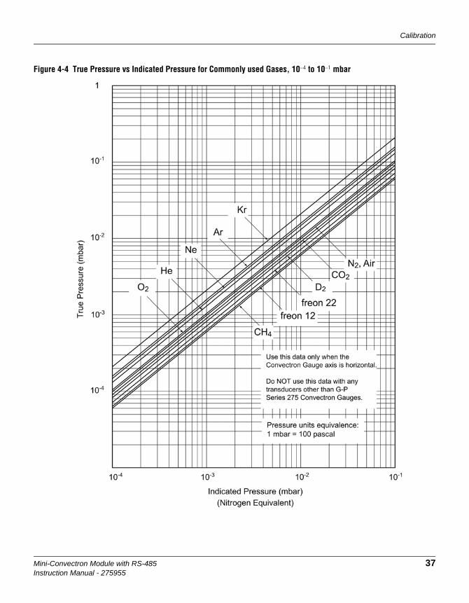
Figures 4-1 through 4-6 show the true pressure vs. indicated pressure for eleven commonly used gases. The following list will help to locate the proper graph:
A useful interpretation of these curves is, for example, that at a true pressure of 2 x 10⁻² Torr of CH4 the heat loss from the sensor is the same as at a pressure of 3 x 10⁻² Torr of N2 (see Figure 4-1). The curves at higher pressure vary widely from gas to gas because the thermal losses at higher pressures are greatly different for different gases.
The Mini-Convectron gauge tube uses convection cooling to provide resolution superior to any other thermal conductivity gauge near atmospheric pressure of N2 and air. Because convection effects are geometry dependent, the true pressure vs indicated pressure curves for the Mini-Convectron gauge tube are likely to be much different from curves for heat loss tubes made by others. Therefore, it is not safe to attempt to use calibration curves supplied by other manufacturers for their gauges with the Convectron gauge, nor is it safe to use curves for the Convectron gauge with gauges supplied by other manufacturers.
Table 4-2 Pressure vs. Indicated N2 Pressure Curve
Figure Pressure range and units Gases
Figure 4-1 10–4 to 10–1 Torr All
Figure 4-2 10–1 to 1000 Torr Ar, CO2, CH4, Freon 12, He
Figure 4-3 10–1 to 1000 Torr D2, Freon 22, Kr, Ne, O2
Figure 4-4 10–4 to 10–1 mbar All
Figure 4-5 10–1 to 1000 mbar Ar, CO2, CH4, Freon 12, He
Figure 4-6 10–1 to 1000 mbar D2, Freon 22, Kr, Ne, O2
Calibration
Mini-Convectron Module with RS-485 33Instruction Manual - 275955
If you must measure the pressure of gases other than N2 or air, use Figures 4-1 through 4-6 to determine the maximum safe indicated pressure for the other gas as explained below.
Example 1: Maximum safe indicated pressure
Assume a certain system will withstand an internal pressure of 2000 Torr or 38.7 psia. For safety, limit the maximum internal pressure to 760 Torr during backfilling. Assume you want to measure the pressure of argon. On Figure 4-2 locate 760 Torr on the left hand scale, travel to the right to the intersection with the argon (Ar) curve and then down to an indicated pressure of 24 Torr (N2 equivalent). Thus in this hypothetical situation the maximum safe indicated pressure for argon is 24 Torr.
For safety, place a warning label on the instrument which under the assumed conditions would read "DO NOT EXCEED 24 TORR FOR ARGON."
Example 2: Indicated to true pressure conversion
Assume you want to determine the true pressure of argon in a system when the Convectron is indicating 10 Torr. On Figure 4-2, read up from 10 Torr (N2 equivalent) indicated pressure to the argon curve and then horizontally to the left to a true pressure of 250 Torr. Thus 250 Torr argon pressure produces an indication of 10 Torr (N2 equivalent).
Example 3: True to indicated pressure conversion
Assume you want to set a process control setpoint at a true pressure of 20 Torr of C02. On Figure 4-2, locate 20 Torr on the true pressure scale, travel horizontally to the right to the C02 curve and then down to an indicated pressure of 6 Torr (N2 equivalent). Thus the correct process control setting for 20 Torr of C02 is 6 Torr (N2 equivalent).
Example 4: True to indicated pressure conversion
Assume you want to obtain a helium pressure of 100 Torr in the system. On Figure 4-3, locate 100 Torr on the left hand scale, travel horizontally to the right to attempt to intersect the He curve. Because the intersection is off scale it is apparent that this true pressure measurement requirement for helium exceeds the capability of the instrument.
NOTES:
For gases other than those listed, the user must provide accurate conversion data for safe operation. The Mini-Convectron gauge is not intended for use above 1000 Torr true pressure.
Ensure that the atmosphere adjustment for the Convectron gauge is set correctly. See Atmosphere Adjustment on page-31.
1 mbar = 100 pascal, so the mbar charts may be used for pascal units by multiplying the values on the axes by 100.

Chapter 4
34 Mini-Convectron Module with RS-485Instruction Manual - 275955
Figure 4-1 True Pressure vs Indicated Pressure for Commonly used Gases, 10–4 to 10–1 Torr

Calibration
Mini-Convectron Module with RS-485 35Instruction Manual - 275955
Figure 4-2 True Pressure vs Indicated Pressure for Commonly used Gases, 10–4 to 10–1 Torr

Chapter 4
36 Mini-Convectron Module with RS-485Instruction Manual - 275955
Figure 4-3 True Pressure vs Indicated Pressure for Commonly used Gases, 10–4 to 10–1 Torr
Calibration
Mini-Convectron Module with RS-485 37Instruction Manual - 275955
Figure 4-4 True Pressure vs Indicated Pressure for Commonly used Gases, 10–4 to 10–1 mbar

38 Mini-Convectron Module with RS-485Instruction Manual - 275955
Figure 4-5 True Pressure vs Indicated Pressure for Commonly used Gases, 10–1 to 1000 mbar

Calibration
Mini-Convectron Module with RS-485 39Instruction Manual - 275955
Figure 4-6 True Pressure vs Indicated Pressure for Commonly used Gases, 10–1 to 1000 mbar

Chapter 4
40 Mini-Convectron Module with RS-485Instruction Manual - 275955
Notes:

Mini-Convectron Module with RS-485 41Instruction Manual - 275955
Chapter 5 Service/Maintenance
5.1 Service Guidelines It is recommended that only qualified technical personnel attempt repairs.
If difficulties are encountered during use of your Mini-Convectron, the following list of symptoms and possible causes, along with the schematics, can prove useful in quickly getting back into operation.
If the prescribed remedies do not correct the troubles, or if additional assistance or special parts are required, contact the Technical Service Department, Granville-Phillips, 6450 Dry Creek Parkway, Longmont, Colorado, 80503. Telephone: 303-652-4400. Repairs properly made with equivalent electronic parts and rosin core solder, which do not damage other portions of the unit, do not represent a violation of the warranty.
Check Table 5-1 for the observed symptoms. This listing of symptoms and possible causes is not complete, but should be sufficient to solve most problems. All possible causes of failure should be thoroughly explored before attempting any repair.
Since the Mini-Convectron contains static-sensitive electronic parts, the following precautions must be followed when troubleshooting:
1. Use a grounded, conductive work surface.
2. Use static dissipative envelopes to store or ship printed circuit boards.
3. Do not handle the printed circuit board more than absolutely necessary, and only when wearing a ground strap.
4. Do not use an ohmmeter for troubleshooting the electronics. Rely on voltage measurements.
5. Use grounded-type soldering irons only.
5.2 Mini-Convectron Disassembly
For most troubleshooting procedures it will be required that the printed circuit board and gauge tube be removed from the enclosure. Proceed as follows to access the internal electronics and the gauge tube.
1. Disconnect the cable(s) on the side of the Mini-Convectron Module.
2. Remove the two screws on the front panel and remove the panel.
3. Slide the plastic case rearward to remove it from the gauge tube and electronics. Note that the PC Board guides are molded into the plastic case.
4. Unplug the PC board assembly from the gauge tube.
5. For assembly, reverse this procedure. Make sure the PC boards are in the slots of the plastic case.

Chapter 5
42 Mini-Convectron Module with RS-485Instruction Manual - 275955
5.3 Troubleshooting
Table 5-1 General Symptoms/Possible Causes
Symptom Possible Causes
No power indication No input power.Verify that there is +11 Vdc to +16 Vdc between pins 2 or 5 and 7 or 8 of the I/O connector. See Figure 2-4 on page 19.
Bridge output pressure reads less than .1 mTorr or greater than 1000Torr.
Gauge tube failure. Test for gauge tube failure. Measure the resistance between the following terminals with the gauge tube at atmospheric pressure and an ohmmeter which cannot apply more than 10 mA. See Mini-Convectron Disassembly on page-41for disassembly procedures.
Bridge amplifier failure. This circuitry is located on the small PC board that the gauge tube plugs into. Check for input power to this board across the two outside fingers of the small board where it is soldered into the large board. Check that the bridge output voltage between the middle finger and the bottom finger is approximately 6 Vdc with the gauge tube at atmosphere.
Readout cannot be calibrated to the specified value using TS or TZ commands
The gauge tube contaminated with material from the vacuum system. Clean the gauge tube. See Convectron Gauge Bakeout Instructions on page-44 and Cleaning a Convectron Gauge on page-44. If not effective, replace gauge tube.
• Pins 1 to 2: 18 to 23 ohms• Pins 2 to 3: 50 to 60 ohms• Pins 1 to 5: 180 to 185 ohmsIf the resistance from pins 1 to 2 reads about 800 ohms, the sensor wire in the gauge is broken. Replace the gauge tube.
Note: If the resistance values shown here are correct, but you still think the gauge is not reading correctly, the gold plating on the sensor wire may be eroded and the gauge will have to be replaced.

Service/Maintenance
Mini-Convectron Module with RS-485 43Instruction Manual - 275955
Reset the Module to Factory Defaults
Two jumpers inside the Convectron module allow the user to reset the module to the factory defaults as listed in Interface Default Settings on page-24. If the module will not respond to commands from the host, it may be necessary to reset the module to the factory default settings and the reset the desired parameters.
The jumpers are illustrated in Figure 5-1. See Mini-Convectron Disassembly on page-41 for instructions to remove the plastic case of the module to access the jumpers.
The two jumpers are labeled JP1 and JP2.
JP1 has a LO and a HI setting.
• LO causes the module address to be at the S1 position plus the SA Offset. See Set Offset Address on page-25.
• HI causes the module address to be at the S1 position plus the SA Offset plus 16.
JP2 has two settings - A "P" position and a customer programmed position.
• The "P" position causes the module to function at the factory default settings (see Interface Default Settings on page-24). When the jumper is removed from the "P" position, the module reverts to the customer programmed settings.
Readout indicating a pressure in the system is vastly different than that being observed by supporting gauges
Gas composition on system is not what the user believes it to be. This can be caused by selective gas pumping, process in use, outgassing of product, etc. Determine gas composition and calibrate accordingly.
The Convectron module will not receive commands from the host.
Communication link is not setup properly. You must assign an address to enable the module to communicates with the host. The module can be any address from 1 to 63. See Set Offset Address on page-25.The module may need to be manually reset. This is accomplished by resetting jumpers inside the module and apply power to force the communications to the factory defaults. See Figure 5-1 and Reset the Module to Factory Defaults on page-43.
Table 5-1 General Symptoms/Possible Causes
Symptom Possible Causes

Chapter 5
44 Mini-Convectron Module with RS-485Instruction Manual - 275955
Figure 5-1 Internal Jumpers
5.4 Convectron Gauge Bakeout Instructions
The Convectron gauge can be baked to 85 0C with the electronics attached, but not operational. To bake the Convectron gauge to a higher temperature, up to 150 0C, the electronics must be removed. See Mini-Convectron Disassembly on page-41for disassembly procedures.
With the electronics removed, perform the bakeout up to 150 0C. Measure the temperature at the mounting flange of the Convectron gauge.
After the system has cooled down, reassemble the electronics and connect the cable(s).
5.5 Cleaning a Convectron Gauge
Prior to cleaning, the gauge tube must be removed from the electronics as described on page 41. Cleaning solvents can damage electronic components or the enclosure.
When the small sensor wire is contaminated with oil or other films, its emissivity or its diameter may be appreciably altered and a change of calibration will result. Cleaning with trichloroethylene, perchloroethylene, toluene, or acetone is possible but it must be done very carefully to not damage the sensor.
1. Hold the gauge with the main body horizontal and the port projecting upward at a 45° angle.
2. Slowly fill the port with solvent using a standard wash bottle with the spout inserted in the port to the point where it touches the screen. Let the solvent stand in the gauge for at least ten minutes. Do not shake the
The fumes from solvents such as trichloroethylene, perchloroethylene, toluene, and acetone can be dangerous to health if inhaled. Only use these solvents in well ventilated areas exhausted to the outdoors. Acetone and toluene are highly flammable and should not be used near an open flame or energized electrical equipment.

Service/Maintenance
Mini-Convectron Module with RS-485 45Instruction Manual - 275955
gauge. Shaking the gauge with liquid inside can damage the sensor wire.
3. To drain the gauge, position it horizontally with the port facing downward.
4. Allow the gauge to dry overnight with the port vertically downward and uncapped. Before re-installing the gauge on the system, be certain no solvent odor remains.
5. If the gold plating on sensor has been attacked by a gas such as fluorine or mercury vapor, changing its emissivity and/or resistance, replace the gauge tube. Cleaning cannot solve this problem.
5.6 Returning a Mini-Convectron Module for Service
Some minor problems are readily corrected on site. If the product requires service, contact the MKS, Granville-Phillips Division Technical Support Department at 1-303-652-4400 or 1-800-776-6543 for troubleshooting help over the phone.
If the product must be returned to the factory for service, request a Return Material Authorization (RMA) from Granville-Phillips. Do not return products without first obtaining an RMA. In some cases a hazardous materials disclosure form may be required. The MKS/Granville-Phillips Customer Service Representative will advise you if the hazardous materials document is required.
When returning products to Granville-Phillips, be sure to package the products to prevent shipping damage. Shipping damage on returned products as a result of inadequate packaging is the Buyer's responsibility.For Customer Service / Technical Support:
MKS Pressure and Vacuum Measurement SolutionsMKS Instruments, Inc., Granville-Phillips® Division6450 Dry Creek ParkwayLongmont, Colorado 80503 USATel: 303-652-4400Fax: 303-652-2844Email: [email protected]
MKS Corporate HeadquartersMKS Instruments, Inc.2 Tech Drive, Suite 201Andover, MA 01810 USATel: 978-645-5500Fax: 978-557-5100Email: [email protected]

Chapter 5
46 Mini-Convectron Module with RS-485Instruction Manual - 275955
Notes:

Mini-Convectron Module with RS-485 47Instruction Manual - 275545
Index
AAddress selector 22Atmosphere adjust 31
BBaud rate 23, 28
CCalibration 31Caution statements 8Command set
RS-485 24Connector
I/O 19Power 19
Convectron GaugeInternal Volume 14Sensing Wire Filament 14
DDigital Communications 23Dimensions 18Disassembly 41
EEnvironment for installation 17Explosion / Implosion 9
FFigures
module with two relays, no display 18Frequency 29Front panel 22Fumes from solvents 9
GGrounding 17
II/O connector wiring 19Installation
environment 17grounding 17
Important Precautions 15location 17Mounting orientation 16
LLethal Voltages 11Location for installation 17
MMini-Convectron module
mounting gauges1/8 NPT mount 19compression mount/quick connect 19ConFlat flange mount 19NW16KF flange mount 19
ModulePhysical Dimensions 18Power Supply 13Temperature 13
Mounting gauges1/8 NPT mount 19compression mount/quick connect 19ConFlat flange mount 19NW16KF flange mount 19
OOffset address 25
PP > 100 mTorr indicator 22Parity 28, 29Parity settings 23Physical dimensions 18Power indicator 22Pressure
True Pressure vs. Indicated 32Pressure Measurement 13Pressure Measurement Range 13Pressure response 25
RReading and Following Instructions 8Reset 29

Index
48 Mini-Convectron Module with RS-485Instruction Manual - 275545
RS-485Command Set 24
RS-485 address switch settings 23RS-485 commands 24RS-485 wiring 20
SSafety 7
instructions 7Service Guidelines 11, 41Span 26Specifications 13
Convectron Gauge Internal Volume 14Convectron Gauge Sensing Wire 14Digital Interface 14I/O connector 13Power Supply 13Pressure Measurement 13Temperature 13
Stop bit settings 23Syntax/address overview 23System Grounding 11, 17
TTemperature
Non-operating 13Operating 13
Theory of Operation 21
VVacuum adjust 31
WWarning statements 8Wheatstone Bridge Diagram 21Wiring
I/O ConnectorSpecifications 13


Series 275
Instruction Manual
Granville-Phillips® Mini-Convectron® Module with RS-485 Interface
Instruction manual part number 275955
Revision F - November 2016
Customer Service / Technical Support:
MKS Pressure and Vacuum Measurement SolutionsMKS Instruments, Inc., Granville-Phillips® Division6450 Dry Creek ParkwayLongmont, Colorado 80503 USATel: 303-652-4400Fax: 303-652-2844Email: [email protected]
MKS Corporate HeadquartersMKS Instruments, Inc.2 Tech Drive, Suite 201Andover, MA 01810 USATel: 978-645-5500Fax: 978-557-5100Email: [email protected]