Grant Low-loss header system Installation & User ...
28
165 kW PROVISIONAL COPY 31/10/2013 Page 1 of 28 Grant Low-loss header system Installation & User Instructions 165 kW Please note these are provisional instructions if you have any queries please contact our Projects Office if you are in any doubt of the suitability of this system for your requirements. Part No. DOC.67 Rev.05 – October 2013
Transcript of Grant Low-loss header system Installation & User ...

165 kW PROVISIONAL COPY
31/10/2013 Page 1 of 28
Grant Low-loss header system Installation & User Instructions 165 kW
Please note these are provisional instructions if you have any queries please contact our Projects Office if you are in any doubt of the suitability of this system for your requirements. Part No. DOC.67 Rev.05 – October 2013

165 kW PROVISIONAL COPY
31/10/2013 Page 2 of 28
Sec Sub sec Contents Page 1 Introduction 3 2 Technical Specification 165kW 4 2.1 Basic dimensions 165kW switcher and header 4 2.2 Kit contents 165kW header system 5 – 6 2.3 Technical data switcher and header 165kW 7 2.4 Technical data constant temperature zone pump kits 8 2.5 Technical data variable temperature zone pump kits 8 2.6 Technical data zone pump kit performance graphs 9 2.7 Technical data high efficiency pumps overview 10 – 11 2.8 Technical data electrical connection 11 – 12 2.9 Technical data pump head electronic control 13 – 14
3 Description of header system operation 165kW 15 3.1 Description and operation 165kW 15 – 16
4 Three way mixing valve (variable temperature) 17 4.1 Description of operation three way mixing valve 17 4.2 Fitting the 3 port mixing valve non – return valve 17 4.3 Fitting the 3 port valve motor 18 – 20
5 General system information 165kW 21 5.1 Multiple appliances 21 5.2 Open vented system connection 22 5.3 Feed and expansion pipe sizing 22 5.4 Sealed systems 23 5.5 Sealed system connection 23 5.6 Safety device 24 5.7 Pipe sizing 24
6 Commissioning 25 6.1 General 25 6.2 Filling and flushing the system 25 6.3 Fault finding 25 - 26
7 Servicing 27 7.1 Servicing 27
8 Guarantee 28 8.1 The Grant Header System Guarantee 28

165 kW PROVISIONAL COPY
31/10/2013 Page 3 of 28
1. Introduction These Installation instructions should be read carefully before installing the Grant Low – loss header system and must be used in conjunction with the Installation & User instructions supplied with the boiler. We recommend before installing the Grant Low – loss header system you attend a Grant Systems Control Installer training course. The Grant Low – loss header system is a cost effective way of installing multiple heat sources and feeding more than one heating zone which have different temperature requirements. It is designed specifically for use with the Grant heat producing appliances such as our Oil, Spira wood pellet and Air source heat pumps, and should not be used for any other application. Grant Engineering UK Ltd shall not be liable for any injury or damage arising from the incorrect use of this system. For correct usage, refer to these Installation and User instructions. Installation of the Grant Low – loss header system, must be installed by a competent person in accordance with all current legislation, codes of practice and local by-laws relating to the installation of heating systems and appliances. The electrical installation must comply with the requirements of the Electricity at Work Regulations 1989 and BS7671:2008 - IEE Wiring Regulations 17th Edition (including all amendments). All installations of Grant Vortex Oil and Spira wood pellet boilers must comply with the relevant Building Regulations.

165 kW PROVISIONAL COPY
31/10/2013 Page 4 of 28
2. Technical Specification – 165kW 2.1 Basic dimensions – 165 kW switcher and header Figure 2.1 165kW switcher and header details Item description Letter Dimension
mm Overall length of header – 2 zone pumps A 555 Overall length of header – 3 zone pumps A 805 Overall length of header – 4 zone pumps A 1055 Overall length of header – 5 zone pumps A 1305 Overall length of header – 6 zone pumps A 1555 1¼" male thread for open vent connection or safety device B 1¼" BSP ½" female socket for flow sensor pocket C ½" BSP ½" female socket for drain D ½" BSP Fixing centre for wall brackets – 2 & 3 zone pumps E 375 Fixing centre for wall brackets – 4 & 5 zone pumps E 625 Fixing centre for wall brackets – 6 zone pumps E 875 N.B. All dimensions are nominal please check against actual headers before proceeding with installation.
Table 2.1 165kW switcher and header dimensions

165 kW PROVISIONAL COPY
31/10/2013 Page 5 of 28
2. Technical Specification 2.2 Kit Contents – 165 kW header system The Grant Low – loss header system 165 kW containing the following:
• 1 x Hydraulic switcher • 1 x Distribution header • 1 x 2" Connection kit (including 3 - 2" unions) for the above • 1 x Set of wall fixings • The required number of System Zone pump kits as required, 7 or 8 M head • 1¼" Isolation valves to connect Distribution header to Zone pump kit. • Installation & User Instructions
Note. All electrical cable and pipe work required to connect the Grant header system to the appliances and heating circuits to be supplied by installer.
Draw No
Part description Further information Grant Part number
20 2" Vertical Hydraulic Switcher – 165 kW Note: 165 kW @ 20º∆t GHS80/570
20B Header bracket set wrap over 160mm GHS/WF160
20C Header wall fixing set 160mm Only 1 set per Header Required
GHS/WFHV160
21 2" Connection Kit Only 1 per header GHS076929
22 1¼" F & R Distributor GHS80/1252
23 1¼" F & R Distributor GHS80/1253
24 1¼" F & R Distributor GHS80/1254
25 1¼" F & R Distributor GHS80/1255
26 1¼" F & R Distributor
2 – 6 is the number of pump units (circuits) per installation as required by the installer (see drawings)
GHS80/1256
28 1¼" Isolation Valves 2 valves per pump station GHS/55AMMS
29 Safety set up to 200kW Note: 3 Bar PRV GHS/SG200
35 32mm Constant temperature 7M pump station GHS/CT05
36 32mm Constant temperature 8M pump station
Constant temp, variable speed for Heating & Hot Water Primary circuits GHS/CT06
37 32mm Variable temperature 7M pump station GHS/VT07
38 32mm Variable temperature 8M pump station
For Heating circuits only. With mixing valve used with GEO 360 W/comp GHS/VT08
Table 2.1 kit contents 165kW itemised parts list

165 kW PROVISIONAL COPY
31/10/2013 Page 6 of 28
2. Technical Specification 2.2 Kit Contents – 165 kW Header – continued
Figure 2.2 A typical header system showing the itemised parts

165 kW PROVISIONAL COPY
31/10/2013 Page 7 of 28
2. Technical Specification 2.3 Technical Data – switcher and header165kW 165 kW Hydraulic switcher Max 6 Bar Hydraulic switcher – max flow rate Up to 7m³/h, @ 20° Δ t Hydraulic switcher – dimensions (including insulation) 152 x 152 x 770mm (high)
Hydraulic switcher connection – appliances (Boilers etc) 2 x 2" Male iron
Hydraulic switcher connection – to insulated distributor 2 x 2" Male iron
Hydraulic switcher connection – flow sensor pocket ½" Female iron
Hydraulic switcher top connection – vent/PRV 1¼" Male iron thread for security unit
SG 200 Hydraulic switcher bottom connection - drain ½" Female iron Hydraulic switcher – Wall fixing 152 x 152 – 160mm wall - centre 165 kW Distributor Distributor max flow rate – distributor per 1¼" Zone pump connection Up to 3m³/h, @ 20° Δ t
Distributor insulated – dimensions (inc threads) 150 x 150 x 625 – 1625mm max (length)
Distributor – zone pump connections 2 – 6 x 1¼" connections for
Zone pump kits Distributor – side connections (for left or right hand connection of the hydraulic switcher) 2" Male iron
Distributor – bottom connections (for left or right hand connection of the hydraulic switcher) including 2 x 2" Cap ends to blank unused connections
2" Male iron
Distributor – Wall fixings 150 x 150 x 100 or 150mm wall – centre Table 2.3.1 Header and switcher information 165 kW Hydraulic switcher Length mm Inc 2" threads
Cross section mm Litres Approximate total header and switcher volume in Litres
750 150 x 150 (less insulation) 7.50 165 kW Distributors 625 150 x 150 (less insulation) 5.75 13.25 875 8.25 15.75 1125 10.75 18.25 1375 13.25 20.75 1625 15.75 23.25 Table 2.3.2 Header and switcher fluid volumes

165 kW PROVISIONAL COPY
31/10/2013 Page 8 of 28
2. Technical Specification 2.4 Technical Data – Constant temperature zone pump kit Zone pump kits for the 165 kW header Figure 2.4.1 Comprises – pump, isolation ball valves, temperature gauges inc non return valve Constant temperature variable speed
Connection sizes 1¼" Female iron top connection 1¼" Female iron bottom connections via
1¼" x 2" unions supplied not shown Dimensions W X H X D 250 x 380 x 190mm Maximum temperature 110° C Non return valve – operate at 20mb Built in to return valve Application – 7 & 8m head Hot water and heating circuits’ Flow rate – 7 & 8m head 70kW 3m³/h, @ 20° Δ t Table 2.4.1 Constant temperature zone pump details
Figure 2.5.1 Variable temperature Figure 2.4.1 Constant temperature 2.5 Technical Data – Variable temperature zone pump kit Zone pump kits for the 165 kW header Figure 2.5.1 Comprises – pump, isolation ball valves, temperature gauges inc non return valve
Variable temperature & variable speed
Connection sizes 1¼" Female iron top connection 1¼" Female iron bottom connections via
1¼" x 2" unions supplied not shown Dimensions W X H X D 250 x 380 x 190mm Maximum temperature 110° C Non return valve – operate at 20mb Built into return valve + mixer Application – 7 & 8m head Weather compensated heating circuits Flow rate – 7 & 8m head 70kW 3m³/h, @ 20° Δ t
Additional controls Built in mixing valve and servomotor for
use with Grant GEO 360 weather compensated heating circuits
Table 2.5.1 Variable temperature zone pump details

165 kW PROVISIONAL COPY
31/10/2013 Page 9 of 28
2. Technical Specification 2.6 Technical Data – zone pump kit performance graphs
Zone pump kit 165 kW
Size Type 6m 7m 8m Constant
temperature N/A STRATOS PARA – 30/1-7 STRATOS PARA – 30/1-8 1¼"
Variable temperature N/A STRATOS PARA – 30/1-7 STRATOS PARA – 30/1-8
Table 2.6.1 Constant/variable temperature zone pump details Figure 2.6.1 Constant/variable temperature STRATOS PARA 30/1 – 7 pump graphs
Figure 2.6.2 Constant/variable temperature STRATOS PARA 30/1 – 8 pump graphs

165 kW PROVISIONAL COPY
31/10/2013 Page 10 of 28
2. Technical Specification 2.7 Technical Data – high efficiency pumps overview Constant/variable temperature STRATOS PARA RS 30/1 – 7/8 High – efficiency pumps Overview ERP – Energy related products. Following Kyoto Protocol from December 1997 , the EU has set up measures to achieve a 20% reduction on both energy consumption and CO2 – emissions until 2020, based on the data from 1990. One of these measures is the ErP Directive. Conformity with the derived EU regulations will be governed through mandatory CE Marking The latest ErP (Energy related Products) directive is ErP 2009/125/EC which also covers products such as windows as well as pumps etc. Since 1st January 2013, glandless stand alone circulators, with the exception of those specifically designed for primary circuits of thermal solar hot water and of heat pumps, shall have an energy efficiency index (EEI) of not more than 0.27. From 1st August 2015 stand alone circulators and circulators integrated into products shall have an energy efficiency index (EEI) of not more than0.23. A product is an appliance that generates heat, boilers, heat pumps, solar hot water, district heating and DHW boiler. Electronic performance control Heating pumps due to their high annual operating hours are among the largest power consuming appliances in buildings. Automatic pump performance control will help drastically reduce power consumption. A further significant effect connected with the prevention of a rise in pump pressure is the avoidance of flow noise in systems. EC motor EC stands for electronically controlled motor, a synchronous motor with permanent magnate rotor. The rotating stators magnetic field is generated by electronic communication, meaning that the stator windings are activated specifically for the interaction of the electrical and magnetic poles. The benefits The magnetic field required in the rotor does not need to be generated with any losses. Especially in part load range (up to 98% of the operating time) the difference in efficiency is even greater than it is already in the full load range compared to an asynchronous motor. High speeds are possible, this results in the reduction in size and weight of the unit compared with a traditional circulating pump.

165 kW PROVISIONAL COPY
31/10/2013 Page 11 of 28
2. Technical Specification 2.7 Technical Data – high efficiency pumps overview Constant/variable temperature STRATOS PARA RS 30/1 – 7/8 Permissible temperature range The Wilo – Yonos Para range is equipped with a self protecting mode. In the event of too high a temperature, outside the permissible temperature range, the electronics will automatically reduce the power consumption until normal operating conditions return.
Example: at a fluid temperature of 90 C and at an ambient temperature of 59 C, the delivery head can decrease by 0.5m depending on the pressure losses of the system 2.8 Technical Data – electrical connection Electrical connection To ensure a safe and easy electrical connection, the Wilo – Para pumps are equipped with a mains 3 core cable with brass end splices. Optional Wilo connector No tools are required to connect the mains cable to the Wilo connector. Strip the heat resisting cable conductor insulation by 7mm and strip the outer cable insulation by 32mm. See the following illustrations:

165 kW PROVISIONAL COPY
31/10/2013 Page 12 of 28
2. Technical Specification 2.8 Technical Data – electrical connection Electrical connection
1 2 3
4 5

165 kW PROVISIONAL COPY
31/10/2013 Page 13 of 28
2. Technical Specification 2.9 Technical Data – pump head electronic control Constant/variable temperature STRATOS PARA RS 30/1 – 7/8 Electronic performance control The three modes of operation Control mode Up-c: Constant differential pressure In this setting the pump will operate up to the HS (head setting)
Pump control symbol Pump graph Control mode Up-v: Variable differential pressure In this setting the pump will change the differential set point to be maintained by the pump in a linear fashion between Hs and ½ Hs. The differential pressure set point value H varies with the volume flow Q
Pump control symbol Pump graph Venting routine
Pump control symbol The integrated venting routine supports a bleeding of the overall heating system. After a manual setting, the routine runs for 10 minutes alternating at low and high speed of the pump every 15 seconds. At the end of the process, the pump will switch automatically to a preset speed. After that, the desired control mode can be set on the red button.

165 kW PROVISIONAL COPY
31/10/2013 Page 14 of 28
2. Technical Specification 2.9 Technical Data – pump head electronic control Constant/variable temperature STRATOS PARA RS 30/1 – 7/8 Control selector with Red LED Constant Δp and variable Δp working mode and air vent program can be selected by means of the RED knob. The LED indicator, shown here in GREEN, (placed around the selector knob), indicates the working state of the circulator or the presence of any problems. 1 Constant Δp 1 2 Air vent mode 2 3 Variable Δp 3 4 Green LED 4
Figure 2.9.1 Control selector with red LED Continuous green LED Regular working or air vent program ended Intermittent green LED Air vent program in progress Intermittent green and red LED Irregular working, the circulator will start again as
soon as the anomaly is worked out i.e. excessive temperature.
Intermittent red LED Stopping problem, circulator stopped. Switched off LED No power supply or electrical failure. Figure 2.9.2 Control LED colours

165 kW PROVISIONAL COPY
31/10/2013 Page 15 of 28
3. Description of header system operation – 165kW 3.1 Description and operation – 165kW Figure 3.1 Header flow path The 165kW Grant header system has two major components the ‘Vertical Hydraulic switcher’ for connecting the heat source, (appliances, boilers air source heat pumps etc) and the ‘Distribution header’ this is connected to the switcher by two 2" unions and a 2" pipe bend (pre – insulated). The distribution header supports the ‘Zone pump kits’ which distribute the heat to the system. Why is it called a ‘Low loss header? If we take the supply pipework from the appliances which for a 165kW input @ 20° Δ t flow and return differential would be say 54 mm diameter pipe. The resistance reading from a pipe chart for 1.9643 kgs/sec (165kW @ 20° Δ t) would be 0.016 m/m, when the water enters the ‘Switcher – low loss header) this is 100mm square. If we take a reading for a 100mm copper pipe we would find that the loss of head per metre run for 1.9643kgs/sec would only be 0.0018 m/m. As can be seen there is 10 times less head loss per metre in our low loss header, hence the expression ‘low loss’ header. The zone pump kits then draw their system water off the distribution header to the appropriate circuits. At the same time cooler return water is returned to the ‘Hydraulic switcher’ and mixed back into the return for the appliances or re – used back into the system flow. It is important that every circuit is correctly balanced to make sure that the system water temperature differentials are set. For suggested flow rates and differentials see the table below.
Distribution header capacity – 165kW Δ t kgs/s* l/h m³/h
Maximum input from heat sources 1650,000 watts @ 20 1.9643 7,000 7.0
82,500 watts @ 10 1.9643 3,000 7.0 41,250 watts @ 5 1.9643 3,000 7.0
1¼" Zone pump kits 70,000 watts @ 20 0.833 3,000 3.0 35,000 watts @ 10 0.833 3,000 3.0 17,500 watts @ 5 0.833 3,000 3.0
* Based on the formula watts divided by temp differential multiplied by specific heat of water. Table 3.1 165kW output values As can be seen in the above table it is important to obtain the correct flow rate and temperature differential in order to carry the amount of energy required for the system. As an example, if we used four 36kW Grant Spira wood pellet boilers, with a flow and return temperature differential of 20°K this will produce the rated output of 36 x 4 = 144kW. This would be suitable on this 165kW system, whereas if we used 3 Air source heat pumps, say rated at 14.8 kW at -3°C set up with a Δt of 5°K we would be just over the maximum at 44.4 kW. All pipework sizing calculations must be sized by the installer/heating engineer before proceeding with the installation.

165 kW PROVISIONAL COPY
31/10/2013 Page 16 of 28
3. Description of header system operation – 165kW 3.1 Description and operation – 165kW (continued)
Figure 3.2 Flow and return connections NB: The flow connection is always on the TOP with the flow sensor POCKET above the flow connection as shown. It is always preferable to have the header system above the top connection of the appliance to prevent pipe dips and air entrapment, but this is not essential as systems have been installed where the appliance top tapping is higher than the ‘Header switcher’, but auto air vents (use the safety unit as shown which includes an Automatic air vent 3 Bar pressure relief valve and Pressure gauge) may be required, please follow the appliance manufactures installation instructions. A suitable solid wall is preferable to minimise the transmission of any vibration or mechanical noise transmitted by the Zone pump units and to be able to carry the weight of the installation, some metal frame plasterboard partitions may not be suitable. The header system is attached to the wall using wall fixing brackets for dimensions see the dimensions page 4 for more detail. The ‘Header switcher’ is connected to the ‘Distribution header’ using 2" Galvanized pipe and unions; threaded joints may be made water tight with a suitable compound or PTFE tape. If a paste is to be used on the union faces this should be used sparingly so as to prevent ingress by the paste into the system. The pump flanges have a rubber washer these should be installed without any paste ‘dry’ to prevent spreading of the gasket. The Grant header system may be used with either a vented or sealed heating layout; all installations must comply with relevant standards and Building Regulations as appropriate. The Grant header system will not require a by pass valve between the appliances and the switcher header as the switcher is an open pipe allowing the water to circulate through the appliances without hindrance. Back end protection would not normally be required if the boilers are commissioned and the flow rates set up for the correct operation of the appliances, under normal working conditions the return would not be expected to rise above 57° C.

165 kW PROVISIONAL COPY
31/10/2013 Page 17 of 28
4. Three way mixing valve (variable temperature) 4.1 Description of operation three way mixing valve
Figure 4.1
Flow Return Flow
3 Port operation with a 90° movement of the valve shoe from open to closed. Open – no mix from the return, motor valve scale at ‘10’ heating flow and return operate without compensation.
50% mix 100% mix F & R F & R Return Flow
Fully closed – the return water is re - circulated back into the system, motor scale at ‘0’, the valve shoe is across the flow from the heat source. Weather compensation will be a position between fully open and fully closed. 4.2 Three way mixing non – return valve When a variable temperature DN35 zone pump with 3 port mixing valve is used it is important that an additional NRV is fitted in the return connection as shown in Figure 4.2 This will prevent the possible recirculation of the return into the 3 way mixing valve as shown. Please Note: The check valve is held in place by the union as shown. Figure 4.2

165 kW PROVISIONAL COPY
31/10/2013 Page 18 of 28
4. Three way mixing valve (variable temperature) 4.3 Fitting of 3-port valve motor Unscrew retaining screw and remove black knob from valve shaft Fit anti-rotation stud (supplied with motor) into threaded hole in valve body and tighten Fit grey adaptor (supplied with motor) onto valve shaft Rotate shaft to align pointer on grey adaptor with closed position on valve scale (at ‘9 – o’clock ’ position)

165 kW PROVISIONAL COPY
31/10/2013 Page 19 of 28
4. Three way mixing valve (variable temperature) 4.3 Fitting of 3-port valve motor (continued) Fit the valve scale (supplied with the motor) over the splined shaft end IMPORTANT: ensure ‘0’ is to the left Using a flat bladed screwdriver push in and rotate the motor release to switch from ‘auto’ to ‘manual’ operation of the motor/valve Fit the valve lever (supplied with the motor) onto the splined shaft end Rotate lever anticlockwise to point to ‘0’ position on scale

165 kW PROVISIONAL COPY
31/10/2013 Page 20 of 28
4. Three way mixing valve (variable temperature) 4.3 Fitting of 3-port valve motor (continued) Fit the motor onto valve shaft/adaptor with the scale at the left hand end Locate anti-rotation stud into groove in the underside of the motor housing Fit the long fixing screw (supplied with the motor) and tighten to secure motor/lever to valve shaft Manually operate valve - move lever anticlockwise to closed ‘10’ position to check operation then reset to ‘0’ Using screwdriver - re-set motor release to ‘auto’ (A) position
165 kW PROVISIONAL COPY
31/10/2013 Page 21 of 28
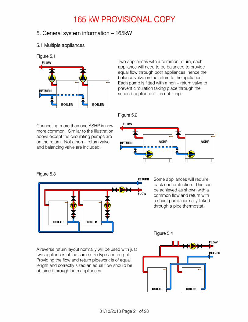
5. General system information – 165kW 5.1 Multiple appliances Figure 5.1
Two appliances with a common return, each appliance will need to be balanced to provide equal flow through both appliances, hence the balance valve on the return to the appliance. Each pump is fitted with a non – return valve to prevent circulation taking place through the second appliance if it is not firing. Figure 5.2
Connecting more than one ASHP is now more common. Similar to the illustration above except the circulating pumps are on the return. Not a non – return valve and balancing valve are included. Figure 5.3
Some appliances will require back end protection. This can be achieved as shown with a common flow and return with a shunt pump normally linked through a pipe thermostat. Figure 5.4
A reverse return layout normally will be used with just two appliances of the same size type and output. Providing the flow and return pipework is of equal length and correctly sized an equal flow should be obtained through both appliances.

165 kW PROVISIONAL COPY
31/10/2013 Page 22 of 28
5. General system information – 165kW 5.2 Open vented systems
Figure 5.2.1 Multiple appliance Figure 5.2.2 Multiple appliance installation open vent off hydraulic switcher installation open vent off flow to
hydraulic switcher. 5.3 Feed and expansion pipe sizing According to the Water supply (Water fittings)regulations 1999 and the Scottish water byelaws 2004, and BS EN 12828 the minimum size for the expansion pipe on a heating system should be no less than 19mm internal diameter. The Domestic heating design guide gives recommended sizes for boilers up to 25kW output 22mm OD and 25 – 60 kW output 28mm OD diameter vent pipe, these are guide lines. BS EN gives a formula which the following table is based. Safety pipe:
ds = 15 + 1.4 √Ф Feed and expansion
dfe = 15 + 1.0 √Ф Ф is the nominal output of the heat generator in kilo Watts (kW) Figure 7 – 2 – 4 Suggested open vent and cold feed pipes in copper tube
165kW
id OD
Vent 39 42
Cold feed 28 35 Note: The low loss header is the neutral point of the system therefore the circulating pumps must always pump away from the vertical header, this will maintain a positive pressure within the appliance and the system. See Domestic Heating Design Guide 2013 page 85.

165 kW PROVISIONAL COPY
31/10/2013 Page 23 of 28
5. General system information – 165kW 5.4 Sealed systems Sealed systems expansion vessels and pressure relief valves BS EN 12828 Annex D (informative) and the Water supply (Water fittings)regulations 1999 and the Scottish water byelaws 2004, also cover the installation of sealed heating systems, guidance can be found in the Domestic heating design guide. The diagrams on the following pages demonstrate basic guidance for the installation of the sealed system and its components; it is the responsibility of the installer to check with the appliance manufactures and current legal requirements when installing such systems.
1. Calculate the total volume of the system to enable the correct size of expansion vessel required.
2. The initial vessel pressure should be at least that of the static pressure, nominally 1 bar, this would represent an approximate static head of 10 metres. The final system pressure should be 0.2 – 0.3 bar greater than the expansion vessel pressure.
3. The position of the expansion vessel in the system determines the neutral point in the system; this is where the system pressure is always constant. The expansion vessel should be connected to the suction side of the circulating pump to ensure a positive pressure in all parts of the system.
4. The fill position should be between the connection point of the expansion vessel and the inlet of the circulating pump.
5. For vessel sizing refer to the Heating Design guide or Table D.1 in BS EN 12828:2003
6. Sealed systems should be fitted with a non – adjustable safety valve set to lift at a gauge pressure not exceeding 3 bar (300 kPa), fitted close to the appliance with a discharge to a tundish with a suitable metal discharge pipe in accordance with the appliance manufactures and current regulations and standards.
5.5 Sealed system connection 5.5.1 Sealed system up to 165kW
Figure 5.5.1 Shows a single appliance connected to a sealed system with removable filling loop, an expansion vessel pressure relief valve and pressure gauge. Consideration should be given to the correct sizing of the expansion vessel which should comply with BS 4814 Automatic and manual air vents should be fitted at high points in the system to completely remove all air when commissioning the system
Figure 5.5.1 Single appliance installation
165 kW PROVISIONAL COPY
31/10/2013 Page 24 of 28
5. General system information – 165kW 5.6 Safety device
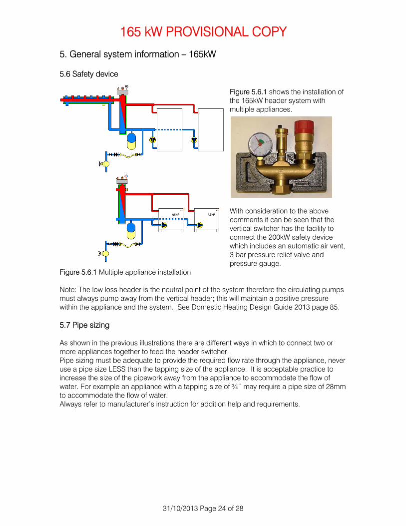
Figure 5.6.1 shows the installation of the 165kW header system with multiple appliances.
With consideration to the above comments it can be seen that the vertical switcher has the facility to connect the 200kW safety device which includes an automatic air vent, 3 bar pressure relief valve and pressure gauge.
Figure 5.6.1 Multiple appliance installation Note: The low loss header is the neutral point of the system therefore the circulating pumps must always pump away from the vertical header; this will maintain a positive pressure within the appliance and the system. See Domestic Heating Design Guide 2013 page 85. 5.7 Pipe sizing As shown in the previous illustrations there are different ways in which to connect two or more appliances together to feed the header switcher. Pipe sizing must be adequate to provide the required flow rate through the appliance, never use a pipe size LESS than the tapping size of the appliance. It is acceptable practice to increase the size of the pipework away from the appliance to accommodate the flow of water. For example an appliance with a tapping size of ¾¨ may require a pipe size of 28mm to accommodate the flow of water. Always refer to manufacturer’s instruction for addition help and requirements.

165 kW PROVISIONAL COPY
31/10/2013 Page 25 of 28
6. Commissioning the system for 165kW headers 6.1 General The commissioning of a heating system in the words of the CIBSE Guide B states “Commissioning means the advancement of these systems from the state of static completion to working order to the specified requirements of the approved design” In regard to our header system this will mean that after we have filled and flushed our system and removed all unwanted air. We may put the system into operation with due regard to electrical requirements including the correct earthing arrangements for the system all in accordance with the current regulations and BS7671. Water flow rate, it is advisable that wherever possible valves should be fitted to all equipment to enable the correct flow rate to be achieved through the equipment. The correct flow and return temperatures also need to be checked to ensure the correct amount of energy is being carried through the system as described in Section 3 page 15 6.2 Filling and flushing the system Reference should be made to the appropriate standards in regard to filling and flushing of the heating system and circuits. In domestic properties BS 7593:1992 advises the use of a full bore drain valve at the lowest point of the system and also a full bore drain point at the boiler. This is to facilitate the complete draining and flushing of the system. Some chemical manufactures have produced a high powered flushing pump system for this purpose. It is the responsibility of the installer/commissioning engineer to make sure the system has had all foreign matter removed and to ensure it is free of flux residues, metal swarf, solder pieces and if an existing system magnetite deposits removed. The use of propriety chemical cleaners and agents will help in this process providing the manufacturers instructions are adhered to. Upon the completed filling and flushing of the system procedure it is also the responsibility of the installer/commissioning engineer to ensure that all the air has been removed from the system and heat emitters and pumps. 6.3 Fault finding If the correct procedure for the filling and venting of the system is carried out there should be no need for fault finding, but in the event that a system is not functioning as it should then the following method of fault detection may be used. Always remember the basic method when fault finding, is there power, or fuel and in the case of the header system is there system fluid.

165 kW PROVISIONAL COPY
31/10/2013 Page 26 of 28
6. Commissioning the system for 165kW headers 6.3 Fault finding Mechanical Solution Electrical Solution No circulation Check for water in the
system N/A Fill system
System not heating up (Luke warm) radiators not heating up
Check flow and return connections into switcher (Flow should be on the right with sensor pocket alongside)
No circulation through zone pumps
Check valves are fully open, above and below pumps
Pumps noisy Check for air in pump, release central bleed screw on pump, also check for pump rotation
Ditto Carry out electrical safety checks. Check for power from fused spur. Check for heating/hot water demand from controls. Check for power to pumps at the pump terminals Check for continuity
Reverse circulation through pumps
Check non – return valves are fitted into Zone pump kit as per installation instructions
N/A
Insufficient heat from appliances
Check appliance pumps (see above) Check valves are fully open (see above) Check appliances are of sufficient output for the heat load of the installation
Ditto See above
Individual circuit not working correctly
Check pump, valves, non return valves and any system valves are open (see above)
Ditto See above
Table 6.1 Fault finding the header installation

165 kW PROVISIONAL COPY
31/10/2013 Page 27 of 28
Servicing 7 Header systems 165kW 7.1 Servicing. Service requirements for the Grant Header systems are minimal but checks must be carried out as part of the appliance annual service. The basic checks should include;
1. Isolate the power supply and remove insulation to the Zone pumps, check for mechanical damage to the covers, if required contact Grant Engineering UK Ltd for replacement insulating covers.
2. With the zone pumps exposed check all connections for water tightness and make good any leaks from joints. If required replace gaskets and jointing to threads, refit and test. Check pump for air via the large screw on the front of the pump, do this without the pump being energised.
3. Visually check the condition of any electrical flex/wiring to the zone pumps, if there is any sign of deterioration of the insulation, replace the flex with a suitable new flex/wiring to the correct specification for the zone pump.
4. If there is a weather compensator mixing valve fitted to the heating zone pump remove the actuating motor and check the drive shaft for leaks. Check the condition of the actuating motor if damaged replace. Refit actuating motor and before recommissioning the system carry out a ‘Test’ using the ‘Test’ button on the GEO360 control.
5. Testing the control, see GEO360 control and press the ‘Test’ button, this will carry out a built in test routine which will test the main control functions and continually monitor the fitted sensors and relays, if there is a problem an error message will be displayed on the control screen. (see GEO360 instructions for a list of error codes) During the test the valve will rotate. This will take approximately 130 seconds, (see adjust menu).
6. Check pump and system operation when recommissioning. Check flow and return differentials to maintain system maximum efficiency.
7. Hand over to customer and explain the operation of the system and the benefits of having regular annual servicing to keep the system operating at its maximum efficiency.

165 kW PROVISIONAL COPY
31/10/2013 Page 28 of 28
8. Guarantee 8.1 The Grant Header System Guarantee Dear Customer You are now the proud owner of a Grant Header System from Grant Engineering (UK) Ltd, which has been designed to give years of reliable, trouble free operation. Grant Engineering (UK) Ltd. guarantees the manufacture of the Grant Header System for a period of Five years from the date of installation, unless the installation was more than six months from the date of purchase, in which case the Guarantee period will commence six months from the date of purchase, provided the Grant Header System is installed in full accordance with the installation instructions provided. If a replacement Grant Header System is supplied under the Guarantee (due to a manufacturing fault) the product Guarantee continues from the installation date of the original Grant Header System, and not from the installation date of the replacement. GEO360 and GES264 controls supplied with the header system are guaranteed for a period of Three years from the date of installation. Circulating pumps supplied with the Grant header system are guaranteed for a period of Two years from the date of installation. Contact details are Grant Engineering Hopton House Hopton Industrial Estate Devizes Wiltshire SN10 2EU TEL: 01380 736985 FAX: 01380 736991 EMAIL: [email protected] WEB SITE: www.grantuk.com