GRANT AGREEMENT NUMBER: 323378 PROPOSAL ACRONYM: GOTA … · The GOTA project has completed its...
63
GRANT AGREEMENT NUMBER: 323378 PROPOSAL ACRONYM: GOTA PROJECT FULL TITLE: GREATER OPERATING TEMPERATURE ALLOY FUNDING SCHEME: FP7-JTI-CS DATE OF LATEST VERSION OF ANNEX I: 05/02/2013 PERIOD NUMBER: 3 (START DATE: 1/3/15 END DATE: 30/4/2016) PROJECT COORDINATOR: ROGER THOMAS, TIMET UK LTD (email: [email protected]) MILESTONE 7: RESULTS OF TESTING AND CHARACTERISATION LIST OF PARTICIPANTS: PARTICIPANT NO. PARTICIPANT ORGANISATION NAME COUNTRY 1 (COORDINATOR) TIMET UK LTD. UNITED KINGDOM 2 FORGITAL ITALY S.P.A. ITALY 3 DERITEND INTERNATIONAL LTD. UNITED KINGDOM 4 SWANSEA UNIVERSITY UNITED KINGDOM RESTRICTIONS This periodic report may contain information that is company confidential. The information contained in this document is provided to the European Union for the express purpose of evaluating the project work against the requirements of the Clean Skies JTI and may be distributed to appropriate support contractors and non-Government consultants as required to complete the technical and administrative review. Any other use of non-public information contained herein is prohibited without TIMET’s express written consent.
Transcript of GRANT AGREEMENT NUMBER: 323378 PROPOSAL ACRONYM: GOTA … · The GOTA project has completed its...

GRANT AGREEMENT NUMBER: 323378 PROPOSAL ACRONYM: GOTA PROJECT FULL TITLE: GREATER OPERATING TEMPERATURE ALLOY FUNDING SCHEME: FP7-JTI-CS DATE OF LATEST VERSION OF ANNEX I: 05/02/2013 PERIOD NUMBER: 3 (START DATE: 1/3/15 END DATE: 30/4/2016) PROJECT COORDINATOR: ROGER THOMAS, TIMET UK LTD (email: [email protected])
MILESTONE 7: RESULTS OF TESTING AND CHARACTERISATION
LIST OF PARTICIPANTS:
PARTICIPANT NO. PARTICIPANT ORGANISATION NAME COUNTRY
1 (COORDINATOR) TIMET UK LTD. UNITED KINGDOM
2 FORGITAL ITALY S.P.A. ITALY
3 DERITEND INTERNATIONAL LTD. UNITED KINGDOM
4 SWANSEA UNIVERSITY UNITED KINGDOM
RESTRICTIONS This periodic report may contain information that is company confidential. The information contained in this document is provided to the European Union for the express purpose of evaluating the project work against the requirements of the Clean Skies JTI and may be distributed to appropriate support contractors and non-Government consultants as required to complete the technical and administrative review. Any other use of non-public information contained herein is prohibited without TIMET’s express written consent.
1. Introduction:
1 (a) Milestone 7.
The GOTA project has completed its third period of performance with the testing of sample
materials manufactured to represent cast, forged and welded components. Milestone 7 is a report
summarizing all the testing and characterization performed in the project.
1 (b) Project Context and Objectives. The GOTA project selected Timetal 834 (Ti-834) as the candidate titanium alloy for long term service use in aero engine intermediate compressor casing (ICCs) at temperatures 50°C higher than those currently applied to alloy Ti-6242S, and then manufacture and test the Ti+ alloy. The partners have demonstrated the industrial scale manufacture of this titanium alloy as castings and as rolled rings; sheet and weld wire, and demonstrated the fabrication by laser welding of the alloy, Swansea University has undertaken a programme of testing and characterization of these materials, both characterizing the materials as manufactured, and evaluating the durability of the materials after exposure to the proposed operating temperature for extended periods. 1 c) Metallurgical Background
In ICC applications Ti-834 alloy would be required to operate at temperatures approaching 500°C,
which is approximately 50°C higher than is currently possible using the Ti-6242S alloy. The
replacement alloy will also need to demonstrate suitable mechanical properties after prolonged
exposure at operating temperatures.
Near alpha (α) titanium alloys such as Ti-6242S are used extensively for intermediate temperature
applications such as gas turbine ICCs. These types of high temperature alloys are selected due to
their balance of strength, fatigue and creep properties. However after prolonged exposure to high
temperatures these titanium alloys are known to experience a reduction in mechanical properties
[1], [2],[3], [4],[5]. The reduction in fatigue and creep performance is essentially attributed to the
formation of α case at the surface of the alloy. Reductions in ductility are not so well understood
and cannot solely be correlated with the formation of α-case. Previous studies [1],[6] have
attributed the loss in ductility to the precipitation of coherent Ti3Al or α2 particles in conjunction
with the formation of silicides.
Ti-834 was initially developed as a wrought alloy [7] with an α plus transformed beta (β) structure
for blade and disk applications[8]. It was initially designed to maximize creep and low cycle fatigue
performance up to temperatures of approximately 600oC through a combination of alloying and heat
treatment. In contrast to the wrought material the cast form of Ti-834 exhibits a fully transformed β
microstructure. The variation in microstructure results in a different balance of mechanical
properties to the forged material. Strength levels at room and elevated temperatures comparable
to wrought material are possible, while the cast alloy also provides better creep resistance than its
wrought equivalent[8], although with lower room temperature ductility. The low cycle fatigue
performance of the cast alloy is inferior to that of the wrought form of the alloy[9].
2. Experimental Procedures
2.1 Material The materials under investigation during this project were Ti-6242S and Ti-834. Centrifugal cast Ti-
6242S and Ti-834 was produced and supplied by Doncaster Settas. Gravity cast Ti-834 was produced
and supplied by Birmingham University. Forged Ti-834 was produced and supplied by Forgital, Italy
S. P. A. Sheet forms of Ti624S and Ti-834 were supplied by TIMET. The laser welding operation was
performed by Trollhattan University, Sweden on material supplied by TIMET.
2.2 Testing Plan
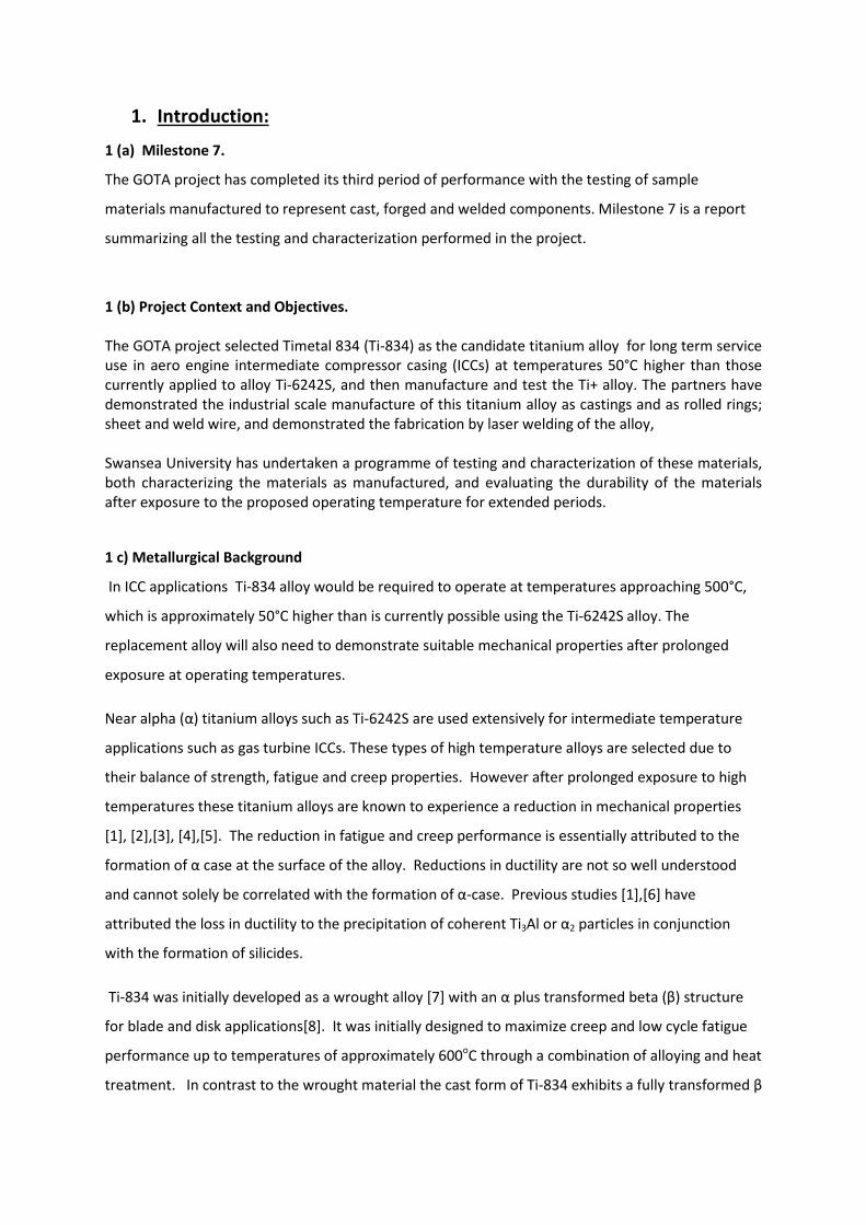
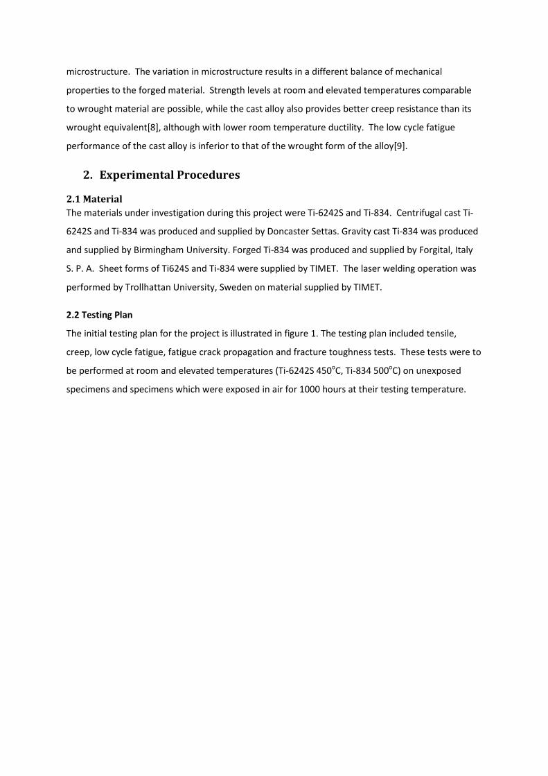
The initial testing plan for the project is illustrated in figure 1. The testing plan included tensile,
creep, low cycle fatigue, fatigue crack propagation and fracture toughness tests. These tests were to
be performed at room and elevated temperatures (Ti-6242S 450oC, Ti-834 500oC) on unexposed
specimens and specimens which were exposed in air for 1000 hours at their testing temperature.

Figure 1 Initial GOTA testing plan
MATERIAL TYPE Macro Micro EBSD
RTT, after 1000hrs
HT @450oC, RTT
RTT post 1000hrs
@500oC.
ETT @ 500oC
ETT @ 450oC
ETT @450C after
1000hrs HT at 450C
ETT 500oC post
1000hrs @500oC.
Creep two different
loads, 500oC
Creep two
different loads, 450oC
Creep, two
different loads, 500C, after
1000hrs HT
@500C LCF RTLCF
450oCLCF
500oC
LCF RT, after
1000hrs HT
@500C
LCF 500C, after
1000hrs HT
@500CFCP RT (R=0.1)
FCP 500oC (R=0.1)
Fracture Toughness
FCP 450oC (R=0.1)
Ti+ Rings: Ring 5: SHTA 2 4 1 0 2 2 2 0 0 2 4 0 4 6 0 6 6 6 1 1 2Ti+ Rings: Ring 4: SHTA 1 2 1 0 2 1 1 0 0 1 0 0 0 0 0 0 0 0 0 0 0Ti+ Rings: Ring 3: SHTA 1 2 1 0 2 1 1 0 0 1 0 0 0 0 0 0 0 0 0 0 0
Ti 6242S CentCast+HIP+SHTA: 1.8 - 2.0mm 1 2 0 2 2 0 0 2 2 0 0 4 0 0 0 0 0 0 1 1 0 1Ti 6242S CentriCast+HIP+SHTA: 8 - 10mm 1 1 0 1 1 0 0 1 1 0 0 0 0 6 6 0 0 0 1 1 0 1Ti 6242S Centricast+HIP+SHTA: 20 - 22mm 1 1 0 1 1 0 0 1 1 0 0 0 0 0 0 0 0 0 1 1 0 1Ti 6242S CentCast+HIP+SHTA: 25 - 35mm 1 2 0 2 2 0 0 2 2 0 0 4 0 6 6 0 0 0 1 1 2 1
Ti + Heat One, As CentCast + SHTA: 8 - 10mm 0 0 0 0 0 0 0 0 0 0 0 0 0 0 0 0 0 0 0 0 0Ti + Heat One, As CentCast + SHTA: 25 - 35mm 0 0 0 0 0 0 0 0 0 0 0 0 0 0 0 0 0 0 0 0 0
Ti + Heat Three, As GravCast + SHTA: 8 - 10mm 0 0 0 0 0 0 0 0 0 0 0 0 0 0 0 0 0 0 0 0 0Ti + Heat Three, As GravCast + SHTA: 25 - 35mm 0 0 0 0 0 0 0 0 0 0 0 0 0 0 0 0 0 0 0 0 0
Ti + Heat One, CentCast+HIP+ SHTA: 1.8 - 2.0mm 1 2 0 0 2 2 2 0 0 2 4 0 4 2 0 2 0 0 1 1 0Ti + Heat One, CentCast+HIP+SHTA: 8 - 10mm 1 1 0 0 1 1 1 0 0 1 1 0 1 4 0 4 0 0 1 1 0Ti+ Heat One, CentCast+HIP+SHTA:20 - 22mm 1 1 0 0 1 1 1 0 0 1 1 0 1 2 0 2 0 0 1 1 0Ti + Heat One, CentCast+HIP+SHTA: 25 - 35mm 1 2 0 0 2 2 2 0 0 2 4 0 4 4 0 4 6 6 1 1 2
Ti + Heat Two, CentCast+HIP+SHTA: 1.8 - 2.0mm 1 2 0 0 1 1 1 0 0 1 0 0 0 0 0 0 0 0 0 0 0Ti + Heat Two, CentCast+HIP+SHTA: 8 - 10mm 1 1 0 0 1 0 1 0 0 0 0 0 0 0 0 0 0 0 0 0 0
Ti + Heat Two, CentCast+HIP+SHTA: 20 - 22mm 1 1 0 0 1 0 1 0 0 0 0 0 0 0 0 0 0 0 0 0 0Ti + Heat Two, CentCast+HIP+SHTA: 25 - 35mm 1 2 0 0 1 1 1 0 0 1 0 0 0 0 0 0 0 0 0 0 0
Ti + Heat Three, GravCast+HIP+SHTA: 1.8 - 2.0mm 1 2 0 0 2 2 2 0 0 2 2 0 0 2 0 2 0 0 1 1 0Ti+ Heat Three, GravCast+HIP+SHTA: 8 - 10mm 1 2 0 0 1 1 1 0 0 1 0 0 0 4 0 4 0 0 1 1 0Ti+ Heat Three, GravCast+HIP+SHTA: 20 - 22mm 1 2 0 0 1 1 1 0 0 1 0 0 0 2 0 2 0 0 1 1 0Ti+ Heat Three, GravCast+HIP+SHTA: 25 - 35mm 1 2 0 0 2 2 2 0 0 2 2 0 0 4 0 4 6 6 1 1 2
Ti + Heat One, CentCast: 25 - 35mm:HIP+SHTA + Repair + SHTA 1 2 0 0 2 2 2 0 0 2 4 0 0 4 0 4 0 0 1 1 0Ti + Heat One, CentCast: 25 - 35mm:HIP+SHTA + [Repair + SHTA] x4 1 2 0 0 2 2 2 0 0 2 4 0 0 4 0 4 0 0 1 1 2
Ti 6242S Sheet: 2mm 0 2 1 2 2 0 0 2 2 0 0 4 0 4 4 0 0 0 1 0 0 1Ti 6242S Sheet: 4mm 0 2 1 2 2 0 0 2 2 0 0 4 0 4 4 0 0 0 1 0 0 1
Ti+ Heat Seven:Sheet: 2.0mm 0 2 1 0 2 2 2 0 0 2 4 0 0 4 0 4 0 0 1 1 0Ti+ Heat Seven: Sheet: 4.0mm 0 2 1 0 2 2 2 0 0 2 4 0 0 4 0 4 0 0 1 1 0
Ti+ Weld wire: 2.0mm 0 1 0 0 0 0 0 0 0 0 0 0 0 0 0 0 0 0 0 0 0
Ti+ / Ti+ welds sheet to sheet; 2mm S/R 1 2 0 0 2 2 2 0 0 2 4 0 0 4 0 4 0 0 1 1 0Ti+ / Ti+ welds sheet to sheet; 4mm, S/R 1 2 0 0 2 2 2 0 0 2 4 0 0 4 0 4 0 0 1 1 0
Ti+ sheet / Ti+ cast 2mm [Preferred casting method] 1 2 0 0 2 2 2 0 0 2 4 0 0 4 0 6 0 0 1 1 0
Ti 6242S / Ti+ welds: 2mm, S/R 1 2 0 2 2 0 0 2 2 0 0 4 0 4 4 0 0 0 1 1 0Ti 6242S / Ti+ welds: 4.0mm S/R 1 2 0 2 2 0 0 2 2 0 0 4 0 4 4 0 0 0 1 1 0
test total27 57 7 14 50 32 34 14 14 32 46 24 14 86 28 60 18 18 24 22 10 540
This plan was revised during the project due to concerns that arose with the post exposure ductility
of the Ti-834 cast material. The testing became more focused on the effect of various exposure
times on the tensile ductility of the centrifugally cast Ti-834 material.
To create a benchmark for the testing Ti-6242S was tested in its cast and sheet forms:
• Cast specimens were taken from stock with diameters/thicknesses of 1.8-2mm, 13mm, 20-22mm and 25-35mm.
• Sheet specimens were tested at thicknesses of 2mm and 4mm.
Ti-834 was tested in a number forms:
• Forged condition; where specimens were taken from the circumferential direction of rolled rings.
• Centrifugally cast specimens were taken from stock with diameters/thicknesses of 1.8-2mm, 13mm, 20-22mm and 25-35mm.
• Gravity cast specimens were taken from stock with diameters/thicknesses of 1.8-2mm, 13mm, 20-22mm and 25-35mm.
• Sheet specimens were tested at thicknesses of 2mm and 4mm. • Welded sheet specimens were tested at thicknesses of 2mm and 4mm. • Centrifugally cast material was also tested after undergoing a hydrogen anneal + vacuum
degas (HDH) process intended to refine the microstructure. Specimens were taken from stock with diameters of 13mm and 25-35mm.
2.3 Exposure Exposures were performed in air in a Carbolite CWF 1200 box furnace; these were followed in all
instances by air cooling. All Ti-6242S specimens were exposed at 450oC, while all Ti-834 specimens
were exposed at 500oC. Exposure times of 25, 100, 200, 500 and 1000 hours were employed during
the project.
2.4 Specimens
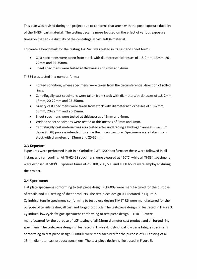
Flat plate specimens conforming to test piece design RLH6009 were manufactured for the purpose
of tensile and LCF testing of sheet products. The test-piece design is illustrated in Figure 2.
Cylindrical tensile specimens conforming to test piece design TIMET R6 were manufactured for the
purpose of tensile testing all cast and forged products. The test-piece design is illustrated in Figure 3.
Cylindrical low cycle fatigue specimens conforming to test piece design RLH10113 were
manufactured for the purpose of LCF testing of all 25mm diameter cast product and all forged ring
specimens. The test-piece design is illustrated in Figure 4. Cylindrical low cycle fatigue specimens
conforming to test piece design RLH8001 were manufactured for the purpose of LCF testing of all
13mm diameter cast product specimens. The test-piece design is illustrated in Figure 5.
Cylindrical creep specimens conforming to test piece design RLH10259 were manufactured for the
purpose of all creep testing. The test-piece design is illustrated in Figure 6.
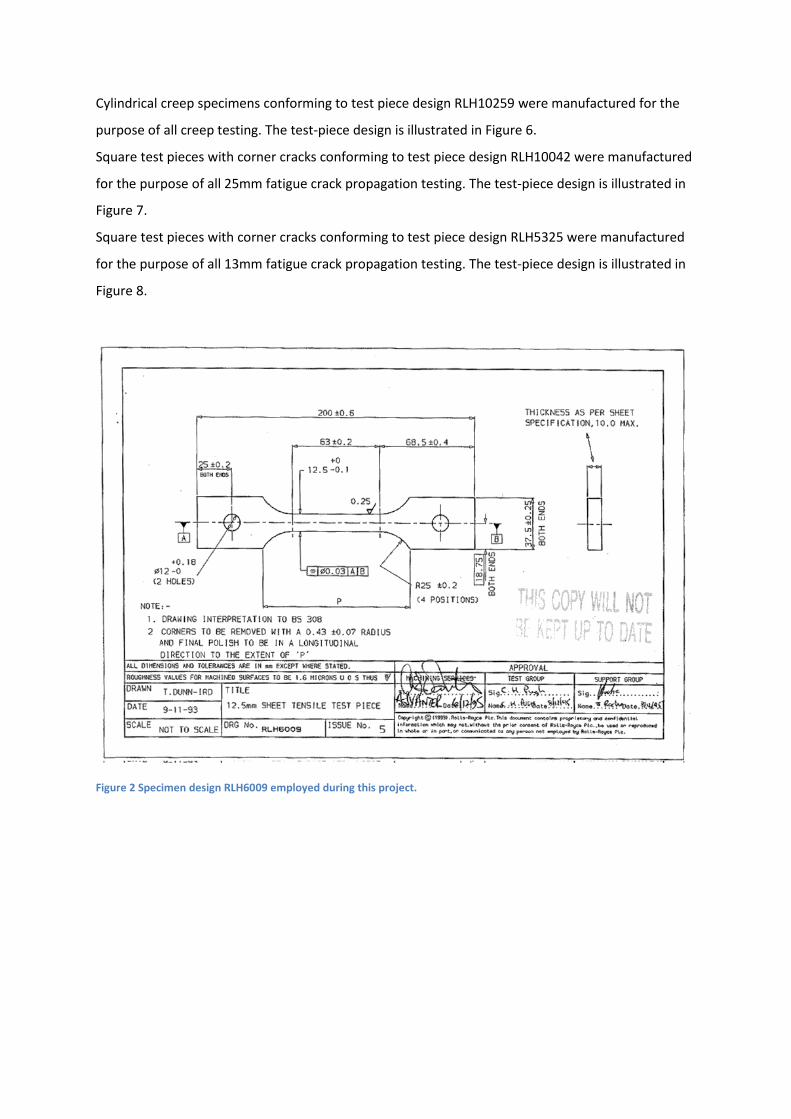
Square test pieces with corner cracks conforming to test piece design RLH10042 were manufactured
for the purpose of all 25mm fatigue crack propagation testing. The test-piece design is illustrated in
Figure 7.
Square test pieces with corner cracks conforming to test piece design RLH5325 were manufactured
for the purpose of all 13mm fatigue crack propagation testing. The test-piece design is illustrated in
Figure 8.
Figure 2 Specimen design RLH6009 employed during this project.

Figure 3 Specimen design TIMET R6 employed during this project.
Figure 4 Specimen design RLH10113 employed during this project.

Figure 5 Specimen design RLH8001 employed during this project.
Figure 6 Specimen design RLH10259 employed during this project.
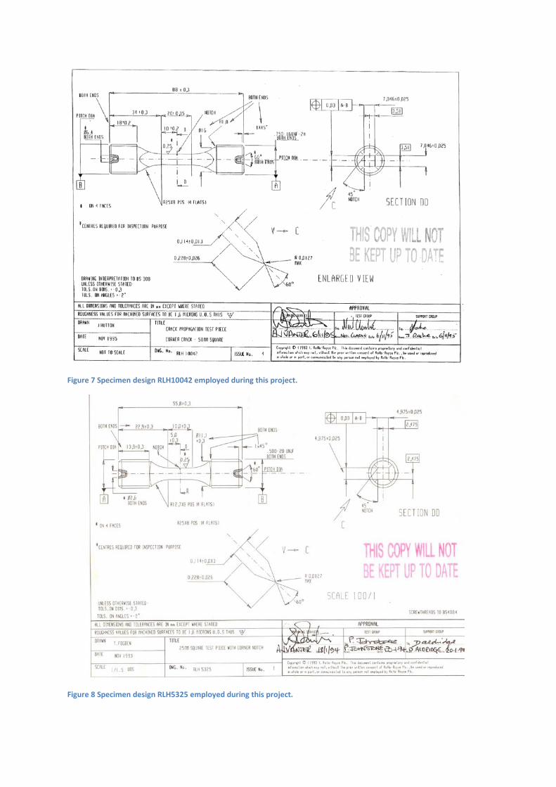
Figure 7 Specimen design RLH10042 employed during this project.
Figure 8 Specimen design RLH5325 employed during this project.

2.5 Test Methods
All tensile tests within this project were carried- out in accordance with the in-house standard test
operating procedure: SMaRT_QS 5.4d(2) STOP_TMM: Test Method and Data Analysis for Tensile
Testing of Metallic Materials. This document adheres to the standards listed in appendix a.
All force controlled LCF tests within this contract were carried-out in accordance with the in-house
standard test operating procedure: SMaRT_QS5.4d (1) STOP Force Controlled Fatigue Testing. This
document adheres to the standards listed in appendix b.
All strain controlled LCF tests within this contract were carried-out in accordance with the in-house
standard test operating procedure: SMaRT_QS5.4d(3) STOP_SLCF Strain Controlled Low Cycle
Fatigue Test Procedures. This document adheres to the standards listed in appendix c.
All creep tests within this project were carried- out in accordance with the in-house standard test
operating procedure: SMaRT_QS5.4d(5) STOP_CLC Constant Load Creep Test Procedure. This
document adheres to the standards listed in appendix d.
All fatigue crack propagation tests within this project were carried- out in accordance with the in-
house standard test operating procedure: SMaRT_QS 5.4d(4) STOP_CCG Fatigue crack growth in
metallic materials - corner crack geometry. Appendix e
2.6 Test Conditions
Tensile testing of Ti-6242S was performed at room temperature and 450oC. Tensile testing of all Ti-
834 products was performed at room temperature and 500oC. Dual strain rates of 0.00005s-1 up until
2% strain and 1mm/min thereafter were employed for the tests.
Load control LCF testing was performed at room and elevated temperatures (450oC Ti-6242S, 500oC
Ti-834). Room temperature tests were performed at loads of 950MPa and 750MPa, at elevated
temperature loads of 750MPa and 650MPa were employed. An R ratio of 0.01 was utilised for all
tests.
Strain control LCF testing was performed at room and elevated temperatures (450oC Ti-6242S, 500oC
Ti-834). Room temperature tests were performed at maximum strains of 1.0% and 0.55% on all cast
products, at elevated temperature maximum strains of 1.2% and 0.65% were employed on all cast
products. Room temperature tests were performed at maximum strains of 1.5% and 0.8% on all

forged products, at elevated temperature maximum strains of 1.5% and 0.9% were employed on all
forged products. An R ratio of 0.01 was applied for all tests.
Creep testing was performed at elevated temperatures of 450oC for Ti-6242S and 500oC for Ti-834
products. Tests were performed at levels between 450MPa and 625MPa during this project.
Fatigue crack propagation tests were performed in load control at room temperature. Room
temperature tests were performed at a peak stress of 520MPa, elevated temperature tests were
performed at a peak stress of 315MPa. A triangular waveform was used for all tests.
3. Results The microstructures of the materials investigated are illustrated in this section:
The centrifugally cast Ti-6242S alloy displayed an equiaxed lamellar microstructure (Figure 9) with an
average prior β grain size of approx. 730µm in diameter. The β grains are surrounded by a
continuous layer of grain boundary alpha several microns in width.
Figure 9 Ti-6242S centrifugally cast alloy
The centrifugally cast Ti-834 alloy also displayed an equiaxed lamellar microstructure (Figure 10)
with an average prior β grain size of approximately 850µm in diameter. The β grains are once again
surrounded by a constant layer of grain boundary alpha several microns in width.

Figure 10 Ti-834 centrifugally cast alloy
The 13mm HDH processed centrifugally cast Ti-834 alloy displayed a finer equiaxed lamellar
microstructure (Figure 11) when compared to the base material, with an average prior β grain size of
approximately 435µm in diameter. The internal structure of these grains illustrated in figure 11b
contrasted with the base material; displaying a Widmanstatten type structure compared to the
coarse alpha lath structure of the base alloy. The β grains are once again surrounded by a
continuous layer of grain boundary alpha several microns in width.
Figure 11 Ti-834 13mm hydrogenated centrifugally cast alloy
The 23mm HDH centrifugally cast Ti834 alloy displayed a coarser equiaxed lamellar microstructure
(Figure 12) when compared to the 13mm material, with an average prior β grain size of
approximately 700µm in diameter. The internal structure of these grains illustrated in figure 12b
also displayed a Widmanstatten type structure. The β grains are once again surrounded by a
continuous layer of grain boundary alpha several microns in width.
a b

Figure 12 Ti-834 13mm hydrogenated centrifugally cast alloy
The gravity cast Ti-834 alloy as expected also displayed an equiaxed lamellar microstructure (Figure
13), the material had a very large grain size with an average prior β grain size approximately 2176µm
in diameter. The β grains are once again surrounded by a layer of grain boundary α.
Figure 13 Ti-834 gravity cast alloy
The forged Ti-834 alloy displayed an equiaxed bimodal microstructure (Figure 14) with an average
primary alpha grain size approximately 20µm in diameter.
a b
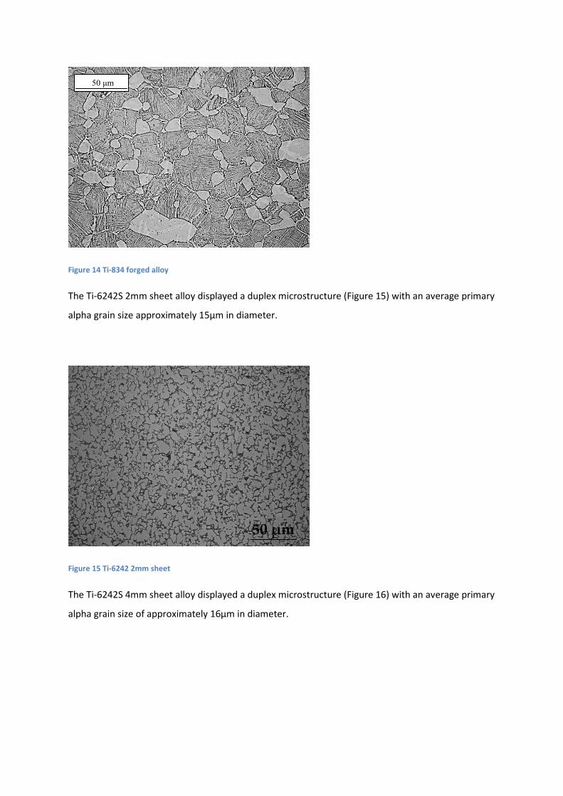
Figure 14 Ti-834 forged alloy
The Ti-6242S 2mm sheet alloy displayed a duplex microstructure (Figure 15) with an average primary
alpha grain size approximately 15µm in diameter.
Figure 15 Ti-6242 2mm sheet
The Ti-6242S 4mm sheet alloy displayed a duplex microstructure (Figure 16) with an average primary
alpha grain size of approximately 16µm in diameter.
50 μm

Figure 16 Ti-6242 4mm sheet
The Ti-834 2mm sheet alloy displayed ae bimodal microstructure (Figure 17) with an average
primary alpha grain size of approximately 18µm in diameter.
Figure 17 Ti-834 2mm sheet
The Ti-834 4mm sheet alloy displayed a bimodal microstructure (Figure 18) with an average primary
alpha grain size of approximately 20µm in diameter.
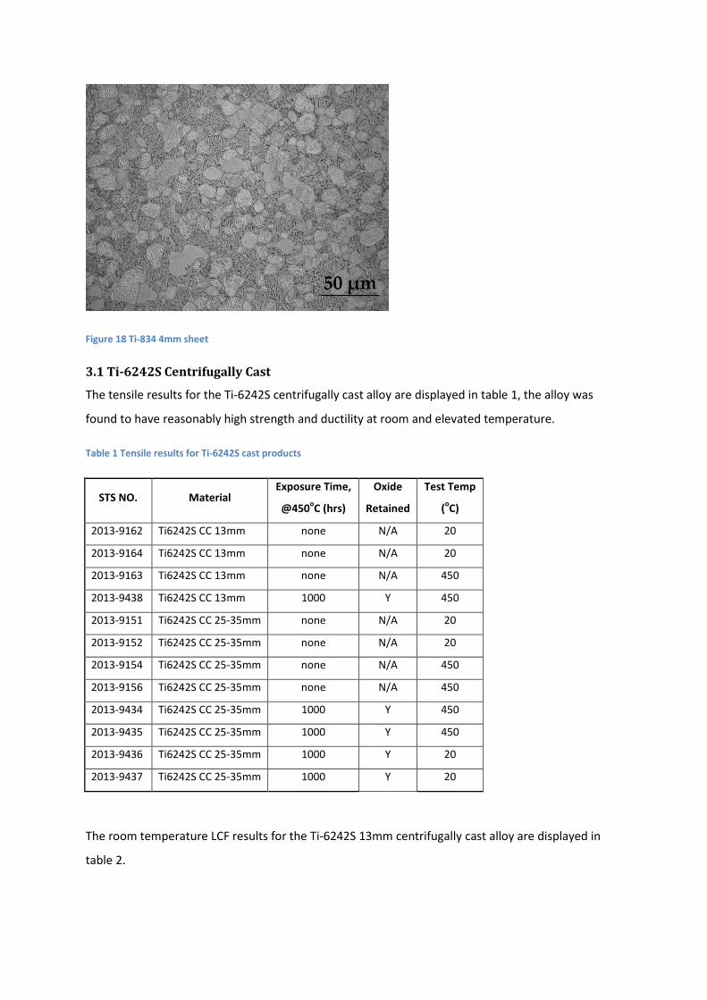
Figure 18 Ti-834 4mm sheet
3.1 Ti-6242S Centrifugally Cast
The tensile results for the Ti-6242S centrifugally cast alloy are displayed in table 1, the alloy was
found to have reasonably high strength and ductility at room and elevated temperature.
Table 1 Tensile results for Ti-6242S cast products
STS NO. Material Exposure Time,
@450oC (hrs)
Oxide
Retained
Test Temp
(oC)
2013-9162 Ti6242S CC 13mm none N/A 20
2013-9164 Ti6242S CC 13mm none N/A 20
2013-9163 Ti6242S CC 13mm none N/A 450
2013-9438 Ti6242S CC 13mm 1000 Y 450
2013-9151 Ti6242S CC 25-35mm none N/A 20
2013-9152 Ti6242S CC 25-35mm none N/A 20
2013-9154 Ti6242S CC 25-35mm none N/A 450
2013-9156 Ti6242S CC 25-35mm none N/A 450
2013-9434 Ti6242S CC 25-35mm 1000 Y 450
2013-9435 Ti6242S CC 25-35mm 1000 Y 450
2013-9436 Ti6242S CC 25-35mm 1000 Y 20
2013-9437 Ti6242S CC 25-35mm 1000 Y 20
The room temperature LCF results for the Ti-6242S 13mm centrifugally cast alloy are displayed in
table 2.
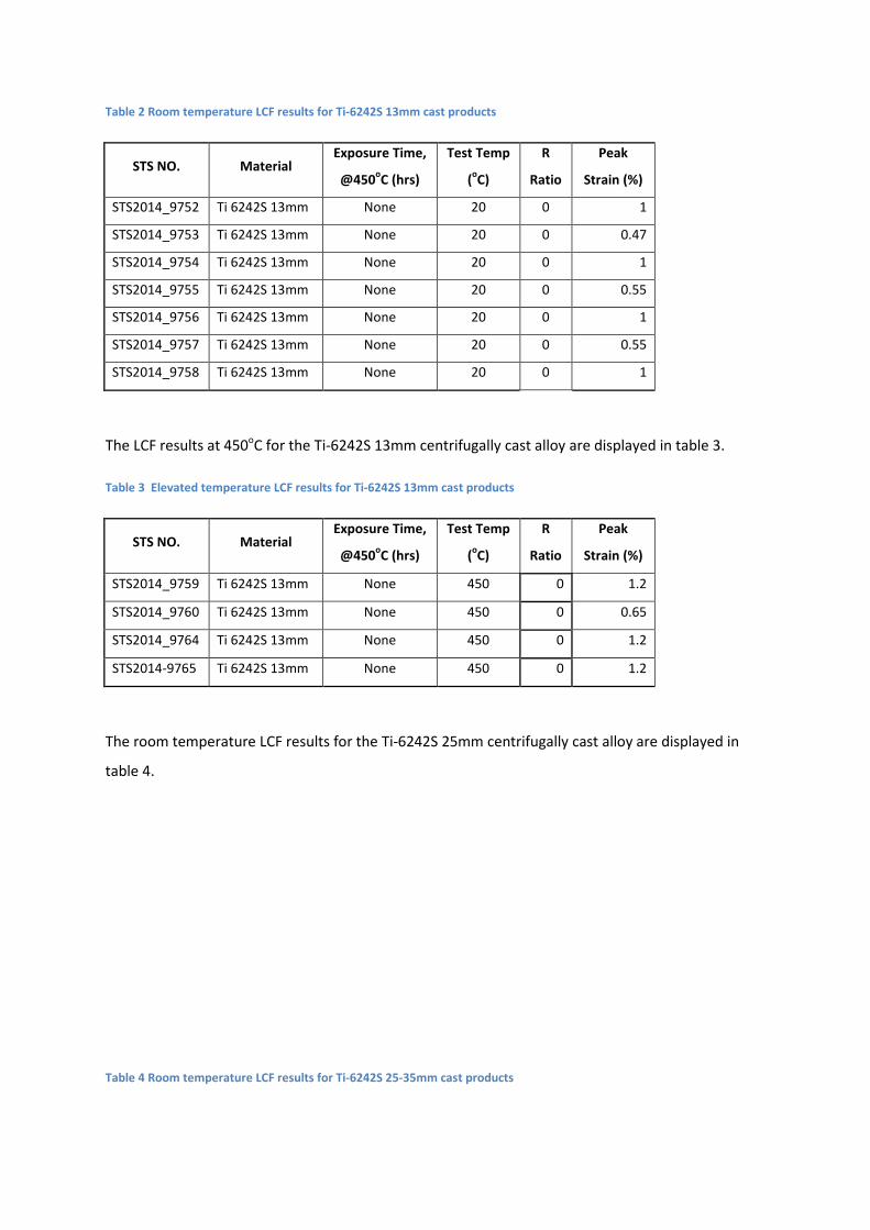
Table 2 Room temperature LCF results for Ti-6242S 13mm cast products
STS NO. Material Exposure Time,
@450oC (hrs)
Test Temp
(oC)
R
Ratio
Peak
Strain (%)
STS2014_9752 Ti 6242S 13mm None 20 0 1
STS2014_9753 Ti 6242S 13mm None 20 0 0.47
STS2014_9754 Ti 6242S 13mm None 20 0 1
STS2014_9755 Ti 6242S 13mm None 20 0 0.55
STS2014_9756 Ti 6242S 13mm None 20 0 1
STS2014_9757 Ti 6242S 13mm None 20 0 0.55
STS2014_9758 Ti 6242S 13mm None 20 0 1
The LCF results at 450oC for the Ti-6242S 13mm centrifugally cast alloy are displayed in table 3.
Table 3 Elevated temperature LCF results for Ti-6242S 13mm cast products
STS NO. Material Exposure Time,
@450oC (hrs)
Test Temp
(oC)
R
Ratio
Peak
Strain (%)
STS2014_9759 Ti 6242S 13mm None 450 0 1.2
STS2014_9760 Ti 6242S 13mm None 450 0 0.65
STS2014_9764 Ti 6242S 13mm None 450 0 1.2
STS2014-9765 Ti 6242S 13mm None 450 0 1.2
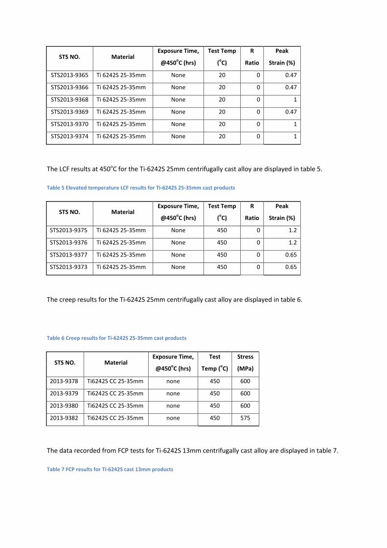
The room temperature LCF results for the Ti-6242S 25mm centrifugally cast alloy are displayed in
table 4.
Table 4 Room temperature LCF results for Ti-6242S 25-35mm cast products
STS NO. Material Exposure Time,
@450oC (hrs)
Test Temp
(oC)
R
Ratio
Peak
Strain (%)
STS2013-9365 Ti 6242S 25-35mm None 20 0 0.47
STS2013-9366 Ti 6242S 25-35mm None 20 0 0.47
STS2013-9368 Ti 6242S 25-35mm None 20 0 1
STS2013-9369 Ti 6242S 25-35mm None 20 0 0.47
STS2013-9370 Ti 6242S 25-35mm None 20 0 1
STS2013-9374 Ti 6242S 25-35mm None 20 0 1
The LCF results at 450oC for the Ti-6242S 25mm centrifugally cast alloy are displayed in table 5.
Table 5 Elevated temperature LCF results for Ti-6242S 25-35mm cast products
STS NO. Material Exposure Time,
@450oC (hrs)
Test Temp
(oC)
R
Ratio
Peak
Strain (%)
STS2013-9375 Ti 6242S 25-35mm None 450 0 1.2
STS2013-9376 Ti 6242S 25-35mm None 450 0 1.2
STS2013-9377 Ti 6242S 25-35mm None 450 0 0.65
STS2013-9373 Ti 6242S 25-35mm None 450 0 0.65
The creep results for the Ti-6242S 25mm centrifugally cast alloy are displayed in table 6.
Table 6 Creep results for Ti-6242S 25-35mm cast products
STS NO. Material Exposure Time,
@450oC (hrs)
Test
Temp (oC)
Stress
(MPa)
2013-9378 Ti6242S CC 25-35mm none 450 600
2013-9379 Ti6242S CC 25-35mm none 450 600
2013-9380 Ti6242S CC 25-35mm none 450 600
2013-9382 Ti6242S CC 25-35mm none 450 575
The data recorded from FCP tests for Ti-6242S 13mm centrifugally cast alloy are displayed in table 7.
Table 7 FCP results for Ti-6242S cast 13mm products
STS NO. Material Exposure
Time, @450oC
(hrs)
Test Temp
(oC)
Stress (MPa)
2014-9506 Ti6242S CC
13mm
none 20 520
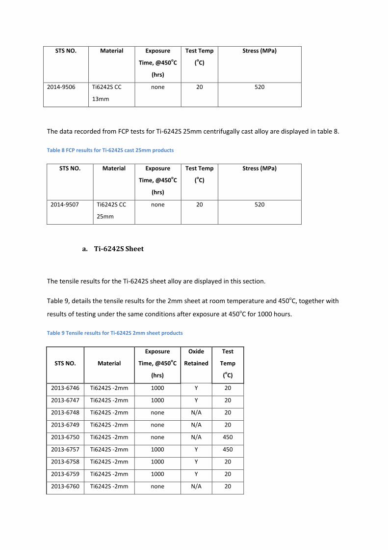
The data recorded from FCP tests for Ti-6242S 25mm centrifugally cast alloy are displayed in table 8.
Table 8 FCP results for Ti-6242S cast 25mm products
STS NO. Material Exposure
Time, @450oC
(hrs)
Test Temp
(oC)
Stress (MPa)
2014-9507 Ti6242S CC
25mm
none 20 520
a. Ti-6242S Sheet
The tensile results for the Ti-6242S sheet alloy are displayed in this section.
Table 9, details the tensile results for the 2mm sheet at room temperature and 450oC, together with
results of testing under the same conditions after exposure at 450oC for 1000 hours.
Table 9 Tensile results for Ti-6242S 2mm sheet products
STS NO. Material
Exposure
Time, @450oC
(hrs)
Oxide
Retained
Test
Temp
(oC)
2013-6746 Ti6242S -2mm 1000 Y 20
2013-6747 Ti6242S -2mm 1000 Y 20
2013-6748 Ti6242S -2mm none N/A 20
2013-6749 Ti6242S -2mm none N/A 20
2013-6750 Ti6242S -2mm none N/A 450
2013-6757 Ti6242S -2mm 1000 Y 450
2013-6758 Ti6242S -2mm 1000 Y 20
2013-6759 Ti6242S -2mm 1000 Y 20
2013-6760 Ti6242S -2mm none N/A 20

2013-6761 Ti6242S -2mm none N/A 20
2013-6762 Ti6242S -2mm none N/A 450
2013-6763 Ti6242S -2mm 1000 Y 450
The tensile results at room and elevated temperature for the 4mm sheet variant are shown in table
10, together with further tensile tests after exposure at 450oC for 100 hours.
Table 10 Tensile results for Ti-6242S 4mm sheet products
STS NO. Material
Exposure
Time,
@450oC (hrs)
Oxide
Retained
Test
Temp
(oC)
2015-12371 Ti6242S -4mm 100 Y 20
2015-12372 Ti6242S -4mm None N/A 20
2015-12377 Ti6242S -4mm None N/A 450
2015-12379 Ti6242S -4mm None N/A 20
2015-12380 Ti6242S -4mm 100 Y 20
2015-12383 Ti6242S -4mm None N/A 20
The room temperature LCF results for the Ti-6242S 2mm sheet alloy are displayed in table 11. Lower
stress levels of 750MPa resulted in long lives with both specimens.
Table 11 Room temperature LCF results for Ti-6242S 2mm sheet products
STS NO. Material Exposure Time,
@450oC (hrs)
Test Temp
(oC)
R
Ratio
Stress
(MPa)
2013-6751 Ti6242S -2mm None 20 0.01 950
2013-6756 Ti6242S -2mm None 20 0.01 750
2013-6765 Ti6242S -2mm None 20 0.01 950
2013-6766 Ti6242S -2mm None 20 0.01 750
The elevated temperature LCF results for the Ti-6242S 2mm sheet alloy are illustrated in table 12.
Table 12 Elevated temperature LCF results for Ti-6242S 2mm sheet products
STS NO. Material Exposure Time,
@450oC (hrs)
Test Temp
(oC)
R
Ratio
Stress
(MPa)
2013-6754 Ti6242S -2mm None 450 0.01 750
2013-6755 Ti6242S -2mm None 450 0.01 750
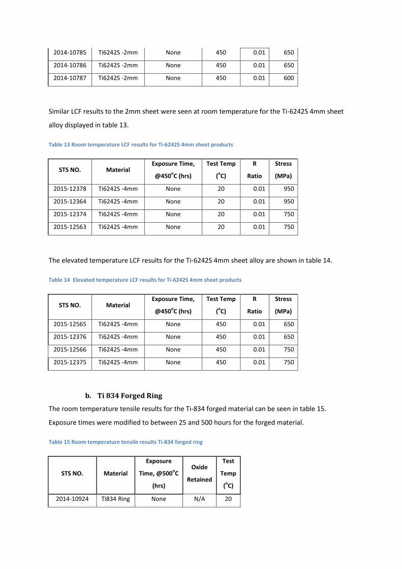
2014-10785 Ti6242S -2mm None 450 0.01 650
2014-10786 Ti6242S -2mm None 450 0.01 650
2014-10787 Ti6242S -2mm None 450 0.01 600
Similar LCF results to the 2mm sheet were seen at room temperature for the Ti-6242S 4mm sheet
alloy displayed in table 13.
Table 13 Room temperature LCF results for Ti-6242S 4mm sheet products
STS NO. Material Exposure Time,
@450oC (hrs)
Test Temp
(oC)
R
Ratio
Stress
(MPa)
2015-12378 Ti6242S -4mm None 20 0.01 950
2015-12364 Ti6242S -4mm None 20 0.01 950
2015-12374 Ti6242S -4mm None 20 0.01 750
2015-12563 Ti6242S -4mm None 20 0.01 750
The elevated temperature LCF results for the Ti-6242S 4mm sheet alloy are shown in table 14.
Table 14 Elevated temperature LCF results for Ti-6242S 4mm sheet products
STS NO. Material Exposure Time,
@450oC (hrs)
Test Temp
(oC)
R
Ratio
Stress
(MPa)
2015-12565 Ti6242S -4mm None 450 0.01 650
2015-12376 Ti6242S -4mm None 450 0.01 650
2015-12566 Ti6242S -4mm None 450 0.01 750
2015-12375 Ti6242S -4mm None 450 0.01 750
b. Ti 834 Forged Ring
The room temperature tensile results for the Ti-834 forged material can be seen in table 15.
Exposure times were modified to between 25 and 500 hours for the forged material.
Table 15 Room temperature tensile results Ti-834 forged ring
STS NO. Material
Exposure
Time, @500oC
(hrs)
Oxide
Retained
Test
Temp
(oC)
2014-10924 Ti834 Ring None N/A 20
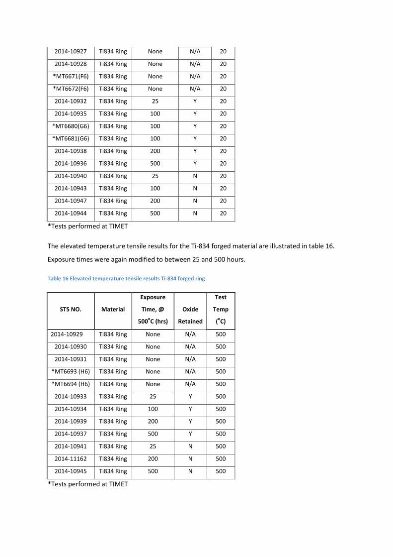
2014-10927 Ti834 Ring None N/A 20
2014-10928 Ti834 Ring None N/A 20
*MT6671(F6) Ti834 Ring None N/A 20
*MT6672(F6) Ti834 Ring None N/A 20
2014-10932 Ti834 Ring 25 Y 20
2014-10935 Ti834 Ring 100 Y 20
*MT6680(G6) Ti834 Ring 100 Y 20
*MT6681(G6) Ti834 Ring 100 Y 20
2014-10938 Ti834 Ring 200 Y 20
2014-10936 Ti834 Ring 500 Y 20
2014-10940 Ti834 Ring 25 N 20
2014-10943 Ti834 Ring 100 N 20
2014-10947 Ti834 Ring 200 N 20
2014-10944 Ti834 Ring 500 N 20
*Tests performed at TIMET
The elevated temperature tensile results for the Ti-834 forged material are illustrated in table 16.
Exposure times were again modified to between 25 and 500 hours.
Table 16 Elevated temperature tensile results Ti-834 forged ring
STS NO. Material
Exposure
Time, @
500oC (hrs)
Oxide
Retained
Test
Temp
(oC)
2014-10929 Ti834 Ring None N/A 500
2014-10930 Ti834 Ring None N/A 500
2014-10931 Ti834 Ring None N/A 500
*MT6693 (H6) Ti834 Ring None N/A 500
*MT6694 (H6) Ti834 Ring None N/A 500
2014-10933 Ti834 Ring 25 Y 500
2014-10934 Ti834 Ring 100 Y 500
2014-10939 Ti834 Ring 200 Y 500
2014-10937 Ti834 Ring 500 Y 500
2014-10941 Ti834 Ring 25 N 500
2014-11162 Ti834 Ring 200 N 500
2014-10945 Ti834 Ring 500 N 500
*Tests performed at TIMET
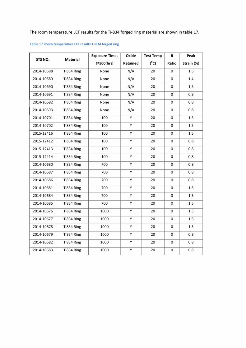
The room temperature LCF results for the Ti-834 forged ring material are shown in table 17.
Table 17 Room temperature LCF results Ti-834 forged ring
STS NO. Material Exposure Time,
@500(hrs)
Oxide
Retained
Test Temp
(oC)
R
Ratio
Peak
Strain (%)
2014-10688 Ti834 Ring None N/A 20 0 1.5
2014-10689 Ti834 Ring None N/A 20 0 1.4
2014-10690 Ti834 Ring None N/A 20 0 1.5
2014-10691 Ti834 Ring None N/A 20 0 0.8
2014-10692 Ti834 Ring None N/A 20 0 0.8
2014-10693 Ti834 Ring None N/A 20 0 0.8
2014-10701 Ti834 Ring 100 Y 20 0 1.5
2014-10702 Ti834 Ring 100 Y 20 0 1.5
2015-12416 Ti834 Ring 100 Y 20 0 1.5
2015-12412 Ti834 Ring 100 Y 20 0 0.8
2015-12413 Ti834 Ring 100 Y 20 0 0.8
2015-12414 Ti834 Ring 100 Y 20 0 0.8
2014-10680 Ti834 Ring 700 Y 20 0 0.8
2014-10687 Ti834 Ring 700 Y 20 0 0.8
2014-10686 Ti834 Ring 700 Y 20 0 0.8
2014-10681 Ti834 Ring 700 Y 20 0 1.5
2014-10684 Ti834 Ring 700 Y 20 0 1.5
2014-10685 Ti834 Ring 700 Y 20 0 1.5
2014-10676 Ti834 Ring 1000 Y 20 0 1.5
2014-10677 Ti834 Ring 1000 Y 20 0 1.5
2014-10678 Ti834 Ring 1000 Y 20 0 1.5
2014-10679 Ti834 Ring 1000 Y 20 0 0.8
2014-10682 Ti834 Ring 1000 Y 20 0 0.8
2014-10683 Ti834 Ring 1000 Y 20 0 0.8

The elevated temperature LCF results for the Ti-834 forged material are displayed in table 18.
Table 18 Elevated temperature LCF results Ti-834 forged ring
STS NO. Material Exposure Time,
@500(hrs)
Test Temp
(oC)
R
Ratio
Peak
Strain (%)
2014-10694 Ti834 Ring None 500 0 1.5
2014-10695 Ti834 Ring None 500 0 1.5
2014-10696 Ti834 Ring None 500 0 1.5
2014-10698 Ti834 Ring None 500 0 0.9
2014-10699 Ti834 Ring None 500 0 0.9
2015-12417 Ti834 Ring 100 500 0 1.5
2015-12419 Ti834 Ring 100 500 0 1.5
2015-12418 Ti834 Ring 100 500 0 0.9
2015-12420 Ti834 Ring 100 500 0 0.9
Creep results for the Ti-834 forged alloy are displayed in table 19. Time taken to 0.5% creep strain
was reasonably consistent with 3 of the results.
Table 19 Creep results Ti-834 forged ring
STS NO. Material
Exposure
Time, @
500 (hrs)
Test
Temp
(oC)
Stress
(MPa)
2014-11066 Ti834 Ring None 500 600
2014-11067 Ti834 Ring None 500 600
2014-11068 Ti834 Ring None 500 625
2014-11069 Ti834 Ring None 500 625
*N6/3B/1B Ti834 Ring None 500 600
*N6/3B/1C Ti834 Ring None 500 600
*P6/3B/2B Ti834 Ring 100 500 600
*P6/3B/2C Ti834 Ring 100 500 600
*Tests performed at TIMET

The data recorded from FCP tests for Ti-834 forged alloy are shown in table 20.
Table 20 FCP results for Ti-834 forged ring
STS NO. Material Exposure
Time, @450oC
(hrs)
Test Temp
(oC)
Stress (MPa)
2014-10703 Ti834 Ring none 20 520
c. Centrifugally Cast Ti-834
The room temperature tensile results for the Ti-834 centrifugally cast alloy are shown in table 21.
Reasonably high strength levels and good ductility levels were recorded for the unexposed material
at room temperature. As with the forged alloy exposure times were modified to between 25 and 500
hours. The various exposure times were not found to have a significant effect on the strength of the
material but significant reductions in tensile ductility were recorded in line with increasing exposure
times when the oxide layer was retained. When this oxide layer was removed for testing some of
the previously lost ductility was recovered for the longer exposure times.
Table 21 Room temperature tensile results centrifugally cast Ti-834
STS NO. Material
Exposure
@ 500oC
(hrs)
Oxide
Retained
Test
Temp
(oC)
2014-10901 Ti834 CC25mm None N/A 20
2014-10902 Ti834 CC25mm None N/A 20
2014-10903 Ti834 CC25mm None N/A 20
*MT6677(F14) Ti834 CC13mm None N/A 20
*MT6678 (F15) Ti834 CC22mm None N/A 20
*MT6678 (F20) Ti834 CC25mm None N/A 20
*MT6673 (F9) Ti834 CC13mm None N/A 20
*MT6674 (F9) Ti834 CC13mm None N/A 20
*MT6675 (F11) Ti834 CC25mm None N/A 20
*MT6676 (F11) Ti834 CC25mm None N/A 20
2014-10907 Ti834 CC25mm 500 Y 20
2014-10908 Ti834 CC25mm 500 Y 20
2014-10909 Ti834 CC25mm 500 Y 20
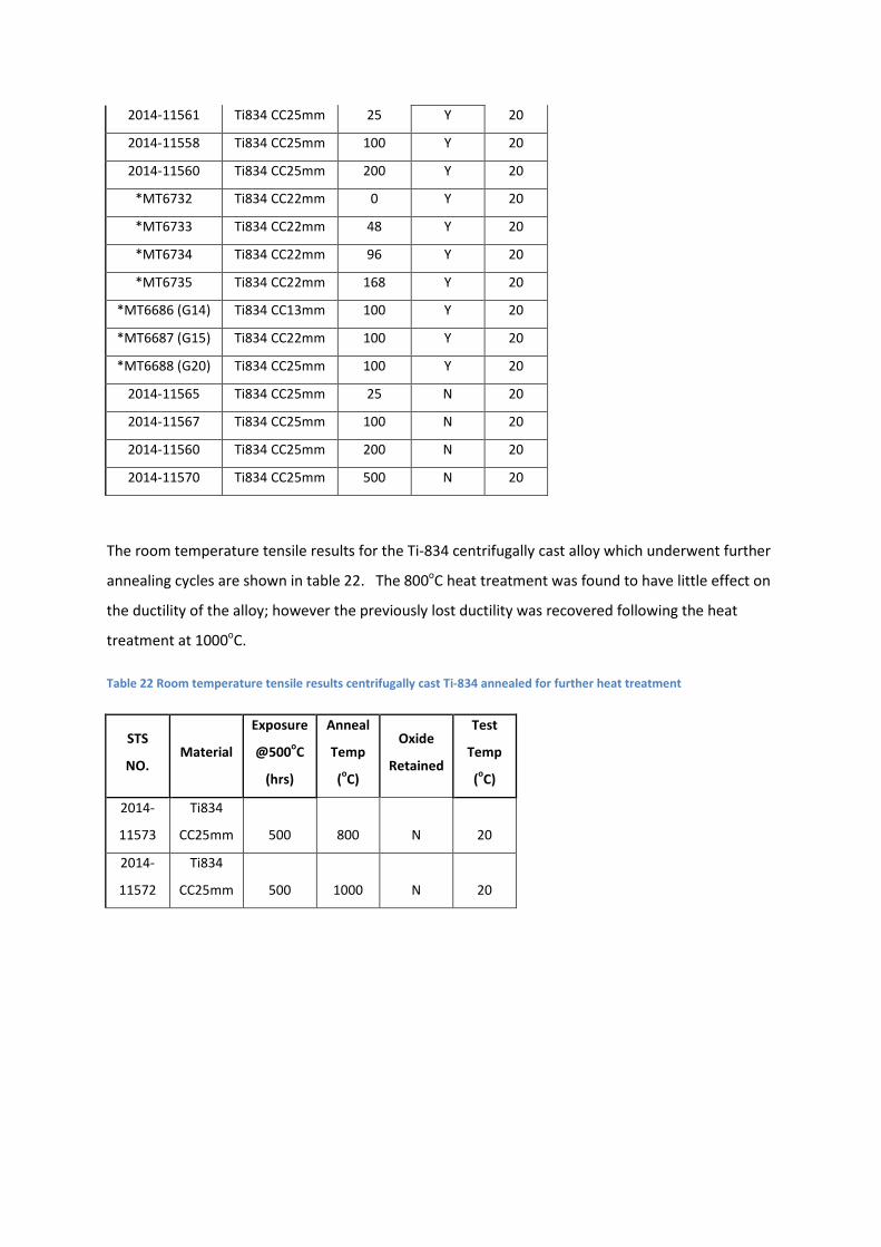
2014-11561 Ti834 CC25mm 25 Y 20
2014-11558 Ti834 CC25mm 100 Y 20
2014-11560 Ti834 CC25mm 200 Y 20
*MT6732 Ti834 CC22mm 0 Y 20
*MT6733 Ti834 CC22mm 48 Y 20
*MT6734 Ti834 CC22mm 96 Y 20
*MT6735 Ti834 CC22mm 168 Y 20
*MT6686 (G14) Ti834 CC13mm 100 Y 20
*MT6687 (G15) Ti834 CC22mm 100 Y 20
*MT6688 (G20) Ti834 CC25mm 100 Y 20
2014-11565 Ti834 CC25mm 25 N 20
2014-11567 Ti834 CC25mm 100 N 20
2014-11560 Ti834 CC25mm 200 N 20
2014-11570 Ti834 CC25mm 500 N 20
The room temperature tensile results for the Ti-834 centrifugally cast alloy which underwent further
annealing cycles are shown in table 22. The 800oC heat treatment was found to have little effect on
the ductility of the alloy; however the previously lost ductility was recovered following the heat
treatment at 1000oC.
Table 22 Room temperature tensile results centrifugally cast Ti-834 annealed for further heat treatment
STS
NO. Material
Exposure
@500oC
(hrs)
Anneal
Temp
(oC)
Oxide
Retained
Test
Temp
(oC)
2014-
11573
Ti834
CC25mm 500 800 N 20
2014-
11572
Ti834
CC25mm 500 1000 N 20
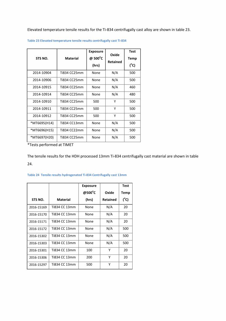
Elevated temperature tensile results for the Ti-834 centrifugally cast alloy are shown in table 23.
Table 23 Elevated temperature tensile results centrifugally cast Ti-834
STS NO. Material
Exposure
@ 500oC
(hrs)
Oxide
Retained
Test
Temp
(oC)
2014-10904 Ti834 CC25mm None N/A 500
2014-10906 Ti834 CC25mm None N/A 500
2014-10915 Ti834 CC25mm None N/A 460
2014-10914 Ti834 CC25mm None N/A 480
2014-10910 Ti834 CC25mm 500 Y 500
2014-10911 Ti834 CC25mm 500 Y 500
2014-10912 Ti834 CC25mm 500 Y 500
*MT6695(H14) Ti834 CC13mm None N/A 500
*MT6696(H15) Ti834 CC22mm None N/A 500
*MT6697(H20) Ti834 CC25mm None N/A 500
*Tests performed at TIMET
The tensile results for the HDH processed 13mm Ti-834 centrifugally cast material are shown in table
24.
Table 24 Tensile results hydrogenated Ti-834 Centrifugally cast 13mm
STS NO. Material
Exposure
@500oC
(hrs)
Oxide
Retained
Test
Temp
(oC)
2016-15169 Ti834 CC 13mm None N/A 20
2016-15170 Ti834 CC 13mm None N/A 20
2016-15171 Ti834 CC 13mm None N/A 20
2016-15172 Ti834 CC 13mm None N/A 500
2016-15302 Ti834 CC 13mm None N/A 500
2016-15303 Ti834 CC 13mm None N/A 500
2016-15301 Ti834 CC 13mm 100 Y 20
2016-15306 Ti834 CC 13mm 200 Y 20
2016-15297 Ti834 CC 13mm 500 Y 20
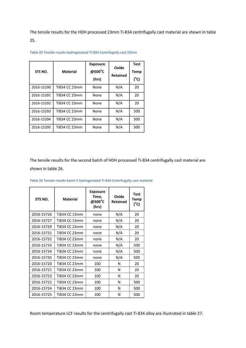
The tensile results for the HDH processed 23mm Ti-834 centrifugally cast material are shown in table
25.
Table 25 Tensile results hydrogenated Ti-834 Centrifugally cast 23mm
STS NO. Material
Exposure
@500oC
(hrs)
Oxide
Retained
Test
Temp
(oC)
2016-15290 Ti834 CC 23mm None N/A 20
2016-15291 Ti834 CC 23mm None N/A 20
2016-15292 Ti834 CC 23mm None N/A 20
2016-15293 Ti834 CC 23mm None N/A 500
2016-15294 Ti834 CC 23mm None N/A 500
2016-15295 Ti834 CC 23mm None N/A 500
The tensile results for the second batch of HDH processed Ti-834 centrifugally cast material are
shown in table 26.
Table 26 Tensile results batch 2 hydrogenated Ti-834 Centrifugally cast material
STS NO. Material
Exposure Time,
@500oC (hrs)
Oxide Retained
Test Temp (oC)
2016-15726 Ti834 CC 13mm none N/A 20 2016-15727 Ti834 CC 13mm none N/A 20 2016-15729 Ti834 CC 23mm none N/A 20 2016-15731 Ti834 CC 23mm none N/A 20 2016-15732 Ti834 CC 23mm none N/A 20 2016-15733 Ti834 CC 23mm none N/A 500 2016-15734 Ti834 CC 23mm none N/A 500 2016-15735 Ti834 CC 23mm none N/A 500 2016-15720 Ti834 CC 23mm 100 N 20 2016-15721 Ti834 CC 23mm 100 N 20 2016-15723 Ti834 CC 23mm 100 N 20 2016-15722 Ti834 CC 23mm 100 N 500 2016-15724 Ti834 CC 23mm 100 N 500 2016-15725 Ti834 CC 23mm 100 N 500
Room temperature LCF results for the centrifugally cast Ti-834 alloy are illustrated in table 27.

Table 27 Room temperature LCF results centrifugally cast Ti-834
STS NO. Material Exposure Time,
@500(hrs)
Test Temp
(oC)
R
Ratio
Peak
Strain (%)
2014-11052 Ti834 CC25mm None 20 0 1.0
2014-11053 Ti834 CC25mm None 20 0 1.0
2014-11054 Ti834 CC25mm None 20 0 1.0
2014-11055 Ti834 CC25mm None 20 0 0.55
2014-11056 Ti834 CC25mm None 20 0 0.55
2014-11057 Ti834 CC25mm None 20 0 0.55
2014-11048 Ti834 CC25mm 500 20 0 0.55
2014-11049 Ti834 CC25mm 500 20 0 1.0
A limited amount of elevated temperature testing fatigue testing was performed on centrifugally
cast Ti-834, giving results shown in Table 28.
Table 28 Elevated temperature LCF results centrifugally cast Ti-834
STS NO. Material Exposure Time,
@500(hrs)
Test Temp
(oC)
R
Ratio
Peak
Strain (%)
2014-11058 Ti834 CC25mm 500 500 0 0.65
2014-11059 Ti834 CC25mm 500 500 0 0.65
Creep results for the Ti-834 centrifugally cast alloy are shown in table 29.
Table 29 Creep results centrifugally cast Ti-834
STS NO. Material Exposure Time,
@500 (hrs)
Test
Temp (oC)
Stress
(MPa)
2014-11070 Ti834 CC25mm None 500 450
2014-11071 Ti834 CC25mm None 500 500
2014-11072 Ti834 CC25mm None 500 550
The data recorded from FCP tests for Ti-834 centrifugally cast alloy are shown in table 30.

Table 30 FCP results centrifugally cast Ti-834
STS NO. Material Exposure
Time, @450oC
(hrs)
Test Temp
(oC)
Stress (MPa)
2014-10965 Ti-834 CC
25mm
none 20 520
d. Gravity Cast Ti-834
The room temperature tensile results for the 25mm section Ti-834 gravity cast alloy are shown in
table 31, together with results after 500 hour exposure time.
Table 31 Tensile results gravity cast Ti-834 25mm
STS NO. Material
Exposure
Time, @
500oC (hrs)
Oxide
Retained
Test
Temp
(oC)
2014-11292 Ti834 GC None N/A 20
2014-11293 Ti834 GC None N/A 20
2014-11296 Ti834 GC None N/A 20
2014-11289 Ti834 GC 500 Y 20
2014-11290 Ti834 GC 500 Y 20
2014-11291 Ti834 GC 500 Y 20
*2015-12840 Ti834 GC None N/A 20
*2015-12838 Ti834 GC 100 Y 20
*2015-12842 Ti834 GC None N/A 20
*2015-12841 Ti834 GC 100 Y 20
*Heat treatment trial-1120oC/965oC/621oC
Room temperature LCF results for the gravity cast Ti-834 alloy are illustrated in table 32, at strain
levels of 0.55% and 1.0%. Further tests were carried out after an exposure time of 500 hours.

Table 32 Room temperature LCF results gravity cast Ti-834 25mm
STS NO. Material Exposure Time,
@500(hrs)
Test Temp
(oC)
R
Ratio
Peak
Strain (%)
2014-11171 Ti834 GC25mm None 20 0 0.55
2014-11172 Ti834 GC25mm None 20 0 0.55
2014-11173 Ti834 GC25mm None 20 0 0.55
2014-11174 Ti834 GC25mm None 20 0 1.0
2014-11175 Ti834 GC25mm None 20 0 1.0
2014-11176 Ti834 GC25mm None 20 0 1.0
2014-11167 Ti834 GC25mm 500 20 0 1.0
2014-11168 Ti834 GC25mm 500 20 0 0.55
Room temperature LCF results for the gravity cast Ti-834 alloy are illustrated in table 33.
Table 33 Elevated temperature LCF results gravity cast Ti-834 25mm
STS NO. Material Exposure Time,
@500(hrs)
Test Temp
(oC)
R
Ratio
Peak
Strain (%)
2014-11177 Ti834 GC25mm None 500 0 0.65
2014-11178 Ti834 GC25mm None 500 0 0.65
Creep results for the Ti-834 gravity cast alloy are shown in table 34. Significant strain values were
seen on loading at a stress of 550MPa.
Table 34 Creep results gravity cast Ti-834
STS NO. Material Exposure Time,
@500 (hrs)
Test
Temp (oC)
Stress
(MPa)
2014-11772 Ti834 Gravity cast None 500 550
The data recorded from FCP tests for Ti-834 gravity cast alloy are shown in table 35.

Table 35 FCP results gravity cast Ti-834
STS NO. Material Exposure
Time, @450oC
(hrs)
Test Temp
(oC)
Stress (MPa)
2014-11157 Ti-834 GC
25mm
None 20 520
e. Ti-834 Sheet
Tensile results at room and elevated for the Ti-834 2mm sheet are displayed in table 36, together
with tests after elevated temperature exposure.
Table 36 Tensile results Ti-834 2mm sheet
STS NO. Material Exposure Time,
@500oC (hrs)
Oxide
Retained
Test Temp (oC)
2015-12517 Ti-834 2mm sheet None N/A 20
2015-12518 Ti-834 2mm sheet None N/A 20
2015-12837 Ti-834 2mm sheet None N/A 500
2015-13229 Ti-834 2mm sheet None N/A 500
2015-12520 Ti-834 2mm sheet 100 Y 20
2015-13230 Ti-834 2mm sheet 100 Y 20
2015-13231 Ti-834 2mm sheet 100 Y 500
2015-13233 Ti-834 2mm sheet 100 Y 500
Room temperature LCF results for the Ti-834 2mm sheet are displayed in table 37.
Table 37 Room temperature LCF results Ti-834 2mm sheet
STS NO. Material Exposure Time,
@500(hrs)
Test Temp
(oC)
R
Ratio
Peak Stress
(MPa)
2015-12834 Ti-834 2mm sheet None 20 0.01 750
2015-13237 Ti-834 2mm sheet None 20 0.01 750
2015-12833 Ti-834 2mm sheet None 20 0.01 950
2015-13236 Ti-834 2mm sheet None 20 0.01 950
Elevated temperature LCF results for the Ti-834 2mm sheet are shown in table 38.

Table 38 Elevated temperature LCF results Ti-834 2mm sheet
STS NO. Material Exposure Time,
@500(hrs)
Test Temp
(oC)
R
Ratio
Peak Stress
(MPa)
2015-13262 Ti-834 2mm sheet None 500 0.01 750
2015-12835 Ti-834 2mm sheet None 500 0.01 750
2015-12836 Ti-834 2mm sheet None 500 0.01 650
2015-13264 Ti-834 2mm sheet None 500 0.01 650
Room temperature and elevated temperature tensile results for the Ti-834 4mm sheet, before and
after elevated temperature exposure, are displayed in table 39.
Table 39 Tensile results Ti-834 4mm sheet
STS NO. Material Exposure Time,
@500oC (hrs)
Oxide
Retained
Test Temp
(oC)
2015-13223 Ti-834 4mm sheet None N/A 20
2015-13224 Ti-834 4mm sheet None N/A 20
2015-13225 Ti-834 4mm sheet None N/A 500
2015-13226 Ti-834 4mm sheet None N/A 500
2015-13221 Ti-834 4mm sheet 100 Y 20
2015-13222 Ti-834 4mm sheet 100 Y 20
2015-13227 Ti-834 4mm sheet 100 Y 500
2015-13228 Ti-834 4mm sheet 100 Y 500
The room temperature LCF results for the Ti-834 4mm sheet are displayed in table 40.
Table 40 LCF results Ti-834 4mm sheet
STS NO. Material Exposure Time,
@500(hrs)
Test Temp
(oC)
R
Ratio
Peak Stress
(MPa)
2015-13235
Ti-834 4mm
sheet None 20 0.01 950
2015-13234
Ti-834 4mm
sheet None 20 0.01 750
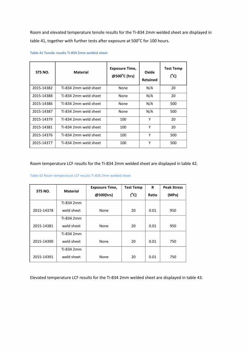
Room and elevated temperature tensile results for the Ti-834 2mm welded sheet are displayed in
table 41, together with further tests after exposure at 500oC for 100 hours.
Table 41 Tensile results Ti-834 2mm welded sheet
STS NO. Material Exposure Time,
@500oC (hrs)
Oxide
Retained
Test Temp
(oC)
2015-14382 Ti-834 2mm weld sheet None N/A 20
2015-14388 Ti-834 2mm weld sheet None N/A 20
2015-14386 Ti-834 2mm weld sheet None N/A 500
2015-14387 Ti-834 2mm weld sheet None N/A 500
2015-14379 Ti-834 2mm weld sheet 100 Y 20
2015-14381 Ti-834 2mm weld sheet 100 Y 20
2015-14376 Ti-834 2mm weld sheet 100 Y 500
2015-14377 Ti-834 2mm weld sheet 100 Y 500
Room temperature LCF results for the Ti-834 2mm welded sheet are displayed in table 42.
Table 42 Room temperature LCF results Ti-834 2mm welded sheet
STS NO. Material Exposure Time,
@500(hrs)
Test Temp
(oC)
R
Ratio
Peak Stress
(MPa)
2015-14378
Ti-834 2mm
weld sheet None 20 0.01 950
2015-14381
Ti-834 2mm
weld sheet None 20 0.01 950
2015-14390
Ti-834 2mm
weld sheet None 20 0.01 750
2015-14391
Ti-834 2mm
weld sheet None 20 0.01 750
Elevated temperature LCF results for the Ti-834 2mm welded sheet are displayed in table 43.
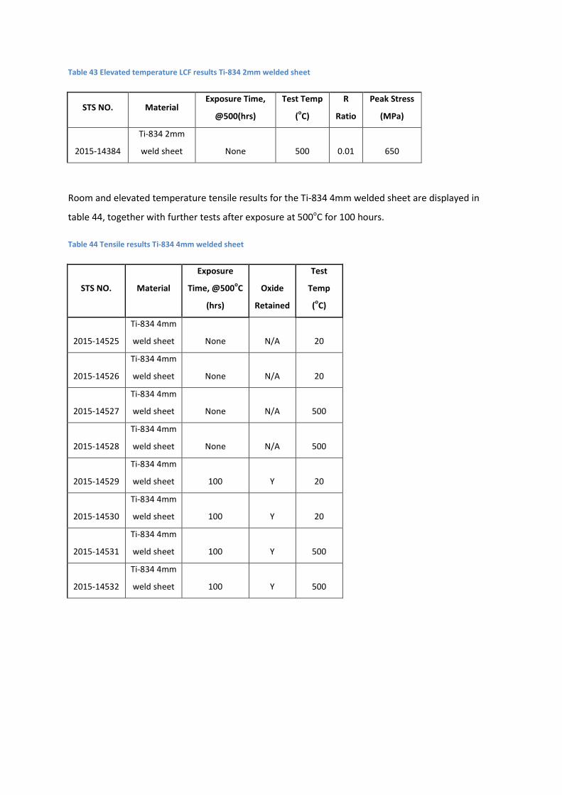
Table 43 Elevated temperature LCF results Ti-834 2mm welded sheet
STS NO. Material Exposure Time,
@500(hrs)
Test Temp
(oC)
R
Ratio
Peak Stress
(MPa)
2015-14384
Ti-834 2mm
weld sheet None 500 0.01 650
Room and elevated temperature tensile results for the Ti-834 4mm welded sheet are displayed in
table 44, together with further tests after exposure at 500oC for 100 hours.
Table 44 Tensile results Ti-834 4mm welded sheet
STS NO. Material
Exposure
Time, @500oC
(hrs)
Oxide
Retained
Test
Temp
(oC)
2015-14525
Ti-834 4mm
weld sheet None N/A 20
2015-14526
Ti-834 4mm
weld sheet None N/A 20
2015-14527
Ti-834 4mm
weld sheet None N/A 500
2015-14528
Ti-834 4mm
weld sheet None N/A 500
2015-14529
Ti-834 4mm
weld sheet 100 Y 20
2015-14530
Ti-834 4mm
weld sheet 100 Y 20
2015-14531
Ti-834 4mm
weld sheet 100 Y 500
2015-14532
Ti-834 4mm
weld sheet 100 Y 500

Room temperature LCF results for the Ti-834 4mm welded sheet are displayed in table 45.
Table 45 Room temperature LCF results Ti-834 4mm welded sheet
STS NO. Material Exposure Time,
@500(hrs)
Test Temp
(oC)
R
Ratio
Peak Stress
(MPa)
2015-14533
Ti-834 4mm
weld sheet None 20 0.01 950
2015-14534
Ti-834 4mm
weld sheet None 20 0.01 750
2015-14535
Ti-834 4mm
weld sheet None 20 0.01 950
2015-14536
Ti-834 4mm
weld sheet None 20 0.01 750
Elevated temperature LCF results for the Ti-834 4mm welded sheet are displayed in table 46.
Table 46 Elevated temperature LCF results Ti-834 4mm welded sheet
STS NO. Material Exposure Time,
@500(hrs)
Test Temp
(oC)
R
Ratio
Peak Stress
(MPa)
2015-14537
Ti-834 4mm
weld sheet None 500 0.01 750
2015-14538
Ti-834 4mm
weld sheet None 500 0.01 650
4. Discussion
4.1 Tensile Results
Initial tensile testing of Ti-6242S centrifugally cast material found that the material had reasonably
high strength and ductility in both 13mm and 25mm sections. This was evident at both room and
elevated temperatures. Exposure at the current operating temperature of Ti-6242S (450oC) for 1000
hours was not found to have a dramatic effect on properties; only slightly reducing the ductility of
the material when it was tested with the resultant oxide layer retained.
After positive results from the initial room and elevated temperature tensile testing of Ti-834
centrifugally cast material, it soon became apparent that there was a considerable loss of ductility in
the alloy after prolonged exposure at the proposed operating temperature of 500oC. This loss of

ductility became the main focus of the project and as a result further tests were performed on the
alloy after different exposure times. It can clearly be seen in figure 19 that a reduction in ductility is
seen in line with increasing exposure times when the resultant oxide layer is retained at the surface.
Figure 19 Room temperature tensile curves for Ti-834 centrifugally cast alloy after various exposure times, oxide
retained
In order to determine if this oxide layer or changes caused to the bulk of the alloy were responsible
for the loss in ductility, it was decided to perform tests on exposed specimens which then had the
oxide layer removed before testing. By removing the oxide layer it is clear to see in figure 20 that a
significant proportion of this lost ductility is recovered. Removing the oxide layer resulted in similar
ductility values for the three different exposure times, but there was still a significant reduction in
ductility when compared to the material in the unexposed condition. These results show that
changes in the bulk of the material after exposure are responsible for the remaining loss in ductility.
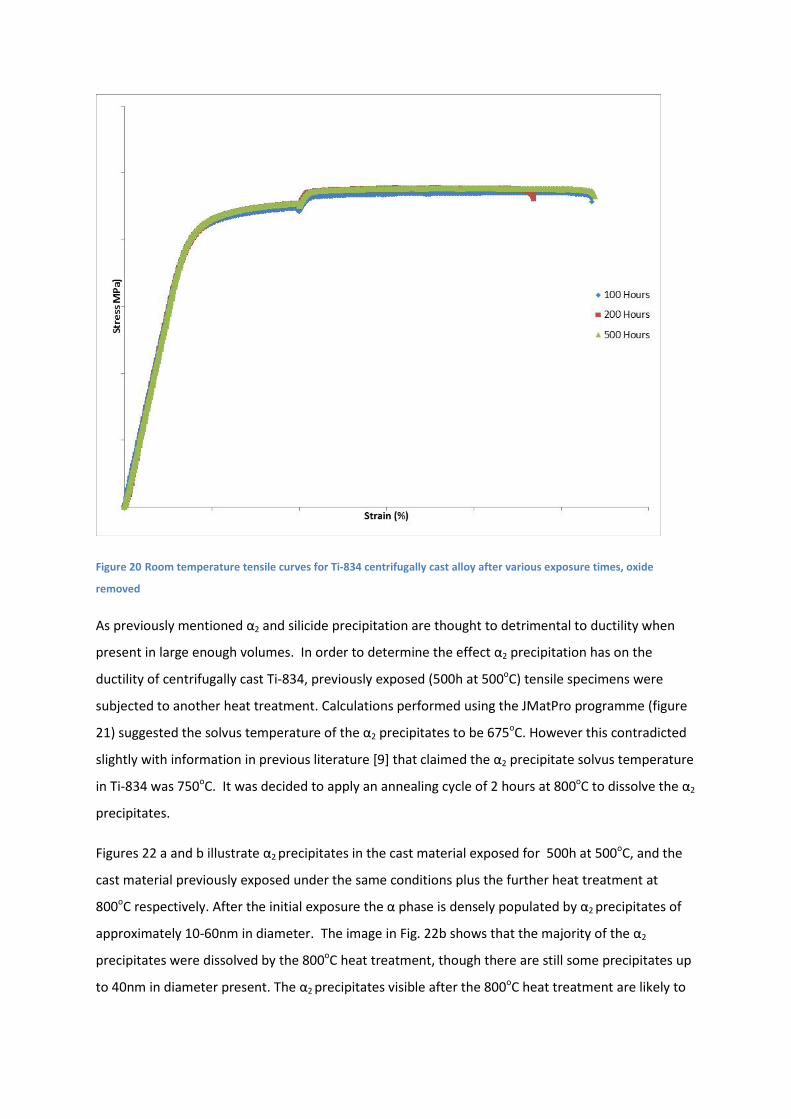
Figure 20 Room temperature tensile curves for Ti-834 centrifugally cast alloy after various exposure times, oxide
removed
As previously mentioned α2 and silicide precipitation are thought to detrimental to ductility when
present in large enough volumes. In order to determine the effect α2 precipitation has on the
ductility of centrifugally cast Ti-834, previously exposed (500h at 500oC) tensile specimens were
subjected to another heat treatment. Calculations performed using the JMatPro programme (figure
21) suggested the solvus temperature of the α2 precipitates to be 675oC. However this contradicted
slightly with information in previous literature [9] that claimed the α2 precipitate solvus temperature
in Ti-834 was 750oC. It was decided to apply an annealing cycle of 2 hours at 800oC to dissolve the α2
precipitates.
Figures 22 a and b illustrate α2 precipitates in the cast material exposed for 500h at 500oC, and the
cast material previously exposed under the same conditions plus the further heat treatment at
800oC respectively. After the initial exposure the α phase is densely populated by α2 precipitates of
approximately 10-60nm in diameter. The image in Fig. 22b shows that the majority of the α2
precipitates were dissolved by the 800oC heat treatment, though there are still some precipitates up
to 40nm in diameter present. The α2 precipitates visible after the 800oC heat treatment are likely to

have precipitated out on cooling from the annealing temperature. It is reasonable to expect that all
of the pre-existing α2 precipitates were dissolved during this heat cycle where the temperature was
approximately 50oC above the α2 solvus temperature of 750oC.
Figure 21 Calculations performed using JMatPro programme
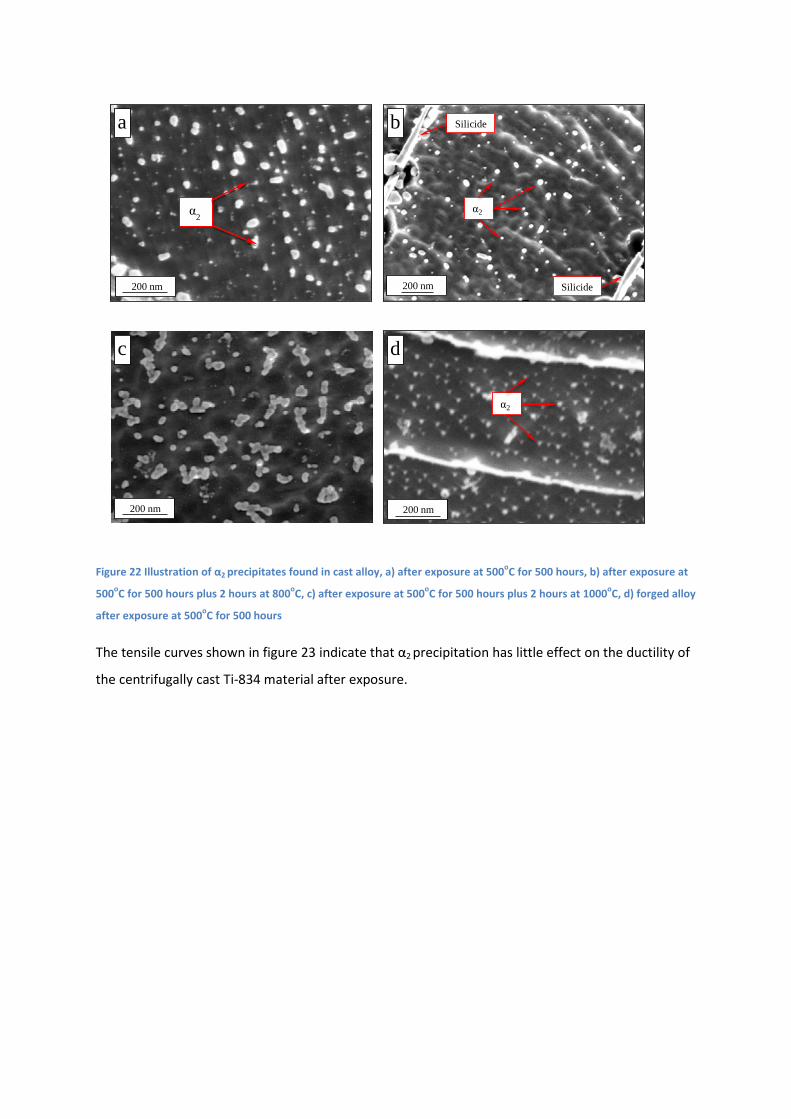
Figure 22 Illustration of α2 precipitates found in cast alloy, a) after exposure at 500oC for 500 hours, b) after exposure at
500oC for 500 hours plus 2 hours at 800oC, c) after exposure at 500oC for 500 hours plus 2 hours at 1000oC, d) forged alloy
after exposure at 500oC for 500 hours
The tensile curves shown in figure 23 indicate that α2 precipitation has little effect on the ductility of
the centrifugally cast Ti-834 material after exposure.
200 nm
Silicide
α2
Silicide
α2
200 nm
200 nm
200 nm
a b
c d
α2
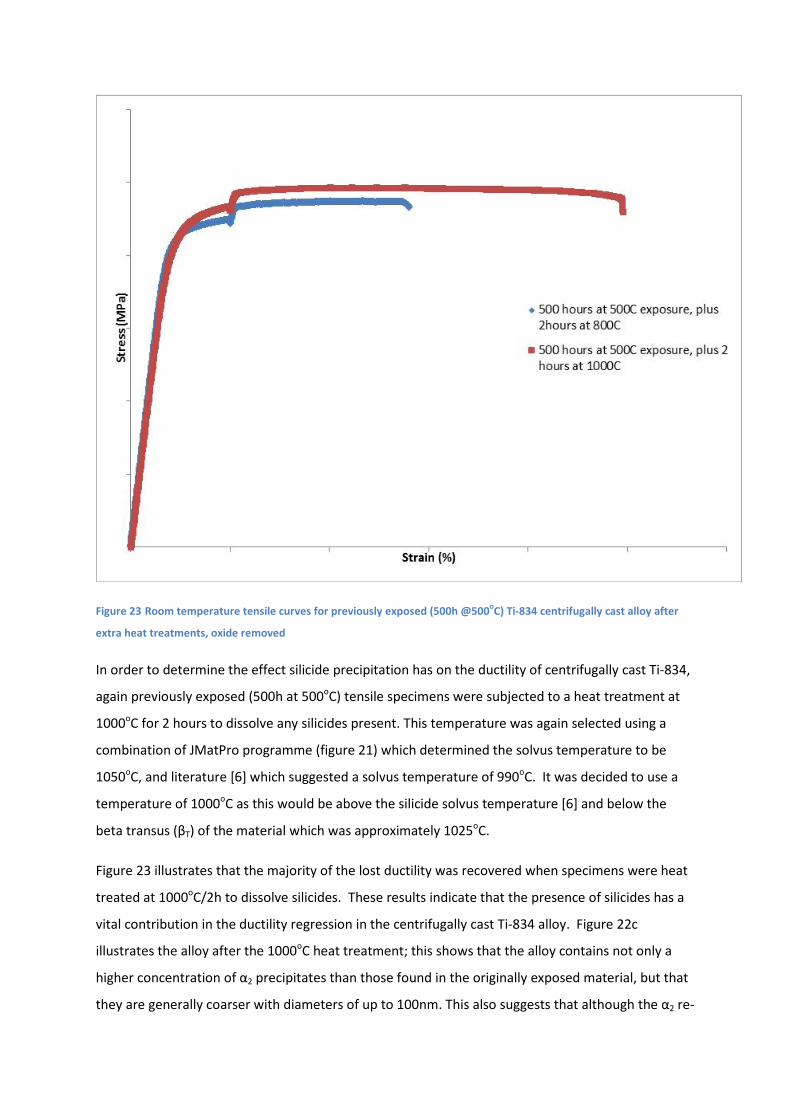
Figure 23 Room temperature tensile curves for previously exposed (500h @500oC) Ti-834 centrifugally cast alloy after
extra heat treatments, oxide removed
In order to determine the effect silicide precipitation has on the ductility of centrifugally cast Ti-834,
again previously exposed (500h at 500oC) tensile specimens were subjected to a heat treatment at
1000oC for 2 hours to dissolve any silicides present. This temperature was again selected using a
combination of JMatPro programme (figure 21) which determined the solvus temperature to be
1050oC, and literature [6] which suggested a solvus temperature of 990oC. It was decided to use a
temperature of 1000oC as this would be above the silicide solvus temperature [6] and below the
beta transus (βT) of the material which was approximately 1025oC.
Figure 23 illustrates that the majority of the lost ductility was recovered when specimens were heat
treated at 1000oC/2h to dissolve silicides. These results indicate that the presence of silicides has a
vital contribution in the ductility regression in the centrifugally cast Ti-834 alloy. Figure 22c
illustrates the alloy after the 1000oC heat treatment; this shows that the alloy contains not only a
higher concentration of α2 precipitates than those found in the originally exposed material, but that
they are generally coarser with diameters of up to 100nm. This also suggests that although the α2 re-

precipitated during cooling and formed more and larger α2 precipitates they did not affect the
tensile ductility of the material.
Figure 24a and 20d show high-resolution backscatter SEM images for centrifugally cast Ti-834 prior
and after 500oC/500h exposure, respectively. The 2D EDX silicon and zirconium maps for Figure 24a
are shown in and 24b and 24c and for Figure 24d in 24e and 24f, respectively. As shown in Figure
24a, small silicides (~ 400-900 nm in diameter) with irregular shape are located on the α/β phase
boundaries throughout the cast material prior to any exposure. Figure 24d-f, show the 500oC/500h
exposure increased the concentration of silicides greatly in the centrifugally cast alloy. The silicides
were also found to be much coarser than those seen in the unexposed material; up to 2.5µm in
diameter. Furthermore, the exposure at 500oC for 500h caused the existing silicides to coarsen on
α/β phase boundaries and a large number of silicides precipitates were observed within the α
lamellae. It is evident from Figure 24g, that the silicide coarsening on α/β phase boundaries caused
large voids formation around the precipitates. This is an indication that the silicide lost its coherency
with the α matrix at this stage.
Figure 24 high-resolution backscatter SEM images for centrifugally cast Ti-834, a) prior to 500oC/500h exposure, b) 2D
EDX silicon map for Figure 24a, c) 2D EDX zirconium map for Figure 24a, d) after 500oC/500h exposure, e) 2D EDX silicon
map for Figure 24d, f) 2D EDX zirconium map for Figure 24d, g) large void formation around the precipitates silicide
caused by coarsening on α/β phase boundaries.
Figure 25 a-c shows the microstructure (a) and EDX chemical analyses (b and c) of centrifugally cast
Ti-834 alloy following 500ºC/500h exposure and heat treatment at 800ºC/2h. It is clear from the
figure that 800oC/2h heat treatment has enabled further silicide precipitation and the coarsening of
existing silicides to occur. As shown in Figure 25d, further voids were formed on silicide/matrix
ba c
10μmSi Zr
1μm10μm
ed gf
Si Zr
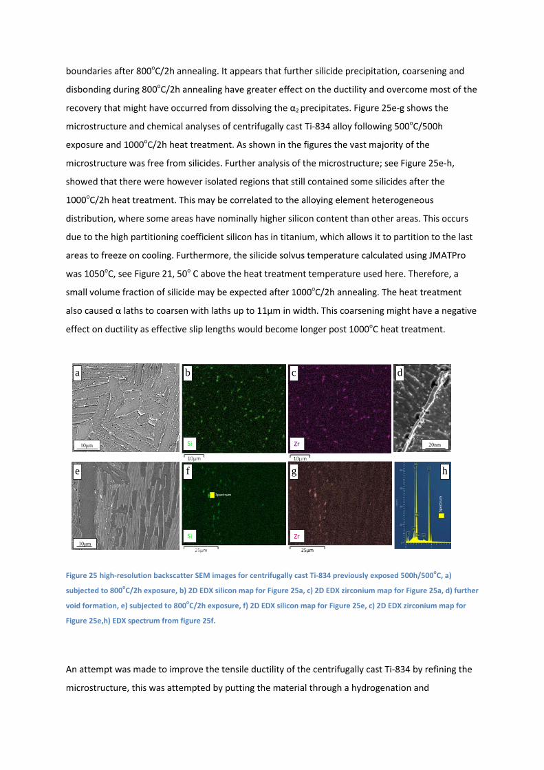
boundaries after 800oC/2h annealing. It appears that further silicide precipitation, coarsening and
disbonding during 800oC/2h annealing have greater effect on the ductility and overcome most of the
recovery that might have occurred from dissolving the α2 precipitates. Figure 25e-g shows the
microstructure and chemical analyses of centrifugally cast Ti-834 alloy following 500oC/500h
exposure and 1000oC/2h heat treatment. As shown in the figures the vast majority of the
microstructure was free from silicides. Further analysis of the microstructure; see Figure 25e-h,
showed that there were however isolated regions that still contained some silicides after the
1000oC/2h heat treatment. This may be correlated to the alloying element heterogeneous
distribution, where some areas have nominally higher silicon content than other areas. This occurs
due to the high partitioning coefficient silicon has in titanium, which allows it to partition to the last
areas to freeze on cooling. Furthermore, the silicide solvus temperature calculated using JMATPro
was 1050oC, see Figure 21, 50o C above the heat treatment temperature used here. Therefore, a
small volume fraction of silicide may be expected after 1000oC/2h annealing. The heat treatment
also caused α laths to coarsen with laths up to 11µm in width. This coarsening might have a negative
effect on ductility as effective slip lengths would become longer post 1000oC heat treatment.
Figure 25 high-resolution backscatter SEM images for centrifugally cast Ti-834 previously exposed 500h/500oC, a)
subjected to 800oC/2h exposure, b) 2D EDX silicon map for Figure 25a, c) 2D EDX zirconium map for Figure 25a, d) further
void formation, e) subjected to 800oC/2h exposure, f) 2D EDX silicon map for Figure 25e, c) 2D EDX zirconium map for
Figure 25e,h) EDX spectrum from figure 25f.
An attempt was made to improve the tensile ductility of the centrifugally cast Ti-834 by refining the
microstructure, this was attempted by putting the material through a hydrogenation and
ZrSi10μm 20nm
ba dc
10μmSi Zr
fe hg
Spectrum
Spec
trum

dehydrogenation (HDH) process. The microstructures of the 13mm and 23mm products shown in in
figures 11and 12 shows that this was achieved with both products displaying finer prior β grains;
especially so with the 13mm material. The internal structure of the grains was also modified by this
process which developed more of a Widmanstatten structure, not the coarse α laths seen in the
standard material. The potential of this process can be seen by 2 tensile results from the 13mm
material where an elongation of 10.3% was seen at 500oC and another where 13% elongation is
recorded at room temperature after a 100 hour exposure. However the possible Improvement in
ductility was undermined by the dehydrogenation process where it proved very difficult to remove
sufficient hydrogen from the material, causing embrittlement of the material leading to the poor
ductility seen for the majority of the tests. Hydrogen analysis performed on the material found
approximately 110ppm hydrogen remaining in the material tested.
The amount of hydrogen retained after the dehydrogenation process also compromised the testing
of specimens after different exposure times. All but three of the specimens that were exposed at
500oC were found to have cracks present on the gauge of the test specimen as seen figure 26.
The results attained for the second batch of hydrogenated material further show the potential of the
process with improved ductility and more consistency in the results when compared to the initial
hydrogenated material.
Figure 26 a) Crack found on gauge of hydrogenated Ti-834 centrifugally cast specimen exposed for 200h/550oC, b) fracture surface of hydrogenated Ti-834 centrifugally cast specimen exposed for 200h/550oC tensile specimen illustrating oxidation where material had cracked during exposure
As shown in Figure 27, the forged material in the unexposed and exposed for 100, 200 and 500 hour
conditions is stronger and more ductile than its centrifugally cast equivalent. This can be seen in
tables 15 and 21 which show that the forged material in the unexposed condition has a significantly
higher tensile strength with both the UTS and 0.2% proof stress values being approximately 10%
higher than those recorded for the centrifugally cast material. Ductility was also far greater in the
a b

forged material where the elongation was ~%60 greater than achieved by the cast material. Unlike
the Ti-834 centrifugally cast material no loss of ductility was recorded in line with increasing
exposure times for the forged alloy.
As illustrated in figure 23d the forged material which retained its ductility after 500oC/500h exposure
was found to have a high concentration of α2 precipitates, however these were much finer than
those found in the centrifugally cast Ti-834 alloy; with typical diameters of 10-20nm. It appeared
that the homogenous distribution of the very fine α2 precipitates and their high coherency with the α
phase matrix may have assisted in alloy strengthening of the Ti-834 forged alloy with good ductility,
especially at high temperatures. The silicides found in the forged material had a similar irregular
shape to those found in the centrifugally cast alloy; however as with the α2 precipitates they were
much smaller in size; in the range of 80nm – 200nm. The fine silicide size in the wrought alloy is
attributed to the smaller volume fraction of β phase in between α lamellaes in the bimodal
microstructure of the forged material. It appears there is no significant increase in the overall
concentration of silicides present in the bimodal microstructure. This further explains the ductility
preservation of the forged Ti-834 alloy after 500oC/500h exposure. It was also rather apparent that
existing silicides did not coarsened during the exposure; their diameters remained stable at
approximately 100-200 nm.
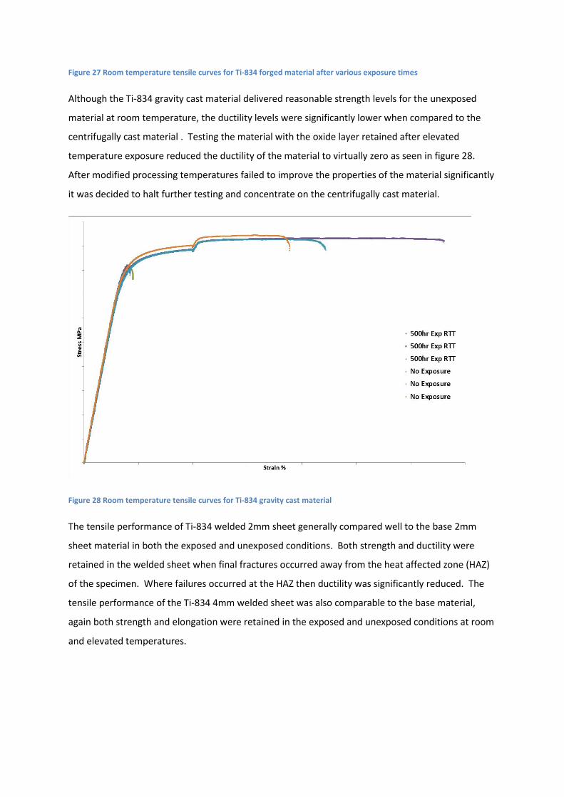
Figure 27 Room temperature tensile curves for Ti-834 forged material after various exposure times
Although the Ti-834 gravity cast material delivered reasonable strength levels for the unexposed
material at room temperature, the ductility levels were significantly lower when compared to the
centrifugally cast material . Testing the material with the oxide layer retained after elevated
temperature exposure reduced the ductility of the material to virtually zero as seen in figure 28.
After modified processing temperatures failed to improve the properties of the material significantly
it was decided to halt further testing and concentrate on the centrifugally cast material.
Figure 28 Room temperature tensile curves for Ti-834 gravity cast material
The tensile performance of Ti-834 welded 2mm sheet generally compared well to the base 2mm
sheet material in both the exposed and unexposed conditions. Both strength and ductility were
retained in the welded sheet when final fractures occurred away from the heat affected zone (HAZ)
of the specimen. Where failures occurred at the HAZ then ductility was significantly reduced. The
tensile performance of the Ti-834 4mm welded sheet was also comparable to the base material,
again both strength and elongation were retained in the exposed and unexposed conditions at room
and elevated temperatures.
a. LCF
All strain levels used during the project were suggested by GKN at the outset. Room temperature
tests, on cast products were to be carried out at 0.55 and 1% peak strain levels. At elevated
temperature, tests on cast products were to be carried out at 0.65 and 1.2% peak strain levels. For
the forged material higher strain levels were applied; at room temperature strain levels of 0.8 and
1.5% were applied, while at room temperature the lower level was increased to 0.9%. It was initially
intended that all LCF tests on sheet products were to be performed under strain control conditions.
However this was not possible due to buckling of the specimens after initial yielding. It was decided
that all sheet and welded sheet would be tested under stress control conditions. At room
temperature stress levels of 750 and 950MPa were applied, while at elevated temperature these
were reduced to 650 and 750MPa.
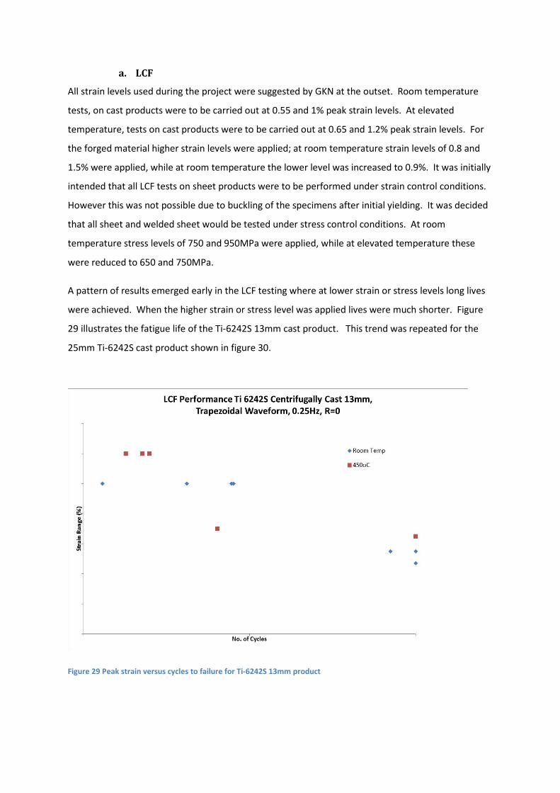
A pattern of results emerged early in the LCF testing where at lower strain or stress levels long lives
were achieved. When the higher strain or stress level was applied lives were much shorter. Figure
29 illustrates the fatigue life of the Ti-6242S 13mm cast product. This trend was repeated for the
25mm Ti-6242S cast product shown in figure 30.
Figure 29 Peak strain versus cycles to failure for Ti-6242S 13mm product
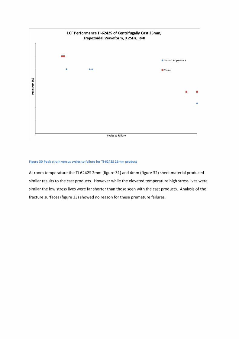
Figure 30 Peak strain versus cycles to failure for Ti-6242S 25mm product
At room temperature the Ti-6242S 2mm (figure 31) and 4mm (figure 32) sheet material produced
similar results to the cast products. However while the elevated temperature high stress lives were
similar the low stress lives were far shorter than those seen with the cast products. Analysis of the
fracture surfaces (figure 33) showed no reason for these premature failures.

Figure 31 Peak stress versus cycles to failure for Ti-6242S 2mm sheet product
Figure 32 Peak stress versus cycles to failure for Ti-6242S 4mm sheet product
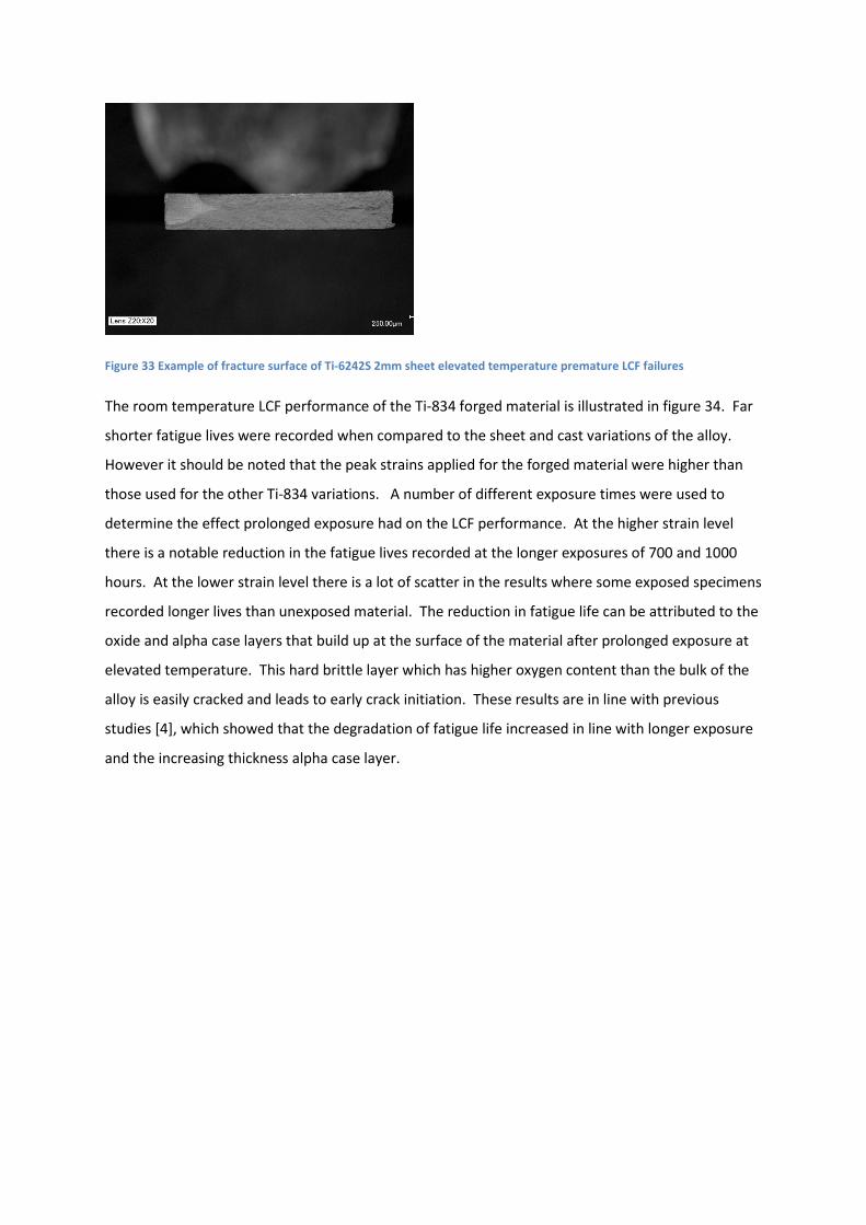
Figure 33 Example of fracture surface of Ti-6242S 2mm sheet elevated temperature premature LCF failures
The room temperature LCF performance of the Ti-834 forged material is illustrated in figure 34. Far
shorter fatigue lives were recorded when compared to the sheet and cast variations of the alloy.
However it should be noted that the peak strains applied for the forged material were higher than
those used for the other Ti-834 variations. A number of different exposure times were used to
determine the effect prolonged exposure had on the LCF performance. At the higher strain level
there is a notable reduction in the fatigue lives recorded at the longer exposures of 700 and 1000
hours. At the lower strain level there is a lot of scatter in the results where some exposed specimens
recorded longer lives than unexposed material. The reduction in fatigue life can be attributed to the
oxide and alpha case layers that build up at the surface of the material after prolonged exposure at
elevated temperature. This hard brittle layer which has higher oxygen content than the bulk of the
alloy is easily cracked and leads to early crack initiation. These results are in line with previous
studies [4], which showed that the degradation of fatigue life increased in line with longer exposure
and the increasing thickness alpha case layer.
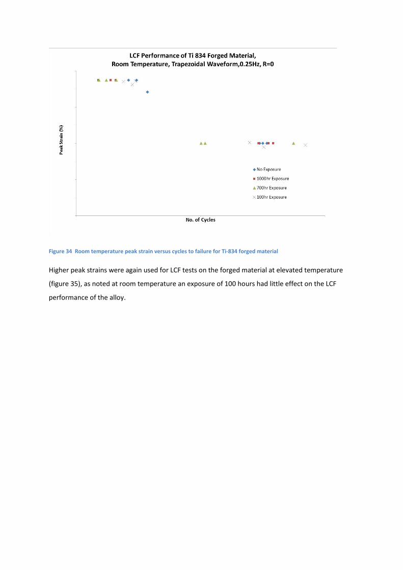
Figure 34 Room temperature peak strain versus cycles to failure for Ti-834 forged material
Higher peak strains were again used for LCF tests on the forged material at elevated temperature
(figure 35), as noted at room temperature an exposure of 100 hours had little effect on the LCF
performance of the alloy.

Figure 35 Elevated temperature peak strain versus cycles to failure for Ti-834 forged material
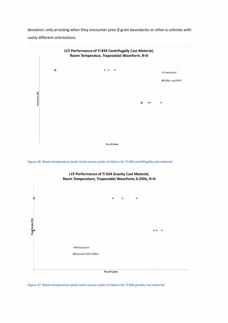
The room temperature LCF results for both the centrifugally cast (figure 36) and gravity cast (figure
37) Ti-834 alloys were disappointing, especially so for the gravity cast material. Short fatigue lives
were recorded at both strain levels in both materials in the unexposed condition. Exposure for 500
hours was found to have a significant effect on the fatigue life, especially on the gravity cast material
which failed on the first cycle under both strain levels. The reduction in fatigue life for the
unexposed material can be attributed to the lamellar microstructure found in the alloys. The
bimodal microstructure found in the forged and sheet materials provides very short effective slip
lengths within the α phase and crack retardation at αp/transformed β boundaries. This contrasts to
the lamellar microstructures of the cast alloys which provide long effective slip lengths. EBSD
analysis of the centrifugally cast alloy shown in figure 38 illustrates that misorientation angles
between α lamellae in this alloy are extremely small; where large numbers of α lamellar within each
colony were found to have very similar orientations, resulting in very low angle grain boundaries
between them. The misorientation angles are shown for L1 (Line 1) and L2 (Line 2) in the same
figure. It is clear that the average misorientation angle between the α lamellaes is 0.60in L1 and 0.90
in L2. This results in far longer effective slip lengths in the cast alloy (~ 450 μm) than those in the
forged alloy (~ 20 μm) using statistical average assumption. Therefore it is not surprising that crack
propagation in the lamellar microstructure of the cast alloys cast is much faster than in the bimodal
microstructures. The lamellar morphology provides an easy crack path through each colony with no
deviation; only arresting when they encounter prior β grain boundaries or other α colonies with
vastly different orientations.
Figure 36 Room temperature peak strain versus cycles to failure for Ti-834 centrifugally cast material
Figure 37 Room temperature peak strain versus cycles to failure for Ti-834 gravity cast material

Figure 38 EBSD orientation map of Ti-834 centrifugally cast material
The LCF performance of both the Ti-834 2mm and 4mm welded sheet shown in figure 39 was
severely compromised by the condition of the weld in all the plates. As illustrated in figure 40c the
microstructure of the HAZ was very coarse when compared to the base sheet material (figure 40b).
As a result cracks initiated very early and propagated quickly through this region leading to complete
failure through the HAZ area of each specimen every test specimen. An example of this is shown in
figure 41.

Figure 39 Room temperature peak stress versus cycles to failure for Ti-834 welded sheet material
Figure 40 Images of Ti-834 2mm welded sheet
a
c b H.A.Z. Base Sheet Material
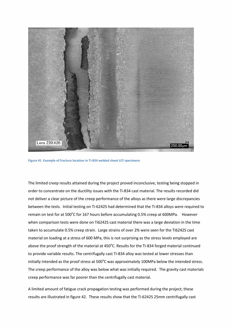
Figure 41 Example of fracture location in Ti-834 welded sheet LCF specimens
The limited creep results attained during the project proved inconclusive, testing being stopped in
order to concentrate on the ductility issues with the Ti-834 cast material. The results recorded did
not deliver a clear picture of the creep performance of the alloys as there were large discrepancies
between the tests. Initial testing on Ti-6242S had determined that the Ti-834 alloys were required to
remain on test for at 500oC for 167 hours before accumulating 0.5% creep at 600MPa. However
when comparison tests were done on Ti6242S cast material there was a large deviation in the time
taken to accumulate 0.5% creep strain. Large strains of over 2% were seen for the Ti6242S cast
material on loading at a stress of 600 MPa, this is not surprising as the stress levels employed are
above the proof strength of the material at 450oC. Results for the Ti-834 forged material continued
to provide variable results. The centrifugally cast Ti-834 alloy was tested at lower stresses than
initially intended as the proof stress at 500oC was approximately 100MPa below the intended stress.
The creep performance of the alloy was below what was initially required. The gravity cast materials
creep performance was far poorer than the centrifugally cast material.
A limited amount of fatigue crack propagation testing was performed during the project; these
results are illustrated in figure 42. These results show that the Ti-6242S 25mm centrifugally cast

material has the lowest FCP rate of the 5 materials tested. The Ti-6242S 13mm, Ti-834 centrifugally
and gravity cast materials all have similar intermediate FCP rates. Unsurprisingly the Ti-834 forged
material with the bimodal microstructure displays the fastest FCP rate of all the materials. The curve
for this material is much smoother that those displayed by the cast materials whose curves are
characterized by a rougher profile. This can be explained by cracks advancing quickly through the
aligned lamellar structures relatively unhindered until they encounter grain boundaries; where their
growth is retarded before accelerating once again through the large prior B grains. This is illustrated
in figures 43 a & b where the forged material has a smooth crack profile compared to the rough
jagged profile of the cast material.
Figure 42 Room temperature FCP result for all materials

Figure 43 Crack path of a) Ti-834 forged material, b) Ti-834 centrifugally cast material
a b
5. Summary Initial monotonic testing of the Ti-834 cast material provided positive results, the material
demonstrated good ductility and strength at both room and elevated temperatures, and appeared
capable of replacing Ti-6242S as an intermediate compressor casing material. Although its LCF
performance caused some concern; the effect of long term exposure at the intended operating
temperature on ductility is the major obstacle in its way. While the cast form of Ti-6242S maintains
approximately 10% ductility at room temperature after 1000 hours exposure at its operating
temperature, centrifugally cast Ti-834 only provides approximately 2% ductility after 500 hours
exposure at 500oC
The hydrogenation process performed to improve mechanical properties by modifying the grain size
of the Ti-834 centrifugally cast material was successful in as far as the structure produced by the
process. However the fact that some samples were cracked after the HDH process, and excessive
hydrogen was still present after the de gassing stage of the process compromised its mechanical
performance. Two tensile tests illustrated that it was possible to modify the structure and attain
good mechanical properties in the material via this process. However its practicality as an industrial
process must be questioned as it proved unable to reproduce a suitably crack and hydrogen free end
product.
The forged variation of the Ti-834 material performed well both in the unexposed and exposed
conditions retaining good strength and excellent ductility during tensile tests at both room and
elevated temperature. The LCF performance appeared not to be as strong as the Ti-6242S alloy but
this was at higher strain levels than those applied to the Ti-6242S material.
Both the 2mm and 4mm sheet variants of the Ti-834 alloy performed well, they both proved to be
stronger with similar ductility to the Ti-624S sheet alloys at room temperature while having slightly
lower strength at elevated temperature. Prolonged exposure was not found to affect the ductility of
either sheet material significantly. The LCF performance was also found to be comparable to the Ti-
6242S alloy at both room and elevated temperatures.
The tensile performance of the welded Ti-834 sheets was generally good when fracture occurred
away from the HAZ, when fracture occurred in this region ductility was compromised. However due
to the poor quality of the microstructure in the HAZ, the LCF performance was significantly below
the performance required.
The gravity cast variation of the material was not a viable option as a replacement for Ti-6242S with
very poor tensile and LCF performance especially after prolonged exposure at 500oC. This may have

been somewhat expected after studying the microstructure of the material with very large grain size
with coarse α laths.
References
[1] C.E. Shamblen, “Embrittlement of Ti Alloys by Long Time, High Temperature Exposure.pdf,”
Metall. Trans., vol. 2, pp. 277–280, 1971.
[2] R. Gaddam, B. Sefer, R. Pederson, and M.-L. Antti, “Study of alpha-case depth in Ti-6Al-2Sn-
4Zr-2Mo and Ti-6Al-4V,” IOP Conf. Ser. Mater. Sci. Eng., vol. 48, 2013.
[3] Z. Abdallah, K. Perkins, and S. Williams, “Alpha-case kinetics and surface crack growth in the
high-temperature alloy Timetal 834 under creep conditions,” Metall. Mater. Trans. A Phys.
Metall. Mater. Sci., vol. 43, no. 12, pp. 4647–4654, 2012.
[4] R. Gaddam, M. L. Antti, and R. Pederson, “Influence of alpha-case layer on the low cycle
fatigue properties of Ti-6Al-2Sn-4Zr-2Mo alloy,” Mater. Sci. Eng. A, vol. 599, pp. 51–56, 2014.
[5] A. L. Pilchak, W. J. Porter, and R. John, “Room temperature fracture processes of a near-??
titanium alloy following elevated temperature exposure,” J. Mater. Sci., vol. 47, no. 20, pp.
7235–7253, 2012.
[6] W. T. Donlan, J. E. Allison, and J. V. Lasecki, “The Influence of Thermal Exposure on Properties
and Microstructure of Elevated Temperature Titanium alloys,” in Titanium 92, 1992, pp. 295–
302.
[7] M. A. Daeubler, D. Helm, and G. Lutjering, “Influence of Heat Treatment on Microstructure
and Mechanical Properties of Cast IMI 834,” in Titanium 95, 1995, pp. 709–716.
[8] C.Andres, A.Gysler, and G.Lutjering, “Correlation Between Microstructure and Creep Behavior
of the High Temperature Ti Alloy IMI 834.”
[9] G. Lütjering, “Influence of processing on microstructure and mechanical properties of (α+β)
titanium alloys,” Mater. Sci. Eng. A, vol. 243, no. 1–2, pp. 32–45, 1998.
Appendix a)
BS EN 6892-1:2009 Metallic materials – Tensile testing Part 1: Method of Test at ambient temperature
BS EN ISO 6892-2:2011 Metallic materials. Tensile testing. Method of test at elevated
temperature
BS EN 2002-1:2005 Aerospace series. Metallic materials. Test methods. Tensile
testing at ambient temperature
BS EN 2002-2:2005 Aerospace series. Metallic materials. Test methods. Tensile
testing at elevated temperature
b)
BS 3518-1:1993 Methods of Fatigue Testing
BS 6072:2010 Aerospace series – Metallic materials –Test methods – Constant amplitude fatigue testing
ISO12106:2003 Metallic materials - Fatigue testing. Strain control axial fatigue method.
prEN 3874:1996 Draft European Aerospace Standard - Test methods for metallic materials - Constant amplitude force-controlled low cycle fatigue testing
c)
BS EN ISO 7500-1: 2004 The standard related to the verification of the materials testing machines in tension and compression for increasing forces only. The force verification equipment is calibrated to ISO 376:2002.
BS EN ISO 9513:2012 Methods for the calibration and grading of extensometers for the testing of metals.
BS1041: Part 4 Temperature measurement. Guide to the selection and use of thermocouples.
BS EN 60584-1:1996, IEC 60584-1:1995 Thermocouples. Reference tables.
BS 7270: 2006 Metallic materials. Constant amplitude strain controlled axial fatigue.
ISO12106: 2003 Metallic materials - Fatigue testing. Strain control axial fatigue method.
d)
BS EN ISO 7500-2:2006 Tension creep testing machines – verification of applied load.
BS EN ISO 204:2009 Metallic materials – Uniaxial creep testing in tension
BS EN 2002-005:2007 Aerospace series – Test methods for metallic materials. Part 005: Uninterrupted creep and stress-rupture testing.
BS EN ISO 9513:2012 Metallic materials – Calibration of extensometer systems used in uniaxial testing
e)
BS ISO 12108:2012, Metallic materials – fatigue testing – fatigue crack growth method