Grand Rapids Public Utilities Commission’s hydro turbine ...1569E8A2-964F-47B3... · Utilities...
76
Grand Rapids Public Utilities Commission’s hydro turbine generator December 7 2012 Jeremy Goodell, Jeffrey Lange, Tom Newville, Forrest Semmler Final Technical Report Iron Range Engineering Fall 2012
Transcript of Grand Rapids Public Utilities Commission’s hydro turbine ...1569E8A2-964F-47B3... · Utilities...
Grand Rapids Public
Utilities Commission’s
hydro turbine generator
December 7
2012 Jeremy Goodell, Jeffrey Lange, Tom Newville, Forrest Semmler
Final Technical Report
Iron Range
Engineering Fall 2012
a
Contents Executive Summary ........................................................................................................................ 1
Scoping ........................................................................................................................................... 2
Company Background ................................................................................................................. 2
Company Contacts ...................................................................................................................... 2
Project Description ...................................................................................................................... 2
Expectations ................................................................................................................................ 2
Project Approaches ..................................................................................................................... 3
Engineering Standards................................................................................................................. 4
Economic Analysis ...................................................................................................................... 4
Environmental Concerns ............................................................................................................. 4
Regulations .................................................................................................................................. 4
Project Deliverables .................................................................................................................... 4
Budget ......................................................................................................................................... 5
Project Timeline .......................................................................................................................... 5
Other considerations .................................................................................................................... 5
Confidential Information/ Intellectual Property .......................................................................... 5
Background ..................................................................................................................................... 6
Hydroelectric Power Plant Operations ........................................................................................ 6
Available Power .......................................................................................................................... 6
Hydro Turbine Generator Systems .............................................................................................. 7
Hydro-Turbine Generators .......................................................................................................... 8
Hydro-Turbine Runners .......................................................................................................... 8
Specific Types of Turbines ..................................................................................................... 8
Maintenance .......................................................................................................................... 10
Wastewater Treatment Plant Effluent Pipe ............................................................................... 10
Reusing the existing pipe ...................................................................................................... 11
Relining the pipe ................................................................................................................... 11
Slipping the Existing Pipe ..................................................................................................... 11
Installing a New Pipe ............................................................................................................ 11
b
Water and sewer pipes – cast iron and polymeric type pipes ............................................... 12
Valves & Governing System ..................................................................................................... 12
Turbine Governor.................................................................................................................. 12
Wicket Gate .......................................................................................................................... 13
Needle Valve ......................................................................................................................... 13
Inlet Valve ............................................................................................................................. 14
Building Materials ..................................................................................................................... 14
Under Ground ....................................................................................................................... 14
Above Ground ....................................................................................................................... 15
Connecting the Generation Site to the Electrical Grid Network ............................................... 16
Electrical Switchgear................................................................................................................. 17
Circuit Breakers .................................................................................................................... 17
Protective Relays .................................................................................................................. 18
Transformers ............................................................................................................................. 18
Fire and Electrical Codes .......................................................................................................... 19
Environmental impact statements ............................................................................................. 19
An EIS typically has four sections: ....................................................................................... 19
Environmental Regulations ....................................................................................................... 19
Wastewater Regulations ............................................................................................................ 20
Zoning and Building Codes....................................................................................................... 21
Selling Electrical Power ............................................................................................................ 21
Financing ................................................................................................................................... 22
Grants .................................................................................................................................... 22
Loans ..................................................................................................................................... 23
Available resources ............................................................................................................... 23
Options .......................................................................................................................................... 23
Summary ................................................................................................................................... 23
Turbines ..................................................................................................................................... 23
Pipe Construction ...................................................................................................................... 24
Rerouting the existing pipe ....................................................................................................... 25
Building ..................................................................................................................................... 26

c
Grid Connections....................................................................................................................... 27
Operations ................................................................................................................................. 28
Flow regulation ..................................................................................................................... 28
Operation organization: ............................................................................................................. 29
Financing ................................................................................................................................... 30
Experiment .................................................................................................................................... 32
Summary ................................................................................................................................... 32
Introduction ............................................................................................................................... 32
Apparatus .................................................................................................................................. 33
Mathematical Model ................................................................................................................. 35
Procedure ................................................................................................................................... 35
Results ....................................................................................................................................... 35
Statistical Analysis .................................................................................................................... 36
Conclusion ................................................................................................................................. 37
Recommendations ..................................................................................................................... 37
Economic Analysis ....................................................................................................................... 38
Introduction ............................................................................................................................... 38
Client inputs .............................................................................................................................. 38
Calculations ............................................................................................................................... 38
Costs .......................................................................................................................................... 38
Revenues ................................................................................................................................... 38
Economic analysis results ......................................................................................................... 38
Conclusion ................................................................................................................................. 39
References ................................................................................................................................. 39
Physical Model.............................................................................................................................. 39
Math model ................................................................................................................................... 41
Assumptions .............................................................................................................................. 41
Description of how the math model was developed and executed ........................................... 41
Equations and Calculations ................................................................................................... 41
Evaluation Process .................................................................................................................... 44
Future Steps ............................................................................................................................... 44
d
Validation and verification ........................................................................................................... 44
Team Validation and Verification – Physical Apparatus .......................................................... 44
Team Validation and Verification – Economic Analysis.......................................................... 45
Professional Validation and Verification – Physical Apparatus ............................................... 45
Professional Validation and Verification – Economic Analysis ............................................... 45
Reliability ...................................................................................................................................... 45
Powerhouse Equipment Package .............................................................................................. 45
Polyethylene Pipe ...................................................................................................................... 46
Sustainability analysis ................................................................................................................... 47
Contextualization .......................................................................................................................... 48
Multi-disciplinary aspects of the project ................................................................................... 48
Mechanical engineers/Structural engineers .......................................................................... 48
Electrical engineers ............................................................................................................... 48
Environmental engineers ...................................................................................................... 48
Administration ...................................................................................................................... 49
Project Manager .................................................................................................................... 49
Contractors/builders .............................................................................................................. 49
Hydro dam operators............................................................................................................. 49
Wastewater treatment plant operators ................................................................................... 49
Contextual aspects of the project .............................................................................................. 49
Health .................................................................................................................................... 49
Safety .................................................................................................................................... 49
Environment .......................................................................................................................... 50
Global .................................................................................................................................... 50
Society................................................................................................................................... 50
Ethical, Moral, and Legal...................................................................................................... 50
Economic and Manufacturing ................................................................................................... 50
Engineering, Creativity, & Ingenuity ........................................................................................ 50
Future work ................................................................................................................................... 51
Conclusion .................................................................................................................................... 51
Bibliography ................................................................................................................................. 52

e
Appendix A ...................................................................................................................................... i
List of acronyms used .................................................................................................................. i
Appendix B ..................................................................................................................................... ii
Creation of the turbine used in the experiment ........................................................................... ii
Appendix C .................................................................................................................................... ix
Pictures of the economic analysis .............................................................................................. ix
Appendix D .................................................................................................................................. xiii
Pictures of the GRPUC site ...................................................................................................... xiii
1
Executive Summary The Grand Rapids Public Utilities Commission (GRPUC) asked a team of students from
Iron Range Engineering (IRE) to do a feasibility study on the possibility of placing a
hydroelectric turbine at the outlet of their wastewater treatment plant. The team scoped out the
project by determining the clients expectations, decided what could be accomplished for the
project, and researched any governmental regulations applicable to the project. Research was
done to fully understand all aspects of the project.
Options were created for the effluent pipe, project financing, hydro turbines, turbine
generator building, electrical components, and operations. These options were compared to each
other with weighted charts and using the Pugh method. An experiment was conducted to prove
the theory that different pipe sizes would produce different headlosses which would directly
affect the power output of the system. The team looked into engineering standards and
regulations required to be followed to complete the project.
The team created a computer simulation in Excel from their math model to determine the
power output of the system. This simulation was used for the economic feasibility of the project
by determining the total power output of the turbine generator. The total revenue produced by the
generator was less than the desired 5% internal rate of return (IRR) specified by the client, but it
would produce about 2% IRR for them. A physical model was created to verify the results found
in the original options, and it was found that slipping the pipe might be more difficult than was
originally planned. The team also looked at the reliability and contextual issues related to this
project, and found that the system would be very reliable with few problems.
It is the team’s recommendation to move forward with creating a hydro turbine
generation facility located at the base of the wastewater treatment plant effluent pipe. The
original concrete pipe should be slipped with a 30 inch polyethylene pipe up to the 45 degree
elbows located near the treatment plant. The pipe should then be continued to the plant with a
new trenched route directly to the effluent pipe valve house to reduce costs and increase the
lifespan of the system.
Financing will be decided by the client, but it is recommended that a combination of
loans, grants, and budgeted funds be used to fund the project. Conservation project budgeted
funds and grants should be used as much as possible which will reduce the client’s initial
financial burden. It is recommended that the system be set up for 70kW and be run for 12 hours
a day during the peak energy cost times and connected to the local GRPUC electrical grid so that
the most value can be gained from the stored energy of the water. Finally it is recommended that
a concrete block building be constructed to house the power plant near the Mississippi River due
to its aesthetics and long lifespan.
2
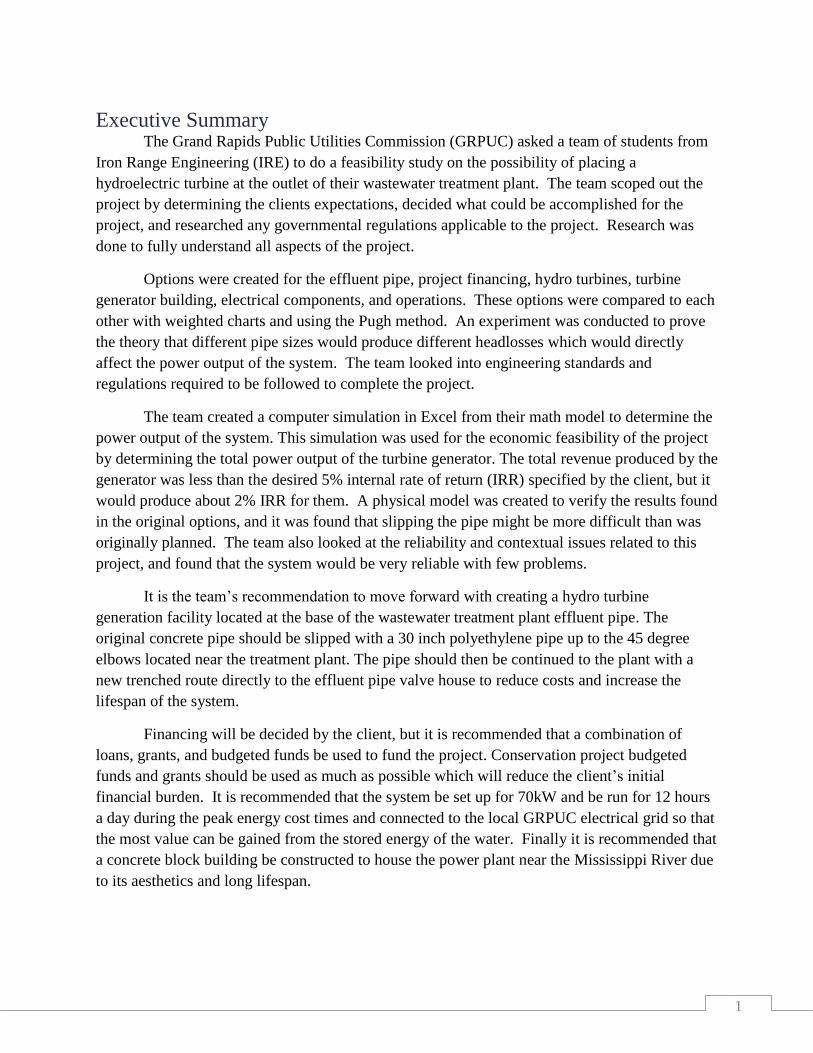
Figure 1 This is a picture of the holding ponds
where the water is stored before being
discharged into the river.
Scoping
Company Background GRPUC is responsible for the distribution of electricity, the treatment and distribution of
water, and the collection and treatment of wastewater for the city of Grand Rapids.
Company Contacts The group’s project contacts were, Glen Hodgson (GRPUC board member), Jim
Ackerman (wastewater treatment plant manager), and Anthony Ward (GRPUC general
manager).
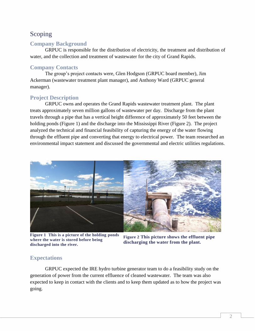
Project Description GRPUC owns and operates the Grand Rapids wastewater treatment plant. The plant
treats approximately seven million gallons of wastewater per day. Discharge from the plant
travels through a pipe that has a vertical height difference of approximately 50 feet between the
holding ponds (Figure 1) and the discharge into the Mississippi River (Figure 2). The project
analyzed the technical and financial feasibility of capturing the energy of the water flowing
through the effluent pipe and converting that energy to electrical power. The team researched an
environmental impact statement and discussed the governmental and electric utilities regulations.
Expectations
GRPUC expected the IRE hydro turbine generator team to do a feasibility study on the
generation of power from the current effluence of cleaned wastewater. The team was also
expected to keep in contact with the clients and to keep them updated as to how the project was
going.
Figure 2 This picture shows the effluent pipe
discharging the water from the plant.
3
Project Approaches The main concerns for the hydroelectric generator to be used for this project can be
broken up into four main areas. The feasibility of using the existing effluent pipe will be
explored. Research will be done to find the best turbine and generator for the project. Electrical
equipment such as switchgear and transformers will be investigated. Finally, the electrical utility
company that the power will be connected to will be chosen.
The current effluent pipe is a 36 inch sewer pipe that carries the discharge of the
wastewater treatment plant to the river. This pipe is at atmospheric pressure, and will need to
hold the pressure of the water head if it is to be used for the project. A study will be completed to
understand if the existing pipe will be able to hold the pressure of the water, or if it would need
upgrades or replacement. A small section of pipe will have to be added to house the turbine.
A hydraulic turbine will remove the energy from the water traveling through the effluent
pipe from the holding ponds to the Mississippi River. There are several different types of water
turbines to be considered for this project including whether to use a single turbine or multiple
turbines in the system. Considerations for what type of turbine to be used include:
The pressure head of the water
The flow rate of the water
The location of the turbine
Total size of the system
Since water turbines generally rotate at slower speeds than gas type turbines, the
generator design will be determined by the turbine selection.
A generator converts the mechanical energy of the turbine into electrical energy. The
amount of energy that can be removed from the water will determine what size of generator will
be used for the project. The amount of energy available may fluctuate; this is due to operational
flexibility and seasonal water requirements. Generator voltage output levels will be researched.
As operating voltages are generally lower than the electrical grid they are connected to, a
transformer will be required to raise the voltage to grid level.
Switchgear and transformers are pieces of electrical equipment that will be used to
transfer the electrical power from the generator to the electrical grid. Switchgears are protective
devices similar to circuit breakers that will be used to isolate the generation site from the grid in
case of an electrical fault or down time. A large power transformer will be used to raise the
system voltage from the generator to the specific electrical grid voltage. This voltage is specified
by the electrical utility company that owns the cables to which the generated power will be
connected.
4
There are three main electrical utility companies within close vicinity of the site to which
the generator could be connected:
Minnesota Power (MP)
Lake Country Power
GRPUC
Engineering Standards The engineering standards this project used include building codes, electrical codes, pipe
codes, environmental regulations and zoning requirements. A separate standards document was
completed for the project.
Economic Analysis Part of the team’s research answered if this project is economically feasible for GRPUC.
The team’s plan was to produce an analysis of the project; this included: cost benefit ratio, IRR,
net present value (NPV), and payback period. An electrical generation plan and schedule was
also produced since electricity can generally be sold for a higher price during daytime hours.
Environmental Concerns New construction requires some form of an environmental impact statement. The
project’s impact statement will need to contain special considerations due to its close vicinity to
the Mississippi River. A short summary of an impact statement was included in the background
section. Since the end product may include fluctuations in the effluence of the wastewater
treatment plant, special attention was be paid to the environmental regulations related to this
impact statement.
Regulations Several government and electrical utility regulations had to be followed; the team
researched and mapped out the processes to be followed to complete the project. All processes
were described in detail to avoid possible project stoppage.
Project Deliverables The project deliverables to the client included a document with:
Preliminary design of the hydroelectric equipment and piping, including ideas for the
turbine building and connections to the electrical grid
Analysis of operational flexibility allowing for the generation of electrical power during
peak hours
Engineering economics analysis including potential funding, revenue, and cost-benefit
analysis
Analysis of potential regulatory constraints (environmental and business)
Recommendations for the potential project implementation
5
Budget IRE supplied the funds needed for the feasibility study, including transportation back and
forth to Grand Rapids for client meetings, the project experiment, general office equipment, and
supplies.
A budget for the client was proposed in the economic analysis section.
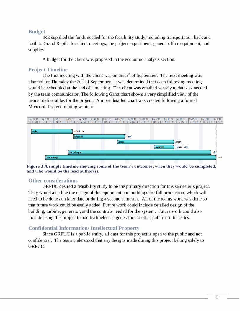
Project Timeline The first meeting with the client was on the 5
th of September. The next meeting was
planned for Thursday the 20th
of September. It was determined that each following meeting
would be scheduled at the end of a meeting. The client was emailed weekly updates as needed
by the team communicator. The following Gantt chart shows a very simplified view of the
teams’ deliverables for the project. A more detailed chart was created following a formal
Microsoft Project training seminar.
Other considerations GRPUC desired a feasibility study to be the primary direction for this semester’s project.
They would also like the design of the equipment and buildings for full production, which will
need to be done at a later date or during a second semester. All of the teams work was done so
that future work could be easily added. Future work could include detailed design of the
building, turbine, generator, and the controls needed for the system. Future work could also
include using this project to add hydroelectric generators to other public utilities sites.
Confidential Information/ Intellectual Property Since GRPUC is a public entity, all data for this project is open to the public and not
confidential. The team understood that any designs made during this project belong solely to
GRPUC.
Figure 3 A simple timeline showing some of the team’s outcomes, when they would be completed,
and who would be the lead author(s).
6
Background
Hydroelectric Power Plant Operations Hydroelectric power plants are operated using electronic control systems and mechanical
flow controls. There are several hydroelectric dams in Minnesota that are run by MP [1].
Currently MP controls all of their hydroelectric dams remotely from a central control station.
The operations at a small scale plant require very little oversight with minimal help from outside
agencies. The current possibilities are to give full operational control over to MP and pay them
for the service, or to give the operational control over to the current wastewater treatment
operations controller and receive help from MP only if something needs maintenance.
Operational costs could be reduced by using the current operator for the wastewater treatment
plant. The job would not vary much from the standard operations that the plant operator would
take [2], and the new technology introduced could make the operators’ job easier.
Usually the hydroelectric station operator controls the flow valves, allowing more or less
water to flow through the pipes as they watch for problems in the system. The operator also
keeps the system maintained, lubricating the system and doing minor repairs [3].
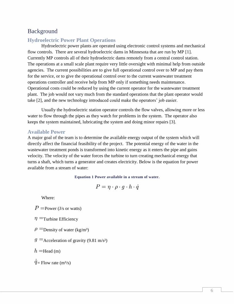
Available Power A major goal of the team is to determine the available energy output of the system which will
directly affect the financial feasibility of the project. The potential energy of the water in the
wastewater treatment ponds is transformed into kinetic energy as it enters the pipe and gains
velocity. The velocity of the water forces the turbine to turn creating mechanical energy that
turns a shaft, which turns a generator and creates electricity. Below is the equation for power
available from a stream of water:
Equation 1 Power available in a stream of water.
Where:
Power (J/s or watts)
Turbine Efficiency
Density of water (kg/m³)
Acceleration of gravity (9.81 m/s²)
Head (m)
= Flow rate (m³/s)
7
For still water, head is the difference in height between the inlet and outlet surfaces.
Moving water has an additional component added to account for the kinetic energy of the flow.
The total head equals the pressure head plus velocity head.
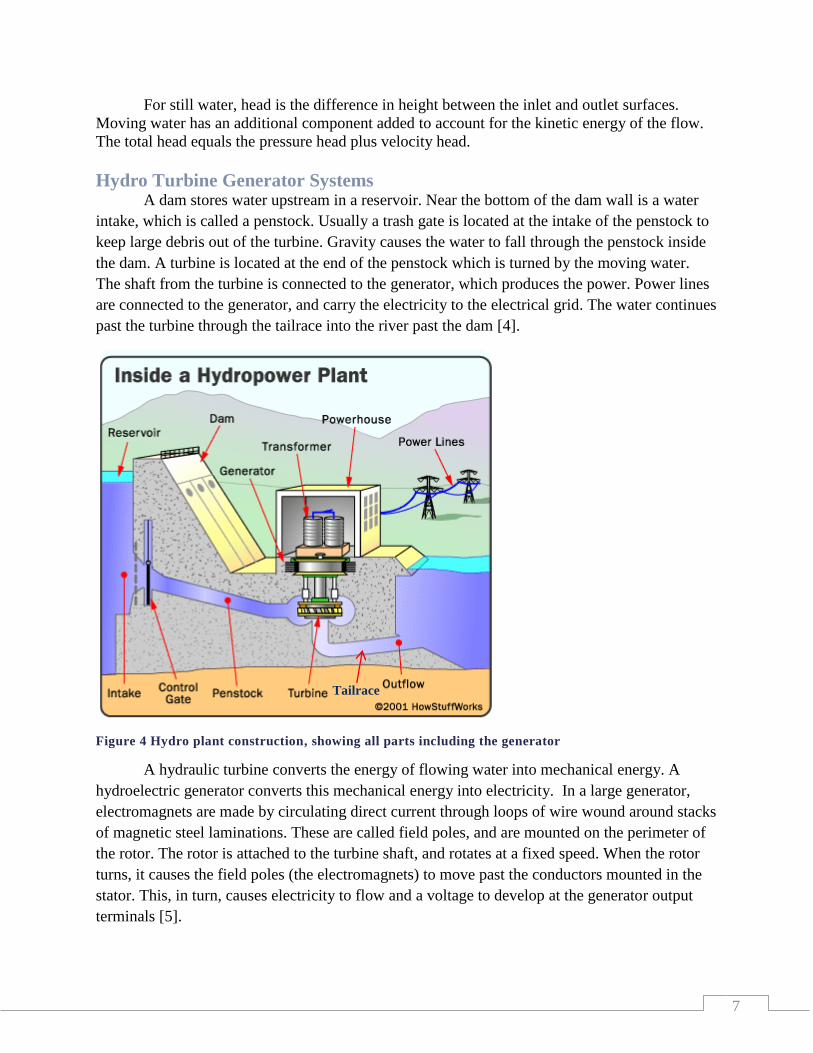
Hydro Turbine Generator Systems A dam stores water upstream in a reservoir. Near the bottom of the dam wall is a water
intake, which is called a penstock. Usually a trash gate is located at the intake of the penstock to
keep large debris out of the turbine. Gravity causes the water to fall through the penstock inside
the dam. A turbine is located at the end of the penstock which is turned by the moving water.
The shaft from the turbine is connected to the generator, which produces the power. Power lines
are connected to the generator, and carry the electricity to the electrical grid. The water continues
past the turbine through the tailrace into the river past the dam [4].
Figure 4 Hydro plant construction, showing all parts including the generator
A hydraulic turbine converts the energy of flowing water into mechanical energy. A
hydroelectric generator converts this mechanical energy into electricity. In a large generator,
electromagnets are made by circulating direct current through loops of wire wound around stacks
of magnetic steel laminations. These are called field poles, and are mounted on the perimeter of
the rotor. The rotor is attached to the turbine shaft, and rotates at a fixed speed. When the rotor
turns, it causes the field poles (the electromagnets) to move past the conductors mounted in the
stator. This, in turn, causes electricity to flow and a voltage to develop at the generator output
terminals [5].
Tailrace
8
Hydro-Turbine Generators
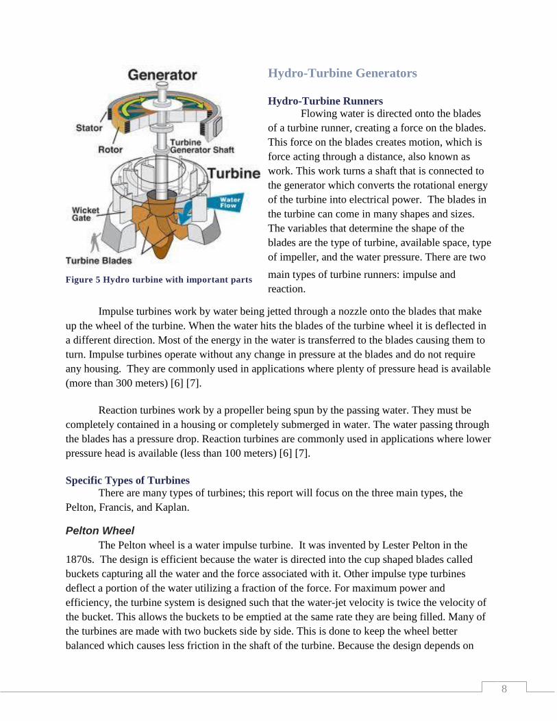
Hydro-Turbine Runners
Flowing water is directed onto the blades
of a turbine runner, creating a force on the blades.
This force on the blades creates motion, which is
force acting through a distance, also known as
work. This work turns a shaft that is connected to
the generator which converts the rotational energy
of the turbine into electrical power. The blades in
the turbine can come in many shapes and sizes.
The variables that determine the shape of the
blades are the type of turbine, available space, type
of impeller, and the water pressure. There are two
main types of turbine runners: impulse and
reaction.
Impulse turbines work by water being jetted through a nozzle onto the blades that make
up the wheel of the turbine. When the water hits the blades of the turbine wheel it is deflected in
a different direction. Most of the energy in the water is transferred to the blades causing them to
turn. Impulse turbines operate without any change in pressure at the blades and do not require
any housing. They are commonly used in applications where plenty of pressure head is available
(more than 300 meters) [6] [7].
Reaction turbines work by a propeller being spun by the passing water. They must be
completely contained in a housing or completely submerged in water. The water passing through
the blades has a pressure drop. Reaction turbines are commonly used in applications where lower
pressure head is available (less than 100 meters) [6] [7].
Specific Types of Turbines
There are many types of turbines; this report will focus on the three main types, the
Pelton, Francis, and Kaplan.
Pelton Wheel
The Pelton wheel is a water impulse turbine. It was invented by Lester Pelton in the
1870s. The design is efficient because the water is directed into the cup shaped blades called
buckets capturing all the water and the force associated with it. Other impulse type turbines
deflect a portion of the water utilizing a fraction of the force. For maximum power and
efficiency, the turbine system is designed such that the water-jet velocity is twice the velocity of
the bucket. This allows the buckets to be emptied at the same rate they are being filled. Many of
the turbines are made with two buckets side by side. This is done to keep the wheel better
balanced which causes less friction in the shaft of the turbine. Because the design depends on
Figure 5 Hydro turbine with important parts
9
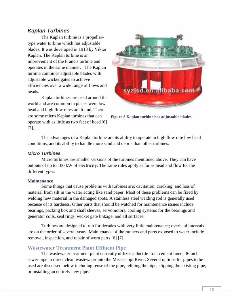
Figure 7 Francis Turbine; guide vanes guide water through
this reaction turbine.
impulse momentum, the turbine works
best in applications with high head (more
than 300 meters). This increases the
velocity coming out of the nozzle
creating more force on the buckets.
The advantages of the Pelton
turbine are its simple design, low cost,
small housing, and its ability to withstand
variations in the flow of the water.
Francis Turbine
Francis turbines are the
most used water turbines today.
The Francis turbine is a reaction
type water turbine that was
developed by James B. Francis. It
is a turbine that combines radial
and axial flow concepts. Being a
reaction type turbine the Francis
operates by a change in pressure.
This means that the turbine must
have a sealed housing to capture
all the energy from the water. The
inlet is spiral shaped; this shape
causes the water to flow into the
guide vanes, which direct the water
tangentially to the turbine wheel,
known as a runner. The radial
flow acts on the runner's vanes, causing the runner to spin. As the water moves through the
runner, its spinning radius decreases, further acting on the runner [6] [7]. The turbines are almost
always mounted with the shaft vertical to keep water away from the generator and also to
facilitate access to it. The guide vanes (or wicket gate) may be adjustable to allow efficient
turbine operation for a range of water flow conditions.
Advantages of a Francis turbine are high efficiency, ability to be designed for a wide
range of heads and flows, and the ability to be used as a pump if reversed.
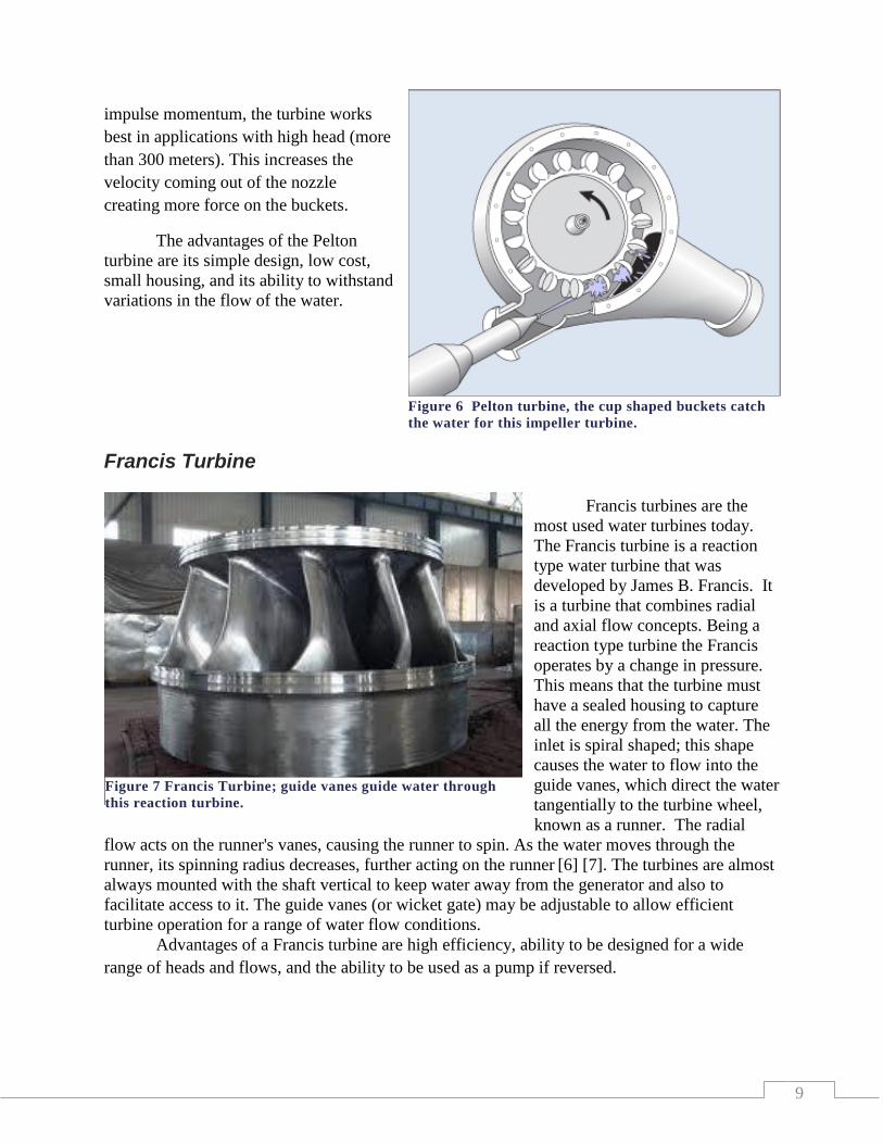
Figure 6 Pelton turbine, the cup shaped buckets catch
the water for this impeller turbine.
10
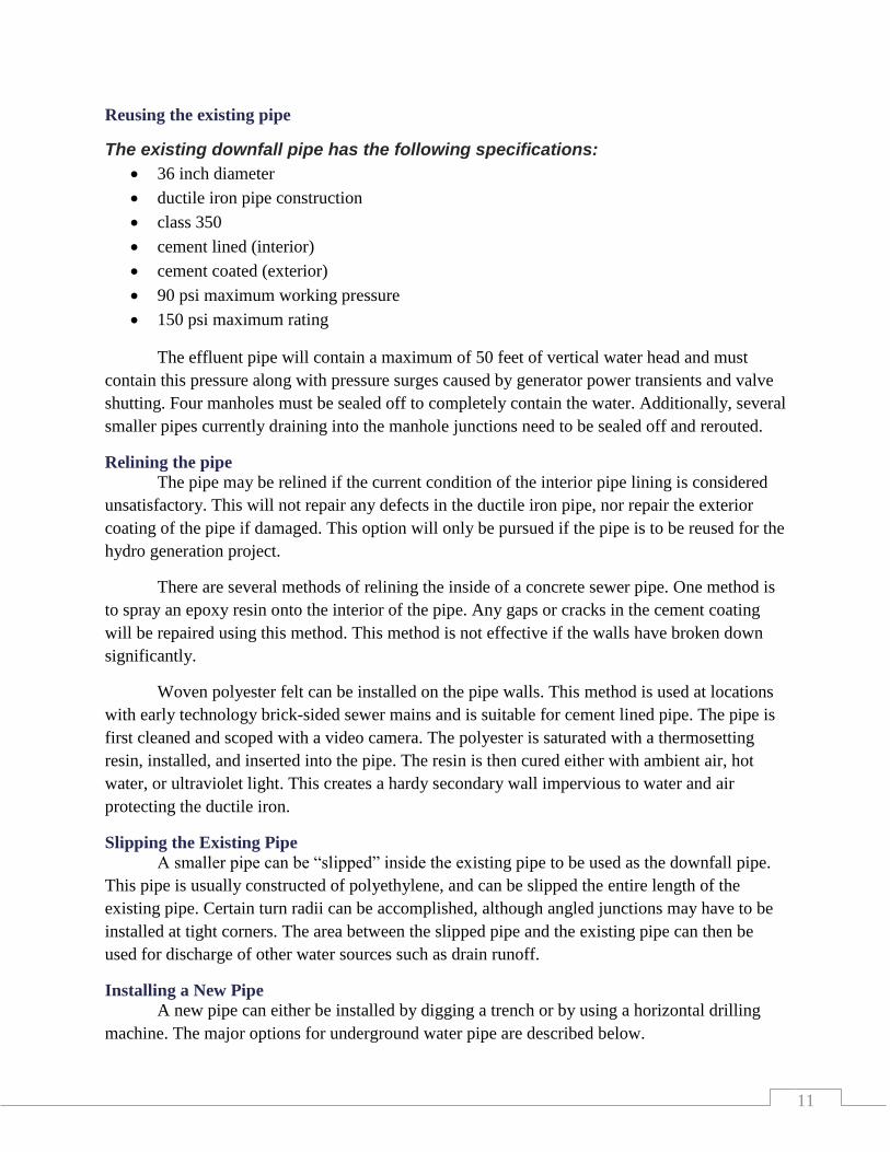
Kaplan Turbines The Kaplan turbine is a propeller-
type water turbine which has adjustable
blades. It was developed in 1913 by Viktor
Kaplan. The Kaplan turbine is an
improvement of the Francis turbine and
operates in the same manner. The Kaplan
turbine combines adjustable blades with
adjustable wicket gates to achieve
efficiencies over a wide range of flows and
heads.
Kaplan turbines are used around the
world and are common in places were low
head and high flow rates are found. There
are some micro Kaplan turbines that can
operate with as little as two feet of head [6]
[7].
The advantages of a Kaplan turbine are its ability to operate in high flow rate low head
conditions, and its ability to handle more sand and debris than other turbines.
Micro Turbines
Micro turbines are smaller versions of the turbines mentioned above. They can have
outputs of up to 100 kW of electricity. The same rules apply as far as head and flow for the
different types.
Maintenance
Some things that cause problems with turbines are: cavitation, cracking, and loss of
material from silt in the water acting like sand paper. Most of these problems can be fixed by
welding new material in the damaged spots. A stainless steel welding rod is generally used
because of its hardness. Other parts that should be watched for maintenance issues include
bearings, packing box and shaft sleeves, servomotors, cooling systems for the bearings and
generator coils, seal rings, wicket gate linkage, and all surfaces.
Turbines are designed to run for decades with very little maintenance; overhaul intervals
are on the order of several years. Maintenance of the runners and parts exposed to water include
removal, inspection, and repair of worn parts [6] [7].
Wastewater Treatment Plant Effluent Pipe The wastewater treatment plant currently utilizes a ductile iron, cement lined, 36 inch
sewer pipe to direct clean wastewater into the Mississippi River. Several options for pipes to be
used are discussed below including reuse of the pipe, relining the pipe, slipping the existing pipe,
or installing an entirely new pipe.
Figure 8 Kaplan turbine has adjustable blades
11
Reusing the existing pipe
The existing downfall pipe has the following specifications:
36 inch diameter
ductile iron pipe construction
class 350
cement lined (interior)
cement coated (exterior)
90 psi maximum working pressure
150 psi maximum rating
The effluent pipe will contain a maximum of 50 feet of vertical water head and must
contain this pressure along with pressure surges caused by generator power transients and valve
shutting. Four manholes must be sealed off to completely contain the water. Additionally, several
smaller pipes currently draining into the manhole junctions need to be sealed off and rerouted.
Relining the pipe
The pipe may be relined if the current condition of the interior pipe lining is considered
unsatisfactory. This will not repair any defects in the ductile iron pipe, nor repair the exterior
coating of the pipe if damaged. This option will only be pursued if the pipe is to be reused for the
hydro generation project.
There are several methods of relining the inside of a concrete sewer pipe. One method is
to spray an epoxy resin onto the interior of the pipe. Any gaps or cracks in the cement coating
will be repaired using this method. This method is not effective if the walls have broken down
significantly.
Woven polyester felt can be installed on the pipe walls. This method is used at locations
with early technology brick-sided sewer mains and is suitable for cement lined pipe. The pipe is
first cleaned and scoped with a video camera. The polyester is saturated with a thermosetting
resin, installed, and inserted into the pipe. The resin is then cured either with ambient air, hot
water, or ultraviolet light. This creates a hardy secondary wall impervious to water and air
protecting the ductile iron.
Slipping the Existing Pipe
A smaller pipe can be “slipped” inside the existing pipe to be used as the downfall pipe.
This pipe is usually constructed of polyethylene, and can be slipped the entire length of the
existing pipe. Certain turn radii can be accomplished, although angled junctions may have to be
installed at tight corners. The area between the slipped pipe and the existing pipe can then be
used for discharge of other water sources such as drain runoff.
Installing a New Pipe
A new pipe can either be installed by digging a trench or by using a horizontal drilling
machine. The major options for underground water pipe are described below.

12
Water and sewer pipes – cast iron and polymeric type pipes
Ductile iron is a form of cast iron whose major property includes nodular graphite
inclusions. These nodules are introduced into the iron by addition of spherical nodulizing
elements, instead of flakes, such as magnesium. This minimizes cracking of the iron creating a
more flexible and elastic structure. Ductile iron is formed in the shape of a pipe and is usually
lined internally and externally with some type of liner.
Ductile iron is only somewhat resistant to corrosion from potable water and sewage, and
is generally not used unprotected within these types of systems. Cement mortar is commonly
used to line the interior of the pipe which reduces corrosion of the iron. Polyurethane coating is
also used for pipes carrying water and inhibits corrosion of the pipe.
A polyethylene sleeve is placed on a large majority of ductile iron pipes. The sleeve
loosely fits over the exterior of the pipe and reduces corrosion by a number of factors. It
physically separates the iron from the soil preventing direct galvanic corrosion. Although it
provides a relatively impermeable layer to ground water, some is allowed to collect between the
sleeve and the pipe. This creates a low oxygen environment, which allows for a small amount of
corrosion to occur evenly over the length of the pipe [8].
Polymeric materials consist of polyvinyl chloride (PVC), high density polyethylene
(HDPE), low density polyethylene (LDPE), and polypropylene. All are a chemical compound or
mixture of compounds consisting of repeating structural units created through a process of
polymerization. These compounds are very light and flexible making them easy to work with.
Polymers are generally corrosion resistant, and resist degradation when protected from
UV rays and heat. Pipes of these compounds can be constructed in various diameters, wall
thicknesses, and lengths. Internal pressure may be limited due to pipe wall strength and fatigue
factors [9].
Valves & Governing System Turbine Governor
The governor uses either mechanical or electronic feedback to sense the speed of the
turbine. Proportional or directional valves controlled by the governor operate cylinders that open
and close wicket gates or needle valves to adjust the flow of water to the turbine in order to
maintain a constant turbine speed. Hydroelectric turbines rotate at relatively low speeds
compared to steam turbines, with larger hydroelectric turbines rotating at 35-75 rpm, and smaller
ones as fast as 150 rpm. The large turbine diameter combined with the massive inertia of the
water flowing through it makes precise control of rotational speed a critical concern [10] [11].
If governor proportional or directional valves do not respond instantly and accurately to
fluctuating generator loads, lagging of the wicket or needle valve position can occur. This results
in an oscillating condition whereby the turbine is constantly speeding up and slowing down. This
inefficient power production, although difficult to quantify, leads to loss in revenue for the
13
utility. Furthermore, if this oscillation exceeds the maximum allowable frequency, then the
turbine must be shut down, resulting in temporary loss of generating production.
As with steam turbines, malfunctioning of the governor could result in a dangerous
runaway (over-speed) condition. Runaway speed is the speed at which the turbine exceeds its
designed maximum rotational speed. When this occurs it is possible for the turbine to
disintegrate due to massive centrifugal forces.
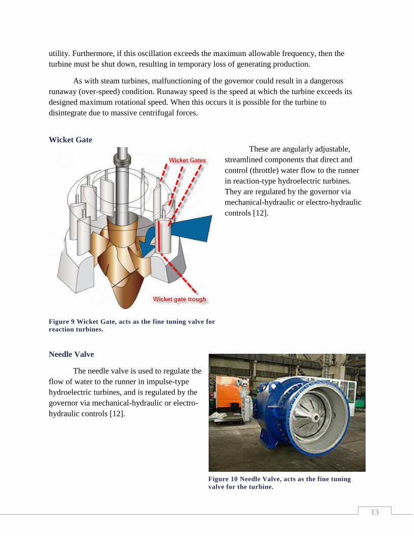
Wicket Gate
These are angularly adjustable,
streamlined components that direct and
control (throttle) water flow to the runner
in reaction-type hydroelectric turbines.
They are regulated by the governor via
mechanical-hydraulic or electro-hydraulic
controls [12].
Needle Valve
The needle valve is used to regulate the
flow of water to the runner in impulse-type
hydroelectric turbines, and is regulated by the
governor via mechanical-hydraulic or electro-
hydraulic controls [12].
Figure 9 Wicket Gate, acts as the fine tuning valve for
reaction turbines.
Figure 10 Needle Valve, acts as the fine tuning
valve for the turbine.

14
Inlet Valve
The inlet valve is located upstream of the turbine and is used to cut off the flow of water
in the event of an emergency or for maintenance. These valves are often spherical or butterfly
valves, and are usually operated by hydraulic power units [12] [13].
Building Materials
Under Ground
Building materials need to be able to withstand the test of time, especially ones that are
put in the ground. This is difficult for many types of material due to the moist environment and
lack of air. Wood has a tendency to rot and be eaten by insects. Steel loses its strength because of
rust and deterioration. The building materials that are commonly used for underground
construction are concrete and concrete blocks.
Formed Concrete
Concrete walls have many advantages for
underground construction. The solid walls are more
durable than other materials and water problems are
greatly reduced. Assembly time is much shorter
with poured walls which saves money by reducing
labor cost. Formed walls have some disadvantages
also. The forms used in construction are heavy and
can require a crane to put them in place. Another
disadvantage is concrete walls can crack. The use of
Figure 13 Formed concrete, while forms are
being removed
Figure 12 Butterfly inlet valve, controls the main
flow.
Figure 11 Radial inlet gate, the main inlet and
control valve on a dam.

15
horizontal and vertical reinforcements can reduce cracks and make the wall stronger. Many of
the cracks are superficial and do not go all the way through the wall. Cracks that do go all the
way through can be repaired with sealants made for this purpose. In 2012, the average cost of
constructing a concrete wall is approximately $4.35 per square foot [14].
Concrete Block
Concrete block construction has many of the
same advantages as poured concrete. It is good at
repelling water and has a long life span. Another
advantage of block is that they are light enough for a
person to lift. This makes a project easier to complete if a
crane is not available. Block walls can be made to have
close to the same strength as a poured wall if
reinforcement is used. This is done by placing rebar
down through the holes of the block and filling the holes
with concrete. There is also a metal mesh available that
can be placed on the joints where the mortar is placed to
hold the blocks together. These techniques combined can
give a block wall the strength of a poured wall but add
additional cost to the project. A disadvantage of a block wall is there are many joints. These
joints are weak spots that can deteriorate and let water leak through the wall. In 2012, the
average cost to install concrete block walls ranged from $5.41 to $7.17 per square foot [15].
Above Ground
Construction above ground will have many of the same elements as underground.
Concrete walls and block can be considered along with wood and steel for construction
materials. Above ground construction needs to take into consideration factors like weather,
appearance, usability, safety, and security.
Wood
Wood construction is the most common type of
construction today. Advantages of using wood include:
wood is a renewable resource, can be very energy efficient,
and is a common method of construction. Also many
people are familiar with working with wood and have the
tools needed. Disadvantages of wood are: it can have
natural flaws like knots that can reduce its strength, it can
decay if not treated, it is susceptible to insects, and it is
combustible. The average cost to build a wood frame shed is
$22.85 per square foot [16].
Figure 3 wood construction
Figure 14 Concrete block
Figure 15 Wood construction, the
most common type of construction

16
Steel
Steel frame construction is not as common as
wood but has some advantages. Steel is not combustible,
it is insect resistant, does not decay, and is very uniform
in strength. There are not as many contractors that work
with steel, so finding contractors is not as easy as with
wood. Disadvantages of steel are it is less energy
efficient, and it is susceptible to moisture because of
condensation. The average cost to build a steel frame
building is between $16.00 and $20.00 per square foot
[17].
Connecting the Generation Site to the Electrical Grid Network As shown in Figure 17, the United States and
Canada are split up into several regional grids. Each
region is directly connected via a grid network of
power distribution lines and generation facilities.
One region cannot connect directly to another region
as they are not in electrical phase with each other, so
a large phase-shifting transformer is placed at the
borders of each region to allow for power to flow
from one region to another.
An electrical grid network consists of
multiple electrical utilities with interconnections
between each utility. Each utility operates and
maintains their own network, but must maintain
considerations for neighboring utilities. For
example, a utility may operate at a lower voltage than its neighboring utility. To allow for
interconnection between the two utilities, a transformer must be placed at the interconnection
between the two utilities [18].
The facility at the wastewater treatment plant will generate electricity at approximately
2000 to 3000 volts. The electrical utilities in the surrounding area that the site could possibly
connect to are MP, Lake Country Power, and GRPUC.
MP owns a 115 kilovolt substation in southeast Grand Rapids. Power cables would need
to be run approximately 5000 feet between the generation site and the substation. Connection to
the substation could be made to the low or high voltage section of the substation.
Figure 17 Map of North American
electrical grid networks [19]
Figure 16 Steel Construction, stronger
and more resilient than wood, but is
not commonly used.
17
Lake Country Power owns a large electrical distribution network spanning much of
northeast Minnesota. This utility owns electrical power lines located near the wastewater
treatment plant which operate at 46 kilovolts.
GRPUC operates a 14 kilovolt electrical distribution network within the city limits of
Grand Rapids. Power lines from their network are located within 100 feet of the generation site,
making for a fairly easy connection to their grid.
Electrical Switchgear A variety of electrical switchgear is available on the market; this section will concentrate
on the switchgear required for the site.
Circuit Breakers
A main circuit breaker will be required to connect and disconnect the generator from the
electrical grid. For this project, medium voltage circuit breakers will be discussed. These circuit
breakers are constructed to operate at voltages from one to 72 kilovolts [19].
A circuit breaker serves several functions. It makes or breaks continuity between two
electrical circuits, it serves to protect equipment and personnel from electrical faults, and it
allows personnel to de-energize a piece of equipment for maintenance or other reasons.
There are several types of circuit breakers available, each with different features. Medium
voltage breakers can be classified into how the arc is extinguished within the circuit breaker:
Vacuum circuit breakers: These circuit breakers interrupt current by creating and
extinguishing the arc in a vacuum container. They are rated at up to approximately
35,000 volts and 3000 amps. They tend to have a longer life expectancy than air circuit
breakers due to reduced contact flashover [20].
Air circuit breakers: These circuit breakers extinguish the
electrical arc in an air filled environment. This type of circuit
breaker interrupts in air between two separable contacts with
the aid of magnetic blowout coils. When the circuit breaker
opens, the current carrying contacts separate and the arc is
drawn out horizontally and transferred to a set of arcing
contacts. Simultaneously, the blowout coil provides a
magnetic field to draw the arc upward into the arc chutes.
The arc accelerates upward into the arc chute where it is
extinguished [21].
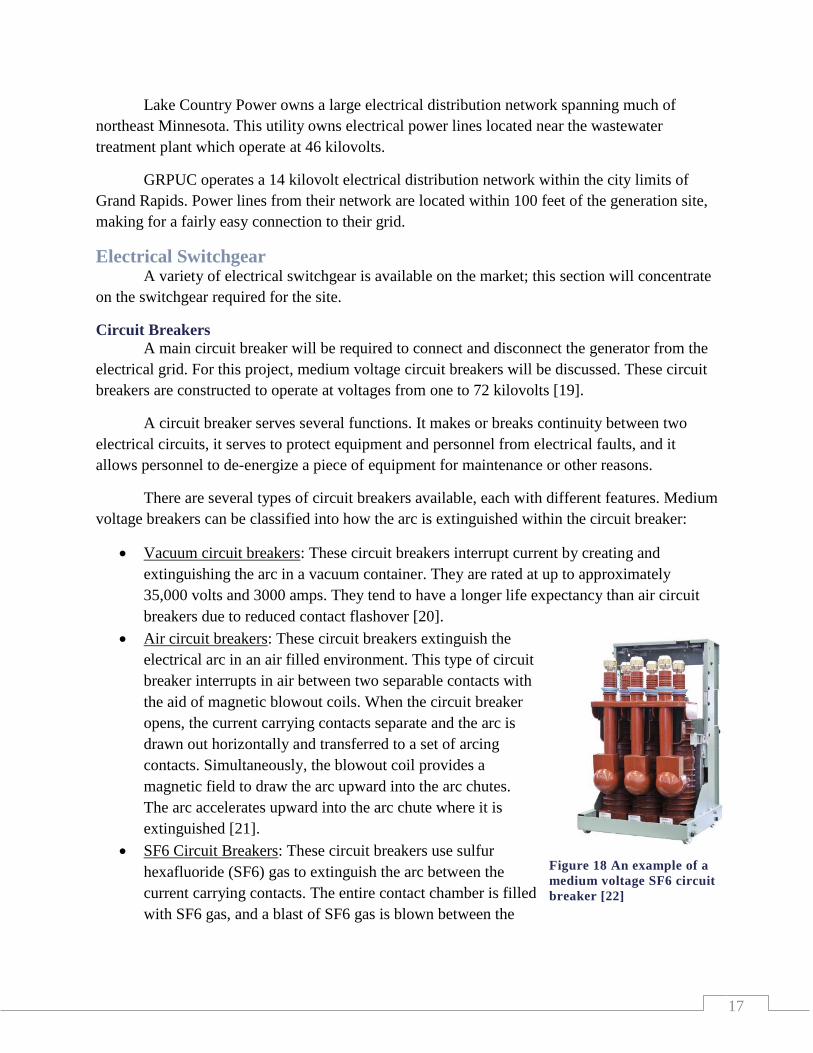
SF6 Circuit Breakers: These circuit breakers use sulfur
hexafluoride (SF6) gas to extinguish the arc between the
current carrying contacts. The entire contact chamber is filled
with SF6 gas, and a blast of SF6 gas is blown between the
Figure 18 An example of a
medium voltage SF6 circuit
breaker [22]
18
contacts during opening operations. This gas has excellent dielectric and arc quenching
properties [22].
Protective Relays
In addition to circuit breakers, protective relays are installed at generation sites to protect
all electrical equipment. These relays contain inputs from potential transformers, current
transformers, pressure sensors, temperature sensors, light sensors for arc flash, and vibration
sensors.
The relays monitor these inputs and calculate whether they are within specified ranges.
Fault conditions will drive the inputs out of preset ranges and cause the relay to initialize a
protective feature. This may be to open a circuit breaker, shut down an electrical generator, or to
alert personnel of a condition that is out of specification.
Most protective relays are microprocessor based and contain circuitry which monitors
conditions with a high degree of accuracy, data resolution, and a very low reaction time. This
allows for minimal damage to equipment and low danger to personnel during a fault condition by
removing the dangerous condition from the system. Several manufacturers produce protective
relays with a wide range of prices and features.
Transformers A transformer is a power converter that transfers electrical energy from one circuit to
another through inductively coupled conductors—the transformer's coils. A varying current in
the first or primary winding creates a varying magnetic flux in the transformer's core and thus a
varying magnetic field through the secondary winding. This varying magnetic field induces a
varying voltage, in the secondary winding. This effect is called inductive coupling [23].
By appropriate selection of the ratio of turns, a transformer enables an alternating
current (AC) voltage to be stepped up, or stepped down. The power is not changed and therefore
when the voltage goes up the current goes down, and vise-versa. The windings are coils usually
wound around a ferromagnetic core that is typically made of highly permeable silicon steel
laminated together. Each lamination is insulated from its neighbors by a thin non-conducting
layer of insulation. The steel has a permeability many times that of free space and the core serves
to greatly reduce the magnetizing current and confine the flux to a path which closely couples the
windings. Thinner laminations reduce losses, but are more laborious and expensive to
construct. Thin laminations are generally used on high frequency transformers, with some types
of very thin steel laminations able to operate up to 10 kHz. The effect of laminations is to
confine eddy currents to highly elliptical paths that contain little flux, reducing their magnitude
[24] [25].
All transformers operate on the same basic principles, although the range of designs
varies. Transformers are essential for high-voltage electric power transmission, which makes
long-distance transmission economically practical.

19
Fire and Electrical Codes This project required looking in to fire and electrical codes which will include NFPA 851
and NFPA 70E. Both of these codes describe fire prevention and mitigation of the effects of fire.
NFPA 851 is a publication from the National Fire Protection Association (NFPA) which
provides recommendations, not requirements, for fire prevention and fire protection for
hydroelectric generating plants. This includes a fire protection design process, general plant
design, fire protection systems and equipment, identification of and protection from hazards, fire
protection for the construction site, and a fire risk control program.
NFPA 70 is the National Electric Code, or the NEC. The general scope covered by this
series of documents covers the installation of electrical conductors, equipment, and raceways;
signaling and communications conductors, equipment, and raceways; and optical fiber cables
and raceways. This covers construction and operation of the hydro station building, generation
and switchgear equipment, and connection to the electrical grid [26].
Environmental impact statements An environmental impact statement (EIS) may be required for the hydro turbine project.
This document is required by the National Environmental Policy Act (NEPA) for certain actions
“significantly affecting the quality of the human environment” [27]. It provides information for
decision making and describes the negative and positive environmental effects of a proposed
action. Although during this project a preparation of this statement will not be completed, a short
summary of these statements is included below:
An EIS typically has four sections:
1) An introduction including a statement of the purpose and need of the proposed action or
project
2) A description of the affected environment.
3) A range of alternatives to the proposed action. These alternatives are considered the main
section of the EIS.
4) An analysis of the environmental impacts of each of the possible alternatives. This
section covers topics such as:
Impacts to threatened or endangered species
Air and water quality impacts
Impacts to historic and cultural sites, (particularly sites of significant importance
to Native American tribes)
Social and Economic impacts to local communities
Cost analysis for each alternative, including costs to mitigate expected impacts, to
determine if the proposed action is a prudent use of taxpayer dollars
Environmental Regulations Environmental laws and statutes cover a wide array of subjects and are enforced by
federal, state, and local governments. The purpose of these regulations is to regulate activities

20
that have an environmental impact on their surroundings. Furthermore, the mission of the
regulations is to protect human health and the environment [27].
The major environmental issue the team will consider for this project will be constructing
a structure in close vicinity to the Mississippi river. The majority of the regulations for this
project are covered under Minnesota statues and regulations. A summary of some of the
applicable regulations are covered in the following
section.
Minnesota Department of Natural Resources
(MNDNR) specifies setback requirements for
structures built on lakes and rivers. A minimum
distance must be kept from the shoreline based upon
lot width, shoreline type, and structure type. In
addition, no building may be placed within a
floodplain of a lake or river. In accordance with
Minnesota Department of Natural Resources
‘Shoreland Management Rules’ Chapter 6120, setback
requirements for placement of a structure from a bluff
require a building to be placed no less than 30 feet
from the edge of a bluff. The hydrostation building will
be placed near the bluff of the Mississippi River and
will follow this setback requirement [28] [29].
While water runoff into the river is natural and
inevitable, erosion from shoreline can occur. This creates sediment runoff into the water
degrading water quality. Standards are set by the Minnesota Pollution Control Agency (MPCA)
to minimize unfiltered water flow into waterways. Mitigation methods include ensuring natural
vegetation is kept along the shores of the water ways. Also during unavoidable disturbance of the
soil, techniques are employed to filter any water runoff. The MPCA has produced a handbook
describing these rules and regulations call the ‘Stormwater Best Management Practices Manual’
which the team will follow for the project [30].
Under Minnesota state law, the floodplain is considered to be the land adjoining lakes
and rivers that is covered by the "100-year" or "regional" flood. This area has special restrictions
for building permanent structures within this floodplain [28].
Wastewater Regulations There are many regulations concerning wastewater treatment systems. The Minnesota
Pollution Control Agency (MPCA) is in charge of instituting the regulations and making sure the
Figure 19 Overhead view of the building
site with the Mississippi River to the right.
21
regulations are being followed. The specific wastewater
regulations that are important to this project concern the
amount of chemicals and water that are being discharged from
the plant. The last stage of the wastewater treatment process is
to treat the water with chlorine; this kills the remaining bacteria
used in the process. The regulations require the chlorine to be
dissipated before leaving the holding ponds. Since water flow
may change due to this project, testing will have to be done to
make sure the state requirements can still be met. This testing is
currently done using the daily average amount of water leaving the plant. Since the team’s
project involves the hydroelectric plant only, regulations for wastewater discharge are beyond
the scope of the project.
Zoning and Building Codes This project requires looking into the building and zoning codes that the City of Grand
Rapids requires. The city of Grand Rapids has adopted the State of Minnesota’s building code
system and the shore land use standards. The State of Minnesota follows Chapter 326B
Construction Codes and Licensing statutes for building projects.
In order to put a building on the proposed sight, it has to meet zoning codes. A building
suitable to meet the project requirements would be considered an essential service structure; it
would require a conditional use permit. A conditional use permit cost $505.00. The main codes
for an essential service building refer to setbacks from the right of way, the river, and side
properties. In addition, it has to aesthetically fit in with the surrounding buildings in the
neighborhood. A distance of thirty feet from the right of way is required. A distance of fifteen
feet from the side properties is required. The river setbacks are fifty feet from the ordinary high
water mark and thirty feet from the top of the bluff. A variance permit will be needed if any of
these requirements cannot be met. The proposed variance will have to be reviewed and approved
by the zoning board for the project to proceed. A variance permit cost is $252.50 [31].
The project will require a building permit for the proposed structure. The cost of a
building permit is dependent on the cost of the proposed building project. The structure will be
engineered to meet Minnesota’s standard building codes. Some of the codes relate to snow load,
exit size, lighting, fire extinguishers, and ventilation. The City of Grand Rapids has a building
inspector who would inspect the work and make sure the building meets the requirements.
If the proposed project requires any work to be done on the river bank or in the water, a
permit may be required from the Minnesota Department of Natural Resources. The permits are
issued based on a case by case analysis.
Selling Electrical Power Since the initial estimates of power generation are not above GRPUC’s power demands,
the client would not be selling power outright. Instead they will be decreasing the amount of
Figure 20 MPCA logo

22
power they are demanding. Decreasing the amount of power demanded will decrease the cost
they have to pay for electricity and that cost savings can be considered revenue for purposes of
this project.
A power generation site over 5 megawatts capacity is considered to be “before the meter”
power generation and are regulated by the Midwest Independent Transmission System Operator,
Inc. (MISO), a conglomerate of power companies in the Midwest part of the United States.
These sites are directed when to generate power, and when to remain offline based on their
individual cost of generation. Generally less costly generation sites will operate more than other
sites. Generators under 5 megawatts capacity are considered “behind the meter” generators and
can run continually. They decrease the load of the system rather than providing power for the
load. The proposed generator at the wastewater treatment plant will produce a maximum of 70
kilowatts and will be a “behind the meter” system [32].
The cost of power varies every five minutes with a wide spread based on hourly, daily,
monthly, and yearly demands and available supply. The since there is more demand during the
16 hours that people are generally awake, the cost rises to about double what the off peak cost is.
Usually the cost of electricity increases during the winter months due to increased heating costs.
It will be possible to vary the amount of water that will be let down the pipe into the
generator; storing energy during the night and releasing it during the day. Using this, the client
will be able to increase the amount of power savings they will receive.
Financing
Financing for this project could come from three main areas: grants, loans, and funds
currently available. Grants are a source of money that comes from private organizations or the
government to be used on a specific project; this money does not have to be repaid. Loans are a
monetary source that would allow money to be spent now and repaid at a later date. There are
also funds from GRPUC that would be available for conservation projects.
Grants
There are financial grants from both the state and the federal governments [33] [34]. State
based funding relies mostly on the region that someone is working in. Since this project takes
place in the MP region, their grant could be applied for. Their grant allows for up to $50,000 to
help pay for projects like this one [35]. Their current grant period will end on December 31,
2012 [35], however a new cycle may begin the year after. Excel Energy also funds renewable
energy projects in Minnesota through their Renewable Development Fund [36]. This fund is
currently not accepting applicants, but may be a source of funding in the future [37]. Federal
grants are designed mostly for companies that pay taxes. Since the GRPUC is a governmental
body, they are not able to apply for the current federal program (U.S. Department of Treasury -
Renewable Energy Grants) that helps to create renewable energy facilities [38].

23
Loans
Loans would be given to the GRPUC from the city so the interest rate would be 5%
which is the commission’s acceptable rate of return. These loans would need to be able to be
paid off by either the savings gained from the generator or from the budgeted available
resources.
Available resources
The GRPUC has a budget that can be spent on conservation projects. Since this project
will reduce the amount of energy used, this project could be paid for with that money. Currently
the conservation project budget is 1.5% of $13.3 million, or $199,105 [39]. It may be possible
that the GRPUC could spend more than that budgeted amount.
Options
Summary This section will discuss all solutions to the project the team brainstormed and
investigated including ideas discussed in the background research section. An initial discussion
is included for each option. Decision matrices were used to weigh all options either by using a
weighted scale system or the Pugh method. Final decisions for each option are included.
Turbines The team looked into three types of turbines: Francis, Pelton, and Kaplan. Because of the
calculated energy output the turbines considered for this project will be on the micro scale level,
or less than 100 kilowatts. The criteria that went into the teams decisions included:
Cost – How much it will cost for each option.
Efficiency – Determining how well the turbine works for the conditions.
Life span – Determining how long the turbine will be useful.
Maintenance – Looking at how much maintenance each type will require.
Manufacturer’s recommendations –The turbine manufacturers recommend for the
system.
Table 1 A weighted table for the options of turbine
Turbines
Impact Level (1 = Not recommended, 2 = Acceptable,
3 = Recommended)
Francis Pelton Kaplan
Cost 2 2 2
Efficiencies 3 1 3
Life Span 3 3 3
Maintenance 3 1 2
Manufacture Recommendation 3 1 2
Totals 14 8 12

24
The Francis turbine’s advantages are: high efficiency, ability to handle varying flows, and
it works with lower head and higher flows compared to the Pelton. A disadvantage is the Francis
turbine requires an enclosed pressurized housing. This can add cost to the project if the piping
system must be redesigned.
The Pelton turbine’s advantages include: it does not need to have an enclosed pressurized
system, it requires a small housing, and it has the ability to withstand varying flows. The main
disadvantage of the Pelton is it requires a large difference in height from the beginning of the
system to the end of the system of at least 300 feet. Because the height difference is
approximately 50 feet, the amount of pressure head is not sufficient for this type of turbine. Also,
the nozzles of this type of turbine require more maintenance.
The Kaplan turbine’s advantages are similar to the Francis. It works best with a high flow
and low pressure head and is built to handle more debris and sand than other turbines. The
Kaplan has adjustable gates and wickets which aid in its ability to have better efficiencies. These
adjustable parts also produce more maintenance.
The manufacturer’s recommendations are determined by the flow and the height of the
systems. The maintenance is based on the number and design of parts, such as nozzles and
wicket gates. The life expectancy and cost of the turbines were about the same. The team chose
to use the Francis turbine based upon manufacturer’s recommendations and its application to the
site based upon total head and water flow rate [6] [7].
Pipe Construction Four options were chosen for the effluent pipe from the wastewater treatment plant to the
turbines: reuse the existing pipe, reline the existing pipe, install a new pipe, and slip the existing
pipe with a smaller pipe. The criteria for the team’s decision were:
Price – How much it will cost for each option.
Complexity – How complex each option will be to install.
Ease of Install – How difficult each option will be to install.
Life expectancy – Looking at whether the pipe will have to be replaced over the lifetime
of the generation site.
Headloss (pipe size) – Determining if the size of the pipe have to be reduced from the
original pipe size.
Headloss (pipe type) – How the coefficient of friction affects the system.
Client recommendation – This was not considered in decision matrix, but it was worth
noting.
25
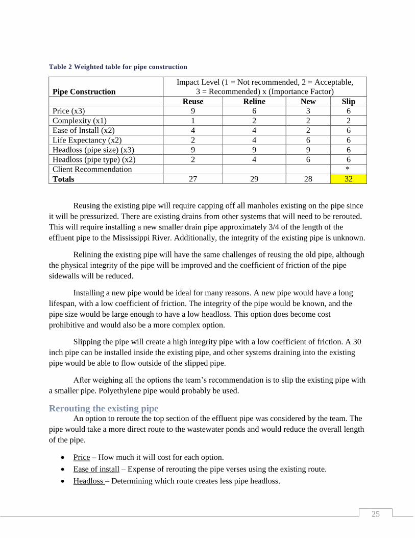
Table 2 Weighted table for pipe construction
Pipe Construction
Impact Level (1 = Not recommended, 2 = Acceptable,
3 = Recommended) x (Importance Factor)
Reuse Reline New Slip
Price (x3) 9 6 3 6
Complexity (x1) 1 2 2 2
Ease of Install (x2) 4 4 2 6
Life Expectancy (x2) 2 4 6 6
Headloss (pipe size) (x3) 9 9 9 6
Headloss (pipe type) (x2) 2 4 6 6
Client Recommendation *
Totals 27 29 28 32
Reusing the existing pipe will require capping off all manholes existing on the pipe since
it will be pressurized. There are existing drains from other systems that will need to be rerouted.
This will require installing a new smaller drain pipe approximately 3/4 of the length of the
effluent pipe to the Mississippi River. Additionally, the integrity of the existing pipe is unknown.
Relining the existing pipe will have the same challenges of reusing the old pipe, although
the physical integrity of the pipe will be improved and the coefficient of friction of the pipe
sidewalls will be reduced.
Installing a new pipe would be ideal for many reasons. A new pipe would have a long
lifespan, with a low coefficient of friction. The integrity of the pipe would be known, and the
pipe size would be large enough to have a low headloss. This option does become cost
prohibitive and would also be a more complex option.
Slipping the pipe will create a high integrity pipe with a low coefficient of friction. A 30
inch pipe can be installed inside the existing pipe, and other systems draining into the existing
pipe would be able to flow outside of the slipped pipe.
After weighing all the options the team’s recommendation is to slip the existing pipe with
a smaller pipe. Polyethylene pipe would probably be used.
Rerouting the existing pipe An option to reroute the top section of the effluent pipe was considered by the team. The
pipe would take a more direct route to the wastewater ponds and would reduce the overall length
of the pipe.
Price – How much it will cost for each option.
Ease of install – Expense of rerouting the pipe verses using the existing route.
Headloss – Determining which route creates less pipe headloss.
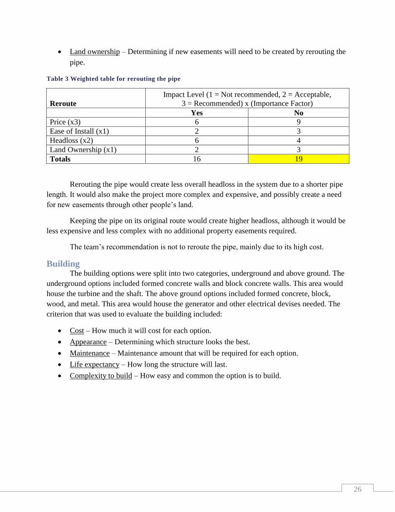
26
Land ownership – Determining if new easements will need to be created by rerouting the
pipe.
Table 3 Weighted table for rerouting the pipe
Reroute
Impact Level (1 = Not recommended, 2 = Acceptable,
3 = Recommended) x (Importance Factor)
Yes No
Price (x3) 6 9
Ease of Install (x1) 2 3
Headloss (x2) 6 4
Land Ownership (x1) 2 3
Totals 16 19
Rerouting the pipe would create less overall headloss in the system due to a shorter pipe
length. It would also make the project more complex and expensive, and possibly create a need
for new easements through other people’s land.
Keeping the pipe on its original route would create higher headloss, although it would be
less expensive and less complex with no additional property easements required.
The team’s recommendation is not to reroute the pipe, mainly due to its high cost.
Building The building options were split into two categories, underground and above ground. The
underground options included formed concrete walls and block concrete walls. This area would
house the turbine and the shaft. The above ground options included formed concrete, block,
wood, and metal. This area would house the generator and other electrical devises needed. The
criterion that was used to evaluate the building included:
Cost – How much it will cost for each option.
Appearance – Determining which structure looks the best.
Maintenance – Maintenance amount that will be required for each option.
Life expectancy – How long the structure will last.
Complexity to build – How easy and common the option is to build.
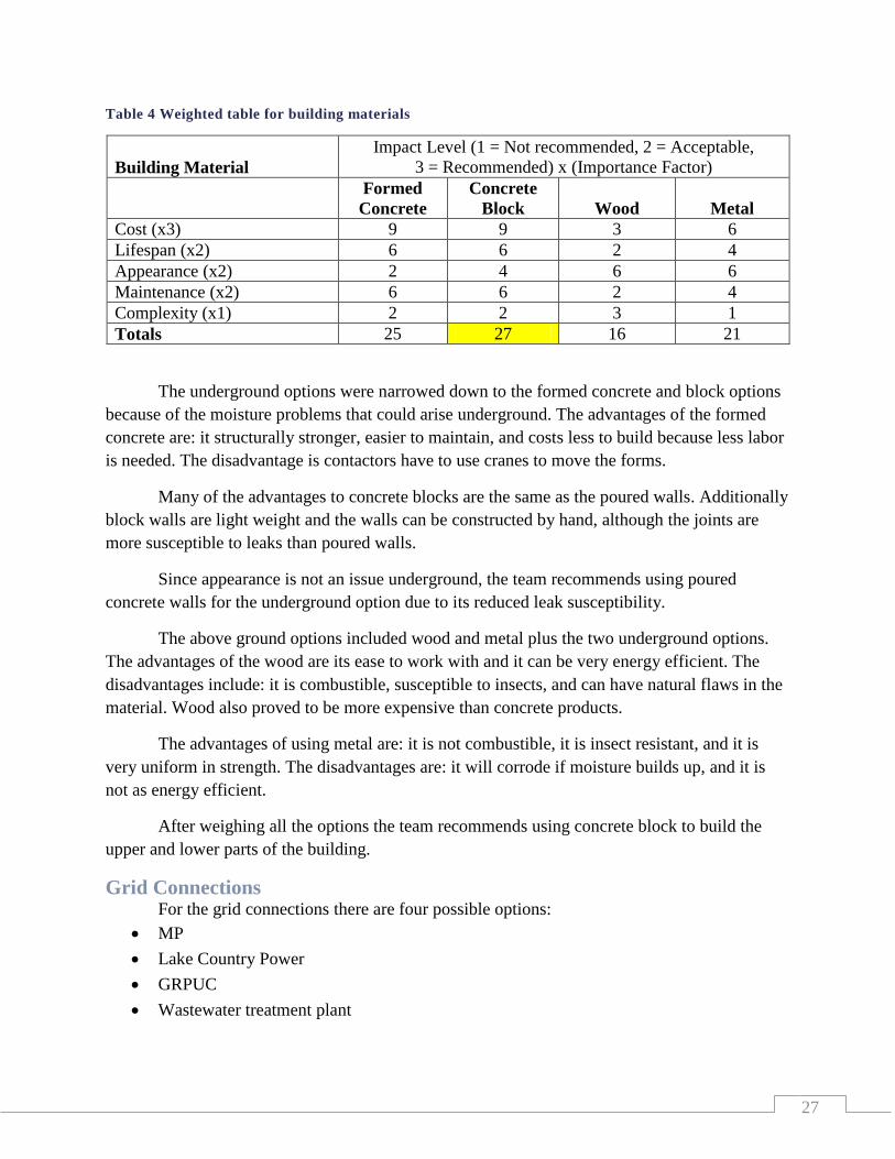
27
Table 4 Weighted table for building materials
Building Material
Impact Level (1 = Not recommended, 2 = Acceptable,
3 = Recommended) x (Importance Factor)
Formed
Concrete
Concrete
Block Wood Metal
Cost (x3) 9 9 3 6
Lifespan (x2) 6 6 2 4
Appearance (x2) 2 4 6 6
Maintenance (x2) 6 6 2 4
Complexity (x1) 2 2 3 1
Totals 25 27 16 21
The underground options were narrowed down to the formed concrete and block options
because of the moisture problems that could arise underground. The advantages of the formed
concrete are: it structurally stronger, easier to maintain, and costs less to build because less labor
is needed. The disadvantage is contactors have to use cranes to move the forms.
Many of the advantages to concrete blocks are the same as the poured walls. Additionally
block walls are light weight and the walls can be constructed by hand, although the joints are
more susceptible to leaks than poured walls.
Since appearance is not an issue underground, the team recommends using poured
concrete walls for the underground option due to its reduced leak susceptibility.
The above ground options included wood and metal plus the two underground options.
The advantages of the wood are its ease to work with and it can be very energy efficient. The
disadvantages include: it is combustible, susceptible to insects, and can have natural flaws in the
material. Wood also proved to be more expensive than concrete products.
The advantages of using metal are: it is not combustible, it is insect resistant, and it is
very uniform in strength. The disadvantages are: it will corrode if moisture builds up, and it is
not as energy efficient.
After weighing all the options the team recommends using concrete block to build the
upper and lower parts of the building.
Grid Connections For the grid connections there are four possible options:
MP
Lake Country Power
GRPUC
Wastewater treatment plant
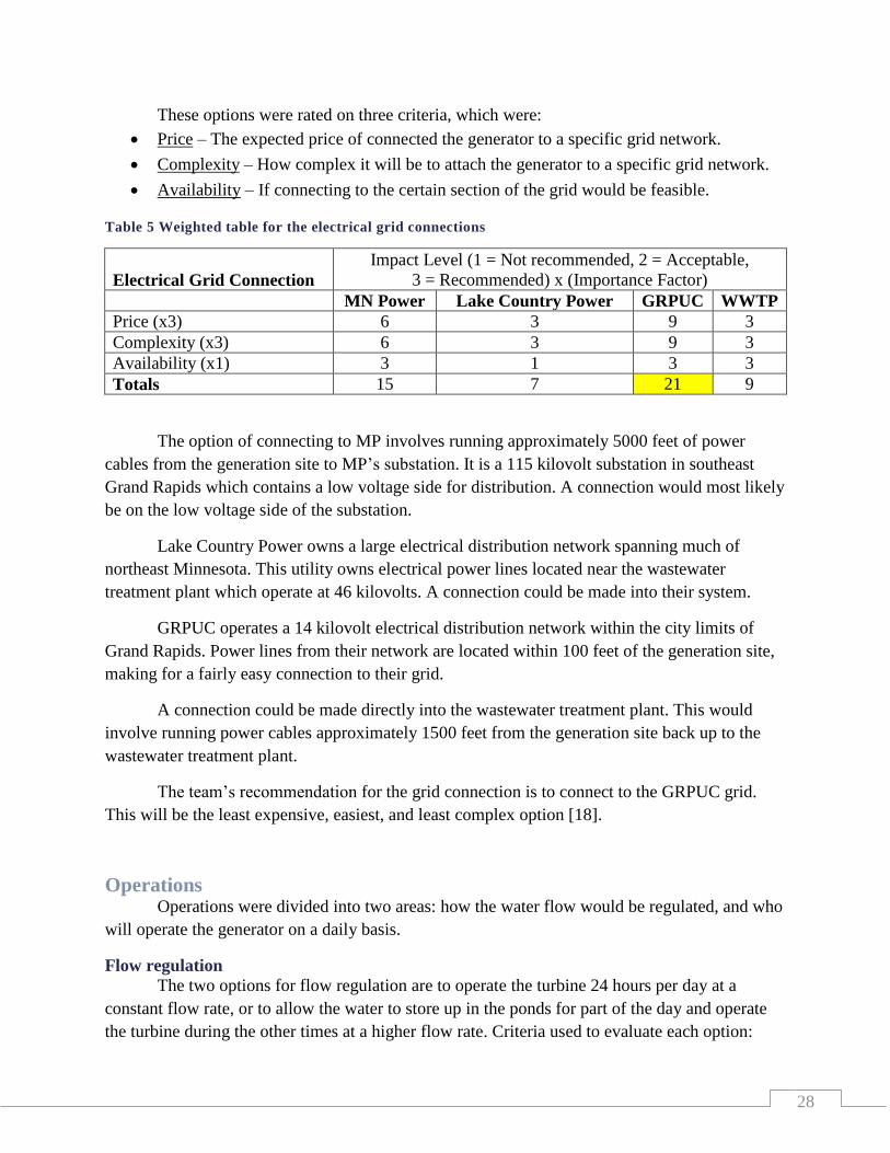
28
These options were rated on three criteria, which were:
Price – The expected price of connected the generator to a specific grid network.
Complexity – How complex it will be to attach the generator to a specific grid network.
Availability – If connecting to the certain section of the grid would be feasible.
Table 5 Weighted table for the electrical grid connections
Electrical Grid Connection
Impact Level (1 = Not recommended, 2 = Acceptable,
3 = Recommended) x (Importance Factor)
MN Power Lake Country Power GRPUC WWTP
Price (x3) 6 3 9 3
Complexity (x3) 6 3 9 3
Availability (x1) 3 1 3 3
Totals 15 7 21 9
The option of connecting to MP involves running approximately 5000 feet of power
cables from the generation site to MP’s substation. It is a 115 kilovolt substation in southeast
Grand Rapids which contains a low voltage side for distribution. A connection would most likely
be on the low voltage side of the substation.
Lake Country Power owns a large electrical distribution network spanning much of
northeast Minnesota. This utility owns electrical power lines located near the wastewater
treatment plant which operate at 46 kilovolts. A connection could be made into their system.
GRPUC operates a 14 kilovolt electrical distribution network within the city limits of
Grand Rapids. Power lines from their network are located within 100 feet of the generation site,
making for a fairly easy connection to their grid.
A connection could be made directly into the wastewater treatment plant. This would
involve running power cables approximately 1500 feet from the generation site back up to the
wastewater treatment plant.
The team’s recommendation for the grid connection is to connect to the GRPUC grid.
This will be the least expensive, easiest, and least complex option [18].
Operations Operations were divided into two areas: how the water flow would be regulated, and who
will operate the generator on a daily basis.
Flow regulation
The two options for flow regulation are to operate the turbine 24 hours per day at a
constant flow rate, or to allow the water to store up in the ponds for part of the day and operate
the turbine during the other times at a higher flow rate. Criteria used to evaluate each option:
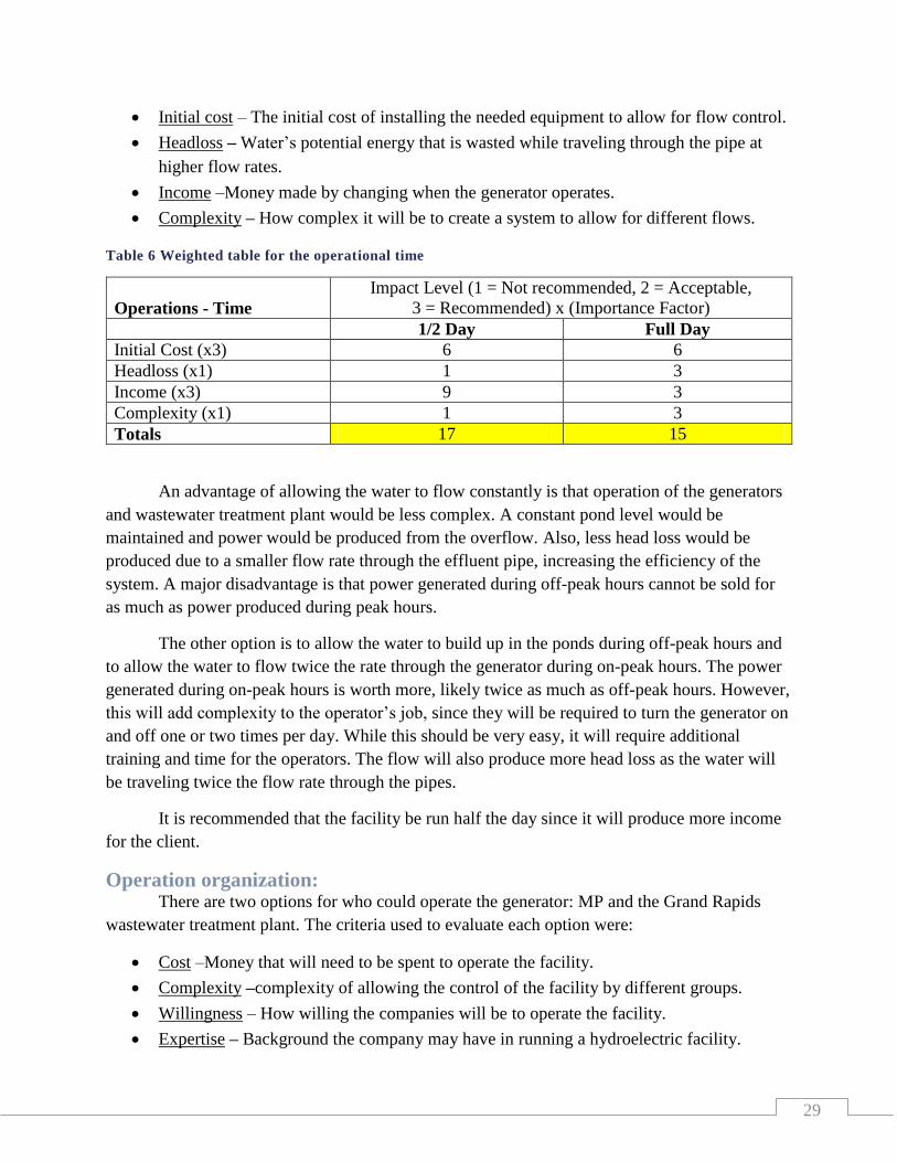
29
Initial cost – The initial cost of installing the needed equipment to allow for flow control.
Headloss – Water’s potential energy that is wasted while traveling through the pipe at
higher flow rates.
Income –Money made by changing when the generator operates.
Complexity – How complex it will be to create a system to allow for different flows.
Table 6 Weighted table for the operational time
Operations - Time
Impact Level (1 = Not recommended, 2 = Acceptable,
3 = Recommended) x (Importance Factor)
1/2 Day Full Day
Initial Cost (x3) 6 6
Headloss (x1) 1 3
Income (x3) 9 3
Complexity (x1) 1 3
Totals 17 15
An advantage of allowing the water to flow constantly is that operation of the generators
and wastewater treatment plant would be less complex. A constant pond level would be
maintained and power would be produced from the overflow. Also, less head loss would be
produced due to a smaller flow rate through the effluent pipe, increasing the efficiency of the
system. A major disadvantage is that power generated during off-peak hours cannot be sold for
as much as power produced during peak hours.
The other option is to allow the water to build up in the ponds during off-peak hours and
to allow the water to flow twice the rate through the generator during on-peak hours. The power
generated during on-peak hours is worth more, likely twice as much as off-peak hours. However,
this will add complexity to the operator’s job, since they will be required to turn the generator on
and off one or two times per day. While this should be very easy, it will require additional
training and time for the operators. The flow will also produce more head loss as the water will
be traveling twice the flow rate through the pipes.
It is recommended that the facility be run half the day since it will produce more income
for the client.
Operation organization: There are two options for who could operate the generator: MP and the Grand Rapids
wastewater treatment plant. The criteria used to evaluate each option were:
Cost –Money that will need to be spent to operate the facility.
Complexity –complexity of allowing the control of the facility by different groups.
Willingness – How willing the companies will be to operate the facility.
Expertise – Background the company may have in running a hydroelectric facility.
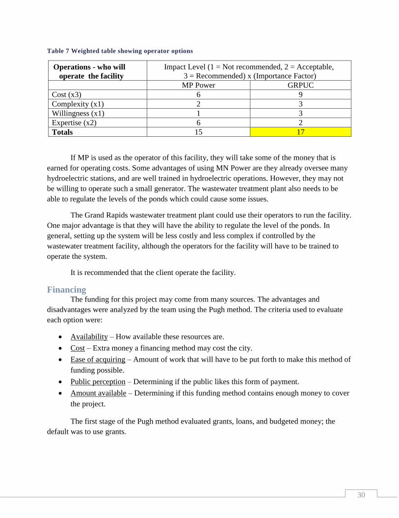
30
Table 7 Weighted table showing operator options
Operations - who will
operate the facility
Impact Level (1 = Not recommended, 2 = Acceptable,
3 = Recommended) x (Importance Factor)
MP Power GRPUC
Cost (x3) 6 9
Complexity (x1) 2 3
Willingness (x1) 1 3
Expertise (x2) 6 2
Totals 15 17
If MP is used as the operator of this facility, they will take some of the money that is
earned for operating costs. Some advantages of using MN Power are they already oversee many
hydroelectric stations, and are well trained in hydroelectric operations. However, they may not
be willing to operate such a small generator. The wastewater treatment plant also needs to be
able to regulate the levels of the ponds which could cause some issues.
The Grand Rapids wastewater treatment plant could use their operators to run the facility.
One major advantage is that they will have the ability to regulate the level of the ponds. In
general, setting up the system will be less costly and less complex if controlled by the
wastewater treatment facility, although the operators for the facility will have to be trained to
operate the system.
It is recommended that the client operate the facility.
Financing The funding for this project may come from many sources. The advantages and
disadvantages were analyzed by the team using the Pugh method. The criteria used to evaluate
each option were:
Availability – How available these resources are.
Cost – Extra money a financing method may cost the city.
Ease of acquiring – Amount of work that will have to be put forth to make this method of
funding possible.
Public perception – Determining if the public likes this form of payment.
Amount available – Determining if this funding method contains enough money to cover
the project.
The first stage of the Pugh method evaluated grants, loans, and budgeted money; the
default was to use grants.
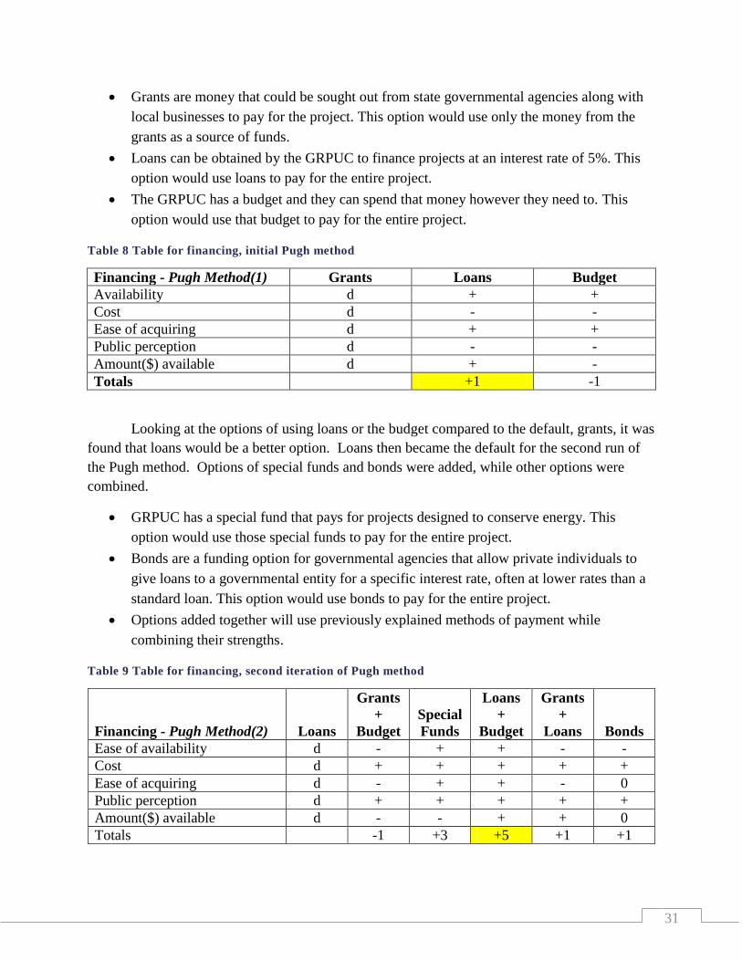
31
Grants are money that could be sought out from state governmental agencies along with
local businesses to pay for the project. This option would use only the money from the
grants as a source of funds.
Loans can be obtained by the GRPUC to finance projects at an interest rate of 5%. This
option would use loans to pay for the entire project.
The GRPUC has a budget and they can spend that money however they need to. This
option would use that budget to pay for the entire project.
Table 8 Table for financing, initial Pugh method
Financing - Pugh Method(1) Grants Loans Budget
Availability d + +
Cost d - -
Ease of acquiring d + +
Public perception d - -
Amount($) available d + -
Totals +1 -1
Looking at the options of using loans or the budget compared to the default, grants, it was
found that loans would be a better option. Loans then became the default for the second run of
the Pugh method. Options of special funds and bonds were added, while other options were
combined.
GRPUC has a special fund that pays for projects designed to conserve energy. This
option would use those special funds to pay for the entire project.
Bonds are a funding option for governmental agencies that allow private individuals to
give loans to a governmental entity for a specific interest rate, often at lower rates than a
standard loan. This option would use bonds to pay for the entire project.
Options added together will use previously explained methods of payment while
combining their strengths.
Table 9 Table for financing, second iteration of Pugh method
Financing - Pugh Method(2) Loans
Grants
+
Budget
Special
Funds
Loans
+
Budget
Grants
+
Loans Bonds
Ease of availability d - + + - -
Cost d + + + + +
Ease of acquiring d - + + - 0
Public perception d + + + + +
Amount($) available d - - + + 0
Totals -1 +3 +5 +1 +1
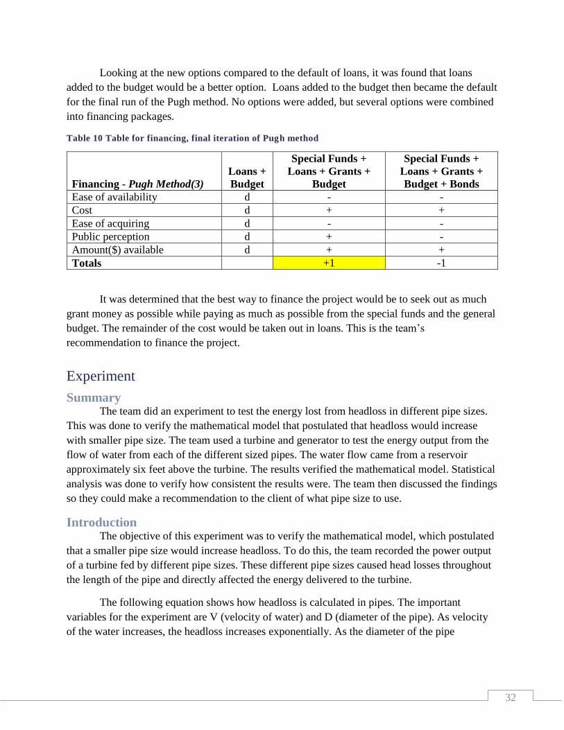
32
Looking at the new options compared to the default of loans, it was found that loans
added to the budget would be a better option. Loans added to the budget then became the default
for the final run of the Pugh method. No options were added, but several options were combined
into financing packages.
Table 10 Table for financing, final iteration of Pugh method
Financing - Pugh Method(3)
Loans +
Budget
Special Funds +
Loans + Grants +
Budget
Special Funds +
Loans + Grants +
Budget + Bonds
Ease of availability d - -
Cost d + +
Ease of acquiring d - -
Public perception d + -
Amount($) available d + +
Totals +1 -1
It was determined that the best way to finance the project would be to seek out as much
grant money as possible while paying as much as possible from the special funds and the general
budget. The remainder of the cost would be taken out in loans. This is the team’s
recommendation to finance the project.
Experiment
Summary The team did an experiment to test the energy lost from headloss in different pipe sizes.
This was done to verify the mathematical model that postulated that headloss would increase
with smaller pipe size. The team used a turbine and generator to test the energy output from the
flow of water from each of the different sized pipes. The water flow came from a reservoir
approximately six feet above the turbine. The results verified the mathematical model. Statistical
analysis was done to verify how consistent the results were. The team then discussed the findings
so they could make a recommendation to the client of what pipe size to use.
Introduction The objective of this experiment was to verify the mathematical model, which postulated
that a smaller pipe size would increase headloss. To do this, the team recorded the power output
of a turbine fed by different pipe sizes. These different pipe sizes caused head losses throughout
the length of the pipe and directly affected the energy delivered to the turbine.
The following equation shows how headloss is calculated in pipes. The important
variables for the experiment are V (velocity of water) and D (diameter of the pipe). As velocity
of the water increases, the headloss increases exponentially. As the diameter of the pipe

33
decreases, the headloss of the pipe also increases. These factors will be proven in the experiment
and the mathematical model.
Equation 2 Headloss of a fluid through a pipe
Various fluids textbooks were reviewed prior to the experiment including “Core
Engineering Concepts” textbook. Pressure of fluid vs. height, headloss, kinetic energy of fluids,
and turbines were reviewed.
A hydraulic turbine generator system will be simulated in this experiment. A constant
pressure height will be achieved and will not be changed. The turbine will be operated at
maximum output with no limitations to flow. The generator will produce a power output at an
unregulated speed and voltage with a constant load attached. None of the generator variables will
be changed. The pipe lengths will all be approximately 10 feet long, and will not be varied. The
changing variable will be the pipe size. 1/2”, 3/4”, and 1” pipe sizes will be used for the
experiment.
Apparatus
A turbine was needed for the experiment. The team looked to purchase an inexpensive
turbine, but could not find any. The team then looked to see if any pumps could be used
backwards, to act as a turbine. One option was found that could output a little energy, but this
option was very inefficient, so the team decided to pursue creating their own turbine.
Figure 21 Side view of all components cut for the turbine.
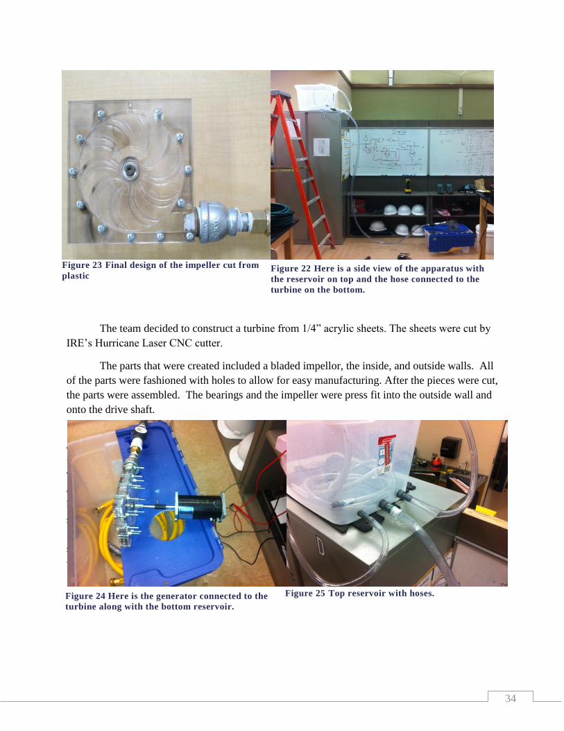
34
Figure 23 Final design of the impeller cut from
plastic
The team decided to construct a turbine from 1/4” acrylic sheets. The sheets were cut by
IRE’s Hurricane Laser CNC cutter.
The parts that were created included a bladed impellor, the inside, and outside walls. All
of the parts were fashioned with holes to allow for easy manufacturing. After the pieces were cut,
the parts were assembled. The bearings and the impeller were press fit into the outside wall and
onto the drive shaft.
A ten gallon capacity clear plastic tub was used for the upper reservoir. Three holes were
drilled into the bottom portion of the tub to allow for different sizes of pipes to be attached to the
tub. 1/2”, 3/4”, and 1” clear plastic hoses approximately 10 feet long were attached to the tub.
This tub was placed approximately 8 feet above the floor. The turbine was placed above a second
clear plastic reservoir on the floor. A 12VDC water pump was used to pump this water from the
bottom tub to the top tub. The hoses were connected to the turbine with a one inch ball valve to
shut the water off and on. A 12VDC generator was connected to the turbine with a slip collar. A
10 ohm resistor was connected to the generator for a load with a digital ammeter connected in
series with the load. A digital voltmeter was connected across the generator terminals to monitor
voltage.
Figure 22 Here is a side view of the apparatus with
the reservoir on top and the hose connected to the
turbine on the bottom.
Figure 24 Here is the generator connected to the
turbine along with the bottom reservoir.
Figure 25 Top reservoir with hoses.
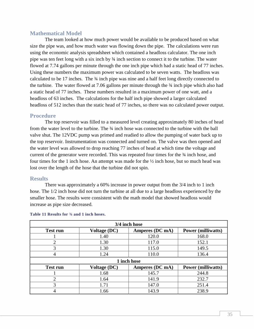
35
Mathematical Model The team looked at how much power would be available to be produced based on what
size the pipe was, and how much water was flowing down the pipe. The calculations were run
using the economic analysis spreadsheet which contained a headloss calculator. The one inch
pipe was ten feet long with a six inch by ¾ inch section to connect it to the turbine. The water
flowed at 7.74 gallons per minute through the one inch pipe which had a static head of 77 inches.
Using these numbers the maximum power was calculated to be seven watts. The headloss was
calculated to be 17 inches. The ¾ inch pipe was nine and a half feet long directly connected to
the turbine. The water flowed at 7.06 gallons per minute through the ¾ inch pipe which also had
a static head of 77 inches. These numbers resulted in a maximum power of one watt, and a
headloss of 63 inches. The calculations for the half inch pipe showed a larger calculated
headloss of 512 inches than the static head of 77 inches, so there was no calculated power output.
Procedure The top reservoir was filled to a measured level creating approximately 80 inches of head
from the water level to the turbine. The ¾ inch hose was connected to the turbine with the ball
valve shut. The 12VDC pump was primed and readied to allow the pumping of water back up to
the top reservoir. Instrumentation was connected and turned on. The valve was then opened and
the water level was allowed to drop reaching 77 inches of head at which time the voltage and
current of the generator were recorded. This was repeated four times for the ¾ inch hose, and
four times for the 1 inch hose. An attempt was made for the ½ inch hose, but so much head was
lost over the length of the hose that the turbine did not spin.
Results There was approximately a 60% increase in power output from the 3/4 inch to 1 inch
hose. The 1/2 inch hose did not turn the turbine at all due to a large headloss experienced by the
smaller hose. The results were consistent with the math model that showed headloss would
increase as pipe size decreased.
Table 11 Results for ¾ and 1 inch hoses.
3/4 inch hose
Test run Voltage (DC) Amperes (DC mA) Power (milliwatts)
1 1.40 120.0 168.0
2 1.30 117.0 152.1
3 1.30 115.0 149.5
4 1.24 110.0 136.4
1 inch hose
Test run Voltage (DC) Amperes (DC mA) Power (milliwatts)
1 1.68 145.7 244.8
2 1.64 141.9 232.7
3 1.71 147.0 251.4
4 1.66 143.9 238.9

36
Statistical Analysis The team used Microsoft’s Excel program to do a descriptive statistical analysis of the
data it received from doing the experiment. The reason this was done was to analyze the
variability of the data. The variability ended up being 6.38x10⁻⁵
for the one inch hose and
1.6x10⁻⁴
for the ¾ inch hose. The standard deviation ended up being 7.98x10⁻³
for the one inch
hose and 1.29x10⁻²
for the ¾ inch hose while using a confidence level of 90%. This data can be
seen in Table 12. This showed that the results were very consistent within each sample set.
After going through the criteria for what test to use, it was decided that the Pearson
Correlation test was the best option to use. The Pearson Correlation shows the correlation
between a dependent variable and an independent variable. The dependent variable was the
power output from the turbine/generator; the independent variable was the size of the pipe. The
team used Microsoft Excel to compute this data. The computed correlation coefficient shows
how much correlation there is between the variables. A coefficient of one means that there is a
perfect correlation between the variables and zero means there is no correlation. The correlation
coefficient for this experiment was 0.979 which showed a strong positive correlation between
pipe size and the amount of power output from the turbine/generator. This result was graphed to
show the correlation. This also supports the teams hypothesis that as pipe size increases so would
the power.
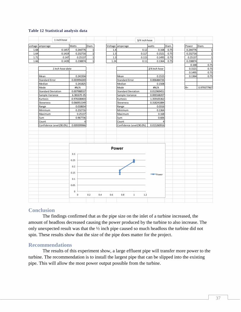
37
Table 12 Statistical analysis data
Conclusion The findings confirmed that as the pipe size on the inlet of a turbine increased, the
amount of headloss decreased causing the power produced by the turbine to also increase. The
only unexpected result was that the ½ inch pipe caused so much headloss the turbine did not
spin. These results show that the size of the pipe does matter for the project.
Recommendations The results of this experiment show, a large effluent pipe will transfer more power to the
turbine. The recommendation is to install the largest pipe that can be slipped into the existing
pipe. This will allow the most power output possible from the turbine.
voltage amperage Watts Diam. Voltage amperage watts Diam. Power Diam.
1.68 0.1457 0.244776 1 1.4 0.12 0.168 0.75 0.244776 1
1.64 0.1419 0.232716 1 1.3 0.117 0.1521 0.75 0.232716 1
1.71 0.147 0.25137 1 1.3 0.115 0.1495 0.75 0.25137 1
1.66 0.1439 0.238874 1 1.24 0.11 0.1364 0.75 0.238874 1
0.168 0.75
1 inch hose data 3/4 inch hose 0.1521 0.75
0.1495 0.75
Mean 0.241934 Mean 0.1515 0.1364 0.75
Standard Error 0.003994269 Standard Error 0.006484726
Median 0.241825 Median 0.1508
Mode #N/A Mode #N/A R= 0.979377967
Standard Deviation 0.007988537 Standard Deviation 0.012969451
Sample Variance 6.38167E-05 Sample Variance 0.000168207
Kurtosis -0.976508403 Kurtosis 1.359105362
Skewness 0.066951549 Skewness 0.318241884
Range 0.018654 Range 0.0316
Minimum 0.232716 Minimum 0.1364
Maximum 0.25137 Maximum 0.168
Sum 0.967736 Sum 0.606
Count 4 Count 4
Confidence Level(90.0%) 0.009399966 Confidence Level(90.0%) 0.015260916
1 inch hose 3/4 inch hose
0
0.05
0.1
0.15
0.2
0.25
0.3
0 0.2 0.4 0.6 0.8 1 1.2
Power
Power
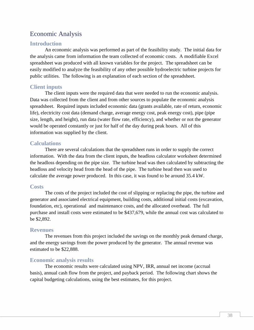
38
Economic Analysis
Introduction An economic analysis was performed as part of the feasibility study. The initial data for
the analysis came from information the team collected of economic costs. A modifiable Excel
spreadsheet was produced with all known variables for the project. The spreadsheet can be
easily modified to analyze the feasibility of any other possible hydroelectric turbine projects for
public utilities. The following is an explanation of each section of the spreadsheet.
Client inputs The client inputs were the required data that were needed to run the economic analysis.
Data was collected from the client and from other sources to populate the economic analysis
spreadsheet. Required inputs included economic data (grants available, rate of return, economic
life), electricity cost data (demand charge, average energy cost, peak energy cost), pipe (pipe
size, length, and height), run data (water flow rate, efficiency), and whether or not the generator
would be operated constantly or just for half of the day during peak hours. All of this
information was supplied by the client.
Calculations There are several calculations that the spreadsheet runs in order to supply the correct
information. With the data from the client inputs, the headloss calculator worksheet determined
the headloss depending on the pipe size. The turbine head was then calculated by subtracting the
headloss and velocity head from the head of the pipe. The turbine head then was used to
calculate the average power produced. In this case, it was found to be around 35.4 kW.
Costs The costs of the project included the cost of slipping or replacing the pipe, the turbine and
generator and associated electrical equipment, building costs, additional initial costs (excavation,
foundation, etc), operational and maintenance costs, and the allocated overhead. The full
purchase and install costs were estimated to be $437,679, while the annual cost was calculated to
be $2,892.
Revenues The revenues from this project included the savings on the monthly peak demand charge,
and the energy savings from the power produced by the generator. The annual revenue was
estimated to be $22,888.
Economic analysis results The economic results were calculated using NPV, IRR, annual net income (accrual
basis), annual cash flow from the project, and payback period. The following chart shows the
capital budgeting calculations, using the best estimates, for this project.

39
Table 13 Economic analysis results showing a positive income, but a negative NPV
-$114,576 NPV
2% IRR
$5,739 annual net income from project (accrual basis)
$19,995 annual cash flow from project
22 payback period (years)
Conclusion The NPV is negative, but this project may be worth pursuing. Qualitative factors such as
energy conservation, environmental, political, and public perception should be considered in
addition to the quantitative results found.
References This document contains information related to the economic analysis of the GRPUC
hydroelectric turbine project and the spread sheet that that information was calculated with. To
view the economic analysis spreadsheet contact IRE or Jeffrey Lange at
Physical Model The team created two physical models for the project. One was created for the
experiment to look at headloss and how it would affect the power output with different pipe
sizes. In order to be a scale model of the project, the model needed to have a head of six inches
and a ¼ inch diameter pipe that ran 12 feet long. The team decided that this would not work for
the experiment, and used a larger head and pipe. Pictures of the model used in the experiment
can be found in the experiment section of the report. The team then decided to create a
computerized model using Autodesk Inventor. This model was able to show the pipe and the
manholes along it.
Figure 26 A three dimensional layout of the pipe system with manholes
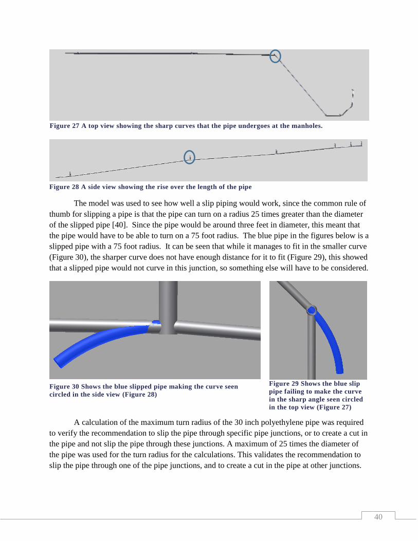
40
The model was used to see how well a slip piping would work, since the common rule of
thumb for slipping a pipe is that the pipe can turn on a radius 25 times greater than the diameter
of the slipped pipe [40]. Since the pipe would be around three feet in diameter, this meant that
the pipe would have to be able to turn on a 75 foot radius. The blue pipe in the figures below is a
slipped pipe with a 75 foot radius. It can be seen that while it manages to fit in the smaller curve
(Figure 30), the sharper curve does not have enough distance for it to fit (Figure 29), this showed
that a slipped pipe would not curve in this junction, so something else will have to be considered.
A calculation of the maximum turn radius of the 30 inch polyethylene pipe was required
to verify the recommendation to slip the pipe through specific pipe junctions, or to create a cut in
the pipe and not slip the pipe through these junctions. A maximum of 25 times the diameter of
the pipe was used for the turn radius for the calculations. This validates the recommendation to
slip the pipe through one of the pipe junctions, and to create a cut in the pipe at other junctions.
Figure 29 Shows the blue slip
pipe failing to make the curve
in the sharp angle seen circled
in the top view (Figure 27)
Figure 30 Shows the blue slipped pipe making the curve seen
circled in the side view (Figure 28)
Figure 28 A side view showing the rise over the length of the pipe
Figure 27 A top view showing the sharp curves that the pipe undergoes at the manholes.

41
Math model The mathematical model was used to determine if a pipe with a reduced area could still
be used to transport the effluent water from the wastewater treatment plant to the river, with a
high enough flow rate to justify putting a turbine in the line.
Assumptions The assumptions that were made were: that the daily flow rate would be seven million gallons
per day, the dynamic viscosity of water is 1.002 centipoise, the relative roughness of
polyethylene pipe is .0015 mm, and the velocity of the water in the ponds is zero using the big
tank assumption.
Description of how the math model was developed and executed The math model was developed to determine if a smaller pipe could handle the increased
flow and how much power could be generated by the turbine. The power calculations were done
in Microsoft Excel. The calculations for the increased flow were also done by hand.
Equations and Calculations
The equation used for the power calculation was the energy equation. The equation for
power produced by a turbine was also used.
Using the spreadsheet, the headloss calculations could be calculated quickly for any pipe. See
Appendix C to view pictures of the spreadsheet used.
The spreadsheet used equations such as, the Colebrook equation, the headloss equation,
the relative roughness equation, and the equation for Reynolds number.
The equations used to verify that the smaller pipe could handle the increased flow were
the full flow free outfall equation on page number 21-28/29 of the Core Engineering Concepts
book [41]. The graph for the coefficient of discharge was used to find the coefficient using the
Reynolds number. These equations were used to determine what the flow rate could be if there
was not a turbine in the effluent line to restrict the flow; and there was no governing system at
the pond, allowing them to drain as fast as possible.
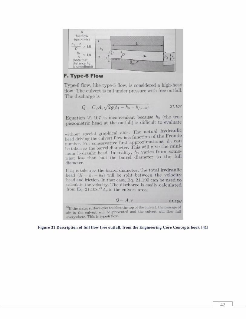
42
Figure 31 Description of full flow free outfall, from the Engineering Core Concepts book [41]
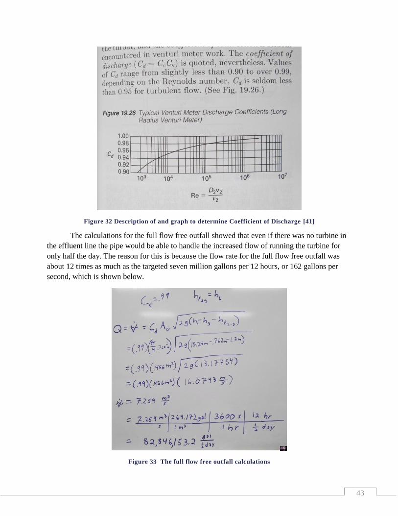
43
Figure 32 Description of and graph to determine Coefficient of Discharge [41]
The calculations for the full flow free outfall showed that even if there was no turbine in
the effluent line the pipe would be able to handle the increased flow of running the turbine for
only half the day. The reason for this is because the flow rate for the full flow free outfall was
about 12 times as much as the targeted seven million gallons per 12 hours, or 162 gallons per
second, which is shown below.
Figure 33 The full flow free outfall calculations
44
Evaluation Process Using the calculations from the full flow free outfall equations with a 30 inch pipe
running for half a day there could be about 82.8 million gallons that could be discharged. If it
was run the full day the pipe could discharge about 171.7 million gallons. Both of these values
are well above the required outflow of the seven million gallons that the wastewater treatment
plant must discharge daily. This means there is no doubt that the smaller pipe will be able to
discharge the amount of required water even with the added restriction of the turbine; and from
the headloss calculations there will still be enough head left in the water to generate power with
the turbine.
Future Steps The future steps to be taken for this are to verify the size of the turbine to be
recommended using the headloss spreadsheet for the amount of head that will be available to the
turbine. The amount of power the turbine produces can be used as the amount of electrical
energy that this project will be saving the GRPUC, and thus the amount of money that will be
saved as a result of the installation of the turbine can be calculated.
Validation and verification There are two major areas which require validation and verification for this project, the
power output of the physical apparatus and the economic analysis. The team looked at both of
these aspects, and both will also be looked at by professionals for approval.
Team Validation and Verification – Physical Apparatus The project contains two major aspects to the physical apparatus: the effluent pipe and
the powerhouse equipment. The pipe to be used for the project is a 30 inch polyethylene pipe
which will be slipped inside of the existing pipe. A fluids analysis was produced by the team
using headloss equations. These were placed in a Microsoft Excel spreadsheet which allowed the
team to change variables such as flow rate, pipe size, pressure head, and coefficient of friction.
By performing this analysis the team verified the estimated total power output of the system.
They were also able to validate recommendations to the client to operate the turbine only during
peak electrical load periods which produced the greatest amount of income for the client.
Fluid headloss through pipes were verified by the team through an experiment. Different
sized pipes were used in a hydro turbine generation model to measure varying power outputs of
the system. By using smaller pipes, the team showed that less power was produced due to greater
headloss through the system. This validates the team’s recommendation to use a 30 inch pipe in
the project at the wastewater treatment plant.
The team received a quote from a hydro turbine generator manufacturer. This company
gave a recommendation for a micro turbine which was sized for a specific amount of power
output based upon information they received from the team. The team then verified this power
45
output information by independently verifying this information through calculations. This
validates the recommendation for the size of the turbine generator recommended to the client.
A free flow water analysis was calculated to ensure the flow rate of water used in
calculations for power is valid. This calculation produced the maximum amount of water which
could flow through the pipe with no limitations to the inlet water flow. A flow rate of
approximately 82 million gallons can flow through the pipe in a 12 hour period with a constant
head of 50 feet. This is much greater than the required seven million gallons of water per 12 hour
period used for the model.
Team Validation and Verification – Economic Analysis The team researched all economic impacts for this project and how they will affect the
feasibility study. A financial spreadsheet was produced with all aspects of the project built into
it. Each separate component of the spreadsheet was changeable by the user and described how
each individual component affects the project of the whole. The end result of the spreadsheet
verified that the project would produce positive income over the lifetime of the project for the
client. This was used to validate if the project is economically feasible to go forward with, or if
the project is not worth pursuing by GRPUC.
Professional Validation and Verification – Physical Apparatus The physical apparatus requires validation and verification of power output as calculated
per the mathematical model. The power output was based upon available water flow, headloss of
the system, turbine efficiency, and generator efficiency. These will be validated and verified by
professional engineers and by manufacturers of the turbine generator.
Professional Validation and Verification – Economic Analysis The team’s economic model of the system requires validation and verification to ensure
the project will successfully meet its financial goals. An examination by GRPUC’s management
team as well as their financial team will be performed prior to moving forward with the project.
Additionally, an examination of the team’s plan to sell electrical power will be inspected by MP
and GRPUC’s financial team.
Reliability A major factor in the feasibility of this project depends on a long lasting system. The
system contains two major sub systems which are relatively independent when projecting their
sustainability: the powerhouse equipment package and the piping.
Powerhouse Equipment Package The powerhouse equipment package includes a variable flow turbine, induction
generator, gear drive, drive couplings, switchgear and controls panels, turbine inlet valve,
hydraulic power unit, and structural steel mounting frames. This package contains two limiting
components. The turbine runner has a minimum lifespan of 25 years, and the turbine bearings are
rated for a 100,000 hour lifespan or approximately 11 years of continuous use. A monthly
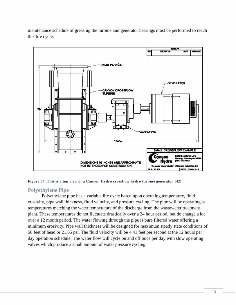
46
maintenance schedule of greasing the turbine and generator bearings must be performed to reach
this life cycle.
Figure 34 This is a top view of a Canyon Hydro crossflow hydro turbine generator [42].
Polyethylene Pipe Polyethylene pipe has a variable life cycle based upon operating temperature, fluid
erosivity, pipe wall thickness, fluid velocity, and pressure cycling. The pipe will be operating at
temperatures matching the water temperature of the discharge from the wastewater treatment
plant. These temperatures do not fluctuate drastically over a 24 hour period, but do change a lot
over a 12 month period. The water flowing through the pipe is pure filtered water offering a
minimum erosivity. Pipe wall thickness will be designed for maximum steady state conditions of
50 feet of head or 21.65 psi. The fluid velocity will be 4.41 feet per second at the 12 hours per
day operation schedule. The water flow will cycle on and off once per day with slow operating
valves which produce a small amount of water pressure cycling.
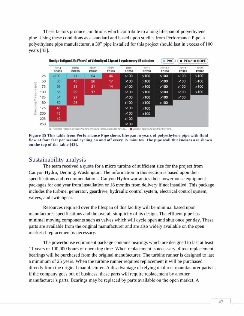
47
These factors produce conditions which contribute to a long lifespan of polyethylene
pipe. Using these conditions as a standard and based upon studies from Performance Pipe, a
polyethylene pipe manufacturer, a 30” pipe installed for this project should last in excess of 100
years [43].
ure 36
Sustainability analysis The team received a quote for a micro turbine of sufficient size for the project from
Canyon Hydro, Deming, Washington. The information in this section is based upon their
specifications and recommendations. Canyon Hydro warranties their powerhouse equipment
packages for one year from installation or 18 months from delivery if not installed. This package
includes the turbine, generator, geardrive, hydraulic control system, electrical control system,
valves, and switchgear.
Resources required over the lifespan of this facility will be minimal based upon
manufactures specifications and the overall simplicity of its design. The effluent pipe has
minimal moving components such as valves which will cycle open and shut once per day. These
parts are available from the original manufacturer and are also widely available on the open
market if replacement is necessary.
The powerhouse equipment package contains bearings which are designed to last at least
11 years or 100,000 hours of operating time. When replacement is necessary, direct replacement
bearings will be purchased from the original manufacturer. The turbine runner is designed to last
a minimum of 25 years. When the turbine runner requires replacement it will be purchased
directly from the original manufacturer. A disadvantage of relying on direct manufacturer parts is
if the company goes out of business, these parts will require replacement by another
manufacturer’s parts. Bearings may be replaced by parts available on the open market. A
Figure 35 This table from Performance Pipe shows lifespan in years of polyethylene pipe with fluid
flow at four feet per second cycling on and off every 15 minutes. The pipe wall thicknesses a re shown
on the top of the table [43].

48
replacement runner may be more difficult to locate since these are a more specialized part. A
runner may be retrofitted for the turbine, or one may be machined by a specialty shop if required.
Generators and switchgear will be replaced if needed from the original manufacturer.
Upon unavailability of these original replacement parts it will be very easy to replace these parts
with other manufacturer’s equipment. Electrical equipment including generators, switchgear, and
transformers are widely available from many manufacturers on the open market.
The success of the project directly relies on the effluent flow of the wastewater treatment
plant. The majority of this flow is received from Blandin Paper Company which is used in their
processes. If this flow is cut off for some reason such as the paper company shutting down, the
effluent flow of the pipe would be reduced to below one million gallons per day from seven
million gallons per day. This will directly affect the power output of the hydroelectric plant, and
would make the plant uneconomical to operate. This possibility is impossible for the team to
predict, but should be considered by the GRPUC if deciding to go forward with the project.
Contextualization
Multi-disciplinary aspects of the project Many disciplines need to be involved with the construction and implementation of the
hydro turbine generator project. All of the disciplines in this report have special attributes that
contribute to the feasibility and functionality of the project.
Mechanical engineers/Structural engineers
Mechanical and structural engineers will have many inputs into this project. The piping,
turbine, valves, and the building will all be designed by these engineers. The expertise that is
needed to size the pipes and the turbine for the correct amount of flow will be the responsibility
of the mechanical engineer. The way the building is designed for size and safety will be decided
by the structural engineer.
Electrical engineers
The electrical engineers will be responsible for getting the energy from the turbine to the
electrical system, for this project. This will include deciding the best generator to use, the
switchgear that will be needed, and the circuit breakers that are right for the system. They will
also design the electronics to operate the system, including water flowage control and sampling
systems that need to be implemented because of wastewater regulations.
Environmental engineers
Environmental engineers will be needed to look into the regulations and implementation
of the amount of water being discharged into the river. They will also be responsible for any
work done on the land by the river and how the project will affect the natural drainage of the
area. The environmental engineer will also need to make sure that the project is following the
regulations regarding the amount of undesirable chemicals being put into the river.
49
Administration
GRPUC administration will have to look at the financial aspects of the project and decide
if it is something they want to take to the board of directors for approval. This will include the
financial manager, the general manager, and the wastewater treatment manager.
Project Manager
The project manager will have to oversee the project if it is to be built. This will include
managing the project from start to finish and making sure it is being built to the specs in a timely
manner. This position will be looking out for GRPUC’s best interest and making sure the project
is kept to budget.
Contractors/builders
The contractors and builders that are hired for the job will need to have the tools and the
knowledge to follow the plans the engineers have designed. It is very important that the builders
can do the job safely and make the building aesthetically pleasing. They must also have the
proper equipment to do the job.
Hydro dam operators
The hydro dam operators will need to have the knowledge of how the system works and
how to control the water flowage and the amount of electricity that is being produced. The
operators will also have to know how to maintain the system within specifications.
Wastewater treatment plant operators
The wastewater treatment operators will be required to have knowledge of how the
system will work. To maintain the proper treatment of the wastewater, the operators need to have
input on the flowage through the treatment system.
Contextual aspects of the project Health
The health of the people who will have to operate the system and do maintenance on it is
a big concern for the project. Proper ventilation will have to be installed into the building, to
allow for fresh air to be exchanged as needed. The operators will also need to make sure that the
treated water has time to complete its process before entering the river. If too many chemicals
enter the river it could affect people that use the river for recreation.
Safety
Safety will be a big concern for this project. The people who will operate and maintain
the system will need to be sure that all safety procedures are followed. If safety measures are
violated or missing the situation must get resolved as soon as possible. In the design of the
system, all regulations need to be followed to meet safety standards. This will include hand
railings, grounding systems, guards, and locks to keep people away from equipment that could
injure them. Safety measures will have to be put into place to protect the workers and bystanders
during construction. This will require signage and fencing around deep openings and
construction areas.
50
Environment
This project will have to take into consideration the environmental impact the project will
have on the land and river surrounding the project. The big concern will be what is being put into
the river. Special run off blockades will have to be installed during construction to help reduce
any top soil erosion that could end up in the river. Another concern is that the wastewater that is
being discharged into the river has to maintain its cleanliness and be as chemical free as possible.
A final environmental concern is how the fish in the river will be affected by the change in the
flowage of the water. A positive environmental impact that should come from this project is that
energy is being captured from a source that is not putting any emissions into the air.
Global
On a global scale this project will not have a big effect. This project will reduce some
carbon emissions and make the world a little cleaner. It may also show that this system can be a
feasible way to capture energy that would otherwise go to waste. This could lead to similar
implementations around the world.
Society
This project will not affect society as a whole, but it could have an impact on local
residents. It could have economical and image impacts. By installing the system, it could reduce
the cost of electricity for GRPUC which in turn could reduce utility bills for the residents of
Grand Rapids. The image GRPUC would be showing is that they care about the environment and
that they are always looking for ways to implement green energy. This would make the
customers of that utility feel good the about the commission.
Ethical, Moral, and Legal
The main concern about the ethics of this project is how much money should be spent if
the project is not feasible but is good for the environment. This question is one that GRPUC may
have to decide for the people who are their customers.
Economic and Manufacturing This project could have economic benefits for the community of Grand Rapids. As
mentioned above, if the hydro turbine saves the utility money, that money could be passed on to
the residents. It also could add jobs to the community. This may be done with the addition of
operators or in the form of the construction workers who would be needed to build the project. It
would also create jobs where the pipes, turbine, and other parts are made.
Engineering, Creativity, & Ingenuity The engineering creativity, for this project, is to find a way to capture the potential
energy that is resting in the ponds, at the wastewater treatment facility. If the team can find a way
to do this feasibly, it could be implemented in many places around the world. The biggest
obstacle to overcome in this project is the amount of head loss in the piping system and the
efficiencies of the turbine generator system.
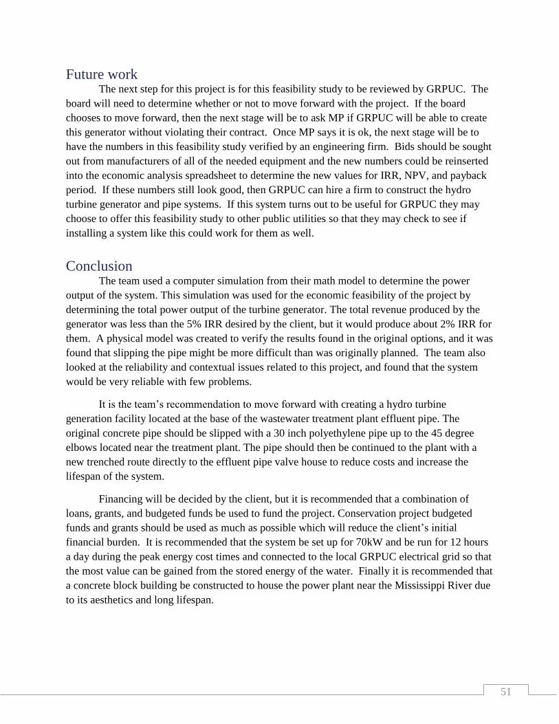
51
Future work The next step for this project is for this feasibility study to be reviewed by GRPUC. The
board will need to determine whether or not to move forward with the project. If the board
chooses to move forward, then the next stage will be to ask MP if GRPUC will be able to create
this generator without violating their contract. Once MP says it is ok, the next stage will be to
have the numbers in this feasibility study verified by an engineering firm. Bids should be sought
out from manufacturers of all of the needed equipment and the new numbers could be reinserted
into the economic analysis spreadsheet to determine the new values for IRR, NPV, and payback
period. If these numbers still look good, then GRPUC can hire a firm to construct the hydro
turbine generator and pipe systems. If this system turns out to be useful for GRPUC they may
choose to offer this feasibility study to other public utilities so that they may check to see if
installing a system like this could work for them as well.
Conclusion The team used a computer simulation from their math model to determine the power
output of the system. This simulation was used for the economic feasibility of the project by
determining the total power output of the turbine generator. The total revenue produced by the
generator was less than the 5% IRR desired by the client, but it would produce about 2% IRR for
them. A physical model was created to verify the results found in the original options, and it was
found that slipping the pipe might be more difficult than was originally planned. The team also
looked at the reliability and contextual issues related to this project, and found that the system
would be very reliable with few problems.
It is the team’s recommendation to move forward with creating a hydro turbine
generation facility located at the base of the wastewater treatment plant effluent pipe. The
original concrete pipe should be slipped with a 30 inch polyethylene pipe up to the 45 degree
elbows located near the treatment plant. The pipe should then be continued to the plant with a
new trenched route directly to the effluent pipe valve house to reduce costs and increase the
lifespan of the system.
Financing will be decided by the client, but it is recommended that a combination of
loans, grants, and budgeted funds be used to fund the project. Conservation project budgeted
funds and grants should be used as much as possible which will reduce the client’s initial
financial burden. It is recommended that the system be set up for 70kW and be run for 12 hours
a day during the peak energy cost times and connected to the local GRPUC electrical grid so that
the most value can be gained from the stored energy of the water. Finally it is recommended that
a concrete block building be constructed to house the power plant near the Mississippi River due
to its aesthetics and long lifespan.

52
Bibliography
[
1]
"Operating Hydropower Sites in Minnesota," [Online]. Available:
http://www.dnr.state.mn.us/waters/surfacewater_section/stream_hydro/hydropower_sites.ht
ml. [Accessed October 2012].
[
2]
"Hydro Plant Operator," [Online]. Available: http://www.mymajors.com/education-
requirements/Hydro-Plant-Operator. [Accessed October 2012].
[
3]
"Hydroelectric-Station Operator," [Online]. Available: http://dot-job-
descriptions.careerplanner.com/HYDROELECTRIC-STATION-OPERATOR.cfm.
[Accessed October 2012].
[
4]
"How Hydropower Plants Work," [Online]. Available:
http://science.howstuffworks.com/environmental/energy/hydropower-plant1.htm. [Accessed
October 2012].
[
5]
"Hydroelectric power: How it Works," [Online]. Available:
http://ga.water.usgs.gov/edu/hyhowworks.html. [Accessed October 2012].
[
6]
"Water Tubine," [Online]. Available: http://en.wikipedia.org/wiki/Water_turbine.
[Accessed October 2012].
[
7]
[Online]. Available: http://otherpower.com/otherpower_hydro.html. [Accessed
October 2012].
[
8]
ASTM by Committee, ASTM A746-09 Standard Specification for Ductile Iron
Gravity Sewer Pipe, ASTM, 2009.
[
9]
L. B. M. Brown, Chemistry the Central Science 11E, Upper Saddle River, NJ:
Pearson Education, Inc., 2009.
[
10]
[Online]. Available: http://hydro.org/. [Accessed October 2012].
[
11]
[Online]. Available: http://www.venezuelatuya.com/guayana/gurieng.htm. [Accessed
October 2012].
[
12]
"Power Generation," PALL, [Online]. Available:
http://japanese.pall.com/pdf/PGHYDEN.pdf. [Accessed October 2012].
[ "Butterfly Valves," Vaphydro, [Online]. Available:
53
13] http://www.vaphydro.bg/butterfly.valves.php. [Accessed October 2012].
[
14]
"Concrete Price Considerations- Cost of Concrete," [Online]. Available:
http://www.concretenetwork.com/concrete-prices.html. [Accessed October 2012].
[
15]
"Cost to Install a Concrete Block," [Online]. Available:
http://www.homewyse.com/services/cost_to_install_concrete_block_wall.html. [Accessed
October 2012].
[
16]
"Build a Storage Shed Cost," [Online]. Available: http://www.fixr.com/costs/build-
storage-shed. [Accessed October 2012].
[
17]
"Cost for 20x40 Garage," Armstong Steel, [Online]. Available:
http://www.armstrongsteelbuildings.com/steel-buildings-faqs/need-20x40-garage-cost.php.
[Accessed October 2012].
[
18]
NERC, "The Energy Fix," 02 12 2011. [Online]. Available: www.theenergyfix.com.
[Accessed 08 10 2012].
[
19]
National Fire Protection Association, NFPA 70: National Electrical Code, NFPA,
2010.
[
20]
IEC, IEC Standard.
[
21]
"High Voltage Circuit Breaker About," Engineering Edge, Solutions By Design,
[Online]. Available:
http://www.engineersedge.com/instrumentation/components/high_voltage_circuit_breaker.ht
m. [Accessed October 2012].
[
22]
"The ABB Group - Automation and Power Technologies," ABB, [Online]. Available:
www.abb.com. [Accessed October 2012].
[
23]
"Transformer," [Online]. Available: http://hyperphysics.phy-
astr.gsu.edu/hbase/magnetic/transf.html. [Accessed October 2012].
[
24]
"Hydroelectric Power Generation," [Online]. Available:
http://users.owt.com/chubbard/gcdam/html/hydro.html. [Accessed October 2012].
[
25]
"Application Note: Introduction to Current Transformers," Elkor, [Online].
Available: http://www.elkor.net/pdfs/AN0305-Current_Transformers.pdf. [Accessed
October 2012].

54
[
26]
National Fire Protection Association, NFPA 70: National Electrical Code, NFPA,
2010.
[
27]
"National Enviornmental Policy Act," NEPA, [Online]. Available:
http://ceq.hss.doe.gov/. [Accessed October 2012].
[
28]
"Minesota Department of Natural Resources," MNDNR, [Online]. Available:
http://www.dnr.state.mn.us/index.html. [Accessed October 2012].
[
29]
M. D. o. N. Resources, Shoreland Management Rules, Chapter 6120.
[
30]
M. P. C. Agency, Stormwater Best Management Practices Manual, Saint Paul, MN:
Minnesota Pollution Control Agency, 2000.
[
31]
C. D. Department, Interviewee, [Interview]. October 2012.
[
32]
Kevin, Interviewee, Personal interview with: Kevin (LASTNAME) at Minnesota
Power on 10/14/2012. [Interview]. 14 October 2012.
[
33]
"Minnesota — Incentives/Policies for Renewables & Efficiency," DSIRE, [Online].
Available:
http://dsireusa.org/incentives/index.cfm?re=0&ee=0&spv=0&st=0&srp=1&state=MN.
[Accessed October 2012].
[
34]
"Options for Grants and Loans," Minnesota Department of Commerce, [Online].
Available: http://mn.gov/commerce/energy/topics/financial/Grants-Loans.jsp. [Accessed
October 2012].
[
35]
"Minnesota Power - Power Grant Program," DSIRE, [Online]. Available:
http://dsireusa.org/incentives/incentive.cfm?Incentive_Code=MN22F&re=0&ee=0.
[Accessed October 2012].
[
36]
"Renewable Development Fund (RDF)," DSIRE, [Online]. Available:
http://dsireusa.org/incentives/incentive.cfm?Incentive_Code=MN09R&re=0&ee=0.
[Accessed October 2012].
[
37]
"Overrview," Xcel Energy, [Online]. Available:
http://www.xcelenergy.com/Environment/Renewable_Energy/Renewable_Energy_Grants/R
enewable_Development_Fund?stateSelected=true. [Accessed October 2012].

55
[
38]
"Federal - Incentives/Policies for Renewables & Efficiency," DSIRE, [Online].
Available:
http://dsireusa.org/incentives/incentive.cfm?Incentive_Code=US53F&re=0&ee=0.
[Accessed October 2012].
[
39]
Client, Interviewee, [Interview]. 2012.
[
40]
[Online]. Available:
http://uuc1.poly.edu/ProfessionalTrainingProgram/Trenchless%20Technologies%20Manual.
pdf.
[
41]
P. Michael R. Lindeburg, Core Engineering Concepts for Students and Professionals,
Belmont, California: Professional Publications, Inc., 2010.
[
42]
Canyon Hydro, Small Crossflow Example Elevation, Deming, WA: Canyon Hydro,
2012.
[
43]
Performance Pipe, "Performance Pipe," 2012. [Online]. Available:
http://www.performancepipe.com/en-us/Documents/PP402%20Fatigue.PDF?Redirect=1.
[Accessed 23 11 2012].
[
44]
"List of NFPA Codes & Standards," NFPA, [Online]. Available:
http://www.nfpa.org/AboutTheCodes/List_of_codes_and_Standards.asp. [Accessed October
2012].

i
Appendix A
List of acronyms used
GRPUC – Grand Rapids Public Utilities Commission
IRE – Iron Range Engineering
IRR – Internal rate of return
NPV – Net present value
MP – Minnesota Power
NEC – National Electric Code
HVAC – Heating, ventilation, and air conditioning
PVC – Polyvinyl chloride
HDPE – High density polyethylene
LDPE – Low density polyethylene

ii
Appendix B
Creation of the turbine used in the experiment

iii
A turbine was needed for the GRPUC hydro turbine generator groups experiment. The
team looked to purchase an inexpensive turbine online but could not find any. The team then
looked to see if any pumps could be used backwards to act as a turbine. Most pumps were found
to not work well enough, but one option was found that could output a little energy. This option
was very inefficient and the team decided to pursue creating their own.
The team decided to construct a turbine using cut 2D sheets to construct into a whole.
The sheets were cut by IRE’s Hurricane laser CNC laser cutter (Figure 37).
The parts that were created included: a 10 bladed impellor (Figure 39), the inside walls
(Figure 40), and the outside walls, one with an outlet (Figure 41), one without (Figure 38). All
of the parts were fashioned with holes to allow for easy manufacturing. The Impellor had a
302mm hole in the center which was 6mm smaller than the diameter of the shaft that would fit
Figure 37 Hurricane Laser CNC laser cutter
Figure 39 Impeller Figure 40 Inside wall Figure 41 Outside with
outlet
Figure 38 Outside wall
without outlet

iv
through it. This caused a tight press fit and allows the impellor to spin the shaft. The outside
walls also required a press fit with the bearings that were used.
The pieces were then assembled and saved in a .idw Inventor drawing which was then
convertible into the .dxf format that was needed to run on the CNC laser cutter (Figure 42).
Figure 42 Assembled pieces ready to be cut by the laser printer
The Hurricane laser machine uses inputs from a .dxf file created by Autodesk Inventor.
From the file it creates a cutting path. The laser then needs to be set to run at specific speeds and
intensities. There are specific given values to run the machine at for different materials. Once
the speed and the intensity are set, the laser is ready to cut the parts.
The laser cuts the inside path of all of the lines it is given. That means that it cuts exactly
the distance on the inside cuts, or holes, but it cuts on the inside of the outer lines, that means the
outside cuts will be off by the width of the laser. Since this is small, and this part did not require
close tolerances, this was mentioned, but ignored while building the parts in Inventor.
The pieces were first cut out of wood (Figure 44,Figure 43), since the wood is cheaper
and easier to cut, it makes for a good practice cut to see how effective the parts will be.
Figure 44 Outer wall and inner wall cut from wood Figure 43 Broken wooden impeller

v
The walls looked good (Figure 44), but the impeller was breaking (Figure 43), this lead to
the second impeller design being thicker.
The second design was good but a few improvements were needed. First off the sharp
edges on the outside were creating leftover material to hang from the edges after it was cut on the
machine. The second problem was that the sharp edges on near the center were allowing the
impeller to crack if handled roughly (Figure 45). Finally the inner diameter of the whole was
expanded so that it would not crack when press fit onto the shaft. Fixing these problems lead to
the third, and final, design of the impeller (Figure 47).
Figure 46 Second design of the impeller cut from
plastic
Figure 45 Second design of the impellor breaking
on the inside
Figure 47 Final design of the impeller cut from plastic

vi
Figure 48 Failed drill hole and the top is a failed
jig saw cut
In order for water to flow into the impeller there needed to be a hole in the side of the
walls. A few ways to complete this were to drill a hole in the material after it was screwed
together, another option was to cut a hole in the sides and create a square piece to put into the
hole. The team experimented with these options and found that while you can drill a hole going
into the material, it was not practical to try to drill one in the side (Figure 49); and cutting the
material with a jig saw left the material scared but actually still together (Figure 48). It was
finally decided to cut out a new set of side walls that had the hole already missing (Figure 40)
and find a way to get a square piece to connect to the inlet hose.
The pieces were cut out of a large sheet of plastic (Figure 50) and the remainder of the
plastic was kept for other projects.
Figure 49 Failed drill hole into the sidewall
Figure 50 Large sheet of plastic with the designed pieces cut
from it
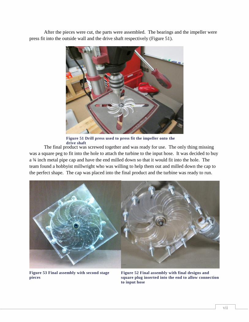
vii
Figure 51 Drill press used to press fit the impeller onto the
drive shaft
After the pieces were cut, the parts were assembled. The bearings and the impeller were
press fit into the outside wall and the drive shaft respectively (Figure 51).
The final product was screwed together and was ready for use. The only thing missing
was a square peg to fit into the hole to attach the turbine to the input hose. It was decided to buy
a ¾ inch metal pipe cap and have the end milled down so that it would fit into the hole. The
team found a hobbyist millwright who was willing to help them out and milled down the cap to
the perfect shape. The cap was placed into the final product and the turbine was ready to run.
Figure 53 Final assembly with second stage
pieces
Figure 52 Final assembly with final designs and
square plug inserted into the end to allow connection
to input hose
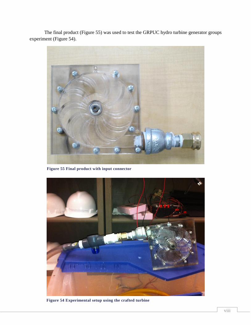
viii
The final product (Figure 55) was used to test the GRPUC hydro turbine generator groups
experiment (Figure 54).
Figure 55 Final product with input connector
Figure 54 Experimental setup using the crafted turbine

ix
Appendix C
Pictures of the economic analysis
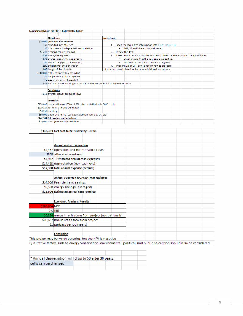
x
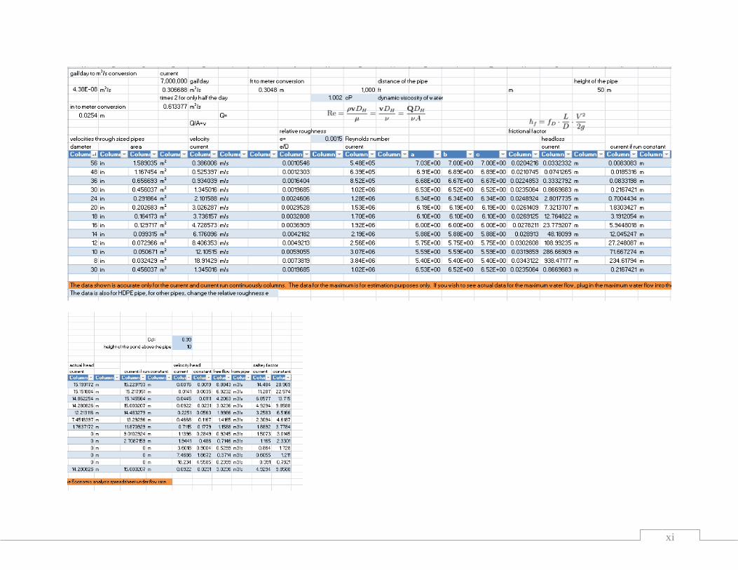
xi
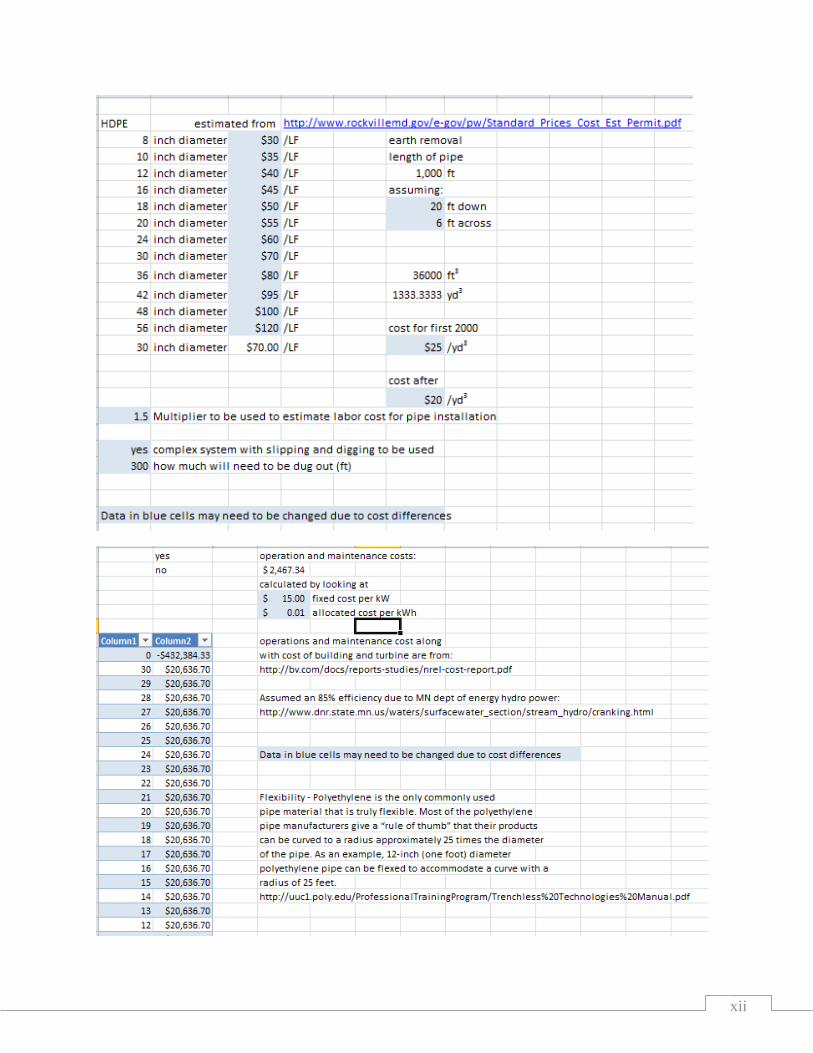
xii

xiii
Appendix D
Pictures of the GRPUC site
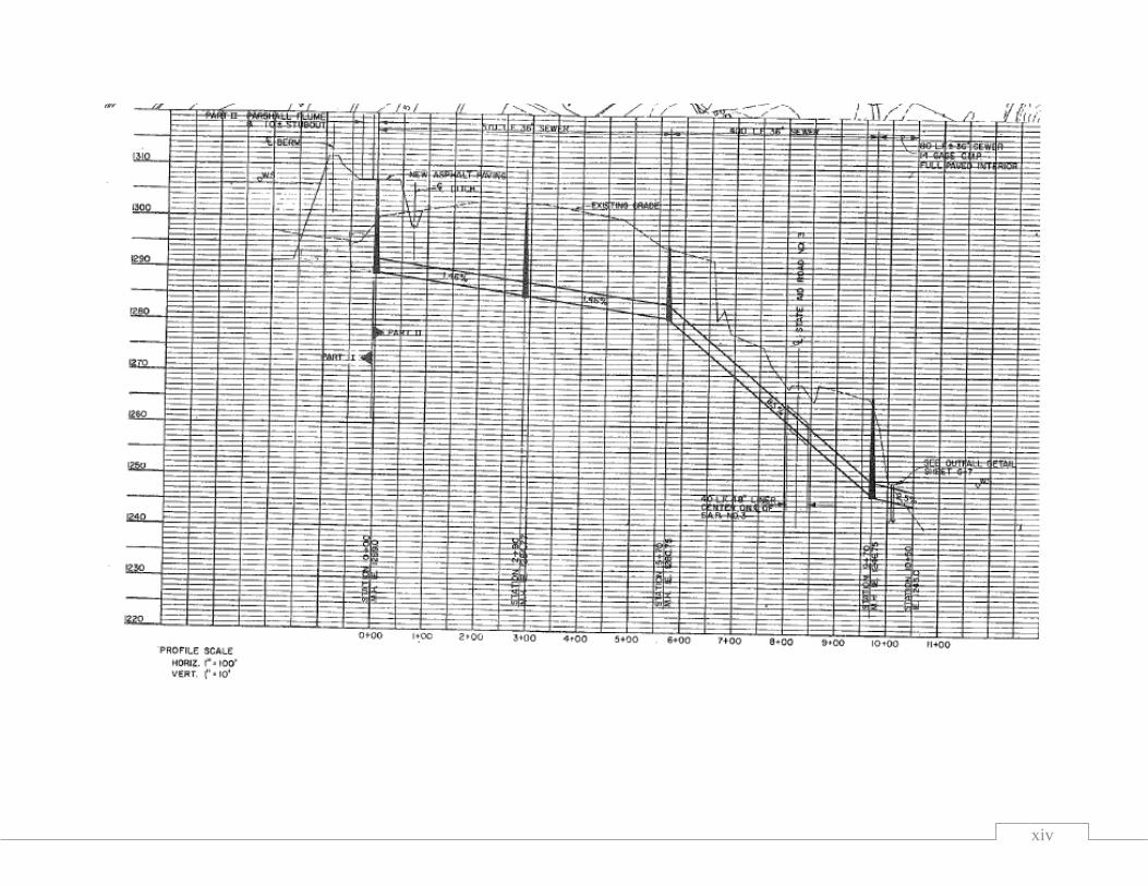
xiv
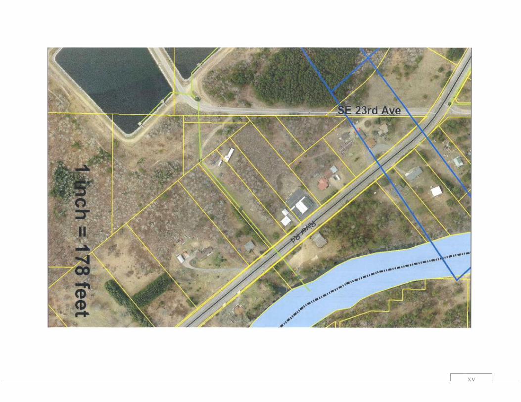
xv