GRADESHIFT UDL INSTRUCTION MANUAL - csl … · GradeShift UDL Instruction Manual 1. Quick ......
13
GRADESHIFT UDL INSTRUCTION MANUAL 1. QUICK GUIDE
Transcript of GRADESHIFT UDL INSTRUCTION MANUAL - csl … · GradeShift UDL Instruction Manual 1. Quick ......

GRADESHIFT UDL INSTRUCTION MANUAL
1. QUICK GUIDE
GradeShift UDL Instruction Manual
1. Quick Guide
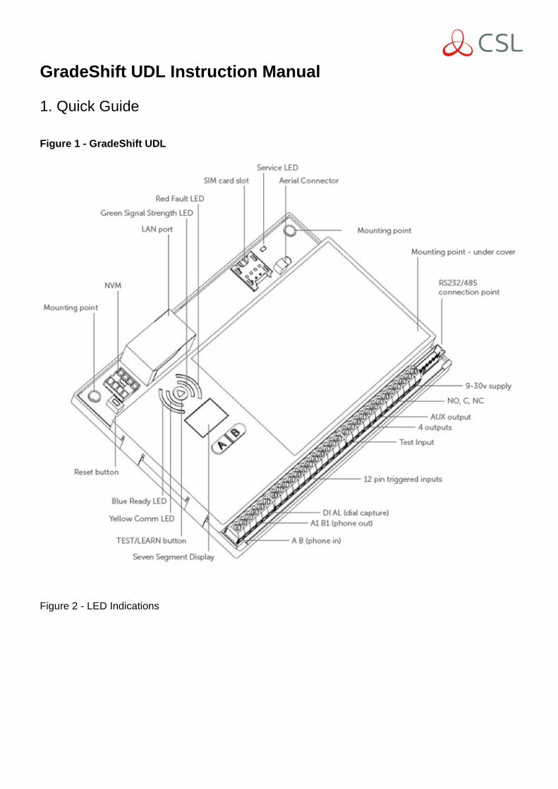
Figure 1 - GradeShift UDL
Figure 2 - LED Indications
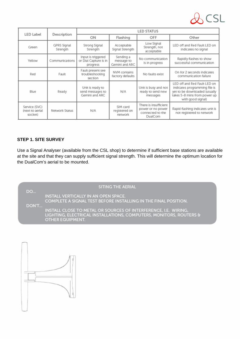
STEP 1. SITE SURVEY
Use a Signal Analyser (available from the CSL shop) to determine if sufficient base stations are availableat the site and that they can supply sufficient signal strength. This will determine the optimum location forthe DualCom’s aerial to be mounted.

STEP 2. INSTALLATION
a. Ensure the aerial is mounted and connected in the correct position to achieve maximum signalstrength. Apply power and wait for 5-8 minutes for the unit to connect to the network and download itsprogramming file. Once completed the Green Signal Strength LED should be on or flashing, indicatingan acceptable signal, the Red Fault LED should be off and the Blue Ready LED will be on. A percentagewill also be shown on the SSD (Seven Segment Display) which should be 40% or higher. Now theGradeShift can be located into a suitable enclosure for the grade of installation.
b. Wire the input triggers, attach the RS232/485 cable or connect the Control Panel’s Digi-Modem PSTNterminals to the GradeShift’s Dial Capture terminals (refer to wiring diagrams in Section 2 of thisdocument). For a dual path device remember to connect for PSTN or LAN.
c. Connect the fault output terminals to the Control Panel as required (refer to wiring diagrams in Section2 of this document).
d. Power down the the Power Supply Unit (PSU), connect 9-30volts DC supply to the GradeShift’s powerterminals and repower the PSU. Note that any voltage below 12v will indicate a low battery warning.
e: For installations using Dial Capture no GradeShift configuration is required. Simply check that yourDigi-Modem has an ARC telephone number (ie 01) and an account number (ie 1234), select yoursignalling format, connect the GradeShift and test.
f. For pin triggering installations, ensure that the panel is in its normal state then press and hold theTest/Learn button for 3 seconds until the Green Signal Strength LED and the Yellow CommunicationsLED flash alternately. Please note it is recommended that this step is not carried out until the instructionsabove has been completed.
STEP 3. TEST & SELF LEARN USING THE BUTTON
To send test signals, tap the Test/Learn button (less than 1 second). The 7 SSD should change to c1,c2, c3, A. (A = the Gemini Platform acknowledges the alarm signal). Simultaneously, the YellowCommunications LED indicates comms progress. If available, GradeShift will test the secondary (wired)path using C1, C2, C3, A to indicate successful communication.
If the test is not successful the Red Fault LED will light for 2-3 seconds at the end of the sequence. TheGradeShift will make multiple call attempts if unsuccessful.
To self-learn the inputs, push the Test/Learn button for 3-5 seconds. ‘Pi’ will be displayed during the self-learn process.
STEP 4. CHECK SIGNALS HAVE BEEN RECEIVED AT YOUR ARC
Once you have successfully tested your GradeShift, make sure that you check with your ARC to see thatthey are receiving signals. This can be achieved by calling your ARC or using their web based secureplatform.

INSTRUCTION MANUAL
1. ADVANCED INSTRUCTIONS
1.1 LINE FAULT
Ensure you wire the fault output in accordance with the standard you wish to adhere to. For furtherinformation on the different options please follow the wiring diagrams in Section 2 and the full InstallationManual available via the Installer Zone on the CSL website: www.csldual.com/installer-zone
1.2 ENABLE/DISABLE PSTN/LAN
To enable/disable PSTN use the following A & B button sequence:
To enable/disable LAN:
INCREASE PSTN/RADIO FAIL (for 10 mins – engineer mode):
1.3 FAIL TO COMMUNICATE MONITORING USING DIAL CAPTURE
If you want to monitor the Dial Capture connection, connect an output configured as PSTN line fault onyour Control Panel to one of the GradeShift’s inputs. Designate that input as Dial Capture fail at your

ARC. For wiring instructions see Section 2.
RS232/485: for installations using RS232 or RS485 simply follow the wiring diagrams in Section 2.
LAN: For installations using LAN as a communication path connect a Cat5 (or higher).
2. WIRING DIAGRAMS
2.1 PIN TRIGGERING
In the operation, GradeShift is triggered by applying or removing zero volts to the input terminals 1-12.No external pull-up resistors will be required. This is generally achieved via the digital communicatoroutputs of an intruder alarm or similar Control Panel. GradeShift will signal alarm conditions and willgenerate the relevant messages and forward them via Gemini to the ARC. Installers are advised that theintended use should avoid situations where the rate of triggering exceeds therate at which messages may be sent to, or received by, the ARC receiver.
2.2 DIAL CAPTURE

In this operation, GradeShift simulates and replaces the phone line connection to the Control Panel’sDigi-Modem.
The Control Panel’s Digi-Modem must use one of the following alarm formats: Fast Format, Contact IDor SIA. In the event theControl Panel needs to send a signal to the ARC, GradeShift will capture the message and forward it, viaGemini, to the ARC. The Digi-Modem must have an ARC telephone number (ie 01) and account number(ie 1234) programmed for Dial Capture towork.
If you want to monitor the Dial Capture connection, you will need to connect an output configured asPSTN line fault on your Control Panel to one of the GradeShift’s inputs. That input then needs to bedesignated as Dial Capture Fail at your ARC.
2.3 PSTN
2.4 RS232/485

For further instructions on Control Panel programming please review the how to guides on the InstallerZone of our website: www.csldual.com/installer-zone
3. TROUBLE SHOOTING
Q. The Red Fault LED is continuously flashing, what does this mean?
A. This happens when the unit is first powered and needs to download its configuration file from theGemini Platform which can take 5-8 minutes. You must ensure that the Yellow Service (SVC) LED isflashing every 3-5 seconds, which indicates that the unit is connected to the mobile network.
Q. The GradeShift repeats the ‘power-up’ sequence but never completes it.
A. The power supply has a low output voltage or is unable to supply the current required by theGradeShift when it is activated. Check the power supply with a multimeter. Also, test the GradeShift’soperation when powered by a ‘known good’ 12 volt battery.
Q. The Red Fault LED is on, what is the problem?
A. Please refer to the error code on the SSD and the error code list at the end of this document.
Q. Triggering via ‘Dial Capture’ does not seem to work.
A. During communication between the Control Panel and the GradeShift, the display should show ‘DC’. If‘DC’ is displayed, but c1, c2, c3, A is not, the panel may not be compatible or is configured to send aprotocol that GradeShift does not recognise. If available, check the Control Panel’s programming andselect an alternate signalling format. Please check our online compatibility table for the latest list ofcompatible Control Panels and formats: www.csldual.com.

Q. The ARC is not receiving messages.
A. In most cases the GradeShift will explain the reason a signal cannot be sent to your ARC using anerror code shown on the SSD. If, after trying to rectify the displayed fault, the GradeShift can still nottransmit to your ARC please contact CSL Technical Support.
4. ERROR CODES
In the event of an issue the GradeShift will display an error code on the SSD. This is the letter ‘E’followed by a number. A list of error codes is shown on pages 10 and 11 along with the potentialsolution. During operation, an Error Code may be displayed for up to 4 minutes. During this time, if thefault is corrected, or another error of higher priority occurs then the display will indicate the new value.

Critical Errors:To alert the User and Installer to critical error conditions, after the normal sounder beeps have timed outthe GradeShift unit will continue to beep once every 5 minutes.
5. SUPPORT
For assistance please telephone or email our CSL Technical Support. Before doing so please review theInstallation Manual and How To Guides on the Installer Zone of our website:www.csldual.com/installer-zone
UK Tel: +44 (0)1895 474 444Ireland Tel: 1800 855 695Netherlands Tel: 010 - 714 54 93

Email: [email protected]: 08.30 to 18.00 weekdays, 10.00 to 16.00 Saturday (all times GMT)
6. OPTIONAL EXTRAS
All the products below are available to order via your ARC or the CSL Installer Shop.
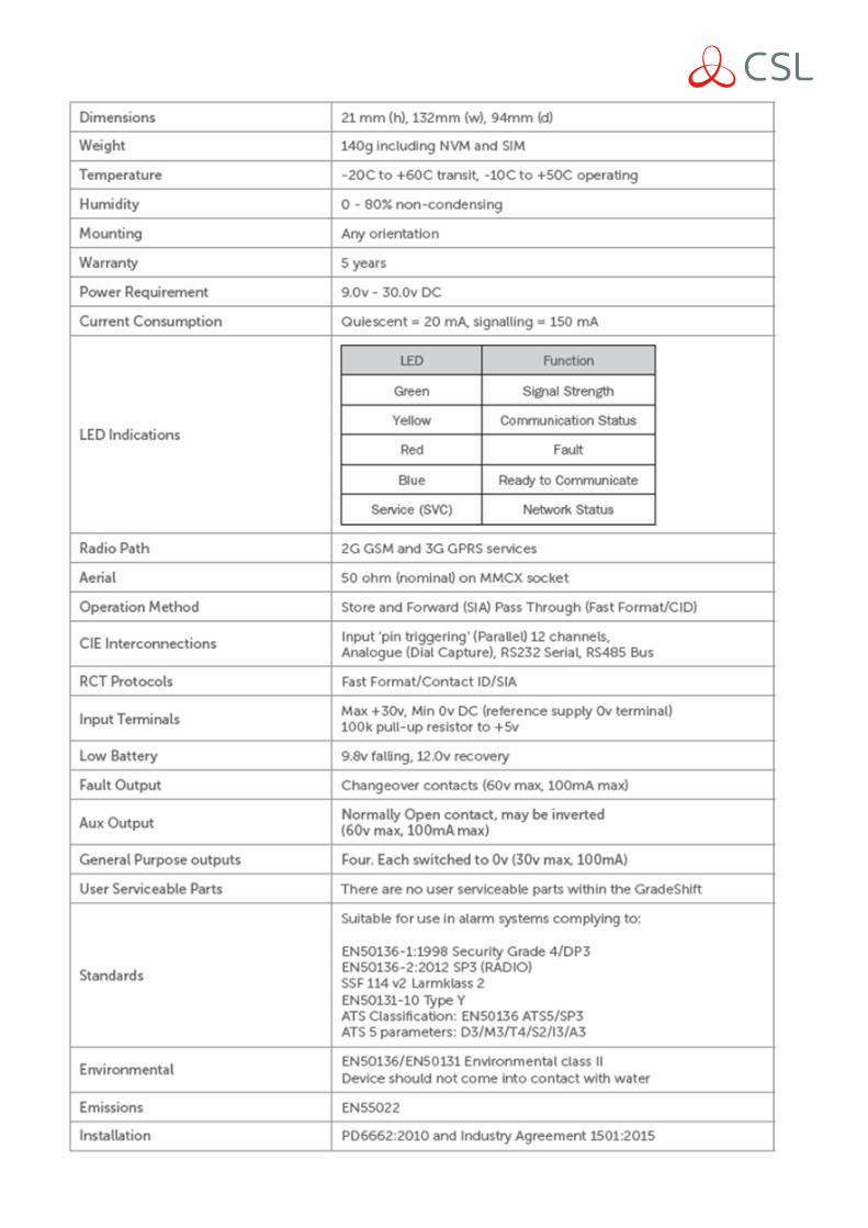
SPECIFICATIONS