GR-326: StRenGtheninG the weakeSt link in modeRn day ...€¦ · 4 GR-326: StRenGtheninG the...
15
% White Paper APRIL 2013 GR-326: STRENGTHENING THE WEAKEST LINK IN MODERN DAY ULTRAFAST OPTICAL NETWORKS AUTHORS: Sean Grenon Zach Forman Joe Wong Ky Ly Tom Mamiya Bernard Lee Revision 2
Transcript of GR-326: StRenGtheninG the weakeSt link in modeRn day ...€¦ · 4 GR-326: StRenGtheninG the...

1 GR-326: StRenGtheninG the weakeSt link in modeRn day ultRafaSt optical netwoRkS
%
white paper apRil 2013
GR-326: StRenGtheninG the weakeSt link in modeRn day ultRafaSt optical netwoRkS
authoRS:
Sean Grenon Zach forman Joe wong ky ly tom mamiya Bernard lee
Revision 2
2 GR-326: StRenGtheninG the weakeSt link in modeRn day ultRafaSt optical netwoRkS
AmericasUSA EAST 1-888-32-SENKOUSA WEST 1-858-623-3300TEXAS [email protected]
AsiaHONG KONG +852-2121-0516SHANGHAI +86-21-5830-4513SHENZHEN [email protected]
EuropeUK +44 (0) 118 982 1600ITALY +39 011 839 98 28POLAND +48 71 776 [email protected]
Asia PacificAUSTRALIA +61 (0) 3 [email protected]
Middle East North AfricaDUBAI +971 4 [email protected]
JapanTOKYO +81 (0) 3 [email protected]

3 GR-326: StRenGtheninG the weakeSt link in modeRn day ultRafaSt optical netwoRkS
Contents 4
5
6
7
11
12
13
13
Executive Summary
Introduction to GR-326: How it all began?
How is a jumper assembly made?
-Preparation of fiber cable,Termination,
-Polishing
Why is GR-326 CORE important and what
does the testing involve?
-Service Life Test
-Extended Service Life Test
Connector Defects: Case Studies
Summary
References
Biography
GR-326: StRenGtheninG the weakeSt link in modeRn day ultRafaSt optical netwoRkS

4 GR-326: StRenGtheninG the weakeSt link in modeRn day ultRafaSt optical netwoRkS
figure 1 increase in Global demand for fiber optic connectors
executive Summary
In 2012, leading market and technology analysts announced their
finding which concluded that in 2016, the worldwide consumption
volume of connectors and mechanical splices will increase by a factor
of 2, reaching over 1.57billion units as compared to the number of
703 million in 2011. The American region led in global market share
with 54% in 2011. American consumption is forecast to expand to at
an average annual growth rate of 10.8% during the forecast period.
The Asia Pacific (APAC) region is forecasted to show the fastest
growth with an average annual growth rate of 25 percent (2011-
2016). EMEA (Europe, Middle East and Africa) fiber optic connector
volume consumption, with 19.5 percent relative market share, trailed
the second-place APAC (Asia Pacific) region in 2011. The forecasted
trend is shown in Figure 1.
As demand for optical connectors increases globally, so does
the supply. When one visits trade shows, one will find numerous
suppliers offering from basic components to finished cable assembly
products. One key fact that end users have discovered in recent
years is ‘not all connectors are equal’. The quality, reliability, and
performance of optical components and cable assembly products
such as patch cords are assured by selecting the best components
and by terminating and polishing with the best equipment and
procedures. These components and procedures must assure that the
jumper assemblies meet or exceed the requirements of all pertinent
industry specifications such as the internationally recognized GR-326
standards. This paper describes the relevance of the criteria in the
applicable industry specifications, as well as the importance of the
physical parameters and how they relate to the performance of the
jumper assembly.
1600
1400
1200
1000
800
600
400
200
0
americas 380 421 468 519 576 640
apac 186 233 291 364 455 569
emea 137 93 125 169 231 365
17%annually
Growingmillions $
2011 2012 2013 2014 2015 2016
Source: ligthwave magazine, July 2012
26% americas25% apac11% emea
Growing annually
5 GR-326: StRenGtheninG the weakeSt link in modeRn day ultRafaSt optical netwoRkS
introduction to GR-326: how it all began?
GR-326-CORE (Generic Requirements for Singlemode Optical
Connectors and Jumper assemblies) was initially created by Bellcore
and continues to evolve as one of the more popular standards in
the telecommunications industry. Bell Communications Research,
Inc. or Bellcore was established in the early 1980’s by the Regional
Bell Operating Companies (RBOC’S) upon their separation from
AT&T. Bellcore served as the research and development, training
and standard setting arm for the RBOC’s. Following a divestiture
of the company in 1996, Bellcore was officially renamed Telcordia
Technologies in 1999. In 2012 Telcordia was acquired by Ericsson.
GR-326-CORE was written as part of Telcordia’s General Requirement
series to be consistent with the Telecommunications Act of 1996
and it is intended to be the industrial specifications for long
haul high-speed applications such as telecommunications and
cable TV. There has been a total of four issues of GR-326, initial
release, Issue 2 December 1996, Issue 3 September 1999 and
the current Issue 4 February 2010. The Telcordia views in any
particular release are developed from the expressed needs of
the Telcordia Technical Forum (TTF), the TTF is made up from the
companies who participated in the development of each new issue.
As networks evolve and new products are offered the standards
are typically reviewed to see if there are changes that need to be
made or criteria added. A good example of this was the addition
of four wavelength testing (1310nm, 1490nm, 1550nm, 1625nm)
in GR-326 issue 4, this was added because of the heavy use of
connectors and cable assemblies in FTTH networks. Field data is also
a very important part of the process when determining the need
for reissues of the standard. As some of the current networks have
been in service for many years, review of FIT (failure in time) rates
along with post mortem investigations provide invaluable data
about the components long term reliability. When the standards
are developed, there are many other industry standards that are
referenced. Standards from IEC, TIA/EIA, ASTM, ISO, ITU, UL as well as
other Telcordia General Requirement standards are referenced for
test procedures, test criteria, intermatebility criteria etc. When these
standards are updated, they need to be reviewed to determine if a GR-
326 reissue is needed to bring them in line. The purpose for GR-326 is
to determine a connector or connector assembly’s ability to perform
in various operating conditions, and to determine long term reliability.
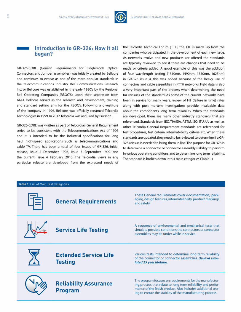
The standard is broken down into 4 main categories (Table 1)
table 1: list of main test categories
General RequirementsThese General requirements cover documentation, pack-aging, design features, intermateability, product markings and safety
Service life testingA sequence of environmental and mechanical tests that simulate possible conditions the connectors or connector assemblies may be under while in service
extended Service life testing
Various tests intended to determine long term reliability of the connector or connector assemblies. Usuava simu-lated 25 year lifetime.
Reliability assurance program
The program focuses on requirements for the manufactur-ing process that relate to long term reliability and perfor-mance of the finish product. Also includes additional test-ing to ensure the stability of the manufacturing process

6 GR-326: StRenGtheninG the weakeSt link in modeRn day ultRafaSt optical netwoRkS
how is a jumper assembly made?
So what should be taken into consideration when choosing a ‘good’
product? What are the features that one should look for that defines
the quality of any connector or jumper assembly? In order to appreci-
ate the significance of a standard compliant product, one must first
understand the process of actually making an optical connector as-
sembly and the potential problems that could occur at each of the
stages.
There are three main processes in the termination of a jumper, Prepa-
ration, Termination and Polishing (Figure 2) and a total of 15 steps
where negligence at any one of the steps will result in an inferior
jumper assembly. Each process consists of small steps, and each step
requires strict Quality Control of not only the equipment used, but
also how each step is carried out. So let us break these processes down
into their fundamental steps and see the potential quality issues. For
illustration purposes the process described here is the termination of
a connector on to a 3mm jacket cable with Kevlar reinforcement.
Fig
ure
2: C
on
nec
tor t
erm
inat
ion
pro
cess
an
d t
hei
r po
ten
tial
mis
take
s
preparationof fibre cable
terminationof fibre cable
polishingof connector endface
1. Stripping of outer cable jacket 1. inject epoxy and insert fiber 1. cleave fiber
2. trimming of kevlar fibers to length 2. crimp kevlar to back post 2. Remove excess epoxy by hand or machine
3. Stripping of 900um buffer 3. crimp outer jacket 3. polish endface
4. clean bare fiber 4. cure connector in oven
5. check fiber for damage
6. mix two part epoxy
7. degas epoxy
8. check ferule id
wrong procedures by line operator (e.g. trimmed kevlar length)
wrong procedures by line operator (e.g. curing stage)
wrong procedures by line operator (e.g. removal of epoxy)
poorly maintain or wrong use of tools poorly mainteined or wrong use of tools poorly maintain or wrong use of tools (e.g. cleaver)
low quality or inappropriate material (e.g: epoxy)
low quality or inappropriate material (e.g: epoxy)
low quality or inappropriate material (e.g: polishing films)
Pro
ced
ure
sP
ote
nti
al
Mis
take
s
preparation of fiber cable
1 Strip outer jacket - Using a suitable jacket stripper, the
outer jacket is removed without damaging the 900um buffered fiber
inside. The stripper blade must be sharp and the appropriate inner di-
ameter must be used so that it does not damage the 900um buffered
fiber inside. Even though the fiber is protected by a 900um buffer, if
this buffer is pinched or kinked, then there’s a high possibility of dam-
age to the fiber inside.
2 trimming of kevlar fibers to length - This may
not seem serious, but long, protruding Kevlar fibers are at best unsight-
ly, but at worst will hinder the correct fitting of the strain relief boot.
The result is insufficient mechanical support when a jumper assembly
of any significant length is left to dangle. Insufficient mechanical sup-
port in these circumstances will result in fiber stress and/or breakage.
3 Stripping of 900um buffer - At this stage, dam-
age to the fiber may not be visible to the naked eye or even
seem superficial, but will cause performance degradation or in
the worst case scenario cause complete loss of transmission. Never-
theless, through the Extended Humidity Test, any defects to the fiber
during stripping will be detected. The stripper used must be sharp
and its internal diameter (ID) tight enough to remove not only the
900um buffer, but also the acrylate coating around the fiber. However,
the ID cannot be so tight as to score or scratch the fiber. Close atten-
tion must also be paid to the length of buffer to be removed, especial-
ly in the case of tight buffered fiber. When using unheated strippers,
no more than 10mm of buffer should be removed at any one time.
Attempting to remove more will result in over bending, causing micro
and macro bending induced stress on the fiber. Such damage at this
stage will result in poor performance, but in the worst case will cause
fiber breakage during the epoxy curing process later on.
4 clean bare fiber to ensure acrylate coating has been
removed. When this thin coating of acrylate isn’t completely removed
it is impossible to insert the fiber into the ferrule. Trying to do so will
invariably result in fiber breakage and a wasted connector.

7 GR-326: StRenGtheninG the weakeSt link in modeRn day ultRafaSt optical netwoRkS
5 check for fiber damage - A four direction fiber bend
check should be performed to check for fiber damage or breakage
during the buffer removal process. If the fiber was scored or cracked
it will break. It’s important to check fiber damage at this stage before
insertion into the ferrule to minimize fiber breakage during the curing
process.
6 mix the two part epoxy - Two-part epoxies such
as Epo-Tek 353ND are commonly used to bind the fiber inside the
ferrule. Some manufacturers have taken steps to lower their cost by
the use of glue or standard epoxy from hardware stores instead of
the proper epoxy compound which will result in premature failure of
the connectors (usually within months). Hence why one must always
avoid such inferior products. Poorly mixed epoxy will result in poor
adhesion and or lower glass transition operating temperatures and, as
a result, the fiber will piston, varying the fiber height in relation to the
ferrule surface. Excessive fiber protrusion will lead to fiber damage.
7 degas to ensure epoxy is free of air bubbles - Once mixed, the epoxy will have tiny air bubbles trapped inside it, and
removal of these air bubbles is essential. Air bubbles inside the epoxy
will expand under the temperatures it’s exposed to during curing; this
will result in stress on the fiber, or in the worst case fiber breakage. In
either case, IL performance will suffer.
8 check ferrule id is clear of any obstruction - An obvious but sometimes overlooked step. Anything inside the
ferrule that obstructs the insertion of a fiber will result in wasted
preparation time as mentioned is the steps above. Although not a
critical step, it will possibly highlight an issue with a vendor’s ferrule
or connector and help maintain productivity.
termination
1 inject epoxy & insert fiber - Whether this is
performed manually or automatically, care must be taken to not inject
too much epoxy. Failure to control the amount of epoxy injected
will cause an over flow of epoxy, which can result in blockage of the
curing oven connector receptacles, polishing fixture receptacles and,
of course, the seizing of connector mechanics. All of which are time
consuming and expensive to rectify. Care must always be taken to
avoid stubbing the fiber or to attempt to insert the fiber too quickly.
Doing may result in fiber breakage.
2 crimp kevlar to back post - Crimping must be
performed with a crimp tool set to the correct torque. The crimp die
must also be of the correct size and shape, usually round or hexagonal,
and must be in good condition. If the die size is too large or worn and
the torque set too low, the resulting crimp will not hold the Kevlar and
connector back post together securely enough to provide sufficient
tensile load protection. If however, the die is too small or torque set
too high, it’s possible the back post can be crushed, damaging the
fiber inside. Also, the Kevlar must be evenly place around the back
post. If the Kevlar is not placed around evenly, it will significantly
reduce the retention strength.
3 Crimp outer jacket - Same die size and shape concerns
as mention for Kevlar crimping, as well as the same concern regarding
the appropriate torque setting. Over crimping here will cause damage
to the fiber.
4 Cure connector in oven - Care must be taken when
placing the connector into the curing oven. Stubbing the fiber
protruding from the ferrule may cause the fiber to break. Even if the
fiber only partially breaks, it may potentially be cracked further down
the fiber. This essentially renders the termination useless and would
require re-termination with a fresh connector, wasting time and
resources.
polishing
1 cleave fiber - When cleaving, the cleave point should be
as close to the epoxy as possible, and performed with one clean cut.
Excessive force and any pushing action should be avoided to prevent
fiber cracking. Also the blade of the cleaver must be properly maintain
and sharp enough. Fibers should be periodically checked under a
microscope to ensure the cleaver blade is working properly.
2 Remove epoxy by hand or by machine - This
should be performed at low speed with low pressure to prevent
cracking the fiber.
3 polish using a suitable machine and proce-dure - Polishing isn’t just to make the ferrule end face nice and clean.
Polishing is the final and crucial part of jumper assembly termination.
Polishing defines the geometric parameters of the ferrule end face,
parameters that affect connectivity and performance. Critical param-
eters such as apex offset, fiber protrusion, end face radius and end
face quality are created and controlled through polishing.

8 GR-326: StRenGtheninG the weakeSt link in modeRn day ultRafaSt optical netwoRkS
figure 3 figure 4
cost benefit of using GR-326 coRe connectors?
Many have asked “what is the cost benefit of using a GR-326CORE
certified connector”. In comparison a GR-326CORE connector may be
double the price of a similar looking non GR-326-Core product. Thus
one must consider the network in totality and not just the cost of one
component itself. Also, one has to move away from the concept of
reducing the initial Capital Expenditure cost (CAPEX) to the concept
of reducing Total Cost of Ownership which takes into account the
potential maintenance costs in the near future. Hence, the authors
have made a model based on standard FTTH networks and cost
analysis provided by the FTTH Council Europe.
Based on a typical 1:32 PON network with 10 connectors from the OLT
to the ONT and assuming the cost per homes connect is US$1,000/
home, the difference in cost per Homes Connect is less than 1% of
the total homes connect cost when using a GR-326CORE certified
versus a non-GR-326CORE connector. 1% of US$1000 equals US$10/
home connect. Nevertheless, from a CAPEX point of view, the use of
the non-GR-326 connectors is still a saving although it is only US$10/
home (approximately the price of a large pizza).
Nonetheless, GR-326CORE does provides an assurance in reliability
unmatched by the other non-compliant connectors. An average cost
of replacing a faulty connector is approximately US$50/connector. If
a network operator takes into account that within the 20 years the
FTTH network’s lifetime, if a mere 2%, or 1 in 50 connectors fail, it will
already render the use of GR-326CORE connectors to be more cost
effective than using a non-compliant product. This saving does not
include losses in terms of:
• Revenue due to down time (e.g. Video on Demand, voice calls, etc)
• Penalty due to service disruption (Service Level Agreement penalty)
• Customer confidence
In Figure 3, we have compared a 20-year Total Cost of Ownership
between the uses of GR-326CORE versus non-GR-326CORE connectors.
The analysis clearly shows that although initial CAPEX is less for non-
GR326CORE case but in the span of 20 years, the average cost (repair
of faulty connectors and loss of revenue) will be 2x the cost of using
a GR-326CORE certified connector. The additional 1% per home pass
for using a GR-326CORE certified connector is definitely a worthwhile
assurance by any experienced network operator.
2
1,8
1,6
1,4
1,2
1
0,8
0,6
0,4
0,2
0
civil+labour
active material cost
passive material cost (excluding connector)
connector cost (GR certified)
connector cost (non-GR certified)
connector cost
Repair cost
potential loss of revenue
cost analysis ofGR-326coRe vs non-GR-326coRe connectors
total cost of ownership comparison between GR-326coRe vs non-GR-326coRe connectors
17%
5%
15% 16%
2% 1%
78%
GRcertified
non GRcertified
9 GR-326: StRenGtheninG the weakeSt link in modeRn day ultRafaSt optical netwoRkS
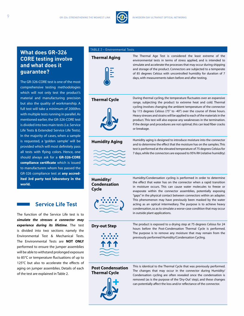
taBle 2 – environmental tests
Thermal Aging The Thermal Age Test is considered the least extreme of the
environmental tests in terms of stress applied, and is intended to
simulate and accelerate the processes that may occur during shipping
and storage of the product. Connectors are subjected to a temperate
of 85 degrees Celsius with uncontrolled humidity for duration of 7
days, with measurements taken before and after testing.
Thermal Cycle During thermal cycling, the temperature fluctuates over an expansive
range, subjecting the product to extreme heat and cold. Thermal
cycling involves changing the ambient temperature of the connector
by 115 degrees Celsius (75° to -40°) over the course of three hours.
Heavy stresses and strains will be applied to each of the materials in the
product. This test will also expose any weaknesses in the termination.
If the design and procedures are not optimal, this can lead fiber cracks
or breakage.
Humidity Aging Humidity aging is designed to introduce moisture into the connector
and to determine the effect that the moisture has on the samples. This
test is performed at the elevated temperature of 75 degrees Celsius for
7 days, while the connectors are exposed to 95% RH (relative humidity)
Humidity/ Condensation Cycle
Humidity/Condensation cycling is performed in order to determine
the effect that water has on the connector when a rapid transition
in moisture occurs. This can cause water molecules to freeze or
evaporate within the connector assemblies, potentially exposing
“gaps” in the physical contact between connectors within an adapter.
This phenomenon may have previously been masked by the water
acting as an optical intermediary. The purpose is to achieve heavy
condensation, so as to simulate a worse-case condition that may occur
in outside plant applications.
Dry-out Step The product is exposed to a drying step at 75 degrees Celsius for 24
hours before the Post-Condensation Thermal Cycle is performed.
The purpose is to remove any moisture that may remain from the
previously performed Humidity/Condensation Cycling.
Post Condensation Thermal Cycle
This is identical to the Thermal Cycle that was previously performed.
The changes that may occur in the connector during Humidity/
Condensation cycling are often revealed once the condensation is
removed (as is the purpose of the ‘Dry-Out’ step), and these changes
can potentially affect the loss and/or reflectance of the connector.
what does GR-326 coRe testing involve and what does it guarantee?
The GR-326-CORE test is one of the most
comprehensive testing methodologies
which will not only test the product’s
material and manufacturing precision
but also the quality of workmanship. A
full test will take a minimum of 2000hrs
with multiple tests running in parallel. As
mentioned earlier, the GR-326-CORE test
is divided into two main tests (i.e. Service
Life Tests & Extended Service Life Tests).
In the majority of cases, when a sample
is requested, a ‘golden sample’ will be
provided which will most definitely pass
all tests with flying colors. Hence, one
should always ask for a GR-326-CORE
compliance certificate which is issued
to manufacturers whom has passed the
GR-326 compliance test at any accred-
ited 3rd party test laboratory in the
world.
Service life test
The function of the Service Life test is to
simulate the stresses a connector may
experience during its lifetime. The test
is divided into two sections namely the
Environmental Test & Mechanical Tests.
The Environmental Tests are NOT ONLY
performed to ensure the jumper assemblies
will be able to withstand prolonged exposure
to 85°C or temperature fluctuations of up to
125°C but also to accelerate the effects of
aging on jumper assemblies. Details of each
of the test are explained in Table 2.
10 GR-326: StRenGtheninG the weakeSt link in modeRn day ultRafaSt optical netwoRkS
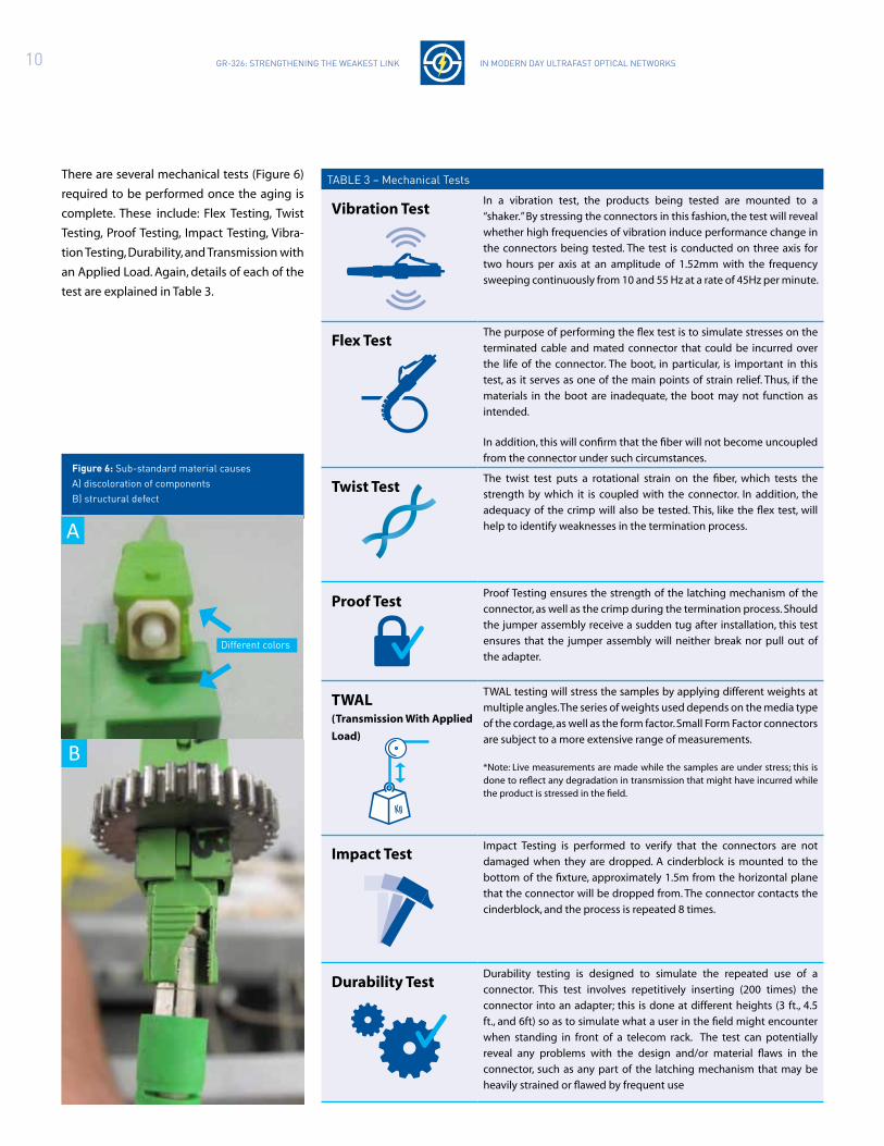
taBle 3 – mechanical tests
Vibration TestIn a vibration test, the products being tested are mounted to a
“shaker.” By stressing the connectors in this fashion, the test will reveal
whether high frequencies of vibration induce performance change in
the connectors being tested. The test is conducted on three axis for
two hours per axis at an amplitude of 1.52mm with the frequency
sweeping continuously from 10 and 55 Hz at a rate of 45Hz per minute.
Flex TestThe purpose of performing the flex test is to simulate stresses on the
terminated cable and mated connector that could be incurred over
the life of the connector. The boot, in particular, is important in this
test, as it serves as one of the main points of strain relief. Thus, if the
materials in the boot are inadequate, the boot may not function as
intended.
In addition, this will confirm that the fiber will not become uncoupled
from the connector under such circumstances.
Twist TestThe twist test puts a rotational strain on the fiber, which tests the
strength by which it is coupled with the connector. In addition, the
adequacy of the crimp will also be tested. This, like the flex test, will
help to identify weaknesses in the termination process.
Proof TestProof Testing ensures the strength of the latching mechanism of the
connector, as well as the crimp during the termination process. Should
the jumper assembly receive a sudden tug after installation, this test
ensures that the jumper assembly will neither break nor pull out of
the adapter.
TWAL (Transmission With Applied
Load)
TWAL testing will stress the samples by applying different weights at
multiple angles. The series of weights used depends on the media type
of the cordage, as well as the form factor. Small Form Factor connectors
are subject to a more extensive range of measurements.
*Note: Live measurements are made while the samples are under stress; this is done to reflect any degradation in transmission that might have incurred while the product is stressed in the field.
Impact TestImpact Testing is performed to verify that the connectors are not
damaged when they are dropped. A cinderblock is mounted to the
bottom of the fixture, approximately 1.5m from the horizontal plane
that the connector will be dropped from. The connector contacts the
cinderblock, and the process is repeated 8 times.
Durability TestDurability testing is designed to simulate the repeated use of a
connector. This test involves repetitively inserting (200 times) the
connector into an adapter; this is done at different heights (3 ft., 4.5
ft., and 6ft) so as to simulate what a user in the field might encounter
when standing in front of a telecom rack. The test can potentially
reveal any problems with the design and/or material flaws in the
connector, such as any part of the latching mechanism that may be
heavily strained or flawed by frequent use
figure 6: Sub-standard material causes a) discoloration of components B) structural defect
There are several mechanical tests (Figure 6)
required to be performed once the aging is
complete. These include: Flex Testing, Twist
Testing, Proof Testing, Impact Testing, Vibra-
tion Testing, Durability, and Transmission with
an Applied Load. Again, details of each of the
test are explained in Table 3.
B
A
different colors

11 GR-326: StRenGtheninG the weakeSt link in modeRn day ultRafaSt optical netwoRkS
extended Service life test
The criteria for connector and jumper assembly extended
service life testing are exclusive to GR-326-CORE. The testing
includes exposure to a variety of environments, including
additional Environmental Testing and Exposure Testing. The
additional Environmental Tests include extended versions of the
Thermal Life, Humidity, and Thermal Cycle. These tests, which run
for at least 2000 hours each (83 days), are further studies in the life
of the connector across a range of service environments. Testing
is non-sequential, so there is no cumulative effect. The Exposure
Tests include Dust, Salt Fog, Airborne Contaminants, Ground
Water Immersion, and Immersion/Corrosion.
During the extended Environmental Testing, many of the
extruded compounds used in jacketing and buffering will shrink
after exposure to elevated temperatures, which can cause micro
bending in the glass fibers and induce excessive loss.
dust can seriously impair optical performance.
Particles that contaminate endface can block
optical signals and induce loss. Whether or not the
dust particles find an exposed path to a ferrule
endface is largely a matter of probability. Over time, dust particles
will find their way to the optical connection if it is possible. While
the dust particles are not difficult to remove, the cleaning process
involves disconnecting the connector, which not only stops the
transmission, but also exposes the endface to additional risk of
contamination. This test involves intense exposure to a dust of
specified size particles in order to determine if there is a risk of
any particle finding its way to the ferrule endfaces.
Salt fog (referred to as Salt Spray) is performed
to guarantee the performance of the jumper
assembly in free breathing enclosures near the
ocean. This test involves exposing the connector to
a high concentration of Sodium Chloride (NaCl) over an extended
period. After the test, optical testing is performed, followed by a
visual inspection to confirm that there is no evidence of corrosion
on the materials.
The airborne contaminants test is
designed to guarantee the performance and
material stability of connectors in outdoor
applications with high concentrations of pollution.
The test repeatedly exposes mated and unmated connectors to
various gases and inspects the connector not only optically, but also
performing the same visual examination as in the Salt Fog test. An
assortment of volatile gases is used in a small chamber for 20 days to
simulate prolonged exposure to these elements.
The materials are also verified in the immersion/corrosion test. This test
has no optical requirements, but instead involves a
prolonged submersion in uncontaminated water. This
test, like Dust, Salt Fog, and Airborne Contaminants, involves both
mated and unmated connectors. Mated connectors are checked for
ferrule deformation by measuring the Radius of Curvature before
and after the test, and comparing the values. If the ferrule is not
geometrically stable during this test, it could be an indication of a
flaw in the zirconia material used in the ferrule. Unmated connectors
are checked for Fiber Dissolution, which involves checking to see
if the fiber core has not recessed too far into the fiber cladding.
The final exposure test is Groundwater immersion. This test verifies the ability of the
product to withstand underground applications.
The Immersion/Corrosion test is strictly to verify the
materials involved, and uses de-ionized or distilled water. Connectors
deployed in underground environments are much more likely
to be exposed to contaminated mediums if their enclosures fail.
During this test, the connector is exposed to a variety of chemicals
found in sewage treatment and agricultural fertilization, among
other applications, as well as biological mediums. These chemicals
include ammonia, detergent, chlorine, and fuel. Presence of these
chemicals can have a detrimental effect on the materials comprising
the connector and adapter, reducing optical performance.
In summary, the Key Product Features that we look at when
determining short and long term reliability are:
Materials: Plastics (Flammability rating of V1 or better in
accordance with UL94, Fungus rating of 0 per ASTM G21-
96), Metals, Metallic Plated Surfaces (Corrosion, Salt Spray),
Zirconia Grade (Extended Humidity Aging).
Termination Process: Cleanliness, Epoxy Type, Proper
Preparation and Application of Epoxy, Curing Time, Curing
Temperature, Correct Crimp Sizes and Pressure, Cable
Component Strip Lengths, Kevlar Placement, Polishing.
Intermatebility: Critical Dimensions in accordance with
applicable TIA/EIA FOCIS Standards.
1
2
3

12 GR-326: StRenGtheninG the weakeSt link in modeRn day ultRafaSt optical netwoRkS
connector defects: case Studies
The adoption of GR-326-CORE standard is an assurance of not only
the performance but also the reliability of the product. Nevertheless,
there are manufacturers all over the world whom are still not GR-326
compliant and have been selling their products in the market posing
as similar quality as those who have taken the effort to comply to the
standards. This section of the whitepaper would like to share some of
the case studies where non-compliant products have failed and has
affected the service providers’ network.
dimension defect
Connector dimensional non-compliance can result in engagement
and disengagement force issues, but just as seriously, they may not fit
into industry standard test equipment. Figure 5A shows an SC APC
connector unable to fit into a Data-Pixel interferometer chuck, due
to an inner housing that is wider than that specified by international
standards. Figure 5B shows a ferrule lodge into the adapter and
unable to be removed as the dimension of the adapter was too small.
Eventually, the ferrule broke off from the connector body.
material defect
Use of substandard materials can result in discoloration, distortion
and mechanical malfunction when put through environmental
testing. Discoloration as shown in Figure 6A is not of great concern,
but distortion and mechanical failure is as seen in Figure 6B. Figure
7 shows the worst case scenario of SC adapters melting during damp
heat testing. Note that in the same photograph, the GR-326 compliant
connectors attached to the adapter were not affected by the testing
and retained its integrity.
workmanship defect
Due to improper crimp ring placement during crimping, the upper
most FC connector in Figure 8 exhibited cable retention pull force
well below the requirements specified GR-326. More seriously shown
in Figure 9A & 9B, where there is a gap between the ferrule and the
flange during the termination process. If the gap is too big, that
place becomes an air pocket which will, during expansion at higher
temperature, exert pressure on the fiber thus causing the fiber to
break (Figure 9C). A sample of a good connector can be seen in Figure
9D.
B
B
DC
A
A
figure 5: non-compliant to standard dimension could cause a) fitting mismatch or even B) damage during operations
crimp ring too low
Buffer not fully inserted to back of ferrule
air bubble due to poor production process
acceptable connector that passed the testing
insufficient epoxy used in the process
crimp ring right position
figure 7: Sub-standard material unable to withstand environmental test
figure 9: Samples of connector terminations quality
figure 8: improper crimp ring placement during crimping
Broken off ferrulewrong dimension
non GR-326 compliant
GR-326 compliant
13 GR-326: StRenGtheninG the weakeSt link in modeRn day ultRafaSt optical netwoRkS
Summary
Jumper assembly reliability is guaranteed not only by using quality
components and manufacturing processes and equipment, but
also by adherence to a successful Quality Assurance program.
While jumper assemblies themselves are typically tested 100% for
insertion loss and return loss, there are many other factors that need
to be monitored to ensure the quality of the jumper assembly. One
of the most important factors is the epoxy. Epoxies typically have a
limited shelf life and working life, or “pot life.” Most epoxies used in
fiber optic terminations are two-part epoxies and, while they cure
at elevated temperatures, preliminary cross-linking will begin upon
mixing. Once this has started, the viscosity of the epoxy can begin to
change, making application more difficult over time. Mixing two-part
epoxies introduces trapped air, or “bubbles”, which is injected into
the connector. This trapped air introduces inconsistency in the cured
epoxy, leading to a high risk of mechanical failure. The trapped air, or
bubble count, must be minimized.
Many of the tools used in jumper assembly production also has
periodic maintenance and a limited tool life. This includes all
stripping, cleaving and crimping tools. Most stripping tools, whether
they are hand tools or automated machines, can be damaged by the
components of the cable, most notably the aramid yarn strength
members. When a cleaving tool wears out and a clean score is not
made, it is almost impossible to detect during manufacturing.
However, the result could be non-uniform fiber breakage during
cleaving, which can result in either breaking or cracking the fiber
below the ferrule endface.
In conclusion, the integrity of the incoming materials and
manufacturing processes, once specified, needs to adhere by all the
appropriate guidelines and procedures. The importance of these
materials not only has a strong influence on product reliability, but
also on product performance. GR-326 CORE is that assurance of
performance and reliability.
GR 326COMPLIANT
14 GR-326: StRenGtheninG the weakeSt link in modeRn day ultRafaSt optical netwoRkS
References
1. tia/eia-578-B.3, “commercial Building telecommunications cabling Standard”, telecommunications industry association, april 2000
2. telcordia GR-326-coRe, “Generic Requirements for Singlemode optical connectors and Jumper assemblies”, issue 4, telcordia technologies, february 2010
3. “patch cord Quality, Reliability and performance - the impact of industry Specifications and physical parameters on patch cord performance”, panduit corporation white paper, december 2003
4. “the cost of meeting europe’s network needs”, ftth council europe, July 2012
Biography
Zack forman joined Resolute technologies in June of 2012. Since then, he has been performing environmental and mechanical testing in accordance with GR-326, and has assisted in a number of projects since then. currently, he serves as a fiber optic lab technician under Sean Grenon.
ky is currently the Senior Staff engineer at Senko Shenzhen where he joined since 2007. prior to joining Senko, ky spent 3 years working as an engineer at hamamatsu photonics kk, as part of their intelligent Vision Systems research team. then, he was responsible for tests/experimentation and camera control software development. prior to hama-matsu photonics ky worked as an engineer at panasonic for 7 ½ years in their european mobile phone division based in the uk. Responsible for programming of automated Smt laser inspection machines and quality data feedback.
Sean Grenon joined Resolute technologies in november 2008 as the Regional lab manager. Resolute technologies is an independent test facility with a focus on passive optical components and specializing in GR-326 testing for fiber optic connectors and cable assemblies. Sean has been involved in many telcordia technical forums (ttf) for various stan-dards and is a member of the Verizon foc program. prior to joining Resolute Sean was the Verizon foc program and lab manager for curtis Strauss from 2007 to 2008. Before joining curtis Straus, from 2000 to 2007 Sean held various positions at fiber optic network Solutions. Sean worked in manufacturing engineering, Research and development before starting the Reliability and ftth design Verification programs for fonS.
tomoyuki (tom) mamiya joined Senko Japan in July 1999, and then joined Senko advanced components in the united States from Japan to manage all global engineering efforts as an engineering manager in february 2000. tom worked in various engineering and product development positions before being promoted to Global Vice president of engineer-ing in 2006. tom went back to Senko Japan in 2010 to be responsible for all engineering activities in Japan.prior to joining Senko, tom had worked for fiber optic component and equipment manufacturing company in Japan for more than 5 years as R&d engineer. tom held over 10 patents in fiber optic component field in world-widely, in the uS, europe, Japan, and taiwan.
dr. Bernard lee joined Senko advanced components (australia) pty ltd in 2011 as the R&d director. prior to joining Senko, Bernard was working at telekom malaysia (tm) R&d from 2003 till 2009. in 2010, Bernard was transferred to telekom malaysia’s (tm) head office as the assistant General manager for the Group Business Strategy where he oversees the company’s business direction on fixed and wireless broadband and applications. Bernard has published various technical papers, including international journals, conference papers and also white papers on high-speed communications systems and networks especially on ip based communications and high speed communications semiconductor devices. currently, Bernard holds the Vice president position of the asia pacific ftth council.

15 GR-326: StRenGtheninG the weakeSt link in modeRn day ultRafaSt optical netwoRkS
%