GPU real time hatching - WSCG
9
GPU real time hatching Suarez Jordane Université Paris 8 2 rue de la liberté 93526, Saint Denis, France [email protected] Belhadj Farès Université Paris 8 2 rue de la liberté 93526, Saint Denis, France [email protected] Boyer Vincent Université Paris 8 2 rue de la liberté 93526, Saint Denis, France [email protected] ABSTRACT Hatching is a shading technique in which tone is represented by a series of strokes or lines. Drawing using this technique should follow three criteria: the lighting, the object geometry and its material. These criteria respectively provide tone, geometric motif orientation and geometric motif style. We present a GPU real time approach of hatching strokes over arbitrary surfaces. Our method is based on a coherent and consistent model texture mapping and takes into account these three criteria. The triangle adjacency primitive is used to provide a coherent stylization over the model. Our model computes hatching parameter per fragment according to the light direction and the geometry and generates hatching rendering taking into account these parameters and a lighting model. Dedicated textures can easily be created off-line to depict material properties for any kind of object. As our GPU model is designed to deal with texture resolutions, consistent mapping and geometry in the object space, it provides real time rendering while avoiding popping and shower-door effects. Keywords non-photorealistic rendering, hatching, stroke based texture, shading, GPU 1 INTRODUCTION Hatching is an artistic drawing technique that consists in drawing closely spaced lines to represent objects. Artists depict tonal or shading effects with short lines. Parallel lines or cross lines can be used to produce respectively hatching or cross-hatching. Hatching is commonly used in artistic drawing such as comics but is also largely used in specific visualization systems such as archeology, industry and anatomy. Hatching can also be used as a common way to promote any kind of products. Hatching generally refers only to lines or strokes. We prefer the term of geometric motifs including various possible patterns and dots, lines or cross lines. Artists can thus provide hatching, cross-hatching as well as stippling. Hatching is produced by the artists following three criteria: lighting, object geometry and object material. These criteria provide tone, geometric motif orientation and geometric motif style. The tone of the geometric motif used for hatching refers to the lighting equation. Permission to make digital or hard copies of all or part of this work for personal or classroom use is granted without fee provided that copies are not made or distributed for profit or commercial advantage and that copies bear this notice and the full citation on the first page. To copy otherwise, or re- publish, to post on servers or to redistribute to lists, requires prior specific permission and/or a fee. Geometric motif orientation is provided by the object geometry and the direction of light. Finally, depending on the object material, different geometric motifs can be used. This paper presents a method for real time hatching considering these three criteria. Our model is relevant in all interactive applications such as games, scientific, educational or technical illustrations. As it is often mentioned in non-photorealistic rendering (NPR) work, the lack of temporal coherence in stroke placements and image-based approaches respectively produce flickering and shower-door effect during animations. We deal with objec-space coherence by considering that stroke width and density should be adjusted to camera, lighting and scene transformation. Desired tones should be maintained even as the object moves toward or away from the camera. We propose a full GPU implementation able to generate hatching strokes on 3D scene. As [Pra01], we address the same challenges: (1) limited run-time computations, (2) frame-to-frame coherence among strokes, and (3) control over stroke size and density under dynamic viewing conditions. But by opposition to the previous work, we consider that the stroke orientations directly depend on the light direction and should be computed per fragment. In
Transcript of GPU real time hatching - WSCG
GPU real time hatching
Suarez JordaneUniversité Paris 82 rue de la liberté
93526, Saint Denis,France
Belhadj FarèsUniversité Paris 82 rue de la liberté
93526, Saint Denis,France
Boyer VincentUniversité Paris 82 rue de la liberté
93526, Saint Denis,France
ABSTRACTHatching is a shading technique in which tone is represented by a series of strokes or lines. Drawing using thistechnique should follow three criteria: the lighting, the object geometry and its material. These criteria respectivelyprovide tone, geometric motif orientation and geometric motif style. We present a GPU real time approach ofhatching strokes over arbitrary surfaces. Our method is based on a coherent and consistent model texture mappingand takes into account these three criteria. The triangle adjacency primitive is used to provide a coherent stylizationover the model. Our model computes hatching parameter per fragment according to the light direction and thegeometry and generates hatching rendering taking into account these parameters and a lighting model. Dedicatedtextures can easily be created off-line to depict material properties for any kind of object. As our GPU model isdesigned to deal with texture resolutions, consistent mapping and geometry in the object space, it provides realtime rendering while avoiding popping and shower-door effects.
Keywordsnon-photorealistic rendering, hatching, stroke based texture, shading, GPU
1 INTRODUCTIONHatching is an artistic drawing technique that consistsin drawing closely spaced lines to represent objects.Artists depict tonal or shading effects with short lines.Parallel lines or cross lines can be used to producerespectively hatching or cross-hatching. Hatching iscommonly used in artistic drawing such as comics butis also largely used in specific visualization systemssuch as archeology, industry and anatomy. Hatchingcan also be used as a common way to promote anykind of products. Hatching generally refers only tolines or strokes. We prefer the term of geometricmotifs including various possible patterns and dots,lines or cross lines. Artists can thus provide hatching,cross-hatching as well as stippling.
Hatching is produced by the artists following threecriteria: lighting, object geometry and object material.These criteria provide tone, geometric motif orientationand geometric motif style. The tone of the geometricmotif used for hatching refers to the lighting equation.
Permission to make digital or hard copies of all or part ofthis work for personal or classroom use is granted withoutfee provided that copies are not made or distributed for profitor commercial advantage and that copies bear this notice andthe full citation on the first page. To copy otherwise, or re-publish, to post on servers or to redistribute to lists, requiresprior specific permission and/or a fee.
Geometric motif orientation is provided by the objectgeometry and the direction of light. Finally, dependingon the object material, different geometric motifs canbe used.
This paper presents a method for real time hatchingconsidering these three criteria. Our model is relevantin all interactive applications such as games, scientific,educational or technical illustrations. As it is oftenmentioned in non-photorealistic rendering (NPR) work,the lack of temporal coherence in stroke placementsand image-based approaches respectively produceflickering and shower-door effect during animations.
We deal with objec-space coherence by consideringthat stroke width and density should be adjusted tocamera, lighting and scene transformation. Desiredtones should be maintained even as the object movestoward or away from the camera. We propose afull GPU implementation able to generate hatchingstrokes on 3D scene. As [Pra01], we address thesame challenges: (1) limited run-time computations,(2) frame-to-frame coherence among strokes, and (3)control over stroke size and density under dynamicviewing conditions.
But by opposition to the previous work, we considerthat the stroke orientations directly depend on the lightdirection and should be computed per fragment. In
fact, as mentioned above, artists choose the geometricmotif orientation according to the geometry and thelight direction. As artists do, we provide a model ableto consider these two constraints. Rare are the previouswork in which the light direction is considered. In ourapproach, we address these challenges by providinga new texture mapping model that deals with moderngeometry stage hardware.
In this paper, we provide a hatching rendering that sat-isfies the three criteria. This is achieved noticeablythrough:
• Hatching parameter computations per fragment ac-cording to the light direction and the triangles topol-ogy;
• Generation of hatching renderings that take into ac-count these parameters and a lighting model.
We first present the related work in NPR domaindedicated to stroke based renderings. Then we presentour model and its implementation. The performanceof our model are discussed and the results demonstratethe relevance of our solution in the hatching problem.Finally, we conclude and propose future work.
2 PREVIOUS WORKHatching can be considered as a subset of drawing orpainting style in which individual strokes are produced.Most related work have been presented as NPR papers.For that reason, we present hereafter related work onstroke based NPR.Stroke based NPR can be categorized into two kinds ofmethods depending on the type of treated primitives.Some focus on pixel buffers while others deal withgeometric objects. Below, we present general strokebased methods according to this classification, imagespace or object space, and particularly focus on specifichatching ones.
Image space methods use images in order to extractcolor, depth or tone information. In this kind ofapproaches the main challenge lies in geometric motiforientation:In [Hae90], P. Haeberli has presented a method thatcreates impressionist paintings from images using"brush-strokes". The orientation of strokes depends onimage gradient and direction fields.In [Sal94], the proposed method aims to generate penand ink illustrations from images by placing stroketextures. The orientation of these textures is computedaccording to the image gradient and the user defineddirections.In [Win96], the authors have created pen and ink
rendering from a viewpoint of 3D scenes. To achievethis goal, the method uses controlled density hatchingand user defined directions.The model proposed in [Sal97] produces pen and inkstyle lines from images or a viewpoint of 3D models.In this model, strokes are oriented according to thedirection fields.In [Sai90], the authors have proposed to produce linedrawing illustration from a viewpoint of 3D scenesaccording to curved hatchings and "G-Buffer". Thisspecific geometric buffer contains geometric surfaceproperties such as the depth or the normal vector ofeach pixel. The curvature is extracted for each objectand indicates its topology. Hatching is then automati-cally produced using curvature and other informationlike rotations or texture coordinates.
The main drawback of these methods remains theappearance of the shower-door effect. In fact, as thegeometry of these scenes is rarely considered, lighting,depth and other 3D information are almost never takeninto account.Then, we prefer approaches that focus on 3D modelinformation.
In object space methods, additional information suchas light position, depth and normal of each vertex canbe extracted from geometry:In [Deu00], the proposed method generates pen andink illustrations using different styles such as the crosshatching and according to the object normals and thescene viewpoint.The method presented in [Kap00] creates some artisticrenderings particularly "geograftals" strokes (orientedgeometric textures) according to the principal curvatureof the 3D models.In [Lak00], Lake & al. have presented a method thatproduces stylized renderings like pencil and strokesketch shading which orientation depends methodalso allows the user to create cartoon rendering of 3Dmodels.In [Her00], the authors have proposed a method togenerate line art renderings using hatch mark andgenerated smooth direction fields.In [Pra01], non-photorealistic renderings with texturesof hatching strokes called "tonal art map"(TAM) aredescribed. Multitexturing is used for rendering TAMswith spatial and temporal coherence. Orientation oftextures is computed according to a curvature based ondirection fields and lapped texture parametrization (setof parametrized patches).In [Web02], Webb & al. have presented two realtime hatching schemes based on TAM. This methodavoids blending or aliasing artifacts using a finer TAMresolution. We can notice that one of this schemesupports colored hatching.
In [Coc06], a model for pen and ink illustrations usingreal time hatching shadings is proposed. This approachis hybrid and combines image space and object spacestroke orientation methods. Stroke orientations arecomputed according to a combination of dynamicobject space parameterizations and view dependentones. It permits a better spatial coherence than theobject-space approaches and reduces the shower-dooreffect compared to image-based hatching methods butis dedicated to specific geometries such as tree models.
The main drawback of this kind of methods is thetexture discontinuity. As texture coordinates areindependently generated for each triangle, a possiblediscontinuity may be introduced and visible artifactsmay be generated.
3 OUR MODELWe aim to produce hatchings according to the previ-ously described three criteria. Tone, form and materialshould provide a coherent and consistent hatching. Asdescribed in [Pra01], we think that a texture based ap-proach is suitable to achieve the hatching and differentmaterials can be depicted by the texture variety. Formand tone should be the result of a lighting model but byopposition to the related work, in our approach, the ge-ometric motif (i.e strokes or lines for example) orienta-tion also depends on the light direction and not only onthe model curvature. As a consequence, textures shouldcontain set of continuous tones.We detail our solution realized in four steps:
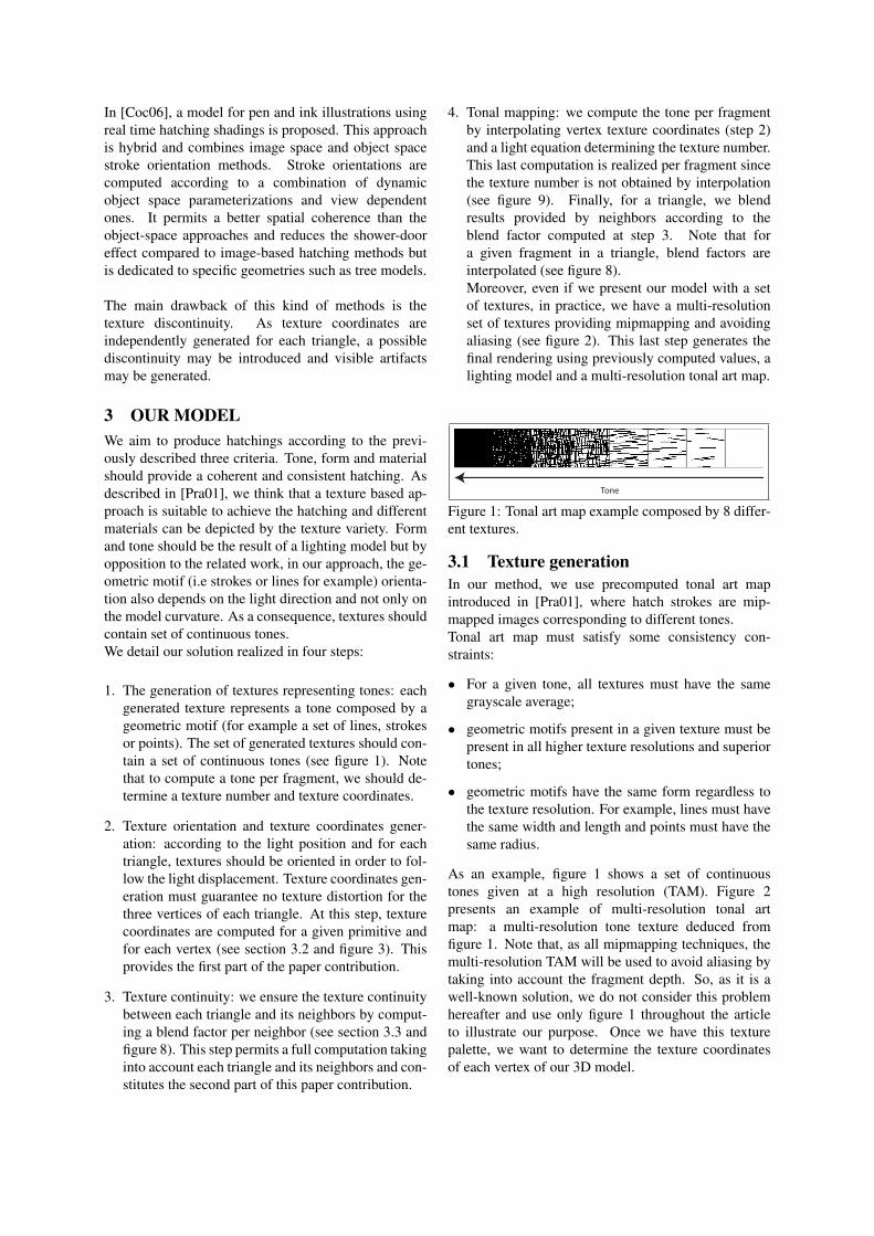
1. The generation of textures representing tones: eachgenerated texture represents a tone composed by ageometric motif (for example a set of lines, strokesor points). The set of generated textures should con-tain a set of continuous tones (see figure 1). Notethat to compute a tone per fragment, we should de-termine a texture number and texture coordinates.
2. Texture orientation and texture coordinates gener-ation: according to the light position and for eachtriangle, textures should be oriented in order to fol-low the light displacement. Texture coordinates gen-eration must guarantee no texture distortion for thethree vertices of each triangle. At this step, texturecoordinates are computed for a given primitive andfor each vertex (see section 3.2 and figure 3). Thisprovides the first part of the paper contribution.
3. Texture continuity: we ensure the texture continuitybetween each triangle and its neighbors by comput-ing a blend factor per neighbor (see section 3.3 andfigure 8). This step permits a full computation takinginto account each triangle and its neighbors and con-stitutes the second part of this paper contribution.
4. Tonal mapping: we compute the tone per fragmentby interpolating vertex texture coordinates (step 2)and a light equation determining the texture number.This last computation is realized per fragment sincethe texture number is not obtained by interpolation(see figure 9). Finally, for a triangle, we blendresults provided by neighbors according to theblend factor computed at step 3. Note that fora given fragment in a triangle, blend factors areinterpolated (see figure 8).Moreover, even if we present our model with a setof textures, in practice, we have a multi-resolutionset of textures providing mipmapping and avoidingaliasing (see figure 2). This last step generates thefinal rendering using previously computed values, alighting model and a multi-resolution tonal art map.
Tone
Figure 1: Tonal art map example composed by 8 differ-ent textures.
3.1 Texture generationIn our method, we use precomputed tonal art mapintroduced in [Pra01], where hatch strokes are mip-mapped images corresponding to different tones.Tonal art map must satisfy some consistency con-straints:
• For a given tone, all textures must have the samegrayscale average;
• geometric motifs present in a given texture must bepresent in all higher texture resolutions and superiortones;
• geometric motifs have the same form regardless tothe texture resolution. For example, lines must havethe same width and length and points must have thesame radius.
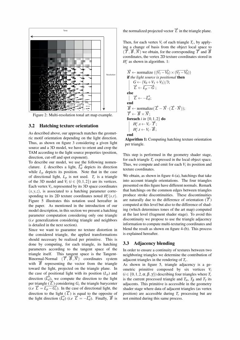
As an example, figure 1 shows a set of continuoustones given at a high resolution (TAM). Figure 2presents an example of multi-resolution tonal artmap: a multi-resolution tone texture deduced fromfigure 1. Note that, as all mipmapping techniques, themulti-resolution TAM will be used to avoid aliasing bytaking into account the fragment depth. So, as it is awell-known solution, we do not consider this problemhereafter and use only figure 1 throughout the articleto illustrate our purpose. Once we have this texturepalette, we want to determine the texture coordinatesof each vertex of our 3D model.
Tone
Resolution
Figure 2: Multi-resolution tonal art map example.
3.2 Hatching texture orientationAs described above, our approach matches the geomet-ric motif orientation depending on the light direction.Thus, as shown on figure 3 considering a given lightsource and a 3D model, we have to orient and crop theTAM according to the light source properties (position,direction, cut-off and spot exponent).To describe our model, we use the following nomen-clature. L describes a light, −→Ld depicts its directionwhile Lp depicts its position. Note that in the caseof directional light, Lp is not used. Tc is a triangleof the 3D model and Vi (i ∈ {0,1,2}) are its vertices.Each vertex Vi, represented by its 3D space coordinates(x,y,z), is associated to a hatching parameter corre-sponding to its 2D texture coordinates noted Hc
i (s, t).Figure 5 illustrates this notation used hereafter inthe paper. As mentioned in the introduction of ourmodel description, in this section we present a hatchingparameter computation considering only one triangle(i.e generalization considering triangle and neighborsis detailed in the next section).Since we want to guarantee no texture distortion inthe considered triangle, the applied transformationsshould necessary be realized per primitive. This isdone by computing, for each triangle, its hatchingparameters according to the tangent space of thetriangle itself. This tangent space is the Tangent-Binormal-Normal (
−→T ,−→B ,−→N ) coordinates system
with −→B representing the vector from the triangletoward the light, projected on the triangle plane. Inthe case of positional light with its position (Lp) anddirection (−→Ld), we compute the direction to the lightper triangle (−→L ) considering Gc the triangle barycenter(i.e −→L =
−−−−→Lp−Gc). In the case of directional light, thedirection to the light (−→L ) is equal to the opposite ofthe light direction (−→Ld) (i.e −→L = −−→Ld). Finally, −→B is
the normalized projected vector−→L in the triangle plane.
Then, for each vertex Vi of each triangle Tc, by apply-ing a change of basis from the object local space to(−→T ,−→B ,−→N ) we obtain, for the corresponding −→T and −→B
coordinates, the vertex 2D texture coordinates stored inHc
i as shown in algorithm. 1:
−→N ← normalize ((−−−−→V1−V0)× (
−−−−→V2−V0))if the light source is positional then
G← (V0 +V1 +V2)/3;−→L ←−−−−→Lp−G ;
else−→L ←−−→Ld ;
end−→B ← normalize(−→L −−→N · (−→L ·−→N ));−→T ←−→B ×−→N ;foreach i in {0,1,2} do
Hci .s←Vi ·
−→T ;Hc
i .t←Vi ·−→B ;
endAlgorithm 1: Computing hatching texture orientationper triangle.
This step is performed in the geometry shader stage,for each triangle Tc expressed in the local object space.Thus, we compute and emit for each Vi its position andtexture coordinates.
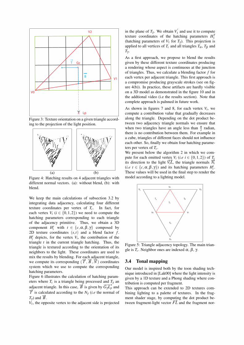
We obtain, as shown in figure 4-(a), hatchings that takeinto account triangle orientations. The four trianglespresented on this figure have different normals. Remarkthat hatchings on the common edges between trianglesproduce stroke discontinuities. These discontinuitiesare naturally due to the difference of orientation (−→T )computed at this level but also to the difference of shad-ing (which determines tones of the art map) computedat the last level (fragment shader stage). To avoid thisdiscontinuity we propose to use the triangle adjacencyinformation to compute multi-texturing coordinates andblend the result as shown on figure 4-(b). This processis explained hereafter.
3.3 Adjacency blendingIn order to ensure a continuity of textures between twoneighboring triangles we determine the contribution ofadjacent triangles in the rendering of Tc.As shown in figure 5, triangle adjacency is a ge-ometric primitive composed by six vertices Vi(i ∈ {0,1,2,α,β ,γ}) describing four triangles where Tcis the current processed triangle and Tα , Tβ and Tγ itsadjacents. This primitive is accessible in the geometryshader stage where data of adjacent triangles (as vertexposition) are accessible during Tc processing but arenot emitted during this same process.
Lp
T
B
Gc
V0
V1
V2
Figure 3: Texture orientation on a given triangle accord-ing to the projection of the light position.
(a) (b)Figure 4: Hatching results on 4 adjacent triangles withdifferent normal vectors. (a): without blend, (b): withblend.
We keep the main calculations of subsection 3.2 byintegrating data adjacency, calculating four differenttexture coordinates per vertex of Tc. In fact, foreach vertex Vi (i ∈ {0,1,2}) we need to compute thehatching parameters corresponding to each triangleof the adjacency primitive. Thus, we obtain a 3Dcomponent Ht
i with t ∈ {c,α,β ,γ} composed by2D texture coordinates (s, t) and a blend factor f .Ht
i depicts, for the vertex Vi, the contribution of thetriangle t in the current triangle hatching. Thus, thetriangle is textured according to the orientation of itsneighbors to the light. These coordinates are used tomix the results by blending. For each adjacent triangle,we compute its corresponding (
−→T ,−→B ,−→N ) coordinates
system which we use to compute the correspondinghatching parameters.Figure 6 illustrates the calculation of hatching param-eters where Tc is a triangle being processed and Tγ anadjacent triangle. In this case, −→B is given by −−−→Gγ Lp and−→T is calculated according to the Nγ (i.e the normal ofTγ ) and −→B .V1, the opposite vertex to the adjacent side is projected
in the plane of Tγ . We obtain V′1 and use it to compute
texture coordinates of the hatching parameters Hγ
1(hatching parameters of V1 for Tγ ). This projection isapplied to all vertices of Tc and all triangles Tα , Tβ andTγ .
As a first approach, we propose to blend the resultsgiven by these different texture coordinates producinga rendering whose aspect is continuous at the junctionof triangles. Thus, we calculate a blending factor f foreach vertex per adjacent triangle. This first approach isa compromise producing grayscale strokes (see on fig-ure 4(b)). In practice, these artifacts are hardly visibleon a 3D model as demonstrated in the figure 10 and inthe addtional video (i.e the results section). Note thatcomplete approach is palnned in future work.
As shown in figures 7 and 8, for each vertex Vi, wecompute a contribution value that gradually decreasesalong the triangle. Depending on the dot product be-tween two adjacency triangle normals we ensure thatwhen two triangles have an angle less than π
2 radian,there is no contribution between them. For example ina cube, triangles of different faces should not influenceeach other. So, finally we obtain four hatching parame-ters per vertex of Tc.We present below the algorithm 2 in which we com-pute for each emitted vertex Vi (i.e i ∈ {0,1,2}) of Tcits direction to the light −→ViL, the triangle normals −→Nt(i.e t ∈ {c,α,β ,γ}) and its hatching parameters Ht
i .These values will be used in the final step to render themodel according to a lighting model.
V0
V
V1
VV2
V
Tc
T
TT
α
α
β
βγ
γ
Figure 5: Triangle adjacency topology. The main trian-gle is Tc. Neighbor ones are indexed α , β , γ .
3.4 Tonal mappingOur model is inspired both by the toon shading tech-nique introduced in [Lak00] where the light intensity isgiven by a 1D texture and a Phong shading where con-tribution is computed per fragment.This approach can be extended to 2D textures com-bining lighting to a palette of textures. In the frag-ment shader stage, by computing the dot product be-tween fragment-light vector −→FL and the fragment nor-
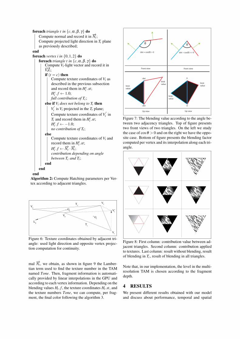
foreach triangle t in {c,α,β ,γ} doCompute normal and record it in −→Nt ;Compute projected light direction in Tt planeas previously described;
endforeach vertex i in {0,1,2} do
foreach triangle t in {c,α,β ,γ} doCompute Vi-light vector and record it in−→ViL;if (t = c) then
Compute texture coordinates of Vi asdescribed in the previous subsectionand record them in Hc
i .st;Hc
i . f ← 1.0;full contribution of Tc;
else if Vi does not belong to Tt thenV′i is Vi projected in the Tt plane;
Compute texture coordinates of V′i in
Tt and record them in Hti .st;
Hti . f ←−1.0;
no contribution of Tt ;else
Compute texture coordinates of Vi andrecord them in Ht
i .st;Ht
i . f ←−→Nc ·−→Nt ;
contribution depending on anglebetween Tc and Tt ;
endend
endAlgorithm 2: Compute Hatching parameters per Ver-tex according to adjacent triangles.
0
Tc
Gc
Lp
V’1
Vγ
Gγ
V1
V2T
γ
V
Figure 6: Texture coordinates obtained by adjacent tri-angle: used light direction and opposite vertex projec-tion computation for continuity.
mal −→Nt , we obtain, as shown in figure 9 the Lamber-tian term used to find the texture number in the TAMnamed Tone. Then, fragment information is automati-cally provided by linear interpolations in the GPU andaccording to each vertex information. Depending on theblending values Ht . f , the texture coordinates Ht .st, andthe texture numbers Tone, we can compute, per frag-ment, the final color following the algorithm 3.
dot = cos(θ) > 0
dot
dot
limit
value
0
0
limit
value
Front view Front view
Up view Up view
dot = cos(θ) <= 0
θ θ
limit
value
limit
value
Figure 7: The blending value according to the angle be-tween two adjacency triangles. Top of figure presentstwo front views of two triangles. On the left we studythe case of cosθ > 0 and on the right we have the oppo-site case. Bottom of figure presents the blending factorcomputed per vertex and its interpolation along each tri-angle.
Figure 8: First column: contribution value between ad-jacent triangles. Second column: contribution appliedto textures. Last column: result without blending, resultof blending in Tc, result of blending in all triangles.
Note that, in our implementation, the level in the multi-resolution TAM is chosen according to the fragmentdepth.
4 RESULTSWe present different results obtained with our modeland discuss about performance, temporal and spatial
foreach triangle t in {c,α,β ,γ} doCompute Tone according to −→Nt and −→FL;Compute Colort determined by Ht .st and Tone;
endFinalColor← ∑(Colort ×Ht . f )/∑(Ht . f ) ;
Algorithm 3: Compute the fragment color
A
B C
A
B C
A
B C
LIGHT POSITION
Phong ShadingGouraud shading
LIGHT POSITION
A
CB
Front viewpoint
Up viewpoint
Figure 9: Example of texture number determining perfragment with different lighting techniques
coherence during scene animations.
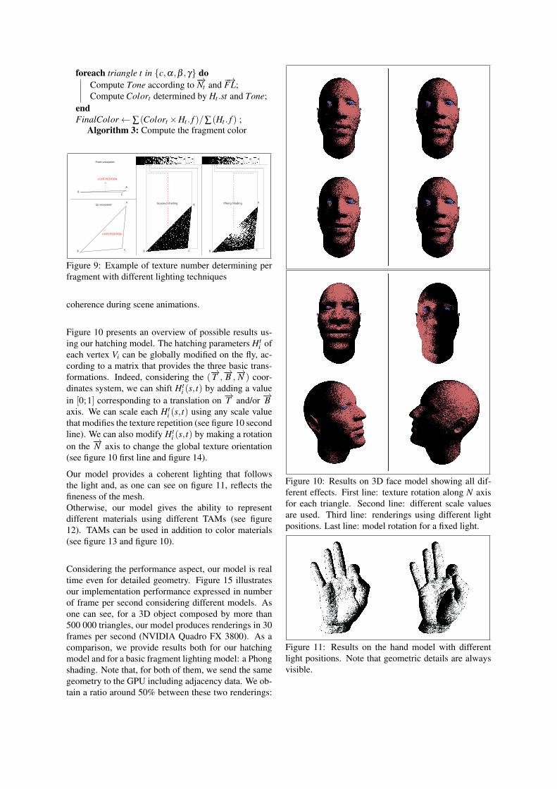
Figure 10 presents an overview of possible results us-ing our hatching model. The hatching parameters Ht
i ofeach vertex Vi can be globally modified on the fly, ac-cording to a matrix that provides the three basic trans-formations. Indeed, considering the (
−→T ,−→B ,−→N ) coor-
dinates system, we can shift Hti (s, t) by adding a value
in [0;1] corresponding to a translation on −→T and/or −→Baxis. We can scale each Ht
i (s, t) using any scale valuethat modifies the texture repetition (see figure 10 secondline). We can also modify Ht
i (s, t) by making a rotationon the −→N axis to change the global texture orientation(see figure 10 first line and figure 14).
Our model provides a coherent lighting that followsthe light and, as one can see on figure 11, reflects thefineness of the mesh.Otherwise, our model gives the ability to representdifferent materials using different TAMs (see figure12). TAMs can be used in addition to color materials(see figure 13 and figure 10).
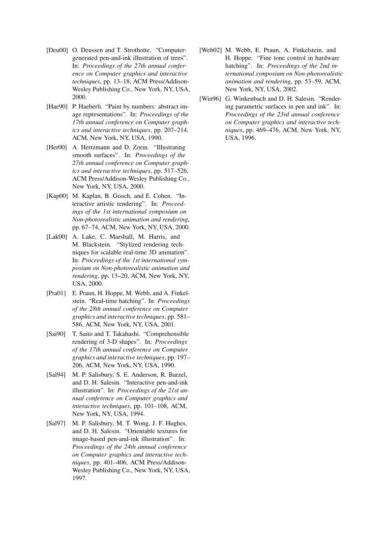
Considering the performance aspect, our model is realtime even for detailed geometry. Figure 15 illustratesour implementation performance expressed in numberof frame per second considering different models. Asone can see, for a 3D object composed by more than500 000 triangles, our model produces renderings in 30frames per second (NVIDIA Quadro FX 3800). As acomparison, we provide results both for our hatchingmodel and for a basic fragment lighting model: a Phongshading. Note that, for both of them, we send the samegeometry to the GPU including adjacency data. We ob-tain a ratio around 50% between these two renderings:
Figure 10: Results on 3D face model showing all dif-ferent effects. First line: texture rotation along N axisfor each triangle. Second line: different scale valuesare used. Third line: renderings using different lightpositions. Last line: model rotation for a fixed light.
Figure 11: Results on the hand model with differentlight positions. Note that geometric details are alwaysvisible.
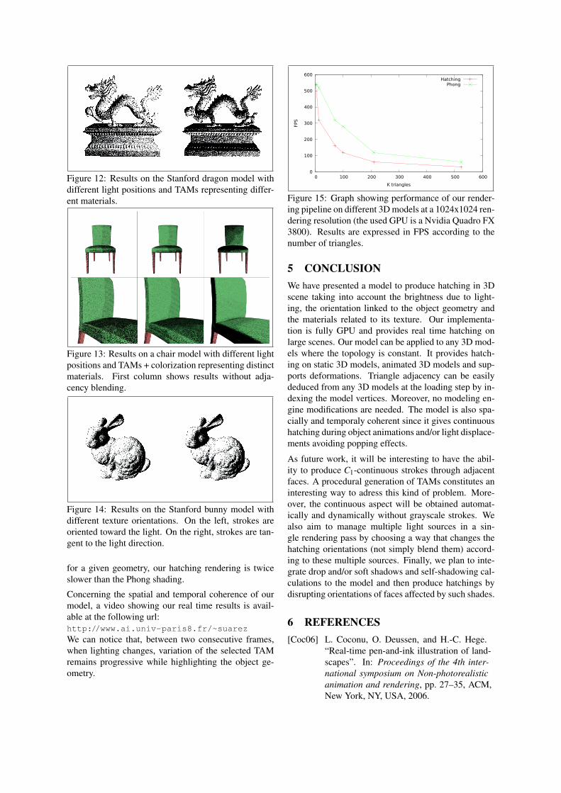
Figure 12: Results on the Stanford dragon model withdifferent light positions and TAMs representing differ-ent materials.
Figure 13: Results on a chair model with different lightpositions and TAMs + colorization representing distinctmaterials. First column shows results without adja-cency blending.
Figure 14: Results on the Stanford bunny model withdifferent texture orientations. On the left, strokes areoriented toward the light. On the right, strokes are tan-gent to the light direction.
for a given geometry, our hatching rendering is twiceslower than the Phong shading.
Concerning the spatial and temporal coherence of ourmodel, a video showing our real time results is avail-able at the following url:http://www.ai.univ-paris8.fr/~suarez
We can notice that, between two consecutive frames,when lighting changes, variation of the selected TAMremains progressive while highlighting the object ge-ometry.
0
100
200
300
400
500
600
0 100 200 300 400 500 600
FPS
K triangles
HatchingPhong
Figure 15: Graph showing performance of our render-ing pipeline on different 3D models at a 1024x1024 ren-dering resolution (the used GPU is a Nvidia Quadro FX3800). Results are expressed in FPS according to thenumber of triangles.
5 CONCLUSIONWe have presented a model to produce hatching in 3Dscene taking into account the brightness due to light-ing, the orientation linked to the object geometry andthe materials related to its texture. Our implementa-tion is fully GPU and provides real time hatching onlarge scenes. Our model can be applied to any 3D mod-els where the topology is constant. It provides hatch-ing on static 3D models, animated 3D models and sup-ports deformations. Triangle adjacency can be easilydeduced from any 3D models at the loading step by in-dexing the model vertices. Moreover, no modeling en-gine modifications are needed. The model is also spa-cially and temporaly coherent since it gives continuoushatching during object animations and/or light displace-ments avoiding popping effects.
As future work, it will be interesting to have the abil-ity to produce C1-continuous strokes through adjacentfaces. A procedural generation of TAMs constitutes aninteresting way to adress this kind of problem. More-over, the continuous aspect will be obtained automat-ically and dynamically without grayscale strokes. Wealso aim to manage multiple light sources in a sin-gle rendering pass by choosing a way that changes thehatching orientations (not simply blend them) accord-ing to these multiple sources. Finally, we plan to inte-grate drop and/or soft shadows and self-shadowing cal-culations to the model and then produce hatchings bydisrupting orientations of faces affected by such shades.
6 REFERENCES[Coc06] L. Coconu, O. Deussen, and H.-C. Hege.
“Real-time pen-and-ink illustration of land-scapes”. In: Proceedings of the 4th inter-national symposium on Non-photorealisticanimation and rendering, pp. 27–35, ACM,New York, NY, USA, 2006.
[Deu00] O. Deussen and T. Strothotte. “Computer-generated pen-and-ink illustration of trees”.In: Proceedings of the 27th annual confer-ence on Computer graphics and interactivetechniques, pp. 13–18, ACM Press/Addison-Wesley Publishing Co., New York, NY, USA,2000.
[Hae90] P. Haeberli. “Paint by numbers: abstract im-age representations”. In: Proceedings of the17th annual conference on Computer graph-ics and interactive techniques, pp. 207–214,ACM, New York, NY, USA, 1990.
[Her00] A. Hertzmann and D. Zorin. “Illustratingsmooth surfaces”. In: Proceedings of the27th annual conference on Computer graph-ics and interactive techniques, pp. 517–526,ACM Press/Addison-Wesley Publishing Co.,New York, NY, USA, 2000.
[Kap00] M. Kaplan, B. Gooch, and E. Cohen. “In-teractive artistic rendering”. In: Proceed-ings of the 1st international symposium onNon-photorealistic animation and rendering,pp. 67–74, ACM, New York, NY, USA, 2000.
[Lak00] A. Lake, C. Marshall, M. Harris, andM. Blackstein. “Stylized rendering tech-niques for scalable real-time 3D animation”.In: Proceedings of the 1st international sym-posium on Non-photorealistic animation andrendering, pp. 13–20, ACM, New York, NY,USA, 2000.
[Pra01] E. Praun, H. Hoppe, M. Webb, and A. Finkel-stein. “Real-time hatching”. In: Proceedingsof the 28th annual conference on Computergraphics and interactive techniques, pp. 581–586, ACM, New York, NY, USA, 2001.
[Sai90] T. Saito and T. Takahashi. “Comprehensiblerendering of 3-D shapes”. In: Proceedingsof the 17th annual conference on Computergraphics and interactive techniques, pp. 197–206, ACM, New York, NY, USA, 1990.
[Sal94] M. P. Salisbury, S. E. Anderson, R. Barzel,and D. H. Salesin. “Interactive pen-and-inkillustration”. In: Proceedings of the 21st an-nual conference on Computer graphics andinteractive techniques, pp. 101–108, ACM,New York, NY, USA, 1994.
[Sal97] M. P. Salisbury, M. T. Wong, J. F. Hughes,and D. H. Salesin. “Orientable textures forimage-based pen-and-ink illustration”. In:Proceedings of the 24th annual conferenceon Computer graphics and interactive tech-niques, pp. 401–406, ACM Press/Addison-Wesley Publishing Co., New York, NY, USA,1997.
[Web02] M. Webb, E. Praun, A. Finkelstein, andH. Hoppe. “Fine tone control in hardwarehatching”. In: Proceedings of the 2nd in-ternational symposium on Non-photorealisticanimation and rendering, pp. 53–59, ACM,New York, NY, USA, 2002.
[Win96] G. Winkenbach and D. H. Salesin. “Render-ing parametric surfaces in pen and ink”. In:Proceedings of the 23rd annual conferenceon Computer graphics and interactive tech-niques, pp. 469–476, ACM, New York, NY,USA, 1996.