Goal andga oct01
36
Global Observations and Alerts from Lagrange-point, Pole-sitter, and Geosynchronous Orbits (GOAL&GO) a revolutionary measurement concept that will provide a new capability for humankind to monitor the Earth as it responds to anthropogenically–induced global climate change Dr. Larry J. Paxton Dr. Jeng-Hwa Yee Dr. Daniel Morrison The Johns Hopkins University Applied Physics Laboratory 11100 Johns Hopkins Rd. Laurel, MD 20723 [email protected] 240 228 6871 240 228 6670 fax
-
Upload
clifford-stone -
Category
Documents
-
view
112 -
download
0
Transcript of Goal andga oct01

Global Observations and Alerts from Lagrange-point,
Pole-sitter, and Geosynchronous Orbits (GOAL&GO)
a revolutionary measurement concept that will provide a new capability for humankind to monitor the Earth as it responds to anthropogenically–induced global climate change
Dr. Larry J. PaxtonDr. Jeng-Hwa YeeDr. Daniel Morrison
The Johns Hopkins UniversityApplied Physics Laboratory11100 Johns Hopkins Rd.
Laurel, MD [email protected]
240 228 6871240 228 6670 fax
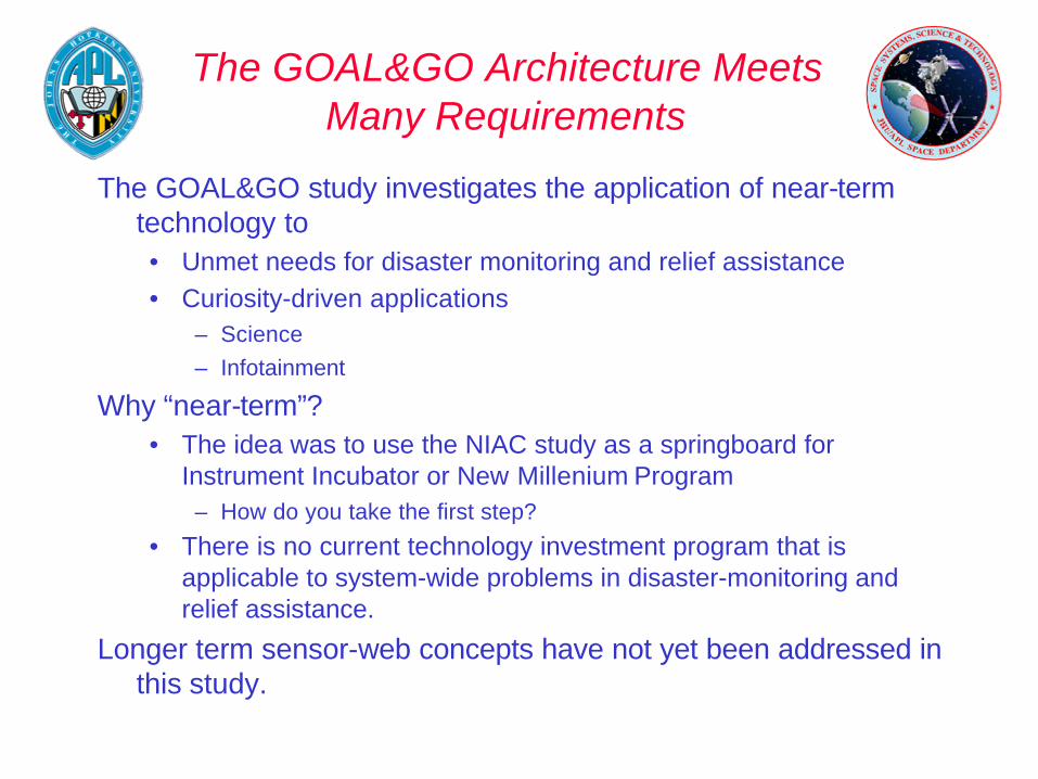
The GOAL&GO Architecture Meets Many Requirements
The GOAL&GO study investigates the application of near-term technology to• Unmet needs for disaster monitoring and relief assistance• Curiosity-driven applications
– Science– Infotainment
Why “near-term”?• The idea was to use the NIAC study as a springboard for
Instrument Incubator or New Millenium Program– How do you take the first step?
• There is no current technology investment program that is applicable to system-wide problems in disaster-monitoring and relief assistance.
Longer term sensor-web concepts have not yet been addressed in this study.
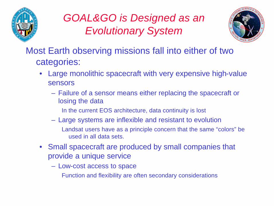
GOAL&GO is Designed as an Evolutionary System
Most Earth observing missions fall into either of two categories:• Large monolithic spacecraft with very expensive high-value
sensors– Failure of a sensor means either replacing the spacecraft or
losing the dataIn the current EOS architecture, data continuity is lost
– Large systems are inflexible and resistant to evolutionLandsat users have as a principle concern that the same “colors” be
used in all data sets.
• Small spacecraft are produced by small companies that provide a unique service– Low-cost access to space
Function and flexibility are often secondary considerations

Disaster Monitoring and Relief Assistance Begins With Avoidance
Hazard mitigation is the first step• Can the scope of a disaster be reduced by providing timely,
accurate, and adequate warning?– What are the features that must be monitored?
• Can planning information be provided and disseminated?– Escape routes– Avoidance of threatened areas
Disaster monitoring provides hazard warnings for areas not yet affected.
Relief assistance may require data that has not been heretofore available or that may have recently changed.• Some applications (e.g. trafficability) may require very high
resolution imagery

GOAL&GO is Revolutionary
The GOAL&GO study is intended to look at ways in which we can change the way that most of the human race sees the world.• Time frame is 10 – 20 years
The majority of the Earth’s population and governments still have a very limited view of the world and how what happens in one part of the world effects another.
Many nations seek a space presence.• How can the cost be kept low?• How can success be assured and risk reduced?• How can a valuable service be provided?
– Can information be revolutionary?

The GOAL&GO Architecture Uses Simple Elements to Respond to System-wide Requirements
VISHNU and SHIVAOn Polesitter
SHIVA 1
SHIVA 4 SHIVA 3
Functional RequirementsPerformance
Resolution
Data AvailabilityData Distribution
Maximize Utility
OperationalData Content Maximized
Data Downlink MinimizedMinimize Data Latency
Autonomy MaximizedConstraints
Minimize Cost
Minimize Impact on HostSpacecraft
Real-time Command and Control
Space Segment ResourceRequirements Ground System Resource
Requirements
Payload Flexibilityand Autonomy
Data Utility and Access
Geostationaryorbit
SHIVA 2SHIVA 5
VISHNU and SHIVAOn Polesitter
MeasurementRequirementsfor ScienceandApplications
Coverage: Temporal,Spatial, Spectral
VISHNU L1 VISHNU L2
The “full-up” constellation is shown with the major external drivers and functional requirements.

GOAL&GO Can Address ESE Key Areas
Tropospheric plume transport on scales from 250 m to 100s of km, total ozone
Ozone/Atmospheric Chemistry
Water vapor, cloud heights, aerosols, albedo
Atmospheric Climate and Water Cycle
Ocean and land albedo and ocean productivity mapping and change detection
Ocean and Polar Science
Vegetation index, biomass burning, fire occurrence and frequency, urbanization via city lights
Land Cover and Land Use
Volcanic ash detection and tracking, severe storm studies and tracking, fire and flood forecast, extent and progress, volcanic eruption detection and plume forecast
Natural Hazards and Solid Earth
1 These thrust areas are delineated in the ESE Strategic Plan (2000) see also www.earth.nasa.gov/science/index.html.

GOAL&GO Sensor-web Requirements are Manageable
“Overarching” drivers for the design are• Design an expandable architecture• Use simple subsystems• Reuse “heritage” technology as much as possible• Design to minimize the impact of the sensors on the bus
– Reduce power– Reduce mass– Reduce pointing requirements– Reduce downlink requirements– Manage uplink requirements
• Enable system elements to be controlled by the “user”– Reduce complexity at all levels– Reuse software

Enabling Technologies
Allows improved performance by enabling pointing of FOV over large angular range
High–displacement piezoelectric actuators
Pointing of the SHIVA system
Enhanced science synergy by adding to effective instrument complement of existing platforms by simultaneous sampling of the common volume
Virtual platformCoordination with EOS/ESSP missions (and follow-ons)
Enables remote users to configure SHIVA and collect data over their site
Science from a LaptopCapture and use of custom data sets by remote user
Reduces requirement for data review by indicating when hazard has been detected – designed for S/C could be applied to data stream
Onboard Engineering Data Summarization and Beacon (hazard “pager”)
Scene selection and real–time hazard warning
Enables SHIVA and VISHNU sensors to continuously obtain undistorted, high resolution views of polar regions
Solar sail technologyPole-sitter orbit maintenance
Enables scene selection for cueing of SHIVA by VISHNU (or other means) and adjustment of SHIVA FOV
Science feature extractionRealtime hazard monitoring and detection
ImpactEnabling Technology to be Evaluated1
System Driver
1 These categories map to the general categories and themes in the New Millenium Program

Enabling Technologies
Enables implementation on a wider range of buses and potentially decreases requirements on ground segment
Deployable comm antennaRF communications from HEO while minimizing package size
Reduces downlink requirementsHigh rate channel codingData rate reduction
Reduces package size while meeting science driver for resolution and collecting area
Deployable mirrorLarge aperture precision mirror
Allows use on off–the–shelf spacecraftHigh precision pointing and stabilization of mirrors
Spacecraft stability –Jitter requirement reduction
Reduces downlink requirements enabling lower transmitter power and/or receiver dish diameter
High performance data compression (HPDC)
Data rate reduction
Enables the SHIVA high spatial resolution Fabry-Perot cloud height sensor by minimizing integration period and maximizing SNR
Deployable, large diameter, high precision optical elements
Maximize collecting aperture for high spectral resolution measurements
Improves performance of backend of system and enables ground resolution requirements to be met
Silicon Carbide Mirrors and Structures
Stability of fast high angular resolution optics
ImpactEnabling Technology to be Evaluated1
System Driver

Enabling Technologies
Enables fire detection mission for SHIVA with accurate cloud removal
Large format SWIR/MWIR InSb arrays
Imaging of thermal radiation
Provides science flexibility and meets SNR requirements for images while reducing jitter spec by allowing longer effective integration period than spectrographs or other scanning or rastering systems
Liquid crystal tunable filterSelectable bandpass for imager
Reduces power requirement and volume for star camera for pointing knowledge and CCD for science
Chip–on–board CameraMinimizing camera size
Provides cooling for SHIVA fire detection arrayLow T Long–life Cryocoolers – solid state?
Low temperature IR focal planes
Transports large amounts of data for image processing in space required to reduce downlink volume and produces products
Spaceborne fiber optic data bus (SFODB)Rad-hard Pentium-class CPU
On–board image processing
ImpactEnabling Technology to be Evaluated1
System Driver

L1 Orbit is Well-suited to Context-Setting Earth Observations
Figure from http://triana.gsfc.nasa.gov/instruments/lagrange.htm
L1 provides a more complete image of the disk of the Earth (about 8 deg more than geosynch) but• the principle advantage is that it always samples near local
noon• The globe equatorward of 60 deg can be imaged,
continuously.
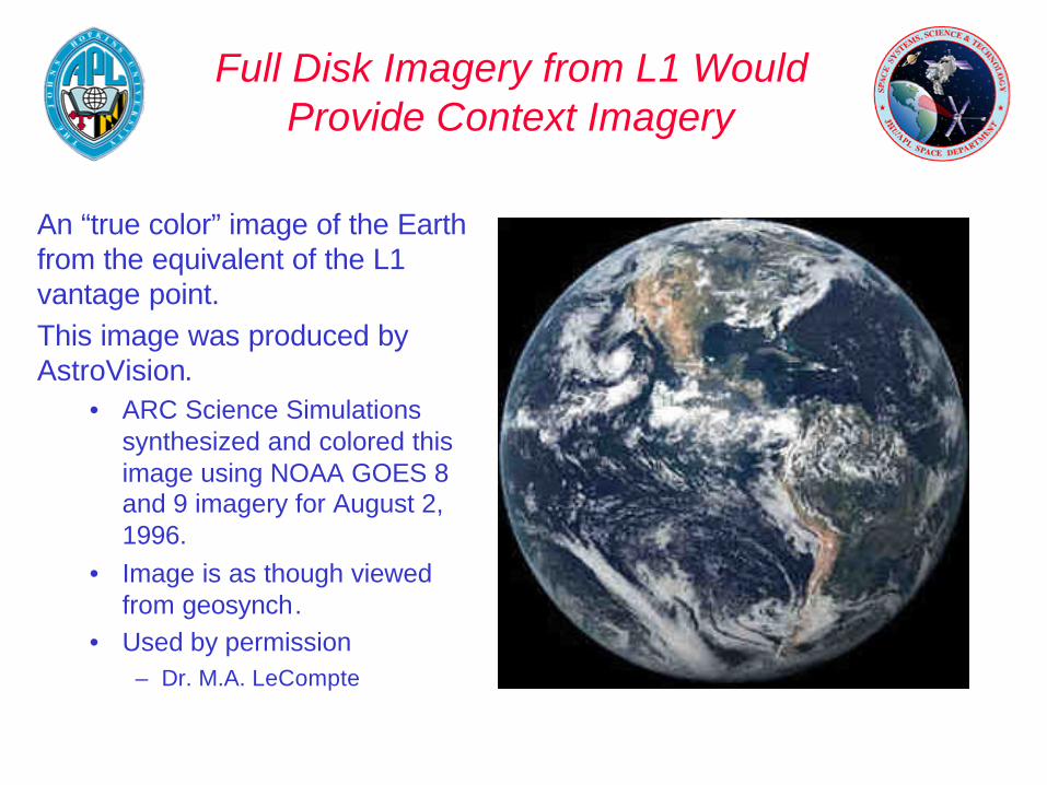
Full Disk Imagery from L1 Would Provide Context Imagery
An “true color” image of the Earth from the equivalent of the L1 vantage point.This image was produced by AstroVision.
• ARC Science Simulations synthesized and colored this image using NOAA GOES 8 and 9 imagery for August 2, 1996.
• Image is as though viewed from geosynch.
• Used by permission– Dr. M.A. LeCompte

L1 Provides Continuous Near-Noon Viewing Geometry
The TRIANA mission was intended to take advantage of this viewing geometry to obtain images of the Earth• in 10 wavelength intervals • at 8 km resolution• required 1.3 m antenna on s/c with 13 m antenna on the
ground• 100 to 200 kbps downlink rate or 10 min/image refresh rate

TRIANA was a Low-cost Mission –Less Than $100M
TRIANA had a very limited wavelength coverage• Originally the instrument was to have an IR capability• IR is currently not available on global scales at the resolution and
wavelengths required for many applications– NISTAR was to measure the Earth’s flux
8Water Vapor15905
8Clouds15869.5
8Red, Aerosols10645
8Green, Aerosols10551
8Blue, Aerosols10443
8Cloud Height1393.5
8Aerosols, Clouds5388
8Aerosols5340
8 Ozone, SO21325
8Ozone1317.5
kmnmnm
Spatial resolutionPurposeBandwidthWavelengths
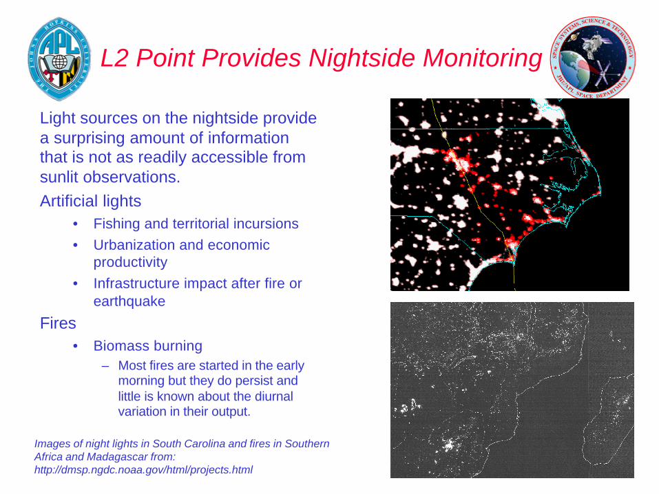
L2 Point Provides Nightside Monitoring
Light sources on the nightside provide a surprising amount of information that is not as readily accessible from sunlit observations.Artificial lights
• Fishing and territorial incursions• Urbanization and economic
productivity• Infrastructure impact after fire or
earthquake
Fires• Biomass burning
– Most fires are started in the early morning but they do persist and little is known about the diurnal variation in their output.
Images of night lights in South Carolina and fires in Southern Africa and Madagascar from:http://dmsp.ngdc.noaa.gov/html/projects.html

Geosynchronous Orbit is Very Accessible
Geosynchronous orbit gives nearly the same coverage as from L1 but it is tied to a single location. • The advantage is that you have continuous coverage at all
local times.• Important for applications driven by the desire to see a
particular area at all times.
Dedicated spacecraft at geosynch are very expensive (of the order of $100M) but• Many spacecraft vendors have space available for payloads
that do not impose a significant burden on the host.• Vendors have proliferated even though business forecasts for
comm usage appear down from previous years.– Ground infrastructure is taking up some of the “bandwidth”.
Satellite Users Have New Resources Available to Them
The old paradigm is that a user had to be tied closely to the spacecraft vendor now commercial or scientific users can look at “catalogs” of vendors• GSFC Rapid Spacecraft Development Office • http://rsdo.gsfc.nasa.gov/
Small venture-capital funded firms are able to consider a presence at geosynch with the latest application being optical imaging• Astrovision, Inc. is looking at the “infotainment” value of
geosynch images as well as their scientific application• http://www.astrovision.com/

Geosynch Provides the Nearly Ideal Platform for Observations Tied to a Particular Location
Geosynch provides the opportunity to monitor the time dependent behavior of a physical phenomena
• Low-Earth orbits tend to have issues with aliasing of time-periodic phenomena
• We need extended datasets to build up data climatologiesfor inaccessible or less developed regions.
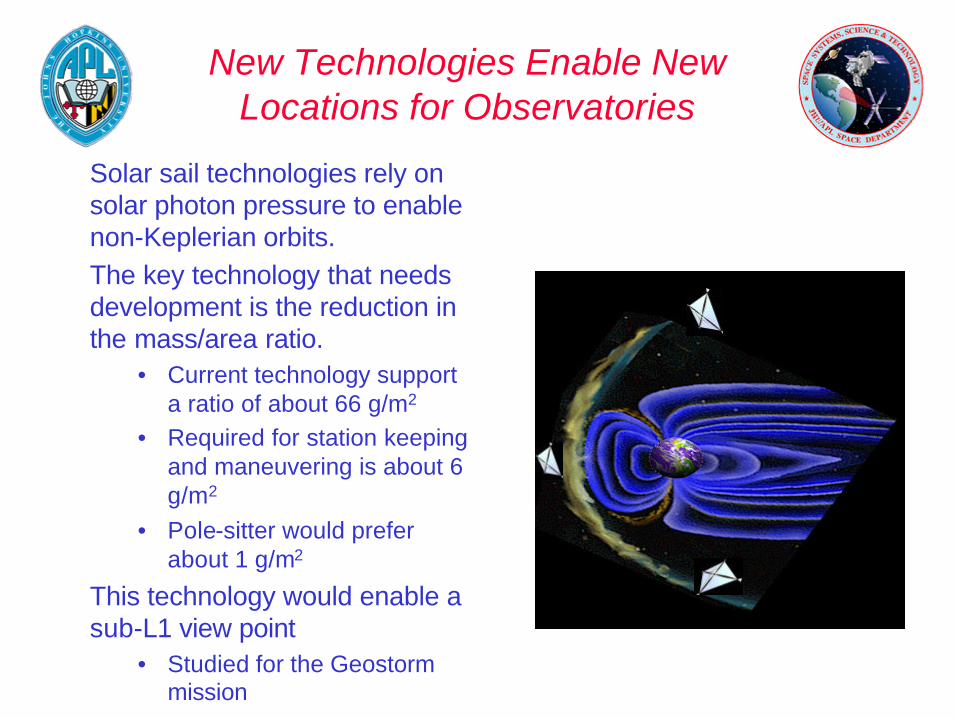
New Technologies Enable New Locations for Observatories
Solar sail technologies rely on solar photon pressure to enable non-Keplerian orbits.The key technology that needs development is the reduction in the mass/area ratio.
• Current technology support a ratio of about 66 g/m2
• Required for station keeping and maneuvering is about 6 g/m2
• Pole-sitter would prefer about 1 g/m2
This technology would enable a sub-L1 view point
• Studied for the Geostormmission

NASA’s Living With A Star Program Takes Advantage of “Novel” Orbits
Solar Polar Orbiter
L3 Solar Sentinel
Solar Dynamics Observatory
North Pole Sitter
South Pole Sitter
Radiation Belt Mappers
Ionospheric Mappers
L4 Solar Sentinel
L5 Solar Sentinel
L2
Geostorm (Sub L1)
Slide courtesy George Withbroe
We Live in Interesting Times
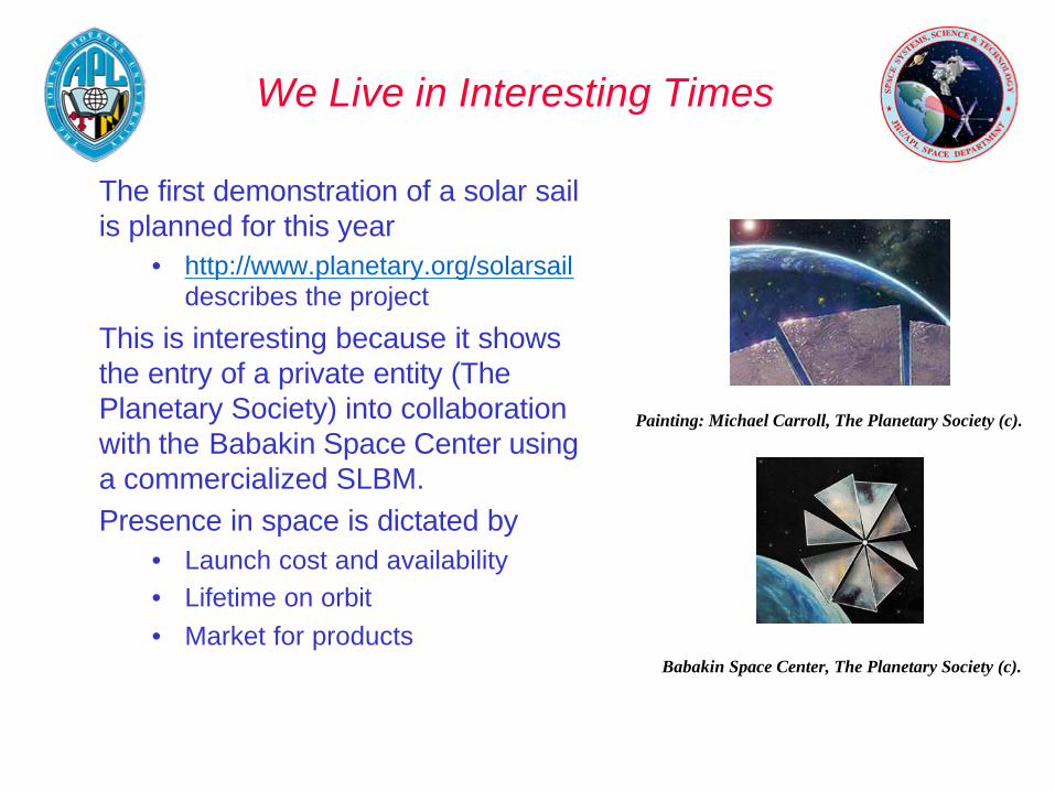
The first demonstration of a solar sail is planned for this year
• http://www.planetary.org/solarsaildescribes the project
This is interesting because it shows the entry of a private entity (The Planetary Society) into collaboration with the Babakin Space Center using a commercialized SLBM.Presence in space is dictated by
• Launch cost and availability• Lifetime on orbit• Market for products
Painting: Michael Carroll, The Planetary Society (c).
Babakin Space Center, The Planetary Society (c).
GOAL&GO Will Use a SteerableImaging System and On-board Processing to Deliver Tailored
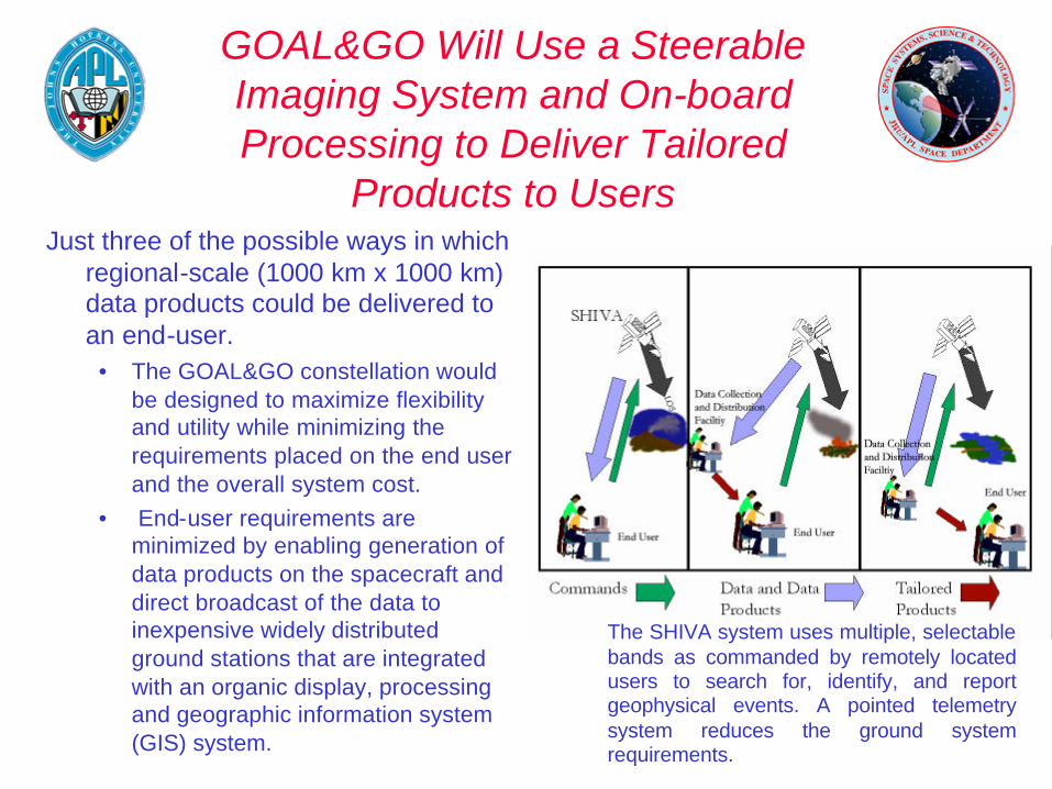
Products to UsersJust three of the possible ways in which
regional-scale (1000 km x 1000 km) data products could be delivered to an end-user.
• The GOAL&GO constellation would be designed to maximize flexibility and utility while minimizing the requirements placed on the end user and the overall system cost.
• End-user requirements are minimized by enabling generation of data products on the spacecraft and direct broadcast of the data to inexpensive widely distributed ground stations that are integrated with an organic display, processing and geographic information system (GIS) system.
The SHIVA system uses multiple, selectable bands as commanded by remotely located users to search for, identify, and report geophysical events. A pointed telemetry system reduces the ground system requirements.
The “Bits-to-Parameters” Problem is Well in Hand
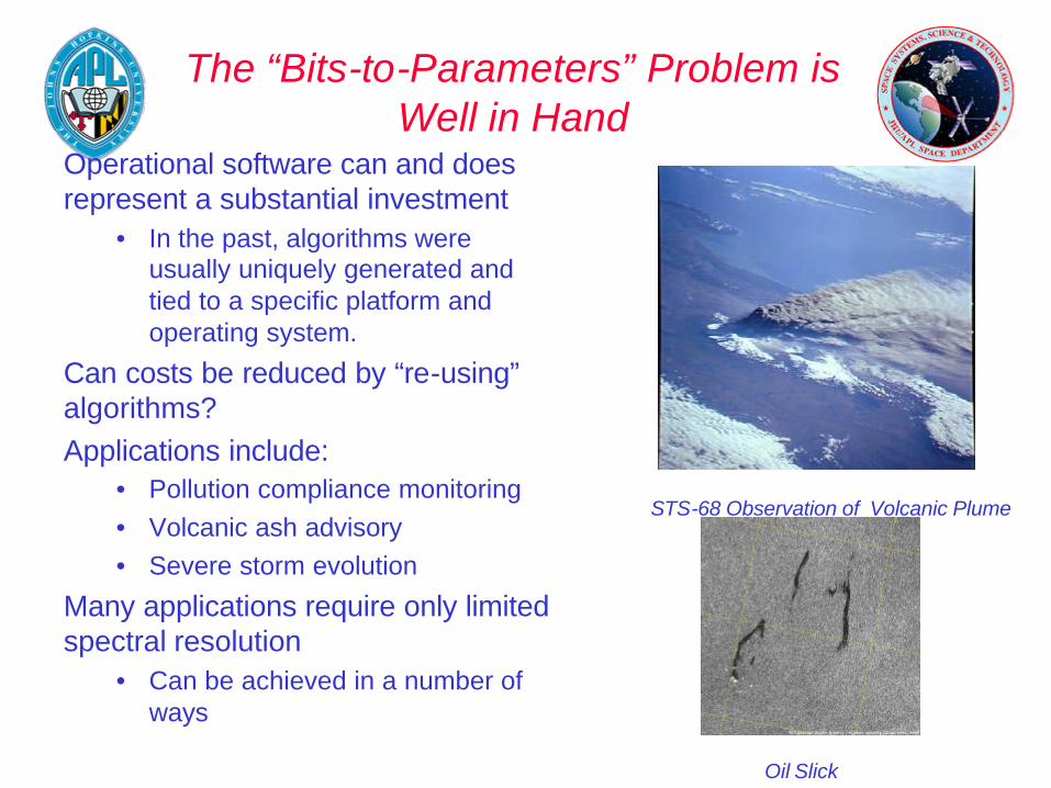
Operational software can and does represent a substantial investment
• In the past, algorithms were usually uniquely generated and tied to a specific platform and operating system.
Can costs be reduced by “re-using” algorithms?Applications include:
• Pollution compliance monitoring• Volcanic ash advisory• Severe storm evolution
Many applications require only limited spectral resolution
• Can be achieved in a number of ways
STS-68 Observation of Volcanic Plume
Oil Slick
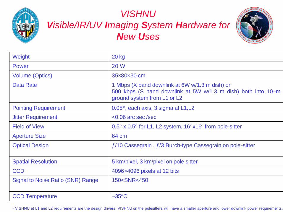
VISHNUVisible/IR/UV Imaging System Hardware for
New Uses
–35°CCCD Temperature
150<SNR<450Signal to Noise Ratio (SNR) Range
4096×4096 pixels at 12 bitsCCD
5 km/pixel, 3 km/pixel on pole sitterSpatial Resolution
ƒ/10 Cassegrain , ƒ/3 Burch-type Cassegrain on pole-sitterOptical Design
64 cmAperture Size
0.5° x 0.5° for L1, L2 system, 16°x16° from pole-sitterField of View
<0.06 arc sec /secJitter Requirement
0.05°, each axis, 3 sigma at L1,L2Pointing Requirement
1 Mbps (X band downlink at 6W w/1.3 m dish) or500 kbps (S band downlink at 5W w/1.3 m dish) both into 10–m ground system from L1 or L2
Data Rate
35×80×30 cmVolume (Optics)
20 W Power
20 kgWeight
1 VISHNU at L1 and L2 requirements are the design drivers. VISHNU on the polesitters will have a smaller aperture and lower downlink power requirements.

SHIVASupporting High–resolution IR Visible
Applications (SHIVA)
160<SNR<2040InSb Fire Detection SNR range
70 KInSb Array Temperature
4096×4096 pixels1 at 12 bitsInSb Array
–35° CCCD Temperature
500<SNR<4000CCD Signal to Noise Ratio (SNR) range
4096×4096 pixels at 12 bitsCCD
250 meters/pixelSpatial Resolution
ƒ/2.2 Cassegrain (with electro–optical shutter)Optical Design
100 cmAperture Size
20°Field of Regard
1.5° x 1.5°Field of View
<0.4 arc sec /secJitter Requirement
0.05°, each axis, 3 sigmaPointing Requirement
1Mbps (S band into 0.5 m receiver)Data Rate
35×80×30 cmVolume (Optics)
20 W Power
20 kgWeight
1Array size could be decreased resulting in smaller sampled fire detection area

VISHNU and SHIVA Bands (Example LCTF Band
Identifications1,2)Table 4.
water vapor, albedo – MODIS band 19, AVHRR935 nm
ocean color – SeaWIFS band 8865 nm
water vapor, albedo – MODIS band 2855 nm
Lightning – nightside observations with SHIVA only (dayside requires high rejection filter)774 nm
ocean color – SeaWiFS band 7765 nm
ocean color – SeaWiFS band 6670 nm
vegetation, albedo, and clouds – MODIS band 1, AVHRR645 nm
vegetation, ocean color, albedo – MODIS band 4, SeaWiFS band 5555 nm
ocean color – SeaWiFS band 4510 nm
ocean color – SeaWiFS band 3490 nm
vegetation, albedo – MODIS band 3465 nm
ocean color – SeaWiFS band 2443 nm
ocean color – SeaWiFS band 1412 nm
UV/A, aerosols, ocean color, clouds – TOMS wavelengths400 nm
Raman scattering cloud height 395 nm
Aerosols and Ozone –TOMS wavelength340 nm
UV/B, Ozone – TOMS wavelength317 nm
1 5 nm bandwidth gives the required spectral resolution – many uses (AVHRR, MODIS, SeaWiFS) require only 10 to 40 nm resolution2 EOS instrument acronym definitions, descriptions and bands found in 1997 MTPE EOS Data Products Handbook, 1997 and EOS Reference Handbook, 1999

Light Path Can Accommodate Additional Detectors and Filter
AssembliesVISHNU Dedicated Filters for Second Camera
dayside lightning sensor (0.2nm width)777.4 nm
albedo for cloud height algorithm (0.2 nm width)760.7 nm
cloud height determination from O2 Atmospheric band (0.2 nm width)762.0 nm
Raman scattering infill for cloud height (0.5 nm width)393.3 nm
SHIVA Fire Detection Bands and Uses for Second Camera
active fires, burn scars – MODIS band 203.7 µm
burn scars, active fires2.5 µm
vegetation stress, burn scars (differentiated from water) – MODIS Band 72.2 µm
aerosol optical depth, vegetation stress – MODIS Band 61.7 µm
cirrus cloud detection – MODIS Band 261.38 µm

Imager Steering and Stabilization Design Leverages SCHOONERS IIP
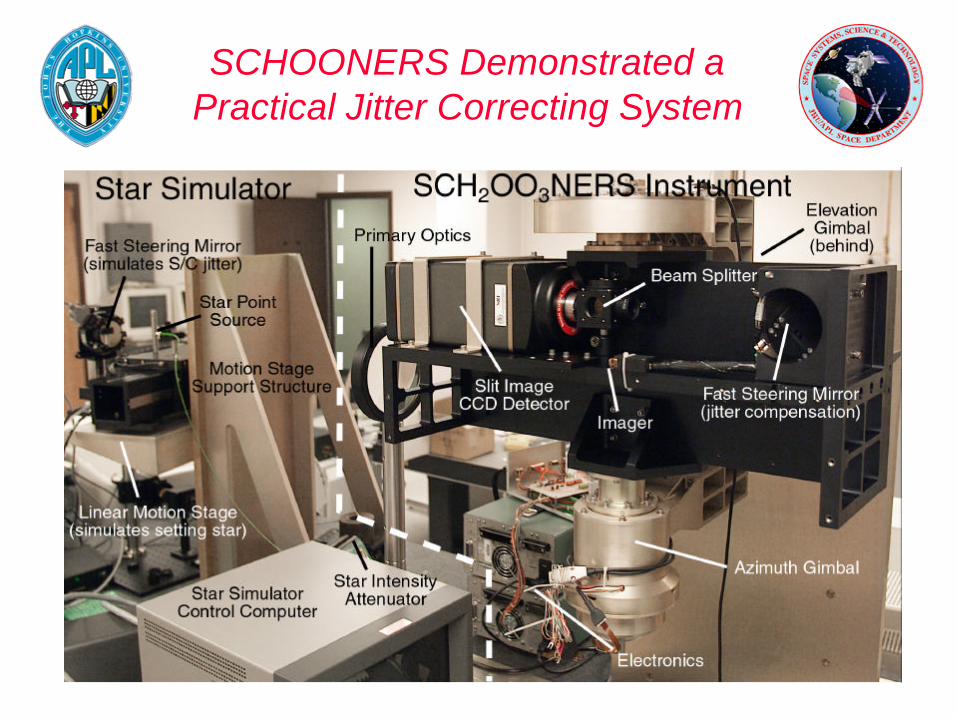
SCHOONERS Demonstrated a Practical Jitter Correcting System

SCHOONERS Demonstrates Key GOAL&GO Pointing and Control
Technologies
The SCHOONERS systems is designed to obtain spectral images of stars, from the Space Station, as the star sets through the atmosphere.
SCHOONERS demonstrated• 100 Hz tracking correction• Azimuth and elevation slew control to 0.1 arcsec over ±15°• Control algorithms
– Running on a Pentium III
• System could be isolated from larger and small scale motions of the platform

GIFTS-IOMI Will Demonstrate the Concept of a Self-Pointed Imager Operated at Geo
See: http://nmp.jpl.nasa.gov/eo3/tech/gifts.html
The Next Step
The “ideal” systems for basic research and disaster monitoring diverge on the issue of resolution:• Basic research is often concerned with increasing spectral
resolution– Variations in the radiance with optical depth give you the means
to retrieve vertical information in the atmosphere
• Image-based applications are concerned with spatial resolution where individual physical features need to be detected. – Is synthetic aperture imaging from geo the next step?
These “ideal” systems will have very high data rates to handle and will require very fast rad-hard processors and bus architectures.
Data Rate is not a Constraint for the Basic System
In the ideal, intelligent, reconfigurable system, the data rate will be very high.
A globe-spanning sensor web could be formed that includes the GOAL&GO architecture and augments this with• Long-duration high altitude UAV providing high resolution
local data• Distributed networks of tropospheric weather sensors, in
space and on the ground, driving mesoscale forecast models• Active remote sensing platforms providing “ancillary”
information– SAR for soil moisture and biomass– Laser-sounding for winds, trace constituents, altimetry, and
aerosols
Data Usage for an Integrated System Will Eventually Drive the Technology
Data rates and volumes are probably more easily addressed (i.e. more technology) than• Cultural differences
– Formatting and platform differences– Visualization and maping
• Knowledge extraction– Metadata access– Data mining and information harvesting– Archiving baseline datasets for comparison
• Establishing a robust and flexible system– Standards “need” to be defined
Products that are generated: how, when, and whose
– How do you exchange data?

Careful Choices Allow You to Build a System That Can be Built
The revolutionary idea behind GOAL&GO is that it can be built.• Can we put the pieces together?• Can we change the way that the Earth system is monitored?
The key technologies are nearly at hand.• All are at TRL of 4 and above• Most will be demonstrated in space by 2010.
Clearly a lot of work needs to be done to work out the details of the system and its accommodation within an evolving framework.• Many of the driving elements within the system are being
developed in response to commercial forces.• Information management may shape the face of the market.