
Gloucestershire Highways · · 2016-11-18Matrix Dominated Materials (Hot Rolled Asphalt) B-1 ......
101
Structural Maintenance and Surfacing Guide Revision: DRAFT EF V1 Issued 2011 Gloucestershire Highways Structural Maintenance Manual 2011
Transcript of Gloucestershire Highways · · 2016-11-18Matrix Dominated Materials (Hot Rolled Asphalt) B-1 ......
Structural Maintenance and Surfacing Guide Revision: DRAFT EF V1 Issued 2011
Gloucestershire Highways
Structural Maintenance Manual
2011

Structural Maintenance and Surfacing Guide Revision: DRAFT EF V1 Issued 2011
Notice
This document and its contents have been prepared and are intended solely for Gloucestershire Highways information and use in relation to Highway Maintenance.
Atkins assumes no responsibility to any other party in respect of or arising out of or in connection with this document and/or its contents.
Document History
JOB NUMBER: DOCUMENT REF:
Revision Purpose Description Originated Checked Reviewed Authorised Date
Rev 1 First Draft EF JT CP ST 11/2011

Structural Maintenance and Surfacing Guide Revision: DRAFT EF V1 Issued 2011
Table of contents
Chapter pages
1. Introduction and Overview 1
1.1. Introduction 1
1.2. Overview 2
2. The Road Pavement 4
2.2. Evolved Pavements [10]
7
2.3. Pavement Deterioration 8
2.4. Pavement Assessment 9
2.5. Further Pavement Assessment 11
3. Maintenance 12
3.1. Introduction 12
3.2. Approach 12
3.3. Functional Maintenance 13
3.4. Structural Maintenance 21
3.5. Materials 25
4. Treatment Selection 29
4.1. Introduction 29
4.2. Considerations [9]
29
4.3. Treatment Selection 32
5. Abbreviations 40
6. References 41

Structural Maintenance and Surfacing Guide Revision: DRAFT EF V1 Issued 2011
Tables
Table 1 Surface Course Materials ..................................................................................................................... 5 Table 2 Binder Course Materials ....................................................................................................................... 6 Table 3 Base Materials ...................................................................................................................................... 6 Table 4 Treatment Comparison ....................................................................................................................... 33
Figures
Figure 1.1 Gloucestershire’s Hierarchy of Highways and Transport Documents and Policies [1]
..................... 1 Figure 2.1 SCANNER Machine
[11] ..................................................................................................................... 9
Figures 2.2 SCRIM Machine [13]
....................................................................................................................... 10 Figure 3.1 Jetpatch Machine
[26] ....................................................................................................................... 14
Figure 3.2 Jetpatch Process [26]
....................................................................................................................... 14 Figure 3.3 Jetpatch Operation
[25] .................................................................................................................... 14
Figures 3.4 Durapatch Operation [28]
................................................................................................................ 15 Figures 3.5 Ultracrete
[29] .................................................................................................................................. 15
Figures 3.6 Surface Dressing Operation [25]
..................................................................................................... 16 Figure 3.7 Single Surface Dressing
[24] ............................................................................................................ 16
Figure 3.8 Racked-in Surface Dressing [24]
...................................................................................................... 17 Figure 3.9 Double Surface Dressing
[24] ........................................................................................................... 17
Figure 3.10 Inverted Double Surface Dressing [24]
........................................................................................... 18 Figure 3.11 Sandwich Dressing
[24] .................................................................................................................. 18
Figure 3.12 Micro Asphalt Operation [25]
.......................................................................................................... 19 Figures 3.13 Retexturing Operation
[25] ............................................................................................................ 20
Figure 3.14 Structural Patching [25]
.................................................................................................................. 21 Figure 3.15 Ex-Situ Cold Recycled Bound Material ........................................................................................ 22 Figure 3.16 Inlay .............................................................................................................................................. 23 Figure 4.1 Maintenance Selection Guidance................................................................................................... 34 Figure 4.2 Visual Survey and Condition Assessment ..................................................................................... 35 Figure 4.3 Functional Maintenance Treatment Selection Guidance ............................................................... 36 Figure 4.4 Surface Dressing Selection Guidance (adapted from Road Note 39[31]) ..................................... 37 Figure 4.5 Surface Course Selection Guidance .............................................................................................. 38 Figure 4.6 Patching Selection Guidance ......................................................................................................... 39
Structural Maintenance and Surfacing Guide Revision: DRAFT EF V1 Issued 2011
Appendices
A. Material Specification [26]
A-1
A.1. Surface Course Materials A-1
A.2. Binder Course Materials A-3
A.3. Base Materials A-5
A.4. Sub-base Materials A-5
A.5. Recycled Material A-5
A.6. Sealing Grit A-5
A.7. Asphalt Reinforcement A-6
A.8. Surface Dressing Aggregate Sizing (adapted from Road Note 39
[31]) A-6
B. Material Types and Performance B-1
B.1. Matrix Dominated Materials (Hot Rolled Asphalt) B-1
B.2. Aggregate Dominated Materials (Negative Texture Surfacing) B-2
B.3. Surface Texture B-3
B.4. Material Risks – Early Life B-4
B.5. Material Risks - Later Life B-4
C. Pavement Defects C-1
C.1. Introduction C-1
C.2. Wheel Track Rutting C-1
C.3. Cracking C-3
C.4. Fretting C-9
C.5. Fretting and potholing C-9
C.6. Fatted Surface Dressing in wheel paths C-10
D. Skid Resistance D-1
D.1. Introduction D-1
D.2. PSV specification D-1
D.3. Equestrians and Skidding Resistance D-3
D.4. Texture D-3
E. Inspection Policy for Tar in Surfacing E-1
E.1. Overall Policy Aims E-1
E.2. Purpose of Tar Investigations E-1
E.3. Hazardous Material Classification E-1
E.4. Identification and Testing E-2
E.5. Major Works E-2
E.6. Disposal E-3
E.7. Minor Works E-3
E.8. Summary E-3
E.9. Reference Documents E-4
F. Further Pavement Assessment F-1
G. Footways G-1
G.1. Maintenance of footways G-2
G.2. Annex A – Proprietary stone mastic asphalt surface course with exposed aggregate finish G-14
H. Surfacing over Bridge Decks H-1
H.1. Background to surfacing over bridges H-1
H.2. Standards relating to surfacing/ waterproofing H-2

Structural Maintenance and Surfacing Guide Revision: DRAFT EF V1 Issued 2011
H.3. Asphalt Protective Layer (APL) or other indicator layers/protection H-5
H.4. Waterproofing / surfacing interface bond / compaction H-5
H.5. Sub surface drainage provision. H-6
H.6. Settlement behind abutments H-6
H.7. Masonry retaining walls – special precautions H-6
H.8. Sample Appendix 20/1: Waterproofing for Concrete Structures H-7
I. How GH undertakes patching and conventional pothole repair H-1

Structural Maintenance and Surfacing Guide Page 1 of 42 Revision: DRAFT EF V1 Issued 2011
1. Introduction and Overview
1.1. Introduction
1.1.1. This document has been produced to give highway designers and maintenance engineers in Gloucestershire Highways (GH) a consistent approach for selecting and specifying appropriate maintenance treatments. Reference to other sources of information is provided where appropriate.
1.1.2. This document forms part of the collection of technical and operational documents that are appended to the Transport Asset Management Plan (TAMP) [1]. Gloucestershire has produced a Strategic TAMP which sets out the strategy for managing the highway assets as well as a TAMP – Technical and Operational Annex.
Figure 1.1 Gloucestershire’s Hierarchy of Highways and Transport Documents and Policies [1]
Structural Maintenance and Surfacing Guide Page 2 of 42 Revision: DRAFT EF V1 Issued 2011
1.1.3. Design Standard Hierarchy
The Design Manual for Roads and Bridges (DMRB) provides national design standards for the design and maintenance of the UK Motorway and Trunk Road Network operated by the Highways Agency (HA). DMRB represents UK best practice for motorways and trunk roads, however, it is not wholly representative of the level of service required for local roads, likewise full compliance is often prohibitively expensive and difficult to achieve due to local constraints.
This document provides a risk based approach to the maintenance of Gloucestershire’s highway network where the direct application of a trunk road standard would not be appropriate or reasonably practicable. This follows the concept of ‘fit for purpose’ roads as described in Well Maintained Highways [2], Code of Practice for Highways Maintenance [3] and in Gloucestershire’s TAMP documents [1].
1.1.4. Design Departures
This document forms an overarching Departure from Standard (DfS) for the Standards contained within the HA DMRB.
Where the designer wishes to specify alternative materials / construction methods or adopt lower standards than required by this manual, a local Departure from Standard (LDfS) is raised and submitted to Gloucestershire County Council for approval. On approval, the design is progressed to site in accord with the LDfS.
The GH Pavement Assessment Engineer maintains records of requests for LDfS and reviews the performance of the road sections to which they relate.
1.2. Overview
1.2.1. The front-end of this document is intended to be concise and user-friendly. However, in recognition of the wide range of issues and implications that end-users need to be aware of when specifying surfacing materials and treatment types, explanatory text and further guidance is provided in the appendices and referenced where appropriate:
Section 3 outlines GH’s preferred maintenance treatment options;
Section 4 gives guidance on the determination of maintenance requirements and the selection of an appropriate treatment option;
Appendix A provides material specifications;
Appendix B describes material types and performance;
Appendix C provides further detail on pavement defect types, their causation and rectification;
Appendix D provides extracts from the GH Skid Resistance Policy for PSV and texture specification;
Appendix E provides Inspection Policy for Tar in Surfacing

Structural Maintenance and Surfacing Guide Page 3 of 42 Revision: DRAFT EF V1 Issued 2011
Appendix F provides details of testing to be undertaken where further pavement assessment is required.
Appendix G provides guidance of footway design and maintenance
Appendix H provides guidance for surfacing over bridge decks.
Appendix I provides guidance for conventional patching and pothole repair.
Structural Maintenance and Surfacing Guide Page 4 of 42 Revision: DRAFT EF V1 Issued 2011
2. The Road Pavement
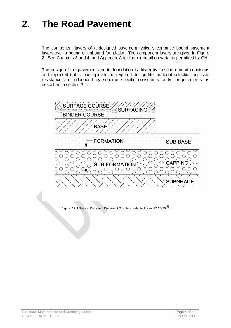
The component layers of a designed pavement typically comprise bound pavement layers over a bound or unbound foundation. The component layers are given in Figure 2.. See Chapters 3 and 4, and Appendix A for further detail on variants permitted by GH.
The design of the pavement and its foundation is driven by existing ground conditions and expected traffic loading over the required design life; material selection and skid resistance are influenced by scheme specific constraints and/or requirements as described in section 3.2.
Figure 2.2 A Typical Designed Pavement Structure (adapted from HD 23/99[4]
)
Structural Maintenance and Surfacing Guide Page 5 of 42 Revision: DRAFT EF V1 Issued 2011
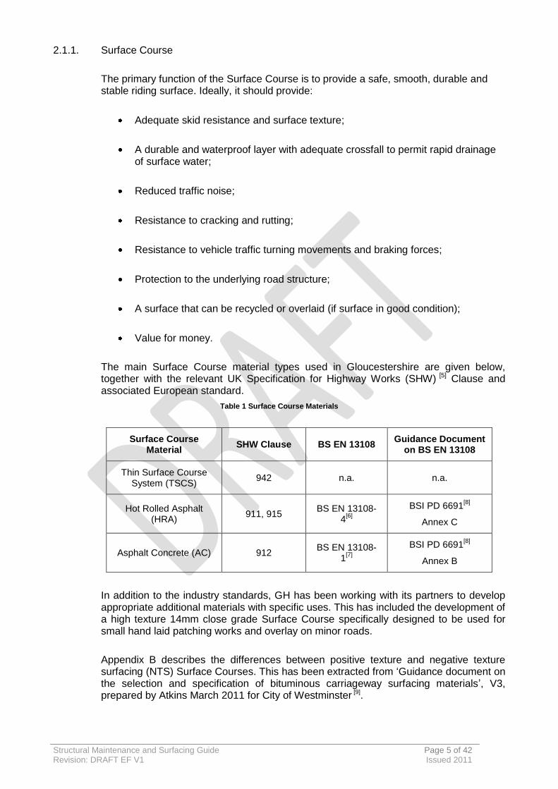
2.1.1. Surface Course
The primary function of the Surface Course is to provide a safe, smooth, durable and stable riding surface. Ideally, it should provide:
Adequate skid resistance and surface texture;
A durable and waterproof layer with adequate crossfall to permit rapid drainage of surface water;
Reduced traffic noise;
Resistance to cracking and rutting;
Resistance to vehicle traffic turning movements and braking forces;
Protection to the underlying road structure;
A surface that can be recycled or overlaid (if surface in good condition);
Value for money.
The main Surface Course material types used in Gloucestershire are given below, together with the relevant UK Specification for Highway Works (SHW) [5] Clause and associated European standard.
Table 1 Surface Course Materials
Surface Course Material
SHW Clause BS EN 13108 Guidance Document
on BS EN 13108
Thin Surface Course System (TSCS)
942 n.a. n.a.
Hot Rolled Asphalt (HRA)
911, 915 BS EN 13108-
4[6]
BSI PD 6691[8]
Annex C
Asphalt Concrete (AC) 912 BS EN 13108-
1[7]
BSI PD 6691[8]
Annex B
In addition to the industry standards, GH has been working with its partners to develop appropriate additional materials with specific uses. This has included the development of a high texture 14mm close grade Surface Course specifically designed to be used for small hand laid patching works and overlay on minor roads.
Appendix B describes the differences between positive texture and negative texture surfacing (NTS) Surface Courses. This has been extracted from ‘Guidance document on the selection and specification of bituminous carriageway surfacing materials’, V3, prepared by Atkins March 2011 for City of Westminster [9].

Structural Maintenance and Surfacing Guide Page 6 of 42 Revision: DRAFT EF V1 Issued 2011
2.1.2. Binder Course
The Binder Course is a structural platform which regulates the top of the underlying base, and helps ensure that surface tolerances are achieved when the Surface Course is laid at a constant thickness. The Binder Course is typically 50-60mm thick using 20mm aggregate. Applied traffic loads are distributed through the Binder Course to the underlying base layer.
The main Binder Course material types used in Gloucestershire are given below, together with the relevant UK SHW [5] Clause and associated European standard.
Table 2 Binder Course Materials
Binder Course Material SHW Clause BS EN 13108 Guidance Document
on BS EN 13108
Hot Rolled Asphalt (HRA)
905 BS EN 13108-
4[6]
BSI PD 6691
[8] Annex C
Asphalt Concrete (AC) 929 BS EN 13108-
1[7]
BSI PD 6691
[8] Annex B
EME2 930 BS EN 13108-
1[7]
BSI PD 6691
[8] Annex B
In addition, GH has developed a SWH [5] Clause 948 B1 cold recycled material using tar-bound planings which can be used on unclassified roads.
2.1.3. Base
The Base is the main structural layer. Stresses induced by traffic loading decrease with depth as they are distributed by the overlying layers; the main function of the base layer is to distribute loads transmitted to it so that the strength capacities of the weaker sub-base and subgrade are not exceeded. Materials for the base layer are commonly the same type as used for Binder Course, except the maximum stone size is 32. The main base material types used in Gloucestershire are given below, together with the relevant UK SHW [5] Clause and associated European standard.
Table 3 Base Materials
Base material SHW Clause BS EN 13108 Guidance Document
on BS EN 13108
Asphalt Concrete (AC) 929 BS EN 13108-
1[7]
BSI PD 6691
[8] Annex B
EME2 930 BS EN 13108-
1[7]
BSI PD 6691
[8] Annex B
Structural Maintenance and Surfacing Guide Page 7 of 42 Revision: DRAFT EF V1 Issued 2011
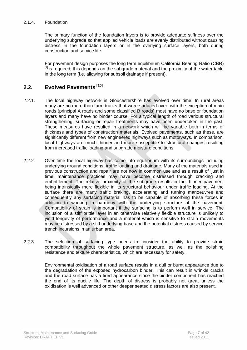
2.1.4. Foundation
The primary function of the foundation layers is to provide adequate stiffness over the underlying subgrade so that applied vehicle loads are evenly distributed without causing distress in the foundation layers or in the overlying surface layers, both during construction and service life.
For pavement design purposes the long term equilibrium California Bearing Ratio (CBR)
[9] is required; this depends on the subgrade material and the proximity of the water table in the long term (i.e. allowing for subsoil drainage if present).
2.2. Evolved Pavements [10]
2.2.1. The local highway network in Gloucestershire has evolved over time. In rural areas many are no more than farm tracks that were surfaced over, with the exception of main roads (principal A roads and some classified B roads) most have no base or foundation layers and many have no binder course. For a typical length of road various structural strengthening, surfacing or repair treatments may have been undertaken in the past. These measures have resulted in a network which will be variable both in terms of thickness and types of construction materials. Evolved pavements, such as these, are significantly different from new engineered highways such as motorways. In comparison, local highways are much thinner and more susceptible to structural changes resulting from increased traffic loading and subgrade moisture conditions.
2.2.2. Over time the local highway has come into equilibrium with its surroundings including underlying ground conditions, traffic loading and drainage. Many of the materials used in previous construction and repair are not now in common use and as a result of ‘just in time’ maintenance practices may have become distressed through cracking and embrittlement. The relative proximity of the subgrade results in the thinner pavement being intrinsically more flexible in its structural behaviour under traffic loading. At the surface there are many traffic braking, accelerating and turning manoeuvres and consequently any surfacing material has to be capable of absorbing these forces in addition to working in harmony with the underlying structure of the pavement. Compatibility of strain is important if the surfacing is to perform well in service. The inclusion of a stiff brittle layer in an otherwise relatively flexible structure is unlikely to yield longevity of performance and a material which is sensitive to strain movements may be distressed by a stiff underlying base and the potential distress caused by service trench incursions in an urban area.
2.2.3. The selection of surfacing type needs to consider the ability to provide strain compatibility throughout the whole pavement structure, as well as the polishing resistance and texture characteristics, which are necessary for safety.
Environmental oxidisation of a road surface results in a dull or burnt appearance due to the degradation of the exposed hydrocarbon binder. This can result in wrinkle cracks and the road surface has a tired appearance since the binder component has reached the end of its ductile life. The depth of distress is probably not great unless the oxidisation is well advanced or other deeper seated distress factors are also present.

Structural Maintenance and Surfacing Guide Page 8 of 42 Revision: DRAFT EF V1 Issued 2011
2.3. Pavement Deterioration
2.3.1. Pavements deteriorate as they are subject to vehicle loading and environmental effects. The main factors in pavement deterioration are:
Traffic – the effects of the action of traffic tyres and loads which cause abrasion and stress leading to fatigue failure of the asphalt layers or deformation in the subgrade material or bound layers;
Weather – the ingress of water into the pavement foundation accelerates deterioration, along with alternating freeze/thaw conditions;
Condition of drainage systems – how effective the drainage systems are at getting water off the carriage and reducing water ingress;
Construction of the asset – particularly the construction of the joints in asphalt layers, the construction of the carriageway and the materials used
Utility works – utility or other incursions into the carriageway will result in weakening of the construction and provide opportunities for water ingress and acceleration of deterioration.
The rate of deterioration will differ across the network depending on the relative construction materials, traffic loading etc. and therefore it is a generalisation to come up with a single figure to represent the deterioration of the network. However, national research shows that typically roads deteriorate between 3% and 4% per year.
This deterioration may be addressed with timely maintenance to obviate failure to operational standards and the need for expensive reconstruction. It is therefore appropriate to periodically assess the condition of the road pavement.
Pavement condition can be considered in terms of functional and structural condition.
Functional condition describes the safety, ride quality and visual appearance of the pavement. The parameters used to ascertain the functional condition include:
Skid Resistance (influenced by Surface Course macro and micro texture);
Roughness (longitudinal profile variance);
Rutting (and other permanent deformations such as potholes and edge break)
Cracking.
Structural condition describes the residual life of the pavement and is typically calculated using deflection data. A number of different machines/ approaches can be used to obtain deflection data. However, the principle is consistent across all approaches; the pavement is subject to a known loading (typically an impulse load) and deflection measurements taken at known displacements from the load point. Further detail on defects is included in Appendix C.

Structural Maintenance and Surfacing Guide Page 9 of 42 Revision: DRAFT EF V1 Issued 2011
2.4. Pavement Assessment
Key to choosing an appropriate maintenance treatment is the identification of defects and an understanding of the mode of deterioration. This will inform the appropriate treatment options.
GH undertakes and commissions annual mechanical and visual condition surveys. The resulting data is used to priority assess, estimate optimum treatment repair methods and timings and to produce initial scheme designs. It is also an essential tool for producing prioritised programmes of works.
Scheduled assessment activities include:
Surface Condition Assessment for the National Network of Roads (SCANNER);
Course Visual Inspections (CVI’s);
Detailed Visual Inspections (DVI’s)
Sideways Force Coefficient Routine Investigation Machine (SCRIM).
2.4.1. SCANNER
All classified roads are surveyed by SCANNER vehicles, which is a mechanical survey using laser and video to categorise and record carriageway defects. The defect scores for each 10m section of road are then amalgamated giving a Road Condition Index value. The Road Condition Index summarises each 10m section as being ‘RED’ (requiring maintenance), ‘AMBER’ (likely to require maintenance soon) or ‘GREEN’ (not requiring maintenance). The survey vehicles are accredited by the Department for Transport and are used by all local authorities to ascertain road condition.
The Road Condition Index scores can be mapped which assists engineers in the selection of sections of road that need to be investigated further for potential structural maintenance schemes. GH carries out SCANNER surveys on about 50% of the classified road network annually.
Figure 2.1 SCANNER Machine [11]

Structural Maintenance and Surfacing Guide Page 10 of 42 Revision: DRAFT EF V1 Issued 2011
2.4.2. Visual Inspection
In addition, GH carries out CVI and the DVI surveys with accredited inspectors trained to record highway defects. Visual inspection survey results not only give an indication of the overall condition of the different networks, but more importantly, they provide defect information and assist in determining proposed treatment types to assist with the planning of future maintenance. CVI survey results also provide the data necessary to report on the unclassified road condition best value performance indicator.
The visual condition surveys are undertaken in accord with the United Kingdom Pavement Management System (UKPMS). The UKPMS Visual Inspection Manual [12]
explains how surveys should be carried out, what should be looked for and how defects should be recorded. GH carry out CVI’s on about 33% of the unclassified road network annually.
2.4.3. SCRIM
The maintenance of adequate levels of skidding resistance on running surfaces is an important aspect of highway maintenance, and one that contributes significantly to safety. Annual surveys are undertaken to assess skid resistance on the county roads that carry the most traffic. SCRIM is the primary method of measuring skidding resistance of the road surface. These surveys provide data, which combined with wet skidding accident data and information about road layout and geometry helps engineers to identify areas of concern.
The friction or skidding resistance required at a site is related to the type and nature of the road and the number of commercial vehicles using the road. Higher skidding resistance is required on bends, downhill gradients and approaches to junctions and pedestrian crossings, whereas straight, level roads in rural areas with no junctions and good visibility do not require as much skidding resistance.
The GH Skid Resistance Policy [13] defines survey frequencies and skid resistance standards. Appendix D includes the relevant extracts for maintenance design purposes.
Figures 2.2 SCRIM Machine [13]

Structural Maintenance and Surfacing Guide Page 11 of 42 Revision: DRAFT EF V1 Issued 2011
2.5. Further Pavement Assessment
Local roads do not typically require the same degree of design input for maintenance as motorway and trunk roads. Although many of the processes are similar, designing a structural maintenance scheme for a local road does not typically involve extensive and costly investigations of pavement layers. See Appendix E for GH Inspection Policy for Tar in Surfacing.
However, further assessment may be undertaken for road sections identified as being defective through the scheduled assessments in certain instances to determine performance, composition or subgrade parameters. Consideration should also be given to other highway features such as drainage which may contribute to pavement deterioration. See Appendix F for further details of testing which may be specified.
Structural Maintenance and Surfacing Guide Page 12 of 42 Revision: DRAFT EF V1 Issued 2011
3. Maintenance
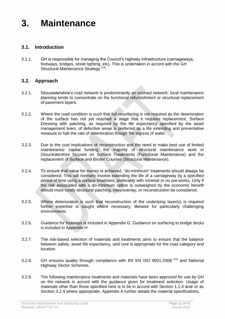
3.1. Introduction
3.1.1. GH is responsible for managing the Council’s highway infrastructure (carriageways, footways, bridges, street lighting, etc). This is undertaken in accord with the GH Structural Maintenance Strategy [14].
3.2. Approach
3.2.1. Gloucestershire’s road network is predominantly an evolved network; local maintenance planning tends to concentrate on the functional refurbishment or structural replacement of pavement layers.
3.2.2. Where the road condition is such that full resurfacing is not required as the deterioration of the surface has not yet reached a stage that it requires replacement, Surface Dressing with patching, as required by the life expectancy specified by the asset management team, of defective areas is preferred as a life extending and preventative measure to halt the rate of deterioration though the ingress of water.
3.2.3. Due to the cost implications of reconstruction and the need to make best use of limited maintenance capital funding, the majority of structural maintenance work in Gloucestershire focuses on Surface Treatments (Functional Maintenance) and the replacement of Surface and Binder Courses (Structural Maintenance).
3.2.4. To ensure that value for money is achieved, “do-minimum” treatments should always be considered. This will normally involve extending the life of a carriageway by a specified period of time using a surface treatment, preferably with minimal or no pre-works. Only if the risk associated with a do-minimum option is outweighed by the economic benefit should more costly structural patching, inlay/overlay, or reconstruction be considered.
3.2.5. Where deterioration is such that reconstruction of the underlying layer(s) is required further expertise is sought where necessary, likewise for particularly challenging environments.
3.2.6. Guidance for footways is included in Appendix G. Guidance on surfacing to bridge decks is included in Appendix H
3.2.7. The risk-based selection of materials and treatments aims to ensure that the balance between safety, asset life expectancy, and cost is appropriate for the road category and location.
3.2.8. GH ensures quality through compliance with BS EN ISO 9001:2008 [15] and National Highway Sector Schemes.
3.2.9. The following maintenance treatments and materials have been approved for use by GH on the network in accord with the guidance given for treatment selection. Usage of materials other than those specified here is to be in accord with Section 1.1.4 and/ or as Section 3.2.4 where appropriate. Appendix A further details the material specifications.
Structural Maintenance and Surfacing Guide Page 13 of 42 Revision: DRAFT EF V1 Issued 2011
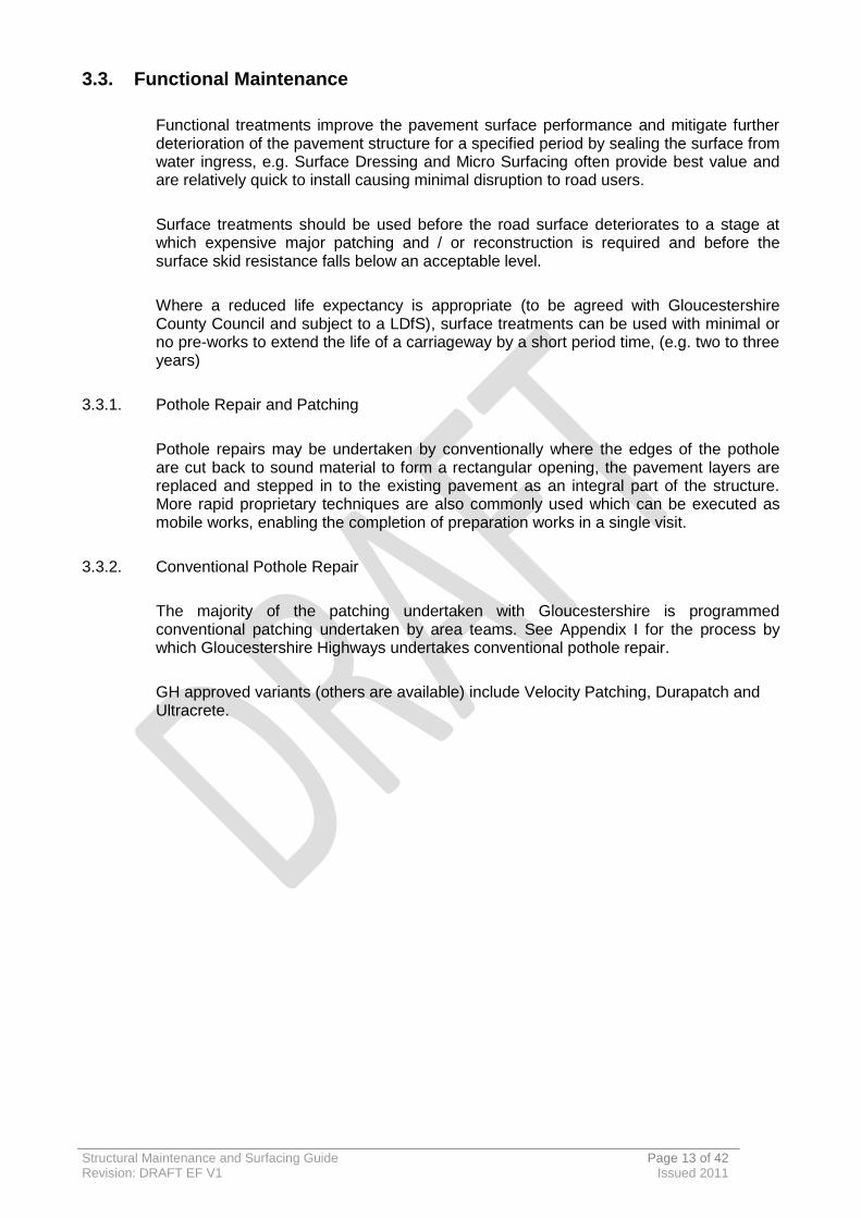
3.3. Functional Maintenance
Functional treatments improve the pavement surface performance and mitigate further deterioration of the pavement structure for a specified period by sealing the surface from water ingress, e.g. Surface Dressing and Micro Surfacing often provide best value and are relatively quick to install causing minimal disruption to road users.
Surface treatments should be used before the road surface deteriorates to a stage at which expensive major patching and / or reconstruction is required and before the surface skid resistance falls below an acceptable level.
Where a reduced life expectancy is appropriate (to be agreed with Gloucestershire County Council and subject to a LDfS), surface treatments can be used with minimal or no pre-works to extend the life of a carriageway by a short period time, (e.g. two to three years)
3.3.1. Pothole Repair and Patching
Pothole repairs may be undertaken by conventionally where the edges of the pothole are cut back to sound material to form a rectangular opening, the pavement layers are replaced and stepped in to the existing pavement as an integral part of the structure. More rapid proprietary techniques are also commonly used which can be executed as mobile works, enabling the completion of preparation works in a single visit.
3.3.2. Conventional Pothole Repair
The majority of the patching undertaken with Gloucestershire is programmed conventional patching undertaken by area teams. See Appendix I for the process by which Gloucestershire Highways undertakes conventional pothole repair.
GH approved variants (others are available) include Velocity Patching, Durapatch and Ultracrete.

Structural Maintenance and Surfacing Guide Page 14 of 42 Revision: DRAFT EF V1 Issued 2011
Velocity Patching (Jetpatch) [26]
Figure 3.1 Jetpatch Machine [16]
This rapid patching technique using a purpose built machine is suitable for use on rural and urban roads. It is typically undertaken prior to Surface Dressing works. It is a 3 stage process:
1. High velocity air is used to remove all dust and debris;
2. Bitumen emulsion bond-coat is forced deep into every crack and crevice to improve the adhesion of the bond coat while at the same time sealing the repair and the road base from further water damage; and
3. Bitumen emulsion and an appropriate aggregate are mixed, then immediately compacted into the void using high velocity. The new material is keyed into the existing surface with superior compaction, without causing further damage to the road base as with conventional methods.
Figure 3.2 Jetpatch Process [16]
GH primarily uses Jetpatch for pre-Surface Dressing pothole repair for potholes of 30mm depth or less. A completed repair may be trafficked immediately.
Figure 3.3 Jetpatch Operation
Structural Maintenance and Surfacing Guide Page 15 of 42 Revision: DRAFT EF V1 Issued 2011
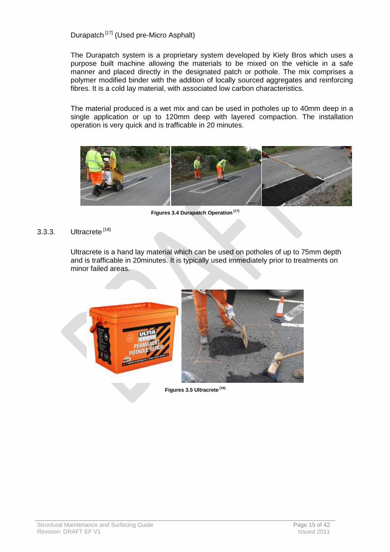
Durapatch [17] (Used pre-Micro Asphalt)
The Durapatch system is a proprietary system developed by Kiely Bros which uses a purpose built machine allowing the materials to be mixed on the vehicle in a safe manner and placed directly in the designated patch or pothole. The mix comprises a polymer modified binder with the addition of locally sourced aggregates and reinforcing fibres. It is a cold lay material, with associated low carbon characteristics.
The material produced is a wet mix and can be used in potholes up to 40mm deep in a single application or up to 120mm deep with layered compaction. The installation operation is very quick and is trafficable in 20 minutes.
Figures 3.4 Durapatch Operation [17]
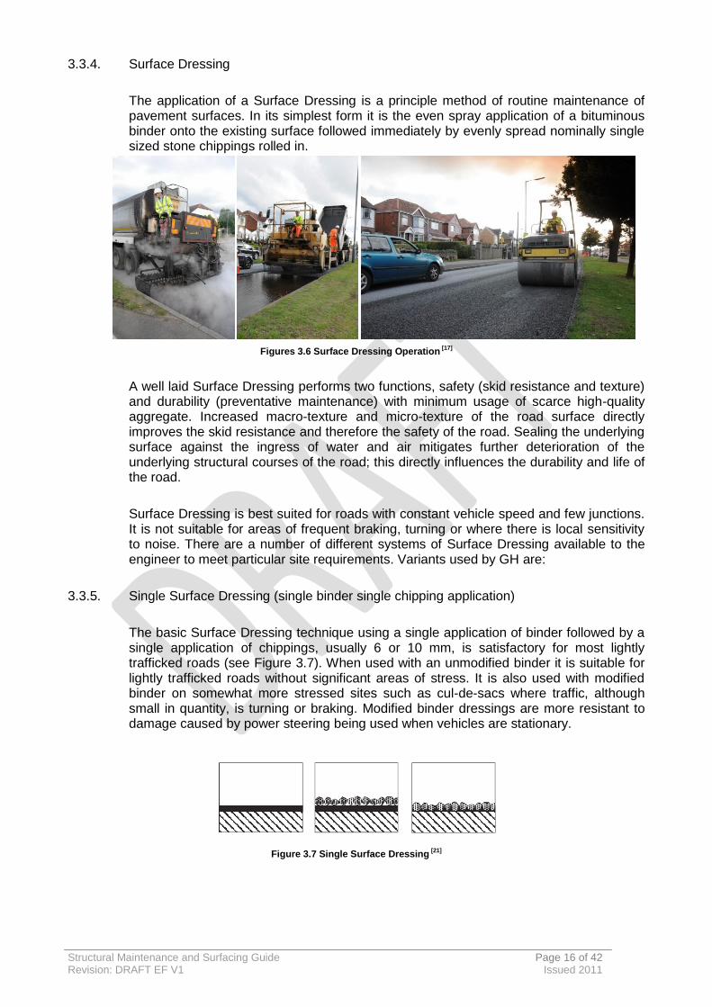
3.3.3. Ultracrete [18]
Ultracrete is a hand lay material which can be used on potholes of up to 75mm depth and is trafficable in 20minutes. It is typically used immediately prior to treatments on minor failed areas.
Figures 3.5 Ultracrete
[18]
Structural Maintenance and Surfacing Guide Page 16 of 42 Revision: DRAFT EF V1 Issued 2011
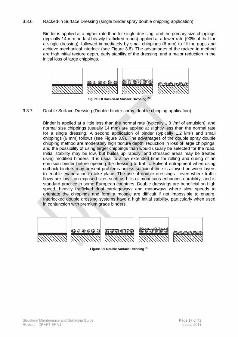
3.3.4. Surface Dressing
The application of a Surface Dressing is a principle method of routine maintenance of pavement surfaces. In its simplest form it is the even spray application of a bituminous binder onto the existing surface followed immediately by evenly spread nominally single sized stone chippings rolled in.
Figures 3.6 Surface Dressing Operation [17]
A well laid Surface Dressing performs two functions, safety (skid resistance and texture) and durability (preventative maintenance) with minimum usage of scarce high-quality aggregate. Increased macro-texture and micro-texture of the road surface directly improves the skid resistance and therefore the safety of the road. Sealing the underlying surface against the ingress of water and air mitigates further deterioration of the underlying structural courses of the road; this directly influences the durability and life of the road.
Surface Dressing is best suited for roads with constant vehicle speed and few junctions. It is not suitable for areas of frequent braking, turning or where there is local sensitivity to noise. There are a number of different systems of Surface Dressing available to the engineer to meet particular site requirements. Variants used by GH are:
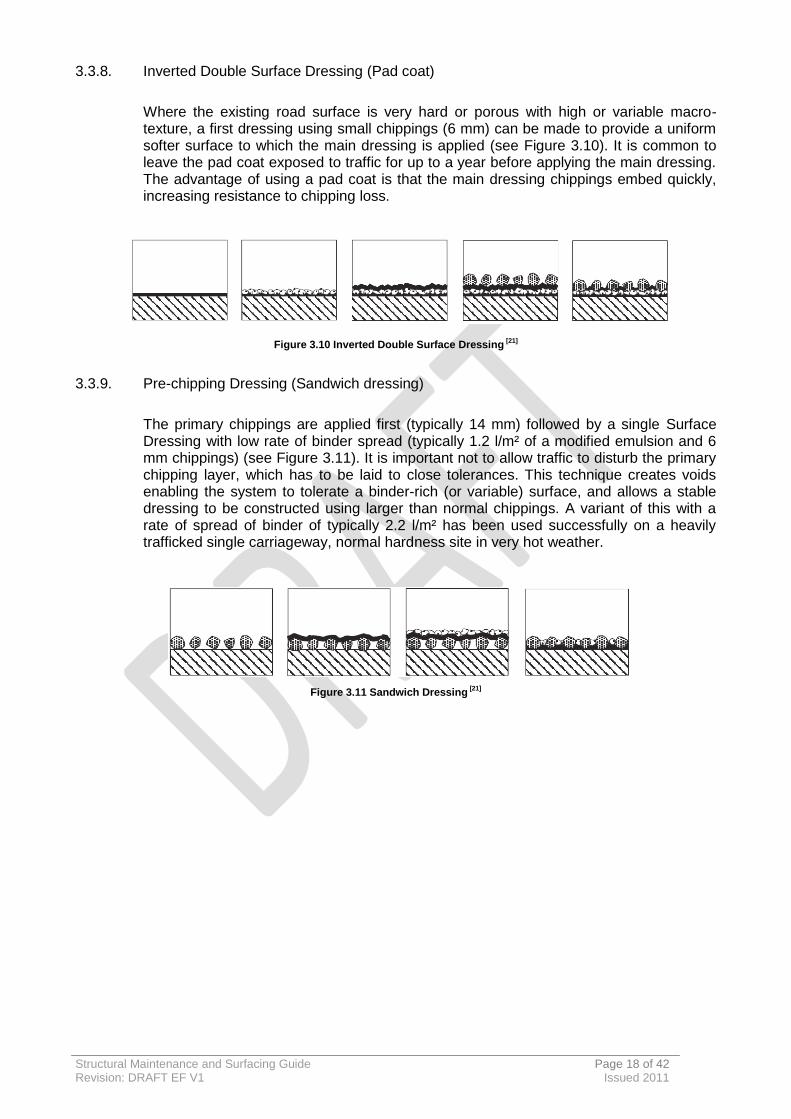
3.3.5. Single Surface Dressing (single binder single chipping application)
The basic Surface Dressing technique using a single application of binder followed by a single application of chippings, usually 6 or 10 mm, is satisfactory for most lightly trafficked roads (see Figure 3.7). When used with an unmodified binder it is suitable for lightly trafficked roads without significant areas of stress. It is also used with modified binder on somewhat more stressed sites such as cul-de-sacs where traffic, although small in quantity, is turning or braking. Modified binder dressings are more resistant to damage caused by power steering being used when vehicles are stationary.
Figure 3.7 Single Surface Dressing [21]
Structural Maintenance and Surfacing Guide Page 17 of 42 Revision: DRAFT EF V1 Issued 2011
3.3.6. Racked-in Surface Dressing (single binder spray double chipping application)
Binder is applied at a higher rate than for single dressing, and the primary size chippings (typically 14 mm on fast heavily trafficked roads) applied at a lower rate (90% of that for a single dressing), followed immediately by small chippings (6 mm) to fill the gaps and achieve mechanical interlock (see Figure 3.8). The advantages of the racked-in method are high initial texture depth, early stability of the dressing, and a major reduction in the initial loss of large chippings.
Figure 3.8 Racked-in Surface Dressing [21]
3.3.7. Double Surface Dressing (Double binder spray, double chipping application)
Binder is applied at a little less than the normal rate (typically 1.3 l/m² of emulsion), and normal size chippings (usually 14 mm) are applied at slightly less than the normal rate for a single dressing. A second application of binder (typically 1.2 l/m²) and small chippings (6 mm) follows (see Figure 3.9). The advantages of the double spray double chipping method are moderately high texture depth, reduction in loss of large chippings, and the possibility of using larger chippings than would usually be selected for the road. Initial stability may be low, but builds up rapidly, and stressed areas may be treated using modified binders. It is usual to allow extended time for rolling and curing of an emulsion binder before opening the dressing to traffic. Solvent entrapment when using cutback binders may present problems unless sufficient time is allowed between layers to enable evaporation to take place. The use of double dressings - even where traffic flows are low - on exposed sites such as hills or mountains enhances durability, and is standard practice in some European countries. Double dressings are beneficial on high speed, heavily trafficked dual carriageways and motorways where slow speeds to orientate the chippings and form a mosaic are difficult if not impossible to ensure. Interlocked double dressing systems have a high initial stability, particularly when used in conjunction with premium grade binders.
Figure 3.9 Double Surface Dressing [21]
Structural Maintenance and Surfacing Guide Page 18 of 42 Revision: DRAFT EF V1 Issued 2011
3.3.8. Inverted Double Surface Dressing (Pad coat)
Where the existing road surface is very hard or porous with high or variable macro-texture, a first dressing using small chippings (6 mm) can be made to provide a uniform softer surface to which the main dressing is applied (see Figure 3.10). It is common to leave the pad coat exposed to traffic for up to a year before applying the main dressing. The advantage of using a pad coat is that the main dressing chippings embed quickly, increasing resistance to chipping loss.
Figure 3.10 Inverted Double Surface Dressing [21]
3.3.9. Pre-chipping Dressing (Sandwich dressing)
The primary chippings are applied first (typically 14 mm) followed by a single Surface Dressing with low rate of binder spread (typically 1.2 l/m² of a modified emulsion and 6 mm chippings) (see Figure 3.11). It is important not to allow traffic to disturb the primary chipping layer, which has to be laid to close tolerances. This technique creates voids enabling the system to tolerate a binder-rich (or variable) surface, and allows a stable dressing to be constructed using larger than normal chippings. A variant of this with a rate of spread of binder of typically 2.2 l/m² has been used successfully on a heavily trafficked single carriageway, normal hardness site in very hot weather.
Figure 3.11 Sandwich Dressing [21]

Structural Maintenance and Surfacing Guide Page 19 of 42 Revision: DRAFT EF V1 Issued 2011
3.3.10. Micro Asphalt
Micro Asphalt is the cold application of thin bituminous Surface Courses incorporating two coats of polymer modified bitumen emulsion and a single application of fine graded aggregate with fillers. Micro Asphalt is GH’s preferred surface treatment in urban environs.
A well laid Micro Asphalt can restore surface condition and reshape/ re-profile the existing road surface by regulating minor deformation whilst restoring surface texture, improving skidding resistance and arresting fretting and ravelling.
Figure 3.12 Micro Asphalt Operation [17]
Structural Maintenance and Surfacing Guide Page 20 of 42 Revision: DRAFT EF V1 Issued 2011
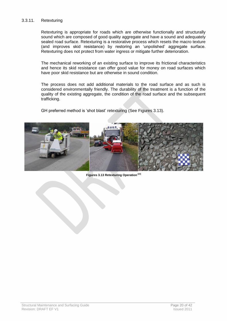
3.3.11. Retexturing
Retexturing is appropriate for roads which are otherwise functionally and structurally sound which are composed of good quality aggregate and have a sound and adequately sealed road surface. Retexturing is a restorative process which resets the macro texture (and improves skid resistance) by restoring an ‘unpolished’ aggregate surface. Retexturing does not protect from water ingress or mitigate further deterioration.
The mechanical reworking of an existing surface to improve its frictional characteristics and hence its skid resistance can offer good value for money on road surfaces which have poor skid resistance but are otherwise in sound condition.
The process does not add additional materials to the road surface and as such is considered environmentally friendly. The durability of the treatment is a function of the quality of the existing aggregate, the condition of the road surface and the subsequent trafficking.
GH preferred method is ‘shot blast’ retexturing (See Figures 3.13).
Figures 3.13 Retexturing Operation
[22]
Structural Maintenance and Surfacing Guide Page 21 of 42 Revision: DRAFT EF V1 Issued 2011
3.4. Structural Maintenance
Structural maintenance generally comprises of deeper and therefore more expensive treatments to restore the condition and value of the asset.
Structural maintenance is generally undertaken following identification of a number of significant defects which cannot be rectified by functional treatments. Activities include:
Structural Patching;
Structural Overlay;
Inlay;
Reconstruction (complete reconstruction of base course and surface layers); and
Haunching (restoration of edge of carriageway).
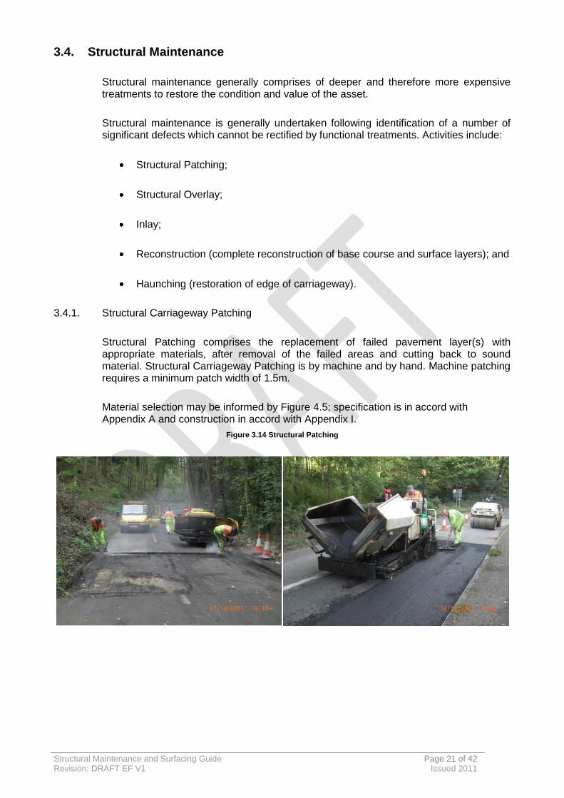
3.4.1. Structural Carriageway Patching
Structural Patching comprises the replacement of failed pavement layer(s) with appropriate materials, after removal of the failed areas and cutting back to sound material. Structural Carriageway Patching is by machine and by hand. Machine patching requires a minimum patch width of 1.5m.
Material selection may be informed by Figure 4.5; specification is in accord with Appendix A and construction in accord with Appendix I.
Figure 3.14 Structural Patching
Structural Maintenance and Surfacing Guide Page 22 of 42 Revision: DRAFT EF V1 Issued 2011
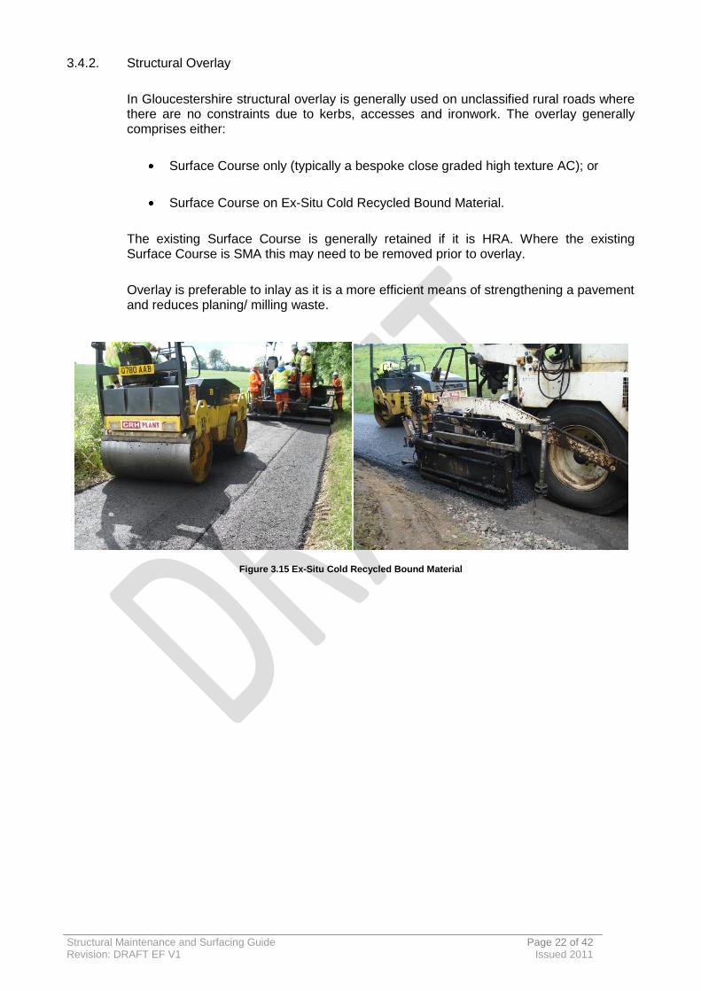
3.4.2. Structural Overlay
In Gloucestershire structural overlay is generally used on unclassified rural roads where there are no constraints due to kerbs, accesses and ironwork. The overlay generally comprises either:
Surface Course only (typically a bespoke close graded high texture AC); or
Surface Course on Ex-Situ Cold Recycled Bound Material.
The existing Surface Course is generally retained if it is HRA. Where the existing Surface Course is SMA this may need to be removed prior to overlay.
Overlay is preferable to inlay as it is a more efficient means of strengthening a pavement and reduces planing/ milling waste.
Figure 3.15 Ex-Situ Cold Recycled Bound Material
Structural Maintenance and Surfacing Guide Page 23 of 42 Revision: DRAFT EF V1 Issued 2011
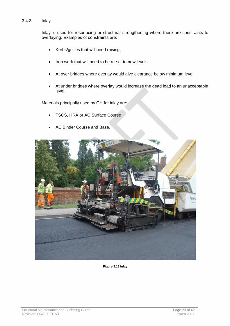
3.4.3. Inlay
Inlay is used for resurfacing or structural strengthening where there are constraints to overlaying. Examples of constraints are:
Kerbs/gullies that will need raising;
Iron work that will need to be re-set to new levels;
At over bridges where overlay would give clearance below minimum level
At under bridges where overlay would increase the dead load to an unacceptable level.
Materials principally used by GH for inlay are:
TSCS, HRA or AC Surface Course
AC Binder Course and Base.
Figure 3.16 Inlay
Structural Maintenance and Surfacing Guide Page 24 of 42 Revision: DRAFT EF V1 Issued 2011
3.4.4. Reconstruction
Reconstruction refers to complete reconstruction of base and surface layers. Where deterioration is such that reconstruction is required further expertise is to be sought so that an informed materials selection may be undertaken accounting for constraints such as available depth and factors which may have attributed to its requirement. Material specification is to be in accord with Appendix A. A LDfS may be used where appropriate/ required.
3.4.5. Haunching
Haunching involves the partial or total reconstruction of the defective carriageway edge structure or the construction of a new section to widen the carriageway. Evolved unclassified roads are often without edge restraint and as such edge breaks can occur when the edge of the carriageway is subjected to stress by heavy vehicles. Haunching assessment and design is to be undertaken in accord with The County Surveyors Society Practical Guide to Haunching [23] such that adequate drainage is maintained. Material specification is to be in accord with Appendix A. A DfS may be used where appropriate/ required.
Structural Maintenance and Surfacing Guide Page 25 of 42 Revision: DRAFT EF V1 Issued 2011
3.5. Materials
3.5.1. Material descriptions have been given in context with BS EN 13018 [20] and are referenced in accord with the GH Surfacing Contract (See Appendix A for the relevant extracts). Section 4.3 gives guidance on material selection.
3.5.2. HRA Surface Course
HRA Surfacing was the material of choice until the middle 1990’s when the poor rutting characteristics, price, and difficulties of laying made it much less popular and hence the HA rescinded it as an option for use on their network, favouring SMA. However, GH has found that many SMA type materials and more recently TSCS materials used on the network over the past 10 years have failed prematurely. Nationally many Local Authorities are moving back towards use of HRA as they are not getting the longevity or performance from SMAs as expected. Life expectancy of SMA’s is between 10 and 15 years, but evidence suggests that many are beginning to show higher rates of pothole defects after year 7. These failings are not fully understood, however, it is considered that there are significant differences between the respective networks. HA roads are typically purpose built, with adequate base and foundation layers, they are also generally better drained and not shaded by trees or hedgerows, and this allows a porous material such as SMA to drain and for water within the negative texture material to evaporate. Additionally, the higher trafficked HA roads would benefit from the hydraulic action of the tyres drawing water from the material to prevent damage from freezing in the winter months.
It is for these reasons that GH have a preferred option of HRA on their network as the material has been used extensively within the county with little sign of failure, typically HRA will last 20 years when laid on a sound substrate.
SMA materials have also become increasingly more difficult to surface dress as during their failure they become brittle as the matrix of the material breaks down, which prevents GH from extracting extra life from the Surface Course.
However HRA has proven to be an extremely good substrate for the laying of Surface Dressings, and although the initial cost of HRA is greater the whole life cost and subsequent ability to dress the material makes it the more cost effective material.
Variants preferred by GH include:
(SC 6) HRA 35/ 14 F surf 40/60 des + 14/20 PCC [8] (High and Medium Speed Traffic)
(SC7) HRA 55/ 10 F surf 40/60[8] (Low Speed Traffic)
3.5.3. HRA Binder Course
HRA Binder Course complements HRA Surface Course. However, within Gloucestershire it is typically only used in particularly challenging environments.
Structural Maintenance and Surfacing Guide Page 26 of 42 Revision: DRAFT EF V1 Issued 2011
HRA Binder Course is impermeable because of its relatively high binder content and is easy to compact due to low air voids. It has similar crack resistance properties to a proprietary crack resistant SMA material. It is therefore likely that it could be used with benefit where a thin overlay is required on a road subject to inundation or which has a wet un-drained sub-base, where a HRA Surface Course has also been specified. For very heavily trafficked roads, and particularly under Thin Surfacing, a lack of rut resistance is likely to be an issue; this can be mitigated by using a polymer-modified binder to achieve the required performance.
The material can be used for regulating within the thickness range for the aggregate size. The surface is not suitable for use by traffic without treatment as it is prone to rutting. A Micro Asphalt or Surface Dressing shall be used if necessary.
Variant preferred by GH:
(BC6 ) HRA 50/ 20 bin 40/ 60 (used in challenging environs).
3.5.4. Stone Mastic Asphalt Surface Course
Variant preferred by GH:
(SC1) SMA 14 surf 40/60 (used for patching existing HRA Surface Courses);
Thin Surface Course Systems (TSCS) to SHW [5] Clause 942
Variants preferred by GH include:
(SC5 ) 14mm (High Speed Traffic)
(SC5 ) 10mm (Medium Speed Traffic).
3.5.5. Asphalt Concrete Surface Course
Variants preferred by GH:
(SC8) AC 10 close surf 100/ 150 (low speed, low traffic, non stressed sites and patching prior to functional treatment);
(SC9) AC 10 close surf 100/ 150 (low speed, low traffic, non-stressed sites, and patching prior to functional treatment);
(SC10) AC 14 close surf 100/ 150 (patching prior to structural treatment);
(SC11) AC 14 close surf 100/ 150 (patching prior to structural treatment)
AC 14 HT (medium and low speed, low traffic, non-stressed sites and overlay).

Structural Maintenance and Surfacing Guide Page 27 of 42 Revision: DRAFT EF V1 Issued 2011
3.5.6. Asphalt Concrete Binder Course
GH predominantly uses Dense Bitumen Macadam (DBM) for structural patching works and High Density Macadam (HDM) for Binder Course inlay. EME2 is available for use in circumstances for which it is enhanced performance brings benefit such as a constrained depth or saturated environs.
Variants preferred by GH:
(BC1) AC 20 dense bin 100/ 150 rec (used for machine patching);
(BC1) AC 20 dense bin 160/ 220 rec (used for hand-laid patching);
(BC2) AC 20 dense bin 100/ 150 rec (used for machine patching);
(BC4) AC 20 HDM bin 40/ 60 des (used for Binder Course inlay);
(BC9) AC 10 EME2 bin/ base 10/20 des (used in challenging environs)
(BC10) AC 10 EME2 bin/ base 15/25 des (used in challenging environs).
3.5.7. Recycled Tar-bound Cold Recycled Binder Course
GH, in partnership with Tarmac, has developed a SHW [5] 900 series compliant cold-recycled Binder Course reusing tar-bound planings for placement on unclassified roads, where permitted following a risk assessment.
This offers carbon, environmental and financial benefits since it mitigates the usage of new materials, effectively using the existing worn-out road material as a linear quarry by recycling planings, negating disposal costs associated with tar-bound material as it is safely encapsulated in the ‘new’ material. See Appendix E for GH Inspection Policy for Tar in Surfacing.
Variant preferred by GH:
(R2) Ex-Situ Cold Recycled Bound Material.
Structural Maintenance and Surfacing Guide Page 28 of 42 Revision: DRAFT EF V1 Issued 2011
3.5.8. Tack coats and bond coats [10]
The efficient transmission of horizontal shear stress is critical to the function of the pavement as a whole.
All pavement layers need to be bonded to the layers above and/or below to assure the maximum structural efficiency of the whole pavement under vertical loading. An effective bond between layers enables the horizontal shear stress between layers to be transmitted. Greatest efficiency is obtained where the horizontal shear strain is small and approaches that in the adjacent asphalt layers. Horizontal shear stresses are small by comparison with the tensile stress in the overall pavement but nonetheless need to be fully transmitted.
Adhesive layer bond is critical in near-surface layers. At points remote from an applied wheel load normal stresses can be tensile and thus no frictional transmission of horizontal shear is possible and total reliance must be placed on the bond coat. Additionally, at shallow depths the horizontal shear forces due to braking, turning, traction on gradients and differential thermal movements are far more concentrated than at greater depths.
Tack coasts are used for HRA materials. Bond Coats are used for NTS materials
The bond coat is essential to ensure the survival of the NTS Surface Course. Fretting, cracking and delamination have been recorded to be the most serious and frequent forms of deterioration of negative texture surfaces and since fretting and delamination are frequently initiated by cracking it follows that a good bond coat is also beneficial in slowing failures due to cracking.
All NTS materials are more permeable than the HRA materials they may have replaced. The ingress of water particularly in evolved pavements is the major cause of deterioration. Substantial bond coats can act as a water barrier beneath negative texture surfaces and assist in extending the life of a pavement but the presence of a horizontal water barrier puts particular importance on the performance of the surface layer when saturated and the ability of any entrapped water to find an escape route into the surface water drainage system.
Road Note 42[24] provides the following advice with regard to tack coats and bond coats:
They should have adequate stability and viscosity to properly penetrate the surface to which it is applied;
They should be applied between all pavement layers (not just the Surface Course and Binder Course)
They should be applied to all vertical surfaces of existing.
GH requires Tack coats and bond coats to be specified in accord with BS 594:2[25] Clause 5.5.

Structural Maintenance and Surfacing Guide Page 29 of 42 Revision: DRAFT EF V1 Issued 2011
4. Treatment Selection
4.1. Introduction
The practical selection of an optimised treatment requires consideration of all factors contributing to the installation and usage of the pavement.
4.2. Considerations [9]
4.2.1. Existing Highway Features
Consideration must be first given to the existing site features and the adequacy or otherwise of the alignment, drainage system and the pavement edge support. GH recommends investigation of drainage systems within structural maintenance schemes, cleaning, root cutting, and making repairs as necessary to ensure that every newly laid surface starts its design life with drainage systems which are working properly and removing surface water from the carriageway surfaces as quickly as possible. Particular care should also be taken to ensure that drainage grips and ditches are cleared.
4.2.2. Defects
The nature and severity of pavement defects drive treatment requirements. In general, structural defects such as severe rutting and cracking require structural treatments and functional defects such as minor rutting, minor cracking and poor texture require functional treatments. See Appendix C for further detail on pavement defects and their remedies.
4.2.3. Site Location
Areas subject to intermittent inundation as a result of the surface profile or river flooding will be resurfaced with HRA as it gives improved safety when saturated and greater durability.
4.2.4. Traffic Speed and Volume
Traffic speed contributes to road noise as further explained in 4.2.7. Traffic loadings, and in particular commercial vehicles, drive deterioration due to the greater forces they exert on the pavement structure. A structural maintenance treatment is preferred for pavements with high traffic speeds and/ or volumes.
4.2.5. Channelized flow
Channelized traffic flows generally occur where the vehicle track width and the traffic lane width are virtually the same. In such circumstances the wheel paths receive concentrated loading. This creates the potential for deformation (i.e. rutting) to occur in the wheel paths.
Structural Maintenance and Surfacing Guide Page 30 of 42 Revision: DRAFT EF V1 Issued 2011
This can be exacerbated by slow moving heavy goods vehicles. Such deformations can:
Adversely affect ride quality (especially for motorcyclists);
Impede surface water flows leading to ponding in the wheel paths which, in turn, presents skid resistance issues in the wet
Cause cracking in the wheel paths which allows the ingress of water into the pavement leading to deterioration.
Normal lane widths do not generally give rise to channelized traffic flows. However, the presence of obstructions (such as traffic calming measures or parked vehicles) can reduce the running width and cause channelized traffic flows. Sharp bends and bus lanes where the running lane width is less than 3m also create channelized traffic flows.
Irrespective of the material choice, for design purposes GH advocates doubling the calculated traffic volumes to account for channelized traffic flow conditions if they occur.
4.2.6. Traffic Management
Chapter 8 of the Traffic Signs Manual [26] requires a lateral safety zone for road works between operatives, plant and active traffic. Laying operations for HRA mixtures traditionally require a wider working area because the application of pre-coated chippings requires the use of a chipping spreading machine which is ‘fed’ with materials from the side by additional plant which works outside of the plan area that is being resurfaced. For many urban roads, and narrow rural roads, safety zone requirements and a lack of available width mean that the side feed loading of chippings cannot be achieved without a road closure. This causes greater network disruption.
NTS mixtures do not require the application of pre-coated chippings and so the required working area is reduced. In many circumstances this means that one carriageway can be resurfaced without closing the other. This has obvious benefits in traffic disruption.
4.2.7. Local sensitivity to noise
The tyre/ surface interaction which occurs as a vehicle passes over a road surface contributes to the overall noise generated by the vehicle (engine and drive train, exhaust and air turbulence). Noise ‘generated’ by this contact can, to a point, be mitigated by road surface characteristics and this forms a key consideration for areas which are sensitive to noise due to their close proximity to conurbations.
Vehicle speed is a significant factor since tyre/ surface noise is generated principally by compression of air within the tyre treads and ‘snap-out’ of the tyre tread rubber as the wheel revolves. At lower speeds the impact of the surface interaction is diminished and vehicle engine, drive train and exhaust contributions are more prevalent.
If the surface texture is of negative type then there is less air compression as the air is ‘free’ to expand into the permeable road surface. Additionally, the evenness and hence reduced rolling resistance on negative texture surfaces does not cause the same degree of tyre wall flexing. Whilst negative texture surfaces do provide a slightly reduced noise tyre/surface profile this needs to be considered against the enhanced durability of positive texture surfaces and their longer service life.

Structural Maintenance and Surfacing Guide Page 31 of 42 Revision: DRAFT EF V1 Issued 2011
4.2.8. Existing Pavement Composition
Careful consideration should be given to the porosity of any new surface material. Water ingress through a more permeable surface than existed previously may lead to distress. Permeability varies but all NTS mixtures are more permeable than HRA mixtures.
4.2.9. High stress sites
High stress sites include carriageway areas subjected to long loading times from buses/heavy goods vehicles and areas where a high proportion of turning movements or braking is likely. In areas where a high proportion of turning movements are predicted, HRA mixtures can deteriorate through the removal (or ‘plucking’) of the pre-coated chippings from the finished surface. The risk of such occurrence is greater during the early life of the Surface Course. The result is a loss of surface texture (which has implications for skid resistance) and an accumulation of loose, dislodged chippings which introduce a variety of additional hazards. NTS mixtures do not require pre-coated chippings and, in a well-designed mix, the aggregate interlock is sufficient to resist the stresses imparted by the tyres of turning vehicles. Benefit is increased by using 10mm size aggregate in preference to 14mm.
4.2.10. Obstructions
The compaction of asphalt materials around ironworks is problematic and often results in a zone of weakness adjacent to the feature (e.g. gulley, manhole cover). Additionally, large items of ironwork can act as a heat sink and thus reduce the mobility of the adjacent hot material during installation by cooling it prematurely. These cooling effects can also prevent the pre-coated chippings from fusing adequately with the mat. Furthermore, compaction plant can create a local irregularity near ironwork which over-stresses the immediate surface surroundings.
HRA mixtures can be ‘hand-laid’ in the localised environs of ironwork and drainage gullies. It is relatively easy to compact and is therefore to be preferred (over NTS mixtures) in most urban situations.
Ironworks present an increased opportunity for water to enter a pavement. All vertical faces of ironworks should be painted with a bituminous material prior to asphalt laying. This should be applied uniformly to the vertical surface to enhance adhesion.
4.2.11. Site Conditions
Road width/ available width is a key consideration since surfacing operations often require the passing and turning of machines. This consideration is more prevalent on the unclassified network and in such instances a mini-paver is used, typically to lay Asphalt Concrete.

Structural Maintenance and Surfacing Guide Page 32 of 42 Revision: DRAFT EF V1 Issued 2011
4.3. Treatment Selection
4.3.1. GH uses a risk based approach to determining the appropriate surface material when considering structural maintenance or resurfacing of the road network. As part of this assessment a practical and common sense decision will be taken with regard to materials that may be more prone to being slippery when wet for equestrian use. Most new road surfaces are not a problem for horses, however, some low texture surfacing materials such as Stone Masticated Asphalts (SMA’s) or other thin surfacing courses may have early life skidding resistance issues that could affect horses. Designers will always take local circumstances into account when selecting surface materials and where equestrian use is prevalent will attempt to use appropriate surface materials.
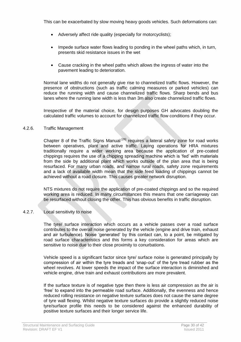
4.3.2. The selection guidance has been developed to assist practitioners through the key decisions involved in the selection of maintenance treatments and materials in the context of Gloucestershire’s network. Table 4.3 summarises the respective performances of functional and structural treatments and Figures 4.3.1 to 4.3.5 present a structured approach to design considerations with suggested treatments/ materials.
4.3.3. Material descriptions have been given in context with BS EN 13018 [6&7] and are referenced in accord with the GH Surfacing Contract. See Appendix A for the relevant extracts.
4.3.4. Texture depth and Polished Stone Values (PSV) in accord with skid resistance policy (Appendix D).
Structural Maintenance and Surfacing Guide Page 33 of 42 Revision: DRAFT EF V1 Issued 2011
Table 4 Treatment Comparison
Notes:
1. Options are ranked in accord with their respective performances/ costs 1 being most favourable.
2. A sound substrate and good workmanship is assumed.
3. Values are to be treated as indicative/ expected only and do constitute a guarantee or warranty.
Parameters
Functional Treatments
Structural Treatments
Close Graded Asphalt Concrete Hot Rolled Asphalt Thin Surfacing Course system
Single Surface
Dressing
Racked-in Surface
Dressing
Double Surface
Dressing
Sandwich Surface
Dressing
Inverted Double Surface
Dressing
Micro Asphalt
AC 10 surf
AC 14 surf
AC 14 surf HT
HRA 35/14
HRA 55/10
HRA 55/14
TSCS 10
TSCS 14
Nominal Thickness (mm)
- - - - - 15 – 20 30 – 40 40 – 50 40 – 50 50 40 45 – 50 40 50
Structural Enhancement
14 13 9 9 9 12 8 7 6 1 3 2 5 4
Rut resistance
14 13 10 10 10 9 5 4 3 8 7 6 2 1
Crack resistance
14 13 10 10 10 9 6 6 6 1 1 1 4 4
Ride improvement
14 13 10 10 10 9 5 4 3 8 7 6 2 1
High texture
5 1 2 2 2 14 9 10 11 6 6 6 12 12
Skidding Resistance 5 1 2 2 2 14 9 10 11 6 6 6 12 12
Typical Noise RSI
14 13 10 12 11 6 3 4 5 7 7 7 1 1
Vehicle Spray
14 13 12 11 10 3 4 4 4 7 7 7 1 1
Risk of early failure
14 13 10 10 10 9 1 1 1 6 6 6 4 4
Durability/ Life
10 11 7 8 9 12 4 4 4 1 1 1 13 14
Additional Structural Life (Years)
- - - - - - 10 - 15 10 - 15 10 15 - 20 15 – 20 15 – 20 6 - 8 6 – 8
Additional Life when in conjunction with new BC (Years)
- - - - - - 15+ 15+ 15+ 20 - 25 20 - 25 20+ 8 – 10+ 8 – 10+
Speed of application
5 4 1 2 3 6 7 7 7 12 12 12 10 11
Cost (m
2)
1 2 3 4 5 6 7 8 9 14 10 11 12 13
Structural Maintenance and Surfacing Guide Page 34 of 42 Revision: DRAFT EF V1 Issued 2011
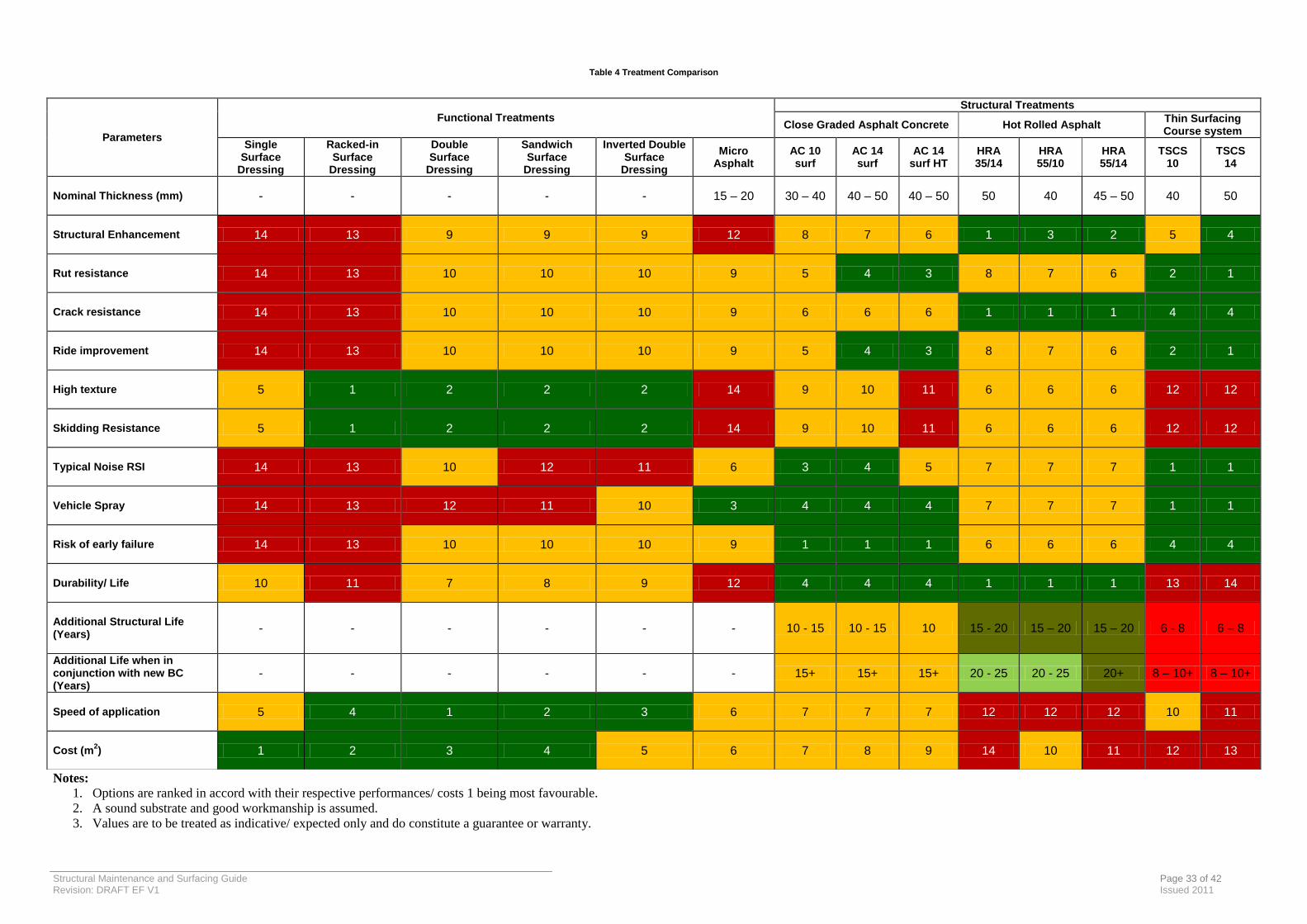
Figure 4.1 Maintenance Selection Guidance
Functional Treatment Required
Figure 4.4 Figure 4.2 Figure 4.3
Visual Survey and Condition
Assessment
Figure 4.6
Patching (If required)
Figure 4.5
Structural Treatment
Surface Dressing (If required)

Structural Maintenance and Surfacing Guide Page 35 Revision: DRAFT EF V1 Issued 2011
Figure 4.2 Visual Survey and Condition Assessment
Visual Inspection
Drainage Effective
Rectify Drainage
Adequate Carriageway Edge Support/ Containment
Undertake Haunching
None or Some Rutting
Extensive Wheel Track Cracking
Extensive Rutting
No Whole Carriageway Cracking
Some Whole Carriageway Cracking
Extensive Whole Carriageway Cracking
Good or Fair Texture
Poor Texture
No Whole Carriageway Cracking
Extensive Whole Carriageway Cracking
Good or Fair Texture
Poor Texture
Poor Texture
Poor Texture
No Treatment Requirement
Retexture or Functional Treatment
No Treatment Requirement
Functional Treatment Required
Functional Treatment Required with Patching
No Treatment Requirement
Functional Treatment Required
No Treatment Requirement
Functional Treatment Required with Patching
Structural Treatment Required
Structural Treatment Required
Structural Treatment Required
Good or Fair Texture
No Wheel Track Cracking
Some Wheel Track Cracking
Some Whole Carriageway Cracking
Good or Fair Texture
Key:
Yes
No

Structural Maintenance and Surfacing Guide Page 36 of 42 Revision: DRAFT EF V1 Issued 2011
Figure 4.3 Functional Maintenance Treatment Selection Guidance
Low Speed Traffic <30mph
Medium Speed Traffic 40 - 60mph
Heavy and Medium Traffic >250 cv/day
Low Traffic <250 cv/day
Structural Maintenance Treatment Required
Surface Dressing
Structural Maintenance Treatment Required
Highly Noise Sensitive Site
Micro Asphalt
Flood Risk
High Noise Sensitive Site
High Stress Site (Gradient Braking/Turning)
Homogenous Texture Depth
Heavy Traffic >4000 cv/day
Surface Dressing
High Speed Traffic >60mph
High Stress Site (Gradient /Braking/Turning)
Skid Resistance and/or Visual Appearance and/or Light Cracking Are Only Defects
Low and Medium Traffic <4000 cv/day
Minimum Capital Cost
Road Width >2.7m and no adjacent banked verges or structures which would inhibit large rigid vehicles turning in carriageway
SC8 or SC9 (AC 10 close surf 100/150)
Road Width >2.7m and no adjacent banked verges or structures which would inhibit large rigid vehicles turning in carriageway
AC 14 HT (Mini Paver)
Road Width >2.7m and no adjacent banked verges or structures which would inhibit large rigid vehicles turning in carriageway
Homogenous Texture Depth
AC 14 HT (Mini Paver)
Key:
Yes
No
Structural Maintenance and Surfacing Guide Page 37 of 42 Revision: DRAFT EF V1 Issued 2011
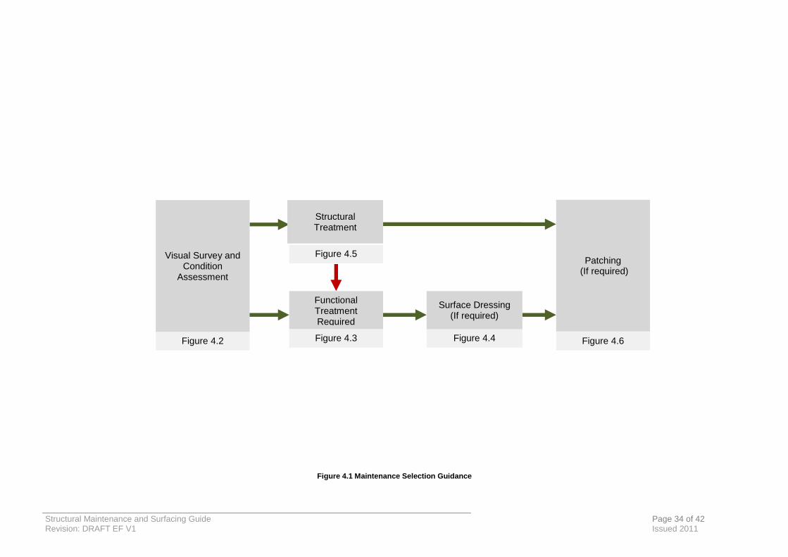
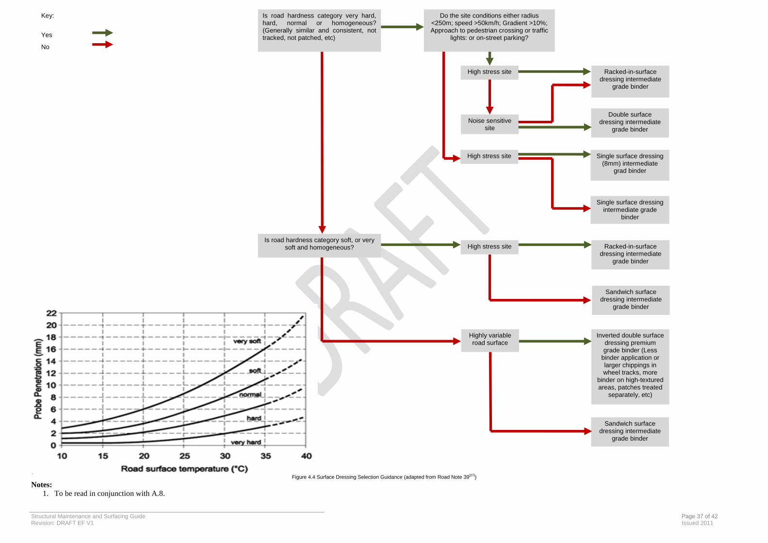
Figure 4.4 Surface Dressing Selection Guidance (adapted from Road Note 39
[27])
Notes: 1. To be read in conjunction with A.8.
Key:
Yes
No
High stress site
Single surface dressing intermediate grade
binder
Sandwich surface dressing intermediate
grade binder
Single surface dressing (8mm) intermediate
grad binder
Is road hardness category soft, or very soft and homogeneous?
Do the site conditions either radius <250m; speed >50km/h; Gradient >10%; Approach to pedestrian crossing or traffic
lights: or on-street parking?
Noise sensitive site
Highly variable road surface
Racked-in-surface dressing intermediate
grade binder
Double surface dressing intermediate
grade binder
Is road hardness category very hard, hard, normal or homogeneous? (Generally similar and consistent, not tracked, not patched, etc)
Racked-in-surface dressing intermediate
grade binder
Inverted double surface dressing premium grade binder (Less
binder application or larger chippings in wheel tracks, more
binder on high-textured areas, patches treated
separately, etc)
Sandwich surface dressing intermediate
grade binder
High stress site
High stress site

Structural Maintenance and Surfacing Guide Page 38 of 42 Revision: DRAFT EF V1 Issued 2011
Figure 4.5 Surface Course Selection Guidance
SC13 (HRA 55/14 F surf 100/150
High Speed Traffic >60mph
Heavy Traffic >4000cv/day
Medium and Low Traffic
<4000cv/day
Medium Speed Traffic 40 –
60mph
Heavy Traffic >4000cv/day
Medium Traffic <250 -
4000cv/day
Low Traffic <250cv/day
Low Speed Traffic <30mph
Noise Sensitive Site
Binder Course Present
SC6 (HRA 35/14 F surf 40/60 des + 14/20 PCC)
SC5 – 14 (Cl 942)
SC5 – 10 (Cl 942) Heavy Traffic >4000cv/day
Low and Medium Traffic <4000 cv/day
Noise Sensitive Site Or Obstructions (Iron Works and Other Features which may
necessitate ‘hand lay’)
Noise Sensitive Site
High Stress Site (Gradient/Braking/Turning)
SC7 (HRA 55/10 F surf 100/150)
Obstructions / Workability (Iron works & other features which may necessitate ‘hand lay’)
AC 14 HT
Functional Treatment
SC7 (HRA 55/10 F surf 100/150)
SC8 or SC9 (AC10 close surf 100/150)
SC5 – 10 (Cl 942)
SC6 (HRA 35/14 F surf 40/60 des + 14/20 PCC)
Noise Sensitive Site
Noise Sensitive Site
SC5 – 10 (Cl 942)
High Stress Site (Gradient/Braking/Turning)
SC6 (HRA 35/14 F surf 40/60 des + 14/20 PCC)
Minimum Capital Cost
Radius <500m/ Roundabout/ Bell mouth
Noise Sensitive Site
Binder Course Present
Key: Yes
Intermediate
No
Flood Risk
Minimum Capital Cost
Structural Maintenance and Surfacing Guide Page 39 of 42 Revision: DRAFT EF V1 Issued 2011
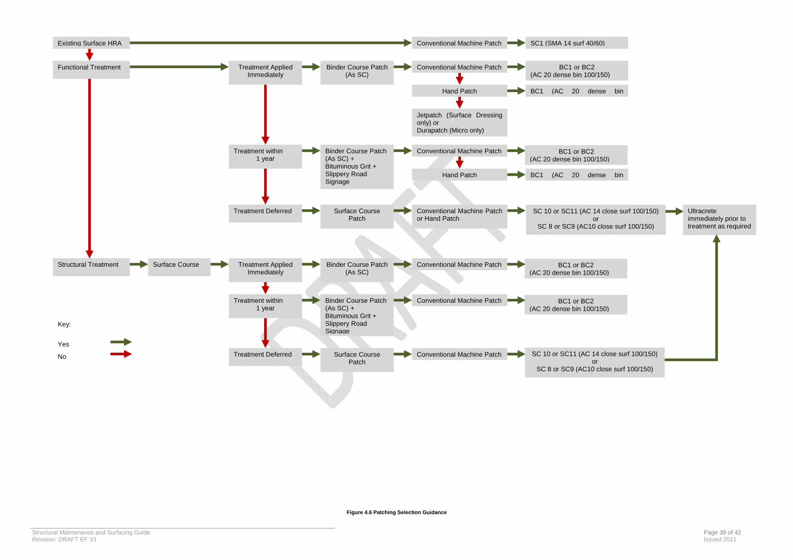
Figure 4.6 Patching Selection Guidance
SC 10 or SC11 (AC 14 close surf 100/150) or
SC 8 or SC9 (AC10 close surf 100/150)
BC1 or BC2 (AC 20 dense bin 100/150)
BC1 or BC2 (AC 20 dense bin 100/150)
BC1 or BC2 (AC 20 dense bin 100/150)
Existing Surface HRA
Functional Treatment
Structural Treatment Surface Course
Treatment Applied Immediately
Treatment within 1 year
Treatment Deferred
Treatment Applied Immediately
Treatment within 1 year
Treatment Deferred
Binder Course Patch (As SC)
Binder Course Patch (As SC) + Bituminous Grit + Slippery Road Signage
Surface Course Patch
BC1 or BC2 (AC 20 dense bin 100/150)
Conventional Machine Patch
Hand Patch
Conventional Machine Patch SC1 (SMA 14 surf 40/60)
Ultracrete immediately prior to treatment as required
Conventional Machine Patch or Hand Patch
Conventional Machine Patch
Hand Patch BC1 (AC 20 dense bin 160/220) (AC 20 dense bin 160/220)
Jetpatch (Surface Dressing only) or Durapatch (Micro only)
Binder Course Patch (As SC)
Binder Course Patch (As SC) + Bituminous Grit + Slippery Road Signage
Surface Course Patch
Conventional Machine Patch
Conventional Machine Patch
Conventional Machine Patch
BC1 (AC 20 dense bin 160/220)
Key:
Yes
No
SC 10 or SC11 (AC 14 close surf 100/150) or
SC 8 or SC9 (AC10 close surf 100/150)
Structural Maintenance and Surfacing Guide Page 40 of 42 Revision: DRAFT EF V1 Issued 2011
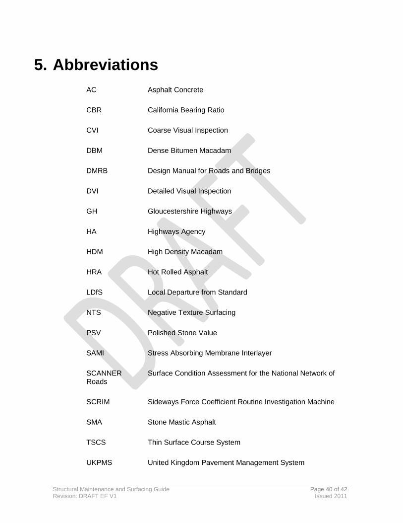
5. Abbreviations
AC Asphalt Concrete
CBR California Bearing Ratio
CVI Coarse Visual Inspection
DBM Dense Bitumen Macadam
DMRB Design Manual for Roads and Bridges
DVI Detailed Visual Inspection
GH Gloucestershire Highways
HA Highways Agency
HDM High Density Macadam
HRA Hot Rolled Asphalt
LDfS Local Departure from Standard
NTS Negative Texture Surfacing
PSV Polished Stone Value
SAMI Stress Absorbing Membrane Interlayer
SCANNER Surface Condition Assessment for the National Network of Roads
SCRIM Sideways Force Coefficient Routine Investigation Machine
SMA Stone Mastic Asphalt
TSCS Thin Surface Course System
UKPMS United Kingdom Pavement Management System

Structural Maintenance and Surfacing Guide Page 41 of 42 Revision: DRAFT EF V1 Issued 2011
6. References 1 ‘Gloucestershire Highways Transport Asset Management Plan’, Gloucestershire
County Council, 2011.
2 ‘Well Maintained Highways’, Roads Liaison Group, 2005.
3 ‘Well Maintained Highways, Code of Practice for Highways Maintenance Management: Complimentary Guidance’, Road Liaison Group, 2011.
4 ‘General Information’, HD 23/99, Design Manual for Roads and Bridges, Volume 7, Section 1, Part 1, TSO, London 1999.
5 ‘Specification for Highway Works’, Manual of Contract Documents for Highway Works, Volume 1, Series 0900, 2008.
6 BS EN 13108-4 Bituminous Mixtures. Material specifications. Hot rolled asphalt, 2004.
7 BS EN 13108-1 Bituminous Mixtures. Material specifications. Asphalt concrete, 2004.
8 BSI PD 6691 Guidance on the use of BS EN 13108 Bituminous mixtures. Material specifications
9 ‘Design of Pavement Foundations’, IAN 73/06, Design Manual for Roads and Bridges, Volume 7, Section 2, Part 2, Wynn Lloyd, 2009.
10 Guidance document on the selection and specification of bituminous carriageway surfacing materials’, V3, Atkins, 2011.
11 WDM Ltd
12 ‘UKPMS Visual Inspection Manual’, UKPMS, 2007.
13 Gloucestershire Highways Skid Resistance Policy, Gloucestershire Highways, 2011.
14 Gloucestershire Highways Structural Maintenance Strategy, Gloucestershire Highways, 2011.
15 BS EN ISO 9001: 2008 Quality Management Systems - Requirements
16 Velocity Patching, 2011.
17 Kiely Brothers Ltd, 2011.
18 Ultracrete, 2011.
19 ‘Surfacing Materials for New and Maintenance Materials’, HD 36/06, Design Manual for Roads and Bridges, Volume 7, Section 5, Part 1, TSO, 1999.
20 BS EN 13108-5 Bituminous Mixtures. Material specifications. Stone Mastic asphalt, 2004.
21 Bituminous Surfacing Materials and Techniques’, HD 37/99, Design Manual for Roads and Bridges, Volume 7, Section 5, Part 2, TSO, 1999.
22 Textureblast Ltd, 2011.
23 ‘The County Surveyors Society Practical Guide to Haunching’,1991

Structural Maintenance and Surfacing Guide Page 42 of 42 Revision: DRAFT EF V1 Issued 2011
24 ‘Best practice guide for durability of asphalt pavements’, Road Note 42, TRL, 2008
25 BS 594-1:2005 Hot rolled asphalt for roads and other paved areas, 2005.
26 Traffic safety measures and signs for road works and temporary situations’, Traffic Signs Manual, Chapter 8, TSO, London, 1997 (now superseded).
27 ‘Design Guide for Road Surface Dressing’, Road Note 39, TRL, 2008
.
Structural Maintenance and Surfacing Guide Page A-1 Revision: DRAFT EF V1 Issued October 2011
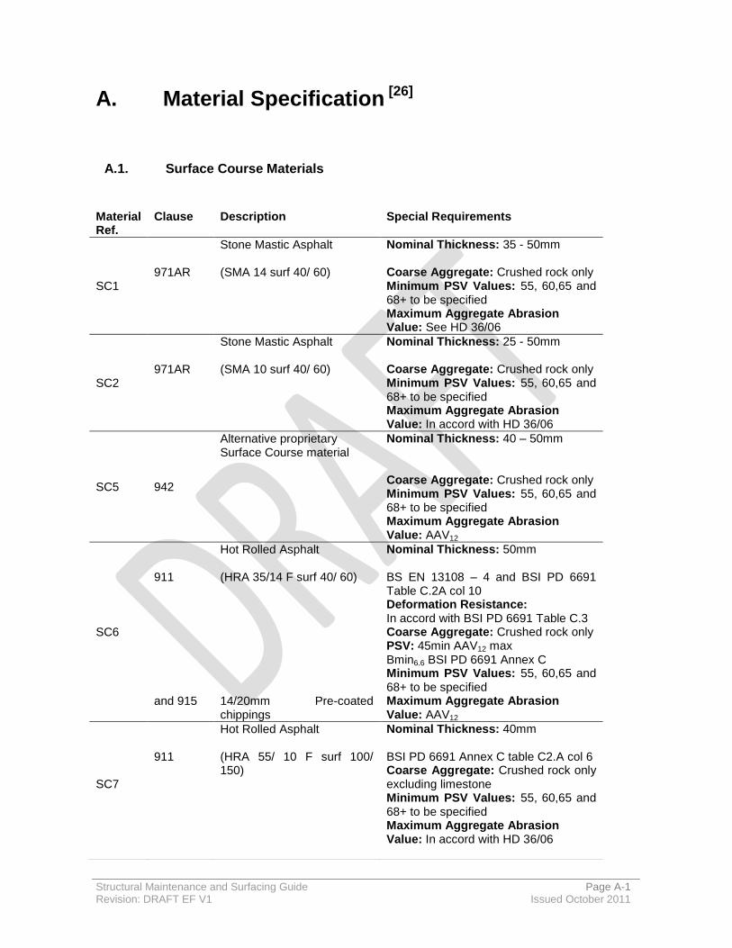
A. Material Specification [26]
A.1. Surface Course Materials
Material Ref.
Clause Description Special Requirements
SC1
971AR
Stone Mastic Asphalt (SMA 14 surf 40/ 60)
Nominal Thickness: 35 - 50mm Coarse Aggregate: Crushed rock only Minimum PSV Values: 55, 60,65 and 68+ to be specified Maximum Aggregate Abrasion Value: See HD 36/06
SC2
971AR
Stone Mastic Asphalt (SMA 10 surf 40/ 60)
Nominal Thickness: 25 - 50mm Coarse Aggregate: Crushed rock only Minimum PSV Values: 55, 60,65 and 68+ to be specified Maximum Aggregate Abrasion Value: In accord with HD 36/06
SC5 942
Alternative proprietary Surface Course material
Nominal Thickness: 40 – 50mm Coarse Aggregate: Crushed rock only Minimum PSV Values: 55, 60,65 and 68+ to be specified Maximum Aggregate Abrasion Value: AAV12
SC6
911 and 915
Hot Rolled Asphalt (HRA 35/14 F surf 40/ 60) 14/20mm Pre-coated chippings
Nominal Thickness: 50mm BS EN 13108 – 4 and BSI PD 6691 Table C.2A col 10 Deformation Resistance: In accord with BSI PD 6691 Table C.3 Coarse Aggregate: Crushed rock only PSV: 45min AAV12 max Bmin6.6 BSI PD 6691 Annex C Minimum PSV Values: 55, 60,65 and 68+ to be specified Maximum Aggregate Abrasion Value: AAV12
SC7
911
Hot Rolled Asphalt (HRA 55/ 10 F surf 100/ 150)
Nominal Thickness: 40mm BSI PD 6691 Annex C table C2.A col 6 Coarse Aggregate: Crushed rock only excluding limestone Minimum PSV Values: 55, 60,65 and 68+ to be specified Maximum Aggregate Abrasion Value: In accord with HD 36/06

Structural Maintenance and Surfacing Guide Page A-2 Revision: DRAFT EF V1 Issued October 2011
Material Ref.
Clause Description Special Requirements
SC8
912
Close Graded Asphalt Concrete (AC 10 close surf 100/ 150)
Nominal Thickness: 30 - 40mm BSI PD 6691 Table B.14 Coarse Aggregate: Crushed rock Minimum PSV Values: 55, 60,65 and 68+ to be specified Maximum Aggregate Abrasion Value: In accord with HD 36/06
SC9
912
Close Graded Asphalt Concrete (AC 10 close surf 100/ 150)
Nominal Thickness: 30 – 40mm BSI PD 6691 Table B.14 Coarse Aggregate: Slag Minimum PSV Values: 55, 60,65 and 68+ to be specified Maximum Aggregate Abrasion Value: In accord with HD 36/06
SC10
912
Close Graded Asphalt Concrete (AC 14 close surf 100/ 150)
Nominal Thickness: 40 – 50mm BSI PD 6691 Table B.14 Coarse Aggregate: Crushed rock Minimum PSV Values: 55, 60,65 and 68+ to be specified Maximum Aggregate Abrasion Value: In accord with HD 36/06
SC11
912
Close Graded Asphalt Concrete (AC 14 close surf 100/ 150)
Nominal Thickness: 40 – 55mm BSI PD 6691 Table B.14 Coarse Aggregate: Slag Minimum PSV Values: 55, 60,65 and 68+ to be specified Maximum Aggregate Abrasion Value: In accord with HD 36/06
SC13
911
Hot Rolled Asphalt (HRA 55/ 14 surf)
Nominal Thickness: 45 – 50mm BSI PD 6691 Annex C table C2.A col 6 Coarse Aggregate: Crushed rock only excluding limestone Minimum PSV Values: 55, 60,65 and 68+ to be specified Maximum Aggregate Abrasion Value: In accord with HD 36/06

Structural Maintenance and Surfacing Guide Page A-3 Revision: DRAFT EF V1 Issued October 2011
A.2. Binder Course Materials
Material Ref.
Clause Description Special Requirements
BC1
906
Asphalt Concrete (AC 20 dense bin 100/ 150 rec) or (AC 20 dense bin 160/ 220 rec)
Nominal Thickness: 50 – 100mm BSI PD 6691 Table B.11 Coarse Aggregate: Crushed rock or crushed gravel only (use of gravel shall reduce penetration grade to 40/ 60 for the same layer thickness) Minimum PSV Value: 60 when surface is to be trafficked.
BC2
906
Asphalt Concrete (AC 20 dense bin 100/ 150 rec)
or (AC 20 dense bin 160/ 220 rec)
Nominal Thickness: 50 – 100mm BSI PD 6691 Table B.11 Coarse Aggregate: Slag Minimum PSV Value:55
BC3
906
Asphalt Concrete (AC 32 dense bin 100/ 150 rec)
Nominal Thickness: 70 -150mm BSI PD 6691 Table B.11 Coarse Aggregate: Crushed rock or crushed gravel only (use of gravel shall reduce penetration grade to 40/ 60 for the same layer thickness)
BC4
929
Asphalt Concrete (AC 20 HDM bin 40/ 60 des)
Nominal Thickness: 50 – 100mm BSI PD 6691 Tables B.6 and B.7 Coarse Aggregate: Crushed rock or crushed gravel only Minimum PSV Value: 60 when surface is to be trafficked (crushed rock only)
BC5
929
Asphalt Concrete (AC 32 HDM bin 40/ 60 des)
Nominal Thickness: 70 -150mm BSI PD 6691 Tables B.6 and B.7 Coarse Aggregate: Crushed rock or crushed gravel only
BC6
905
Hot Rolled Asphalt (HRA 50/ 20 bin 40/ 60)
Nominal Thickness: 45 – 80mm BSI PD 6691 Annex C Table C.1 Coarse Aggregate: Crushed rock or crushed gravel only
BC7
906
Asphalt Concrete (AC 14 dense bin 100/ 150 rec)
Nominal Thickness: BSI PD 6691 Table B.11 Coarse Aggregate: Crushed rock or crushed gravel only (use of gravel shall reduce penetration grade to 40/ 40 for the same layer thickness) Minimum PSV Value: 60 when surface is to be trafficked (crushed rock only)

Structural Maintenance and Surfacing Guide Page A-4 Revision: DRAFT EF V1 Issued October 2011
Material Ref.
Clause Description Special Requirements
BC8
929
Asphalt Concrete (AC 14 HDM bin 40/ 60 des)
Nominal Thickness: BSI PD 6691 Tables B.6 and B.7 Coarse Aggregate: Crushed rock or crushed gravel only Minimum PSV Value: 60 when surface is to be trafficked (crushed rock only)
BC9 930
Asphalt Concrete (AC 10 EME2 bin/ base 10/20 des)
Nominal Thickness: 60-100mm BSI PD 6691 Annex B Table B8 Minimum PSV Value: 60 when surface is to be trafficked
BC10 930
Asphalt Concrete (AC 10 EME2 bin/ base 15/25 des)
Nominal Thickness: 60-100mm Minimum PSV Value: 60 when surface is to be trafficked
BC11 930
Asphalt Concrete (AC 14 EME2 bin/ base 10/20 des)
Nominal Thickness: 70 – 130mm Minimum PSV Value: 60 when surface is to be trafficked
BC12 930
Asphalt Concrete (AC 14 EME2 bin/ base 15/25 des)
Nominal Thickness: 70 – 130mm Minimum PSV Value: 60 when surface is to be trafficked
BC13 930
Asphalt Concrete (AC 20 EME2 bin/ base 10/20 des)
Nominal Thickness: 90 – 150mm Minimum PSV Value: 60 when surface is to be trafficked
BC14 930
Asphalt Concrete (AC 20 EME2 bin/ base 15/25 des)
Nominal Thickness: 90 – 150mm Minimum PSV Value: 60 when surface is to be trafficked
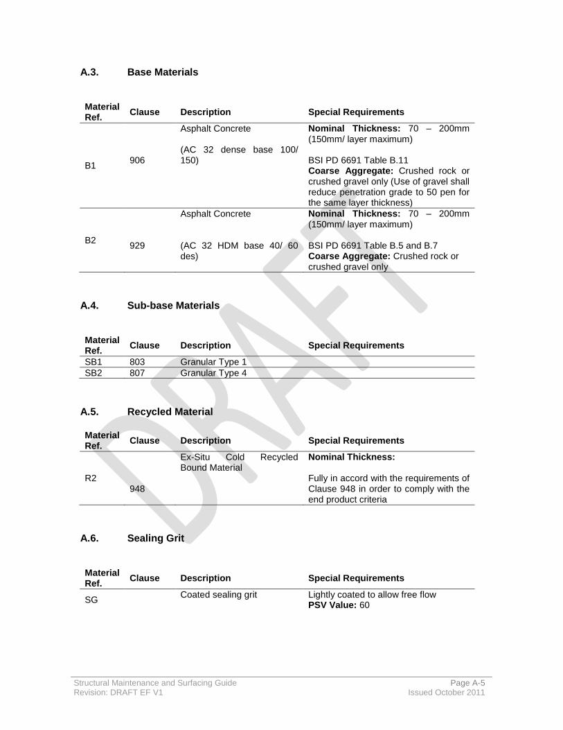
Structural Maintenance and Surfacing Guide Page A-5 Revision: DRAFT EF V1 Issued October 2011
A.3. Base Materials
Material Ref.
Clause Description Special Requirements
B1
906
Asphalt Concrete (AC 32 dense base 100/ 150)
Nominal Thickness: 70 – 200mm (150mm/ layer maximum) BSI PD 6691 Table B.11 Coarse Aggregate: Crushed rock or crushed gravel only (Use of gravel shall reduce penetration grade to 50 pen for the same layer thickness)
B2
929
Asphalt Concrete (AC 32 HDM base 40/ 60 des)
Nominal Thickness: 70 – 200mm (150mm/ layer maximum) BSI PD 6691 Table B.5 and B.7 Coarse Aggregate: Crushed rock or crushed gravel only
A.4. Sub-base Materials
Material Ref.
Clause Description Special Requirements
SB1 803 Granular Type 1
SB2 807 Granular Type 4
A.5. Recycled Material
Material Ref.
Clause Description Special Requirements
R2
948
Ex-Situ Cold Recycled Bound Material
Nominal Thickness: Fully in accord with the requirements of Clause 948 in order to comply with the end product criteria
A.6. Sealing Grit
Material Ref.
Clause Description Special Requirements
SG Coated sealing grit Lightly coated to allow free flow
PSV Value: 60

Structural Maintenance and Surfacing Guide Page A-6 Revision: DRAFT EF V1 Issued October 2011
A.7. Asphalt Reinforcement
Material Ref.
Clause Description Special Requirements
GR1
Asphalt Reinforcing System Approved geosynthetic system, comprising polymer resin coated glass fibre grid with a non woven fabric Tensile strength: 100kN/m²x100kN/m²
GG1
Self Adhesive Asphalt Reinforcing System
Approved geosynthetic system, comprising polymer resin coated glass fibre grid Tensile strength: 100kN/m²x100kN/m²
A.8. Surface Dressing Aggregate Sizing (adapted from Road Note 39[31])
Su
rfa
ce
Dre
ss
ing
Ty
pe
Hardness Category of Road Surface
Very Hard Hard Normal Soft Very Soft
Siz
e o
f C
hip
pin
g (
mm
)
Bin
de
r R
ate
, F
irst L
aye
r (L
/m²)
Bin
de
r R
ate
, S
econ
d L
aye
r (L
/m²)
Siz
e o
f C
hip
pin
g (
mm
)
Bin
de
r R
ate
, F
irst L
aye
r (L
/m²)
Bin
de
r R
ate
, S
econ
d L
aye
r (L
/m²)
Siz
e o
f C
hip
pin
g (
mm
)
Bin
de
r R
ate
, F
irst L
aye
r (L
/m²)
Bin
de
r R
ate
, S
econ
d L
aye
r (L
/m²)
Siz
e o
f C
hip
pin
g (
mm
)
Bin
de
r R
ate
, F
irst L
aye
r (L
/m²)
Bin
de
r R
ate
, S
econ
d L
aye
r (L
/m²)
Siz
e o
f C
hip
pin
g (
mm
)
Bin
de
r R
ate
, F
irst L
aye
r (L
/m²)
Bin
de
r R
ate
, S
econ
d L
aye
r (L
/m²)
Single
2.8/ 6.3
1.5 - 2.8/ 6.3
1.5 - 6.3/ 10
1.6 - 6.3/ 10
1.6 - - - -
Racked-in
10&4 10&6
2 - 10&4 10&6
1.9 - 10&4 10&6
1.9 - 10&4 10&6
1.8 - 10&4 10&6
1.6 -
Double & Double Inverted
10&6
1.2 1.2 10&6 1.1 1.2 10&6 1.0 1.1 14&6 10&6
1.0 0.8
1.2 1.1
10&6 0.8 1.1
Sandwich - - - - - - - - - - - - 10&6 1.3
Structural Maintenance and Surfacing Guide Page B-1 Revision: DRAFT EF V1 Issued October 2011
B. Material Types and Performance
Materials can be considered in terms of ‘Matrix Dominated’ and Aggregate Dominated’.
B.1. Matrix Dominated Materials (Hot Rolled Asphalt)
Matrix dominated materials derive their key engineering performance characteristics through the properties of the matrix: The components of the matrix are typically, mineral sand, limestone powder, and petroleum bitumen. Typical binder contents for recipe formulations of low coarse aggregate HRA are in the range 7-8% (by mass of mixture). The inclusion of binder modifiers can impart significant engineering benefit to the properties of the mixture. These modifiers can be either natural or synthetic.
The uniform particle size distribution of both the fine and coarse mineral components means that the mixture is straightforward to handle and compact.
The proportioning of the aggregates within the mixture delivers a gap grading. For Surface Course a typical coarse aggregate context would be 30% or 35%. The coarse aggregate constituents do not play a significant role in performance. This produces voids within the mix which are filled with a matrix of bitumen, sand and filler content.
It is the matrix (rather than the aggregate) which provides the principal performance characteristics, which include:
Impermeability;
Fatigue resistance;
Durability
Workability when installed (which permits hand-laying).
When installed it has a smooth surface and is virtually impermeable to water and air. Pre-coated chippings are superimposed on the surface of low coarse aggregate content matrix dominated materials to provide skid resistance. This produces a positive texture surface that will cause the tyres of vehicles using the surface to deform and flex, generating noise which increases with speed.
A potential drawback is the susceptibility to deformation (rutting) under certain traffic and/or climatic conditions.

Structural Maintenance and Surfacing Guide Page B-2 Revision: DRAFT EF V1 Issued October 2011
B.2. Aggregate Dominated Materials (Negative Texture Surfacing)
The terms ‘thin surfacing’ and ‘stone mastic asphalt’ are sometimes used to describe aggregate dominated materials, however they all belong to the performance family of ‘Negative Texture Surfacing’ (NTS) materials.
A wide array of particle size distribution is possible ranging from quite dense gradations to quite open (single size) particles. Between these two extremes there are a number of options including hybrid – or ‘stone mastic’ variants.
Their essential engineering function of load distribution and resistance to rutting is achieved through mechanical interlock of the aggregate stone.
Binder contents for aggregate dominated mixtures (NTS) are always less than for matrix dominated mixtures (HRA).
As the aggregate gradations are ‘opened’ there is a prospect of binder draining from the aggregate during transit or placement and in these situations it is usual to include a modifier (either cellulose or polymer) to provide a safeguard. The proportion of modification can be quite low and, since the engineering properties of the mixture are dictated primarily by aggregate gradation, the contribution of any modification is principally to resist binder drainage rather than engineering enhancement.
These materials are sensitive to strain movement and will approach failure through cracking and fretting. They are more susceptible to deformation resulting from failures in the lower pavement layers.
They are designed to be installed continuously with a paving machine. They are quicker and easier to lay in comparison to matrix dominated mixtures. However, they do not lend themselves, with ease, for hand installation or placement around ironwork where compaction energy may be more difficult to impart. This is a limitation in an urban environment.
TSCS provide the best combination of:
Safety, from the initial and retained texture depth;
Cracking resistance/ flexibility for weaker roads;
Deformation resistance for heavier trafficked roads
Low tyre noise, which is significant even on 30+mph sites.
A drawback is that they are permeable and susceptible to water ingress.
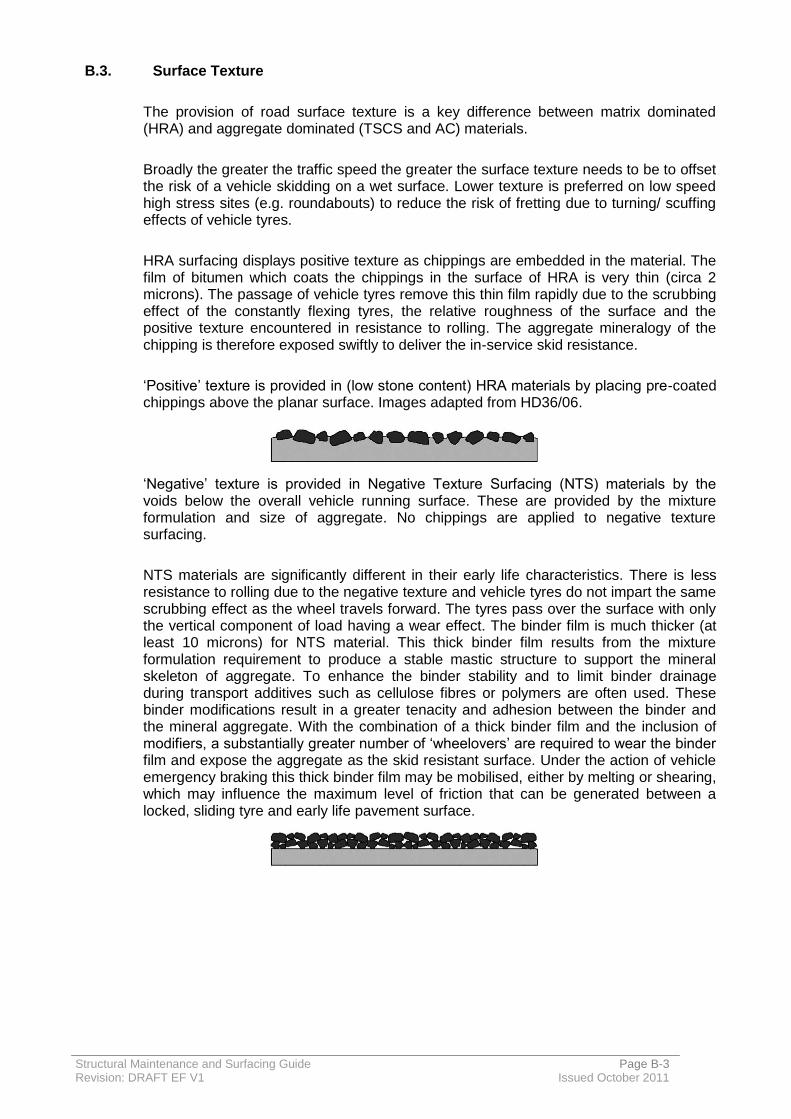
Structural Maintenance and Surfacing Guide Page B-3 Revision: DRAFT EF V1 Issued October 2011
B.3. Surface Texture
The provision of road surface texture is a key difference between matrix dominated (HRA) and aggregate dominated (TSCS and AC) materials.
Broadly the greater the traffic speed the greater the surface texture needs to be to offset the risk of a vehicle skidding on a wet surface. Lower texture is preferred on low speed high stress sites (e.g. roundabouts) to reduce the risk of fretting due to turning/ scuffing effects of vehicle tyres.
HRA surfacing displays positive texture as chippings are embedded in the material. The film of bitumen which coats the chippings in the surface of HRA is very thin (circa 2 microns). The passage of vehicle tyres remove this thin film rapidly due to the scrubbing effect of the constantly flexing tyres, the relative roughness of the surface and the positive texture encountered in resistance to rolling. The aggregate mineralogy of the chipping is therefore exposed swiftly to deliver the in-service skid resistance.
‘Positive’ texture is provided in (low stone content) HRA materials by placing pre-coated chippings above the planar surface. Images adapted from HD36/06.
‘Negative’ texture is provided in Negative Texture Surfacing (NTS) materials by the voids below the overall vehicle running surface. These are provided by the mixture formulation and size of aggregate. No chippings are applied to negative texture surfacing.
NTS materials are significantly different in their early life characteristics. There is less resistance to rolling due to the negative texture and vehicle tyres do not impart the same scrubbing effect as the wheel travels forward. The tyres pass over the surface with only the vertical component of load having a wear effect. The binder film is much thicker (at least 10 microns) for NTS material. This thick binder film results from the mixture formulation requirement to produce a stable mastic structure to support the mineral skeleton of aggregate. To enhance the binder stability and to limit binder drainage during transport additives such as cellulose fibres or polymers are often used. These binder modifications result in a greater tenacity and adhesion between the binder and the mineral aggregate. With the combination of a thick binder film and the inclusion of modifiers, a substantially greater number of ‘wheelovers’ are required to wear the binder film and expose the aggregate as the skid resistant surface. Under the action of vehicle emergency braking this thick binder film may be mobilised, either by melting or shearing, which may influence the maximum level of friction that can be generated between a locked, sliding tyre and early life pavement surface.
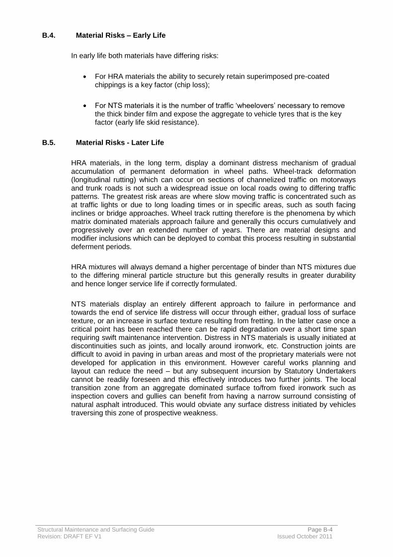
Structural Maintenance and Surfacing Guide Page B-4 Revision: DRAFT EF V1 Issued October 2011
B.4. Material Risks – Early Life
In early life both materials have differing risks:
For HRA materials the ability to securely retain superimposed pre-coated chippings is a key factor (chip loss);
For NTS materials it is the number of traffic ‘wheelovers’ necessary to remove the thick binder film and expose the aggregate to vehicle tyres that is the key factor (early life skid resistance).
B.5. Material Risks - Later Life
HRA materials, in the long term, display a dominant distress mechanism of gradual accumulation of permanent deformation in wheel paths. Wheel-track deformation (longitudinal rutting) which can occur on sections of channelized traffic on motorways and trunk roads is not such a widespread issue on local roads owing to differing traffic patterns. The greatest risk areas are where slow moving traffic is concentrated such as at traffic lights or due to long loading times or in specific areas, such as south facing inclines or bridge approaches. Wheel track rutting therefore is the phenomena by which matrix dominated materials approach failure and generally this occurs cumulatively and progressively over an extended number of years. There are material designs and modifier inclusions which can be deployed to combat this process resulting in substantial deferment periods.
HRA mixtures will always demand a higher percentage of binder than NTS mixtures due to the differing mineral particle structure but this generally results in greater durability and hence longer service life if correctly formulated.
NTS materials display an entirely different approach to failure in performance and towards the end of service life distress will occur through either, gradual loss of surface texture, or an increase in surface texture resulting from fretting. In the latter case once a critical point has been reached there can be rapid degradation over a short time span requiring swift maintenance intervention. Distress in NTS materials is usually initiated at discontinuities such as joints, and locally around ironwork, etc. Construction joints are difficult to avoid in paving in urban areas and most of the proprietary materials were not developed for application in this environment. However careful works planning and layout can reduce the need – but any subsequent incursion by Statutory Undertakers cannot be readily foreseen and this effectively introduces two further joints. The local transition zone from an aggregate dominated surface to/from fixed ironwork such as inspection covers and gullies can benefit from having a narrow surround consisting of natural asphalt introduced. This would obviate any surface distress initiated by vehicles traversing this zone of prospective weakness.
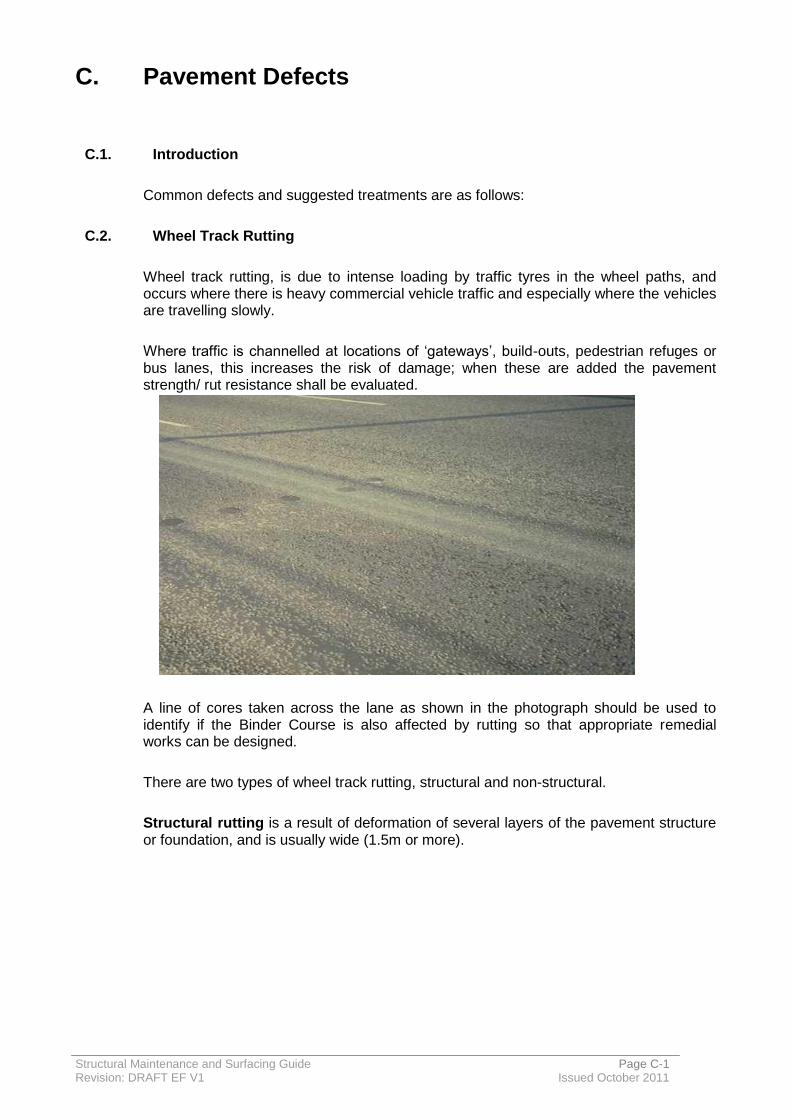
Structural Maintenance and Surfacing Guide Page C-1 Revision: DRAFT EF V1 Issued October 2011
C. Pavement Defects
C.1. Introduction
Common defects and suggested treatments are as follows:
C.2. Wheel Track Rutting
Wheel track rutting, is due to intense loading by traffic tyres in the wheel paths, and occurs where there is heavy commercial vehicle traffic and especially where the vehicles are travelling slowly.
Where traffic is channelled at locations of ‘gateways’, build-outs, pedestrian refuges or bus lanes, this increases the risk of damage; when these are added the pavement strength/ rut resistance shall be evaluated.
A line of cores taken across the lane as shown in the photograph should be used to identify if the Binder Course is also affected by rutting so that appropriate remedial works can be designed.
There are two types of wheel track rutting, structural and non-structural.
Structural rutting is a result of deformation of several layers of the pavement structure or foundation, and is usually wide (1.5m or more).

Structural Maintenance and Surfacing Guide Page C-2 Revision: DRAFT EF V1 Issued October 2011
Non-Structural Rutting (‘plastic’ rutting) is narrower than structural rutting and is mainly due to deformation of the Surface Course and possibly the Binder Course and is generally accompanied by ‘shoving’ of material at the margins of the rut, where material is displaced sideways and upwards by the wheels of heavy vehicles. It is often caused as the surfacing or Binder Course becomes softened by high summer temperatures and is displaced in the wheel paths, with consequent heave to the offside and nearside which may not always be visible. South facing slopes, which are in full sun in the summer months, can have very high surface temperatures that soften the bitumen and increase the risk of rutting.
Both structural and non-structural rutting can yield the same numerical measure of rut depth but the cause must be understood in order to ensure an effective treatment.
In an un-shaded place the summer road surface temperature can be twice the air temperature. This problem will increase with Climate Change predicting an air temperature increase of up to 5ºC which can lead to a consequent surface temperature increase of up to 10 ºC.
Deep ruts [>20mm] can be a safety hazard for motorcyclists. Shallow rutting may be tolerated provided that the texture is maintained on high speed roads and water is not collecting in the ruts.
Deformation is readily measured and data is provided by SCANNER surveys. It is important to determine the depth to which rutting has affected the road layers in order to decide on treatment. This may be carried out by taking a number of interlocking cores across the affected area and measuring the layer thickness.
Materials made with hard or suitable polymer modified binder and/or containing a high percentage of aggregate with good mechanical interlock, such as designed SMA and particularly TSCS, are less prone to deformation than Hot Rolled Asphalt. This has been taken account of in the materials selected.
However further increased durability has been claimed by some suppliers of proprietary products.
Purchasers need to be sure the additional durability benefit delivered by the proprietary product is sufficient to justify the additional cost.
Increased temperatures make the deformation of Binder Courses an increasing probability; it is already clearly evident at many traffic light sites.
Treatment for wheel track rutting
For Surface Course rutting, part removal by milling e.g. 25mm thick and replacement with a 10mm TSCS has proved an effective treatment.
For structural rutting a deeper inlay is normally required to regulate the road levels. The minimum treatment will comprise a Surface Course with regulating Binder Course.
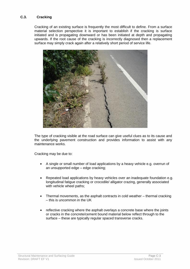
Structural Maintenance and Surfacing Guide Page C-3 Revision: DRAFT EF V1 Issued October 2011
C.3. Cracking
Cracking of an existing surface is frequently the most difficult to define. From a surface material selection perspective it is important to establish if the cracking is surface initiated and is propagating downward or has been initiated at depth and propagating upwards. If the root cause of the cracking is incorrectly diagnosed then a replacement surface may simply crack again after a relatively short period of service life.
The type of cracking visible at the road surface can give useful clues as to its cause and the underlying pavement construction and provides information to assist with any maintenance works.
Cracking may be due to:
A single or small number of load applications by a heavy vehicle e.g. overrun of an unsupported edge – edge cracking;
Repeated load applications by heavy vehicles over an inadequate foundation e.g. longitudinal fatigue cracking or crocodile/ alligator crazing, generally associated with vehicle wheel paths;
Thermal movements, as the asphalt contracts in cold weather – thermal cracking – this is uncommon in the UK
reflective cracking where the asphalt overlays a concrete base where the joints or cracks in the concrete/cement bound material below reflect through to the surface – these are typically regular spaced transverse cracks.
Structural Maintenance and Surfacing Guide Page C-4 Revision: DRAFT EF V1 Issued October 2011
All cracking other than hairline cracking (very narrow width cracking) is detrimental to the structural condition of a road as it reduces the structural strength of the layer and allows water ingress. The water can freeze, expand and thus lead to damage ranging from fretting of the material around the crack to delamination and fragmentation of the pavement layers with, ultimately, complete structural failure.
In severe cases where the cracking extends through the full depth of the bound layers, the water ingress can cause mud-pumping under the action of repeated wheel loading, whereby fine material is removed from the sub-base or sub-grade and pumped to the surface, leading to poor support and instability to the bound road.
New asphalt is a relatively flexible material, the greater the bitumen content the better resistance to cracking. However as the bitumen ages under the effect of air and water, it gets harder, more brittle and more likely to crack.
Materials made with softer binder and/or higher binder content, or a suitable polymer modified binder are generally more durable. However, purchasers need to be sure the benefit delivered by the proprietary product is sufficient to justify the additional cost.
For asphalt roads on a concrete base, whether lean concrete or overlaid concrete slabs, it is very expensive and disruptive to reconstruct, and if at all possible the best and most suitable solution is to leave the concrete in place. A site survey by coring is essential to identify the type of concrete and the thickness of asphalt overlying it as specified in Appendix F.
If cracked concrete is found in the core assessment, trial pits are a useful means of assessing the condition of the concrete surface and the cost of using a Falling Weight Deflectometer to measure slab strength and load transfer between slabs may well be justified for larger schemes.
There are many different types of repair available for cracked roads, ranging from the simplest and cheapest short-term solutions – e.g. sealing the cracks by overbanding – to the most comprehensive, but costly – complete reconstruction. Crack sealing by overbanding is not commonly used by GH due to concerns regarding the skidding risks it may present to motorcyclists; however, proprietary systems are available such as:
Stirling Lloyd Safetrack
Rhino Jointmaster
Suitable treatments for cracking include removal of all or part of the asphalt overlay and replacement with materials that will be more flexible and elastic.
Appropriate Polymer Modified Binders in the asphalt not only improve resistance to cracking but should cracks eventually appear, the material will be less prone to fretting along the crack.
Not all Thin Surface Course Systems are designed to be crack resistant, some have been designed to be very rut resistant or retain their high texture depth under very heavy traffic. Different polymers impart different properties. In general the greater the binder content the more resistant to cracking is the material.

Structural Maintenance and Surfacing Guide Page C-5 Revision: DRAFT EF V1 Issued October 2011
In addition, cracks in lower layers e.g. Cement Bound Bases or trench sides will inevitably reflect through to the surface. The length of time this takes is largely dependent on the thickness of overlay material installed, though this may be extended by the use of a Stress Absorbing Membrane Interlayer SAMI (see below) and a more flexible Binder Course and Surface Course.
Structural Maintenance and Surfacing Guide Page C-6 Revision: DRAFT EF V1 Issued October 2011
Suitable treatments for reflective cracking
Suitable treatments include overbanding and inlay treatments. The life of these treatments is determined by the thickness of the installation.
For more extensive reflective cracking, the use of a Stress Absorbing Membrane Interlayer (SAMI), formed using sprayed systems with and without Geotextiles and Geogrids, is extremely effective at delaying the onset of reflective cracking through a hot mix overlay.
There is no formula to determine when local treatments become uneconomic and treating the whole carriageway is best value. The decision which to use may be dependent upon the condition of the overall road surface and whether it is likely to need replacement in the near future because of other defects such as skid resistance, rutting or trench settlement.
SAMIs available in UK include:
Sprayed polymer modified bitumen membrane system;
Non- woven Geotextile membranes
Geogrids.
Hard data is sparse supporting the benefits of different SAMI options in terms of a longer time before cracking becomes a maintenance issue. This is largely because it is difficult to know whether the system has been effective to prevent a crack reflecting though, or if the crack is simply not moving. Only a percentage of cracks actually move under thermal or traffic stresses. Very large control sections are therefore necessary. In addition the rate of crack propagation is dependent on overlay thickness and material type.
The experience of a number of experienced practitioners suggests that a SAMI can delay a reflective crack by the equivalent of 50mm of standard Asphalt Concrete. However, further evidence is being sought.

Structural Maintenance and Surfacing Guide Page C-7 Revision: DRAFT EF V1 Issued October 2011
Sprayed polymer modified bitumen membrane system with an overlay of fibre reinforced Micro Asphalt to protect the membrane from construction operations and use by light traffic - Flexiplast. This is a specialist proprietary system that requires sufficient area to justify the mobilisation costs. They have been used in the UK for about 10years and there is some evidence of effectiveness at delaying reflective cracking, if there is no differential vertical movement as traffic crosses the crack
Non- woven Geotextile membranes are specialist proprietary systems using Polyfelt PGM 14 Geotextile to protect a sprayed bitumen membrane from construction traffic. They are too slippery for use by normal traffic. They have been used in the UK for about 25 years and there is some evidence of effectiveness at delaying reflective cracking if there is no differential vertical movement as traffic crosses the crack.
1 2
Geogrids, (glass fibre reinforcing meshes) are systems of self adhesive meshes of glass fibre laid on a regulating course or a fine milled surface - Glasgrid. The grid may have an additional sprayed overlay. The grid needs to be slightly tensioned to be effective and permit construction traffic usage. They have been used in the UK for about 15years and there is some evidence of effectiveness at delaying reflective cracking. A Geogrid system is said to be more effective than an un-reinforced SAMI if there is any vertical movement across the crack.
Combination systems of membranes interlaid with grids are also available.
1 Geosynthetics Magazine
2 Maccaferri
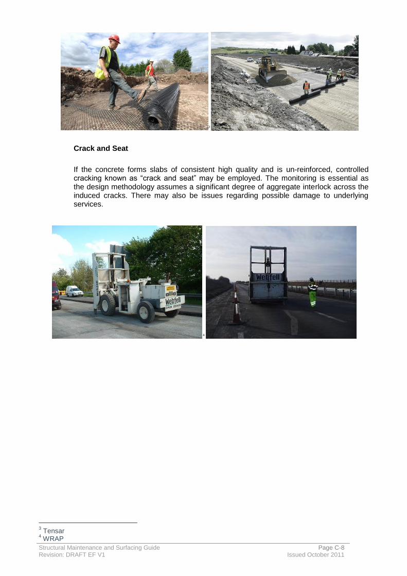
Structural Maintenance and Surfacing Guide Page C-8 Revision: DRAFT EF V1 Issued October 2011
3
Crack and Seat
If the concrete forms slabs of consistent high quality and is un-reinforced, controlled cracking known as “crack and seat” may be employed. The monitoring is essential as the design methodology assumes a significant degree of aggregate interlock across the induced cracks. There may also be issues regarding possible damage to underlying services.
4
3 Tensar
4 WRAP
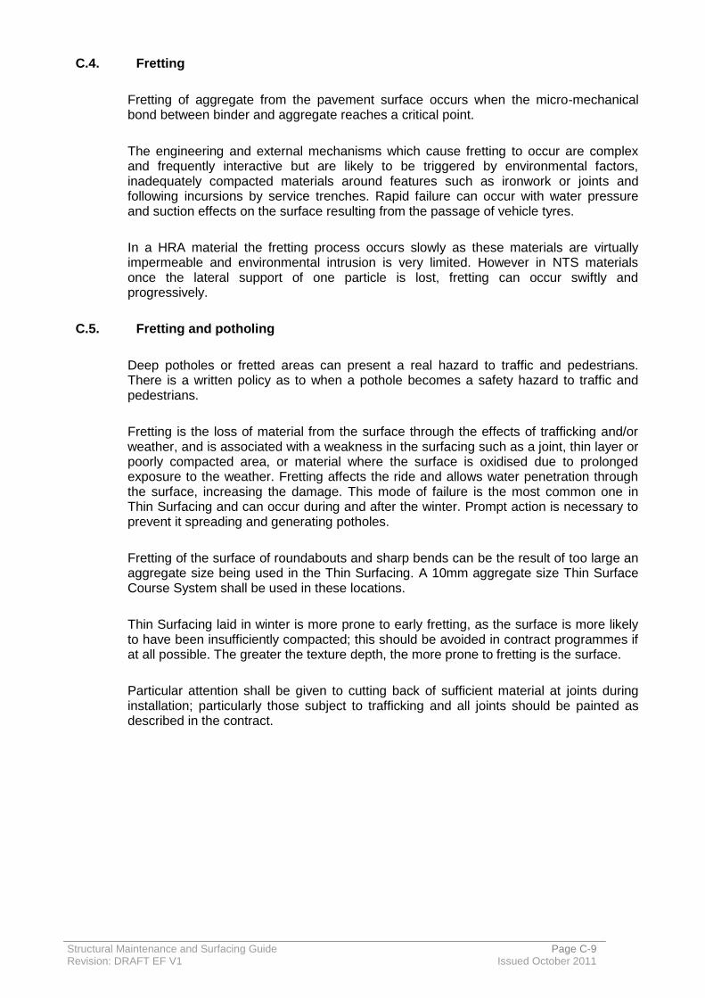
Structural Maintenance and Surfacing Guide Page C-9 Revision: DRAFT EF V1 Issued October 2011
C.4. Fretting
Fretting of aggregate from the pavement surface occurs when the micro-mechanical bond between binder and aggregate reaches a critical point.
The engineering and external mechanisms which cause fretting to occur are complex and frequently interactive but are likely to be triggered by environmental factors, inadequately compacted materials around features such as ironwork or joints and following incursions by service trenches. Rapid failure can occur with water pressure and suction effects on the surface resulting from the passage of vehicle tyres.
In a HRA material the fretting process occurs slowly as these materials are virtually impermeable and environmental intrusion is very limited. However in NTS materials once the lateral support of one particle is lost, fretting can occur swiftly and progressively.
C.5. Fretting and potholing
Deep potholes or fretted areas can present a real hazard to traffic and pedestrians. There is a written policy as to when a pothole becomes a safety hazard to traffic and pedestrians.
Fretting is the loss of material from the surface through the effects of trafficking and/or weather, and is associated with a weakness in the surfacing such as a joint, thin layer or poorly compacted area, or material where the surface is oxidised due to prolonged exposure to the weather. Fretting affects the ride and allows water penetration through the surface, increasing the damage. This mode of failure is the most common one in Thin Surfacing and can occur during and after the winter. Prompt action is necessary to prevent it spreading and generating potholes.
Fretting of the surface of roundabouts and sharp bends can be the result of too large an aggregate size being used in the Thin Surfacing. A 10mm aggregate size Thin Surface Course System shall be used in these locations.
Thin Surfacing laid in winter is more prone to early fretting, as the surface is more likely to have been insufficiently compacted; this should be avoided in contract programmes if at all possible. The greater the texture depth, the more prone to fretting is the surface.
Particular attention shall be given to cutting back of sufficient material at joints during installation; particularly those subject to trafficking and all joints should be painted as described in the contract.
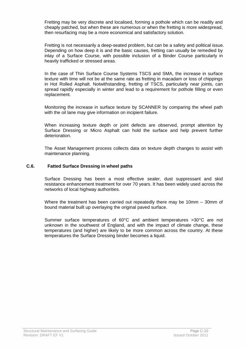
Structural Maintenance and Surfacing Guide Page C-10 Revision: DRAFT EF V1 Issued October 2011
Fretting may be very discrete and localised, forming a pothole which can be readily and cheaply patched, but when these are numerous or when the fretting is more widespread, then resurfacing may be a more economical and satisfactory solution.
Fretting is not necessarily a deep-seated problem, but can be a safety and political issue. Depending on how deep it is and the basic causes, fretting can usually be remedied by inlay of a Surface Course, with possible inclusion of a Binder Course particularly in heavily trafficked or stressed areas.
In the case of Thin Surface Course Systems TSCS and SMA, the increase in surface texture with time will not be at the same rate as fretting in macadam or loss of chippings in Hot Rolled Asphalt. Notwithstanding, fretting of TSCS, particularly near joints, can spread rapidly especially in winter and lead to a requirement for pothole filling or even replacement.
Monitoring the increase in surface texture by SCANNER by comparing the wheel path with the oil lane may give information on incipient failure.
When increasing texture depth or joint defects are observed, prompt attention by Surface Dressing or Micro Asphalt can hold the surface and help prevent further deterioration.
The Asset Management process collects data on texture depth changes to assist with maintenance planning.
C.6. Fatted Surface Dressing in wheel paths
Surface Dressing has been a most effective sealer, dust suppressant and skid resistance enhancement treatment for over 70 years. It has been widely used across the networks of local highway authorities.
Where the treatment has been carried out repeatedly there may be 10mm – 30mm of bound material built up overlaying the original paved surface.
Summer surface temperatures of 60°C and ambient temperatures >30°C are not unknown in the southwest of England, and with the impact of climate change, these temperatures (and higher) are likely to be more common across the country. At these temperatures the Surface Dressing binder becomes a liquid.

Structural Maintenance and Surfacing Guide Page C-11 Revision: DRAFT EF V1 Issued October 2011
Rural traffic loads have increased with the increase in weight of private and commercial vehicles. As a result fatting up of the surface occurs, leading to poor skid resistance in the dry and possibly dangerous levels when wet, pick up of binder on car and cycle tyres and by pedestrians and surface deformation in the wheel tracks which hold water – this may not always be present if the traffic levels are low.
The binder may be bitumen with the addition of a light oil flux, bitumen cut-back with creosote or tar. The last two are no longer used but may exist within the bound layers; they are carcinogenic and treated as hazardous waste. Any volatile materials can be trapped within the overlays by subsequent treatments. The scale of the potential problem is very large with 50,000 km of road at risk in UK. The costs of treatments are not insignificant.
Identification of the problem
The problems will be easy to see by visual inspection, and may be indicated by machine surveys, by SCANNER and SCRIM, by public complaint or from accident records.
Remedial works for fatted Surface Dressing
Remedial works can be categorised into four; remove excess binder from the surface, treat melted layers, cover melted layers, remove soft material and replace with hot mix. Each has strengths and weakness. These are given in the table below.
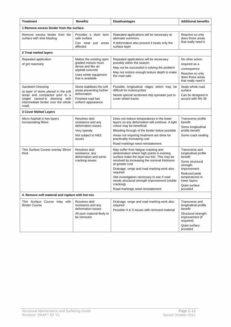
Structural Maintenance and Surfacing Guide Page C-12 Revision: DRAFT EF V1 Issued October 2011
Treatment Benefits Disadvantages Additional benefits
1 Remove excess binder from the surface.
Remove excess binder from the surface with shot blasting
Provides a short term safe surface
Can treat just areas affected
Repeated applications will be necessary at alternate summers.
If deformation also present it treats only the surface layer
Reactive so only does those areas that really need it
2 Treat melted layers
Repeated application
of grit reactively
Makes the existing open graded mixture more dense and like an asphalt concrete
Uses winter equipment that is available
Repeated applications will be necessary possibly within the season.
May not be successful in solving the problem
May not restore enough texture depth to make the road safe.
No other action
required as a
consequence
Reactive so only does those areas that really need it
Sandwich Dressing
(a layer of stone placed in the soft areas and compacted prior to a single/ racked-in dressing with intermediate binder over the whole road)
Stone stabilises the soft areas preventing further deformation
Finished road has uniform appearance
Possible longitudinal ridges which may be difficult for motorcyclists
Needs special sectioned chip spreader just to cover wheel tracks
Seals whole road surface
Can be designed in accord with RN 39
3 Cover Melted Layers
Micro Asphalt in two layers incorporating fibres
Resolves skid resistance and any deformation issues
Very speedy
Not subject to H&S issues
Does not reduce temperatures in the lower layers so any deformation will continue. A light colour may be beneficial
Bleeding through of the binder below possible
Areas not requiring treatment are done for practicality increasing cost
Road markings need reinstatement.
Transverse profile benefit
Some longitudinal profile benefit
Some crack sealing
Thin Surface Course overlay 35mm thick
Resolves skid resistance, any deformation and some cracking issues
May suffer from fatigue cracking and delamination where high points in existing surface make the layer too thin. This may be resolved by increasing the nominal thickness at greater cost
Drainage, verge and road marking work also required
Site investigation necessary to see if road needs structural strength improvement (visible cracking)
Road markings need reinstatement
Transverse and longitudinal profile benefit
Some structural strength improvement
Reduced peak temperatures in lower layers
Quiet surface provided
4. Remove soft material and replace with hot mix
Thin Surface Course inlay with Binder Course
Resolves skid resistance and any deformation issues
All poor material likely to be removed
Drainage, verge and road marking work also required
Possible H & S issues with removed material
Transverse and longitudinal profile benefit
Structural strength improvement (if required)
Quiet surface provided

Structural Maintenance and Surfacing Guide Page D-1 Revision: DRAFT EF V1 Issued October 2011
D. Skid Resistance
D.1. Introduction
GH has taken a risk based approach to PSV specification. The GH Skid Resistance Policy defines the skid resistance policy for Gloucestershire and identifies the practice and procedures adopted by Gloucestershire from the guidance that is currently available and local experience.
D.2. PSV specification
Class A and B roads are design in accord with DMRB guidance (HD 36/06 – Table 3.1).
Table 3.1 provides the PSV requirements for new surface courses on motorways and trunk roads and while this may be appropriate for roads with a hierarchy of 2, 3a and 3b, it would be over specified for minor roads. In table 3.1, the PSV requirement for surfacing aggregate reduces with the reduction in commercial vehicle traffic. Taking this into account and also the fact that roads of this nature do not exist in the trunk road network, PSV values have been modified to reflect the requirements of the lower hierarchy roads in the network.
Historically the county has used locally sourced aggregate with a PSV value of between 60 and 65. Accident analysis concludes that roads of this nature, that were surfaced with this aggregate, do not exhibit accident rates above what is average for a road of this type. It can therefore be assumed that continued use of these materials will provide the public with a safe road surface.
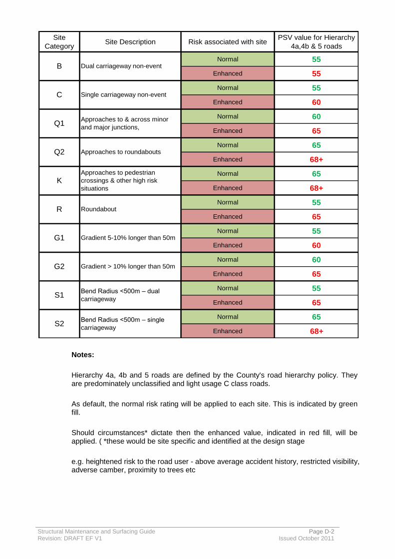
Structural Maintenance and Surfacing Guide Page D-2 Revision: DRAFT EF V1 Issued October 2011
Notes:
Hierarchy 4a, 4b and 5 roads are defined by the County's road hierarchy policy. They are predominately unclassified and light usage C class roads.
As default, the normal risk rating will be applied to each site. This is indicated by green fill.
Should circumstances* dictate then the enhanced value, indicated in red fill, will be applied. ( *these would be site specific and identified at the design stage
e.g. heightened risk to the road user - above average accident history, restricted visibility, adverse camber, proximity to trees etc
Site
CategorySite Description Risk associated with site
PSV value for Hierarchy
4a,4b & 5 roads
Normal 55
Enhanced 55
Normal 55
Enhanced 60
Normal 60
Enhanced 65
Normal 65
Enhanced 68+
Normal 65
Enhanced 68+
Normal 55
Enhanced 65
Normal 55
Enhanced 60
Normal 60
Enhanced 65
Normal 55
Enhanced 65
Normal 65
Enhanced 68+
Q2 Approaches to roundabouts
S2Bend Radius <500m – single
carriageway
G2 Gradient > 10% longer than 50m
S1Bend Radius <500m – dual
carriageway
R Roundabout
G1 Gradient 5-10% longer than 50m
KApproaches to pedestrian
crossings & other high risk
situations
C Single carriageway non-event
Q1Approaches to & across minor
and major junctions,
B Dual carriageway non-event
Structural Maintenance and Surfacing Guide Page D-3 Revision: DRAFT EF V1 Issued October 2011
D.3. Equestrians and Skidding Resistance
As equestrian use in Gloucestershire’s rural areas is very prevalent, GH has adopted the policy of including 3mm quartzite grit in the surface mix whenever thin surfacing materials are used to provide additional skid resistance for horses.
At areas where the road is likely to be used by horses immediately after installation, it is proposed to apply quartzitic grit during construction to enhance initial frictional resistance and facilitate early removal of the surface binder film and so reduce the risk of slipping. This is in accord with County Surveyors Society/ British Horse Society guidance note ENG03/05: Horses and Highway Surfacing. The rate of grit application to be such that macrotexture is not compromised to the cost of other road users.
D.4. Texture
Surface Macrotexture for Surface Course: To Clause 921
Structural Maintenance and Surfacing Guide Page E-1 Revision: DRAFT EF V1 Issued October 2011
E. Inspection Policy for Tar in Surfacing
E.1. Overall Policy Aims
Establish objectives and policy for tar bound materials, managed as part of highway maintenance obligations.
Establish an inspection and testing regime using a risk based approach to minimise the risk of tar bound material being disposed of without it having been classified.
Minimise the financial and ecological impact of tar bound materials by early classification of the material, and design of the scheme to minimise the need for the removal of any hazardous waste.
E.2. Purpose of Tar Investigations
Investigating whether an existing road or footway contains tar at the earliest opportunity will allow time for testing to ascertain whether or not the material is a hazardous waste, the extent of the material and the cost analysis of disposing of the material or seeking an alternative scheme design.
For the purpose of this policy, tar bound material is any material found within the existing construction of a footway or carriageway which contains tar.
E.3. Hazardous Material Classification
The classification of tar bound materials is very complex. Under legislation the material is not classed as being hazardous or non hazardous but is classed as a mirror entry. This means that its classification is based on the levels of the dangerous substances it contains. In coal tar these dangerous substances are referred to as PAHs, polycyclic aromatic hydrocarbons.
PAHs are classed as carcinogenic, meaning that they are either known to cause cancer, or suspected as causing cancer. The limit for any one of the 16 PAHs contained in coal tar products of this nature is no greater than 0.1% for any one.
PAHs are established by having cores that are suspected of containing tar tested at a specialist laboratory. If any of the 16 PAHs are greater than 0.1% then the material should be treated as hazardous waste and sent for further testing (WAC) prior to disposal.
In addition, some PAHs are also classed as being eco toxic, although the threshold level for this is 0.25% they are different in that all the PAHs that are eco toxic are added together to arrive at the total (there are 9 of the 16 PAHs that are eco toxic) and the total must not exceed 0.25%.

Structural Maintenance and Surfacing Guide Page E-2 Revision: DRAFT EF V1 Issued October 2011
E.4. Identification and Testing
The following systems are proposed to be adopted for the identification and testing of materials to ensure that any tar present is classified.
In order to keep a perspective on the quantity and risk imposed by the material and to allow as great a flexibility as possible the systems are divided between major works and minor works.
E.5. Major Works
At the preliminary design phase, where possible, we will have to take steps to identify such materials, primarily tar based road surfacing, and where its removal is essential, to plan for its safe disposal during the design.
Projects where we have identified a need to remove surfacing in excess of 200m2, or the complete removal of the road surface material over a structure we need to confirm the presence of tar based products, unless there is clear evidence to the contrary, through an as built or H&S file etc.
Cores should be taken at random positions, or alternatively by conducting trial holes, unless specific areas are more likely to contain tar. Samples should be taken at maximum of 500m intervals with a minimum of two cores per site. This information can be used to gain knowledge of the road make up, and aid the design process and risk assessment. Cores should be taken in both directions to confirm the construction make up.
The cores are then sprayed with a tar detecting paint known as PAK Marker, where any layers within the core that may contain tar bound materials will react with the PAK marker and indicate a possible tar presence ( the white paint will show a brown colour where tar is detected).This will be indicated on the core logs.
The layers that are affected are noted, and a decision is made as to which layers are to be further tested to confirm the percentage of PAHs and clarify the nature of the material.
The cores are then sent to the laboratory for testing to clarify whether the layers detected by the PAK marker are hazardous or non hazardous. This will be indicated by the PAH contents of the layers shown in the results, where concentrations greater than 0.1% are classified as hazardous.
Once the results are returned the designer can try to mitigate the hazardous layers by altering the design, i.e. overlays or reduced thickness and varying material types. Where it is not possible to mitigate the areas of hazardous material, the material can either be planed out and recycled, or taken to a licensed hazardous waste tip.
The taking of these materials to tip should always be considered as a last resort once all other possibilities have been exhausted. In order to dispose of material at a tip, a core taken from the area of hazardous material must then be sent for WAC testing (waste acceptance criteria); this is a requirement for disposal.
Once the WAC tests have been received they must be forwarded to the relevant tip to assess whether they can handle the waste. The waste must be registered with the EA prior to its movement to tip.
Structural Maintenance and Surfacing Guide Page E-3 Revision: DRAFT EF V1 Issued October 2011
E.6. Disposal
The disposal costs for Hazardous tar bound materials are extremely expensive, for major schemes it is far more cost effective to convert the material into a cold mix or foam mix Binder Course for use as a minor road overlay and cover with a Surface Course.
E.7. Minor Works
For minor works the cost is proportionately increased due to the low volumes of materials produced and the cost of testing these small quantities for disposal. We are currently approaching the EA to undertake a risk based approach to the disposal of small quantities of hazardous materials at local landfill.
The proposal is that as materials are in small quantities and mixed with larger quantities of non hazardous materials, the environmental impact of these materials spread over a landfill site would be negligible.
In order to achieve this we are currently testing through our supply chain partners lechates from stockpiles of mixed planings to show that the PAH content is indeed diluted to a level that would not harm the environment.
Whilst there is a level of risk with this approach due to the unknown diluted quantities of PAHs, we do not perceive that it would pose harm to the environment and consequently for minor works we are not proposing any testing until resolution of our investigations with the EA have been concluded.
If tar bound materials are visually detected then endeavours will be made to remove and dispose of it in an appropriate manner.
E.8. Summary
We are proactively taking an approach of due care in testing the larger schemes and safely disposing of large quantities of waste but are trying to exercise a reasonably practical approach in the disposal of arisings created by minor works.
From our client’s discussions with other local authorities, the general custom and practice appears to be to treat all arisings from minor works as non hazardous material. With the exception of major schemes. We are being more proactive on this subject by engaging with the EA to agree an appropriate solution.

Structural Maintenance and Surfacing Guide Page E-4 Revision: DRAFT EF V1 Issued October 2011
E.9. Reference Documents
http://www.interlab-bv.nl :- web site of the manufacturer of PAK Marker;
HSE publication – Approved supply list Eighth Edition;
Available from EA website: - www.environment-agency.gov.uk;
M1 Commission Decision 2001/118/EC of 16 January 2001;
M2 Commission Decision 2001/119/EC of 22 January 2001;
What is Hazardous Waste? A guide to the hazardous Waste regulations and the list of waste regulations in England and Wales (Ref. HWR01 version 3.0 - April 2008)
Interpretation of the definition and classification of hazardous waste -Technical Guidance WM2 (Second edition, version 2.2).
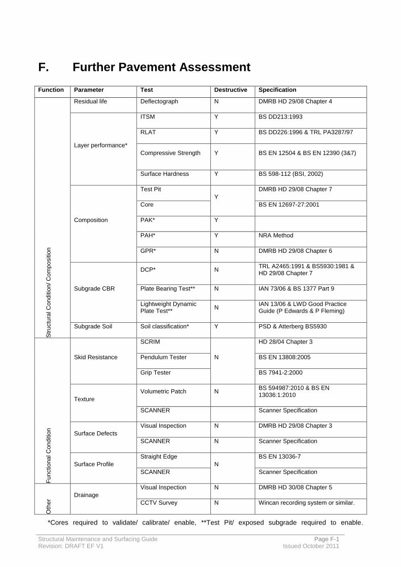
Structural Maintenance and Surfacing Guide Page F-1 Revision: DRAFT EF V1 Issued October 2011
F. Further Pavement Assessment
Function Parameter Test Destructive Specification
Str
uctu
ral C
on
ditio
n/ C
om
po
sitio
n
Residual life Deflectograph N DMRB HD 29/08 Chapter 4
Layer performance*
ITSM Y BS DD213:1993
RLAT Y BS DD226:1996 & TRL PA3287/97
Compressive Strength Y BS EN 12504 & BS EN 12390 (3&7)
Surface Hardness Y BS 598-112 (BSI, 2002)
Composition
Test Pit
Y
DMRB HD 29/08 Chapter 7
Core BS EN 12697-27:2001
PAK* Y
PAH* Y NRA Method
GPR* N DMRB HD 29/08 Chapter 6
Subgrade CBR
DCP* N TRL A2465:1991 & BS5930:1981 & HD 29/08 Chapter 7
Plate Bearing Test** N IAN 73/06 & BS 1377 Part 9
Lightweight Dynamic Plate Test**
N IAN 13/06 & LWD Good Practice Guide (P Edwards & P Fleming)
Subgrade Soil Soil classification* Y PSD & Atterberg BS5930
Fu
nctio
na
l C
on
ditio
n
Skid Resistance
SCRIM
N
HD 28/04 Chapter 3
Pendulum Tester BS EN 13808:2005
Grip Tester BS 7941-2:2000
Texture
Volumetric Patch N BS 594987:2010 & BS EN 13036:1:2010
SCANNER Scanner Specification
Surface Defects
Visual Inspection N DMRB HD 29/08 Chapter 3
SCANNER N Scanner Specification
Surface Profile
Straight Edge
N
BS EN 13036-7
SCANNER Scanner Specification
Oth
er
Drainage
Visual Inspection N DMRB HD 30/08 Chapter 5
CCTV Survey N Wincan recording system or similar.
*Cores required to validate/ calibrate/ enable, **Test Pit/ exposed subgrade required to enable.

Structural Maintenance and Surfacing Guide Page G-1 Revision: DRAFT EF V1 Issued 2011
G. Footways
Footways are situated adjacent to carriageways and carry pedestrians including those with mobility difficulties. The most common causes of failure in footways are vehicle overrun and works by Statutory Undertakers. Structural designs such as those in HD39 allow for varying frequencies of vehicle overrun.
Design guidance for footways (design and maintenance) is given in the following documents;
Gloucestershire Highways Enhanced Materials Policy, Revision 1c, July 2010;
HA design standards for footways;
o HD39/01: Footway Design;
o HD40/01: Footway Maintenance;
TRL Application Guide AG26 (Version 2), Footway and cycle route design, construction and maintenance guide, TRL, 2003;
Design guidance for modular footways;
o BS7533 Pavements constructed with clay, natural stone or concrete pavers.
The surface materials proposed for footways are summarised in Table G1, based on the Gloucestershire Highways Enhanced Materials Policy. The table also indicates the source of each footway design. Cycleway's will generally not require thicker construction than footways; however the surface course should have a low texture as used for footways. Designs for each surface type are given below, with options for ‘light’ and ‘heavy’ vehicle overrun.
Table G1
Surface Type Tables
Surface Material Design
Standard Light Heavy
Light Heavy
Bound surface
G2a G2b Dense asphalt concrete
HD39/01 Table 3.3 2-3 cv/year
Table 3.4 1 cv/day
G3a G3b Concrete pavers BS7533-2: 2001 Table 4
Category IIIa <1 cv/day
Category II <5 cv/day
G4a G4b
Precast concrete flags BS7533-8:2003 1 cv/day 5 cv/day
Natural stone slabs BS7533-8:2003 1 cv/day 5 cv/day
G5a G5b Natural stone setts BS7533-10: 2010
Category III ≤5 sa/day
Category II ≤60 sa/day
Bound & Coloured surface
G6a G6b SMA with exposed aggregate
HD39/01 Table 3.3 2-3 cv/year
Table 3.4 1 cv/day
Unbound G7a G7b Gravel HD25/94 Pedestrian Light vehicle

Structural Maintenance and Surfacing Guide Page G-2 Revision: DRAFT EF V1 Issued 2011
G.1. Maintenance of footways
A footway should provide an even and comfortable surface, free from defects and with few visible signs of surface deterioration. The maintenance objectives are (from AG26):
Ensuring the safety of pedestrians and cyclists;
Maintaining the asset value; and
Maintaining the serviceability.
Highway authorities operate a systematic approach to footway inspections and maintenance
The main structural risk is excessive traffic overrun which will cause deformation (giving an uneven surface) and cracking of the surface which will allow water ingress to the footway foundation layers. Defects in modular footways (pavers, flags etc) include broken, missing or rocking modules.
If defects represent a safety hazard, urgent repair will be needed. Treatment selection flowcharts for asphalt and modular pavements are given in AG26 and HD40.
The principal maintenance treatments needed for various defects are reviewed below. These need to be considered when selecting the surface type. With modular surfacing, it is preferable to match the type/colour of any new pavers or flags with existing.
Surface Material Defect Treatment
Dense asphalt surface
Local cracking or
deformation Structural patch
Extensive cracking or
deformation
Replace surface course or overlay (dense
asphalt)
Fine Cracking Slurry sealing
Defects due to weak
foundation Local reconstruction
Modular surfacing
(Pavers, flags, etc)
Uneven surface due to loss
of jointing sand/bedding
Re-lay on a sand bedding, replacing jointing
sand and sealing joints if necessary
Cracking, excessive
overrun
Re-lay on sand bedding, replacing
damaged modules
Local reconstruction

Structural Maintenance and Surfacing Guide Page G-3 Revision: DRAFT EF V1 Issued 2011
Table G2a: Dense AC – Light vehicle overrun
Pavement Layer
SHW Clause
Materials Grade of Binder
Thickness (mm)
Requirement
Surface Course
909
0/6mm size Dense Asphalt
Concrete
(AC 6 dense surf
100/150)
100/150 20
Surface Appearance: Dark grey/Black
Aggregate: crushed rock or slag
Limestone aggregate not permitted In accord with: BS EN 13108-1: 2006
and PD6691: 2010 Minimum PSV: 55 Maximum AAV: 12
Binder Course
906
0/20mm size Dense Asphalt
Concrete
(AC 20 dense bin
100/150 rec)
100/150 50
Aggregate: crushed rock or slag
Gravel aggregate not permitted In accord with: BS EN 13108-1: 2006
and PD6691: 2010
Sub-base 803 Type 1
Unbound Mixtures
--
CBR mm Aggregate: crushed rock or crushed
concrete An approved proprietary weed killer shall be applied to the surface of the sub-base in accord with the manufacturer’s instructions.
2% 225
3% 200
4% 175
5% 150
Notes: 1. All material within 450mm of the road surface shall be non frost-susceptible as required by the HA SHW
Clause 801.7. This may be reduced to 350mm if the mean annual frost index of the site is proven to be less than 50.
2. Sub-base thickness varies according to the design subgrade CBR. 3. Design based on Table 3.3 of HD39/01.
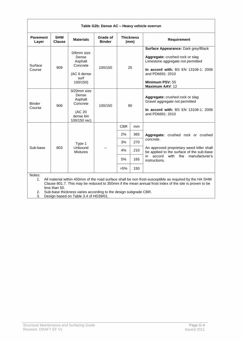
Structural Maintenance and Surfacing Guide Page G-4 Revision: DRAFT EF V1 Issued 2011
Table G2b: Dense AC – Heavy vehicle overrun
Pavement Layer
SHW Clause
Materials Grade of Binder
Thickness (mm)
Requirement
Surface Course
909
0/6mm size Dense Asphalt
Concrete
(AC 6 dense surf
100/150)
100/150 25
Surface Appearance: Dark grey/Black
Aggregate: crushed rock or slag
Limestone aggregate not permitted In accord with: BS EN 13108-1: 2006
and PD6691: 2010 Minimum PSV: 55 Maximum AAV: 12
Binder Course
906
0/20mm size Dense Asphalt
Concrete
(AC 20 dense bin
100/150 rec)
100/150 90
Aggregate: crushed rock or slag
Gravel aggregate not permitted In accord with: BS EN 13108-1: 2006
and PD6691: 2010
Sub-base 803 Type 1
Unbound Mixtures
--
CBR mm
Aggregate: crushed rock or crushed
concrete. An approved proprietary weed killer shall be applied to the surface of the sub-base in accord with the manufacturer’s instructions.
2% 365
3% 270
4% 210
5% 165
>5% 150
Notes: 1. All material within 450mm of the road surface shall be non frost-susceptible as required by the HA SHW
Clause 801.7. This may be reduced to 350mm if the mean annual frost index of the site is proven to be less than 50.
2. Sub-base thickness varies according to the design subgrade CBR. 3. Design based on Table 3.4 of HD39/01.
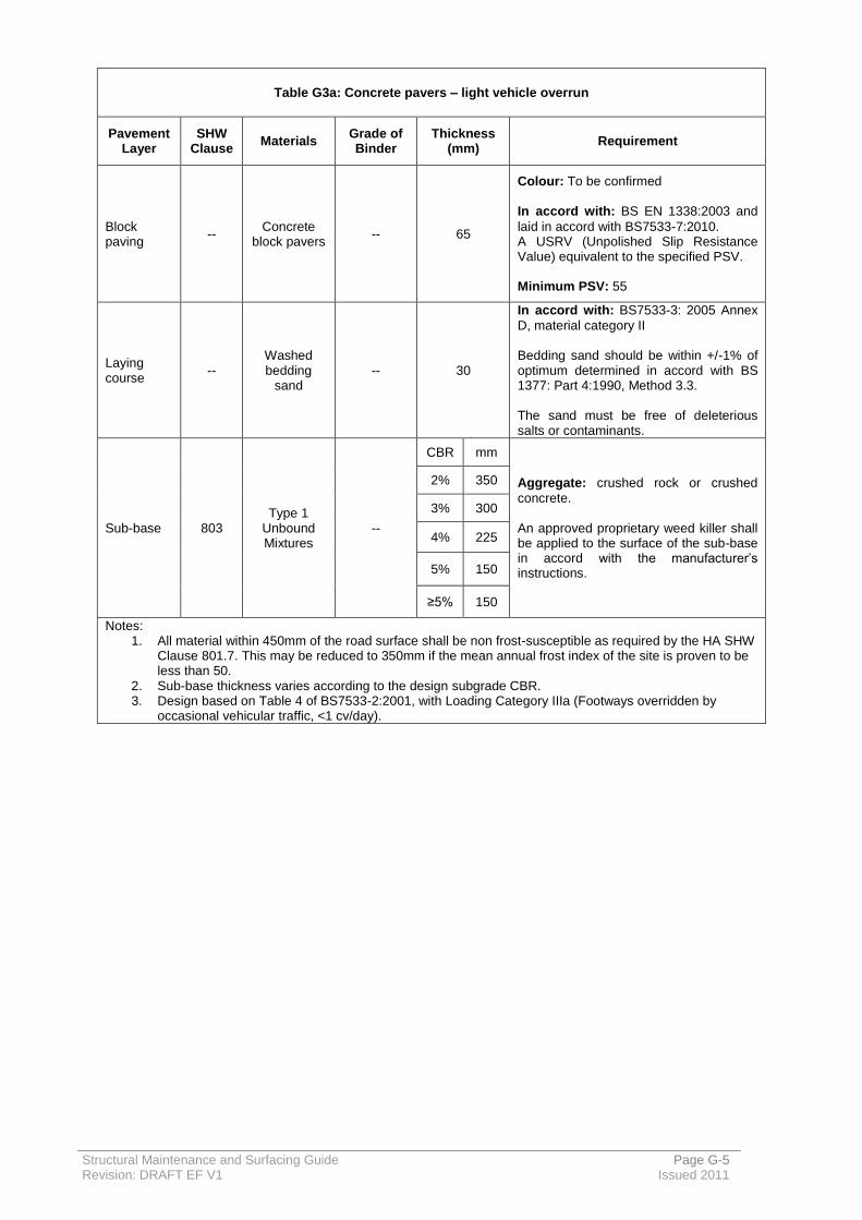
Structural Maintenance and Surfacing Guide Page G-5 Revision: DRAFT EF V1 Issued 2011
Table G3a: Concrete pavers – light vehicle overrun
Pavement Layer
SHW Clause
Materials Grade of Binder
Thickness (mm)
Requirement
Block paving
-- Concrete
block pavers -- 65
Colour: To be confirmed
In accord with: BS EN 1338:2003 and
laid in accord with BS7533-7:2010. A USRV (Unpolished Slip Resistance Value) equivalent to the specified PSV. Minimum PSV: 55
Laying course
-- Washed bedding
sand -- 30
In accord with: BS7533-3: 2005 Annex
D, material category II Bedding sand should be within +/-1% of optimum determined in accord with BS 1377: Part 4:1990, Method 3.3. The sand must be free of deleterious salts or contaminants.
Sub-base 803 Type 1
Unbound Mixtures
--
CBR mm
Aggregate: crushed rock or crushed
concrete. An approved proprietary weed killer shall be applied to the surface of the sub-base in accord with the manufacturer’s instructions.
2% 350
3% 300
4% 225
5% 150
≥5% 150
Notes: 1. All material within 450mm of the road surface shall be non frost-susceptible as required by the HA SHW
Clause 801.7. This may be reduced to 350mm if the mean annual frost index of the site is proven to be less than 50.
2. Sub-base thickness varies according to the design subgrade CBR. 3. Design based on Table 4 of BS7533-2:2001, with Loading Category IIIa (Footways overridden by
occasional vehicular traffic, <1 cv/day).

Structural Maintenance and Surfacing Guide Page G-6 Revision: DRAFT EF V1 Issued 2011
Table G3b: Concrete pavers – heavy vehicle overrun
Pavement Layer
SHW Clause
Materials Grade of Binder
Thickness (mm)
Requirement
Block paving
- Concrete
block pavers -- 65
Colour: To be confirmed
Conforming to BS EN 1338:2003 and laid in accord with BS7533-7:2010. A USRV (Unpolished Slip Resistance Value) equivalent to the specified PSV. Minimum PSV: 55
Laying course
- Washed bedding
sand -- 30
BS7533-3: 2005 Annex D, material category II Bedding sand should be within +/-1% of optimum determined in accord with BS 1377: Part 4:1990, Method 3.3. The sand must be free of deleterious salts or contaminants.
Asphalt Concrete Base
912
Close graded
macadam surface
course used as base
(AC 14 close
surf 100/150)
100/150 125
In accord with: BS EN13108-1:2006
and PD6691: 2010 Clauses 945.1 and 945.2 apply
Sub-base 803 Type 1
Unbound Mixtures
--
CBR mm
Aggregate: crushed rock or crushed
concrete. An approved proprietary weed killer shall be applied to the surface of the sub-base in accord with the manufacturer’s instructions.
2% 400
3% 350
4% 250
5% 150
>5% 150
Notes: 1. All material within 450mm of the road surface shall be non frost-susceptible as required by the HA SHW
Clause 801.7. This may be reduced to 350mm if the mean annual frost index of the site is proven to be less than 50.
2. Sub-base thickness varies according to the design subgrade CBR. 3. Design based on Table 4 of BS7533-2:2001, with Loading Category II (Footways regularly overridden
by vehicular traffic, less than 5cv/day).

Structural Maintenance and Surfacing Guide Page G-7 Revision: DRAFT EF V1 Issued 2011
Table G4a: Concrete flags or Stone slabs – light vehicle overrun
Pavement Layer
SHW Clause
Materials Thickness
(mm) Requirement
Precast Concrete Flags OR Natural Stone Slabs
--
Concrete flags 300x300mm
OR
Stone slabs 300x300mm
60
60
Colour: To be confirmed
Precast Concrete Flags: Conforming to BS EN
1339:2003 and laid in accord with BS7533-4. OR Natural Stone Slabs: Conforming to BS EN
1341:2003 and laid in accord with BS7533-4. Joint filler material to BS7533-3:2005 Annex D, section D.1.2. Joint filler material shall be stabilized with a surface applied elastomeric sealant. A USRV (Unpolished Slip Resistance Value) equivalent to the specified PSV. Minimum PSV: 45
Laying course
-- Washed bedding
sand 30
BS7533-3: 2005 Annex D, material category II Bedding sand should be within +/-1% of optimum determined in accord with BS 1377: Part 4:1990, Method 3.3. The sand must be free of deleterious salts or contaminants.
Sub-base 803 Type 1 Unbound
Mixture
CBR mm
Aggregate: crushed rock or crushed concrete.
An approved proprietary weed killer shall be applied to the surface of the sub-base in accord with the manufacturer’s instructions.
2% 375
3% 275
5% 200
≥7% 125
Notes: 1. All material within 450mm of the road surface shall be non frost-susceptible as required by the HA SHW
Clause 801.7. This may be reduced to 350mm if the mean annual frost index of the site is proven to be less than 50.
2. Sub-base thickness varies according to the design subgrade CBR. 3. Design based on BS7533-8:2003, for design loading 1cv/day over 40 years.
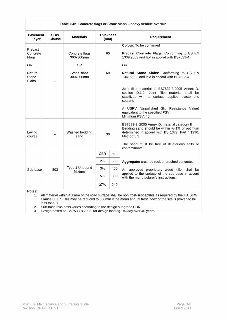
Structural Maintenance and Surfacing Guide Page G-8 Revision: DRAFT EF V1 Issued 2011
Table G4b: Concrete flags or Stone slabs – heavy vehicle overrun
Pavement Layer
SHW Clause
Materials Thickness
(mm) Requirement
Precast Concrete Flags OR Natural Stone Slabs
--
Concrete flags 300x300mm
OR
Stone slabs 300x300mm
60
60
Colour: To be confirmed
Precast Concrete Flags: Conforming to BS EN
1339:2003 and laid in accord with BS7533-4. OR Natural Stone Slabs: Conforming to BS EN
1341:2003 and laid in accord with BS7533-4. Joint filler material to BS7533-3:2005 Annex D, section D.1.2. Joint filler material shall be stabilized with a surface applied elastomeric sealant. A USRV (Unpolished Slip Resistance Value) equivalent to the specified PSV. Minimum PSV: 45
Laying course
-- Washed bedding
sand 30
BS7533-3: 2005 Annex D, material category II Bedding sand should be within +/-1% of optimum determined in accord with BS 1377: Part 4:1990, Method 3.3. The sand must be free of deleterious salts or contaminants.
Sub-base 803 Type 1 Unbound
Mixture
CBR mm
Aggregate: crushed rock or crushed concrete.
An approved proprietary weed killer shall be applied to the surface of the sub-base in accord with the manufacturer’s instructions.
2% 500
3% 400
5% 300
≥7% 240
Notes: 1. All material within 450mm of the road surface shall be non frost-susceptible as required by the HA SHW
Clause 801.7. This may be reduced to 350mm if the mean annual frost index of the site is proven to be less than 50.
2. Sub-base thickness varies according to the design subgrade CBR. 3. Design based on BS7533-8:2003, for design loading 1cv/day over 40 years.

Structural Maintenance and Surfacing Guide Page G-9 Revision: DRAFT EF V1 Issued 2011
Table G5a: Stone Setts – light vehicle overrun
Pavement Layer
SHW Clause
Materials Thickness
(mm) Requirement
Natural Stone Setts
-- Size 1 Full Sett
50x100mm 50
Colour: To be confirmed
Conforming to: BS EN 1342:2001 and laid in
accord with BS7533-7. Design joint width: 6-10mm Jointing mortar compressive strength:
40N/mm2, (BS7533-7 Table C.5).
A USRV (Unpolished Slip Resistance Value) equivalent to the specified PSV. Minimum PSV: 45
Laying course
-- Type B Mortar 40mm (moist)
OR 30mm (plastic)
Laid in accord with: BS7533-7, clause 8.5.1.
Bedding Mortar Type B (BS7533-7, Table C.4)
Sub-base 803 Type 1 Unbound
Mixture
CBR mm
Aggregate: crushed rock or crushed concrete.
An approved proprietary weed killer shall be applied to the surface of the sub-base in accord with the manufacturer’s instructions.
2% 300
3% 275
4% 250
≥5% 150
Notes: 1. All material within 450mm of the road surface shall be non frost-susceptible as required by the HA SHW
Clause 801.7. This may be reduced to 350mm if the mean annual frost index of the site is proven to be less than 50.
2. Sub-base thickness varies according to the design subgrade CBR. 3. Design based on BS7533-10:2003, for design loading Category III.
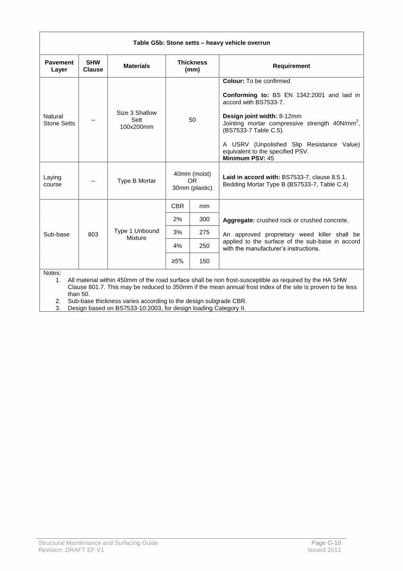
Structural Maintenance and Surfacing Guide Page G-10 Revision: DRAFT EF V1 Issued 2011
Table G5b: Stone setts – heavy vehicle overrun
Pavement Layer
SHW Clause
Materials Thickness
(mm) Requirement
Natural Stone Setts
-- Size 3 Shallow
Sett 100x200mm
50
Colour: To be confirmed
Conforming to: BS EN 1342:2001 and laid in
accord with BS7533-7. Design joint width: 8-12mm
Jointing mortar compressive strength 40N/mm2,
(BS7533-7 Table C.5). A USRV (Unpolished Slip Resistance Value) equivalent to the specified PSV. Minimum PSV: 45
Laying course
-- Type B Mortar 40mm (moist)
OR 30mm (plastic)
Laid in accord with: BS7533-7, clause 8.5.1.
Bedding Mortar Type B (BS7533-7, Table C.4)
Sub-base 803 Type 1 Unbound
Mixture
CBR mm
Aggregate: crushed rock or crushed concrete.
An approved proprietary weed killer shall be applied to the surface of the sub-base in accord with the manufacturer’s instructions.
2% 300
3% 275
4% 250
≥5% 150
Notes: 1. All material within 450mm of the road surface shall be non frost-susceptible as required by the HA SHW
Clause 801.7. This may be reduced to 350mm if the mean annual frost index of the site is proven to be less than 50.
2. Sub-base thickness varies according to the design subgrade CBR. 3. Design based on BS7533-10:2003, for design loading Category II.
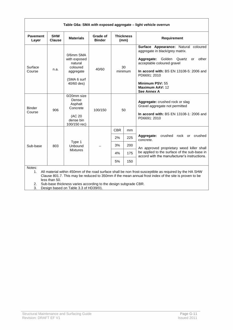
Structural Maintenance and Surfacing Guide Page G-11 Revision: DRAFT EF V1 Issued 2011
Table G6a: SMA with exposed aggregate – light vehicle overrun
Pavement Layer
SHW Clause
Materials Grade of Binder
Thickness (mm)
Requirement
Surface Course
n.a.
0/6mm SMA with exposed
natural coloured
aggregate
(SMA 6 surf 40/60 des)
40/60 30
minimum
Surface Appearance: Natural coloured
aggregate in black/grey matrix. Aggregate: Golden Quartz or other
acceptable coloured gravel In accord with: BS EN 13108-5: 2006 and
PD6691: 2010 Minimum PSV: 55 Maximum AAV: 12 See Annex A
Binder Course
906
0/20mm size Dense Asphalt
Concrete
(AC 20 dense bin
100/150 rec)
100/150 50
Aggregate: crushed rock or slag
Gravel aggregate not permitted In accord with: BS EN 13108-1: 2006 and
PD6691: 2010
Sub-base 803 Type 1
Unbound Mixtures
--
CBR mm
Aggregate: crushed rock or crushed
concrete. An approved proprietary weed killer shall be applied to the surface of the sub-base in accord with the manufacturer’s instructions.
2% 225
3% 200
4% 175
5% 150
Notes: 1. All material within 450mm of the road surface shall be non frost-susceptible as required by the HA SHW
Clause 801.7. This may be reduced to 350mm if the mean annual frost index of the site is proven to be less than 50.
2. Sub-base thickness varies according to the design subgrade CBR. 3. Design based on Table 3.3 of HD39/01.

Structural Maintenance and Surfacing Guide Page G-12 Revision: DRAFT EF V1 Issued 2011
Table G6b: SMA with exposed aggregate – heavy vehicle overrun
Pavement Layer
SHW Clause
Materials Grade of Binder
Thickness (mm)
Requirement
Surface Course
n.a.
0/6mm SMA with exposed
natural coloured
aggregate
(SMA 6 surf 40/60 des)
40/60 30
minimum
Surface Appearance: Natural coloured
aggregate in black/grey matrix. Aggregate: Golden Quartz or other
acceptable coloured gravel In accord with: BS EN 13108-5: 2006 and
PD6691: 2010 Minimum PSV: 55 Maximum AAV: 12 See Annex A
Binder Course
906
0/20mm size Dense Asphalt
Concrete
(AC 20 dense bin
100/150 rec)
100/150 90
Aggregate: crushed rock or slag
Gravel aggregate not permitted In accord with: BS EN 13108-1: 2006 and
PD6691: 2010
Sub-base 803 Type 1
Unbound Mixtures
--
CBR mm
Aggregate: crushed rock or crushed
concrete. An approved proprietary weed killer shall be applied to the surface of the sub-base in accord with the manufacturer’s instructions.
2% 365
3% 270
4% 210
5% 165
>5% 150
Notes: 1. All material within 450mm of the road surface shall be non frost-susceptible as required by the HA SHW
Clause 801.7. This may be reduced to 350mm if the mean annual frost index of the site is proven to be less than 50.
2. Sub-base thickness varies according to the design subgrade CBR. 3. Design based on Table 3.4 of HD39/01.
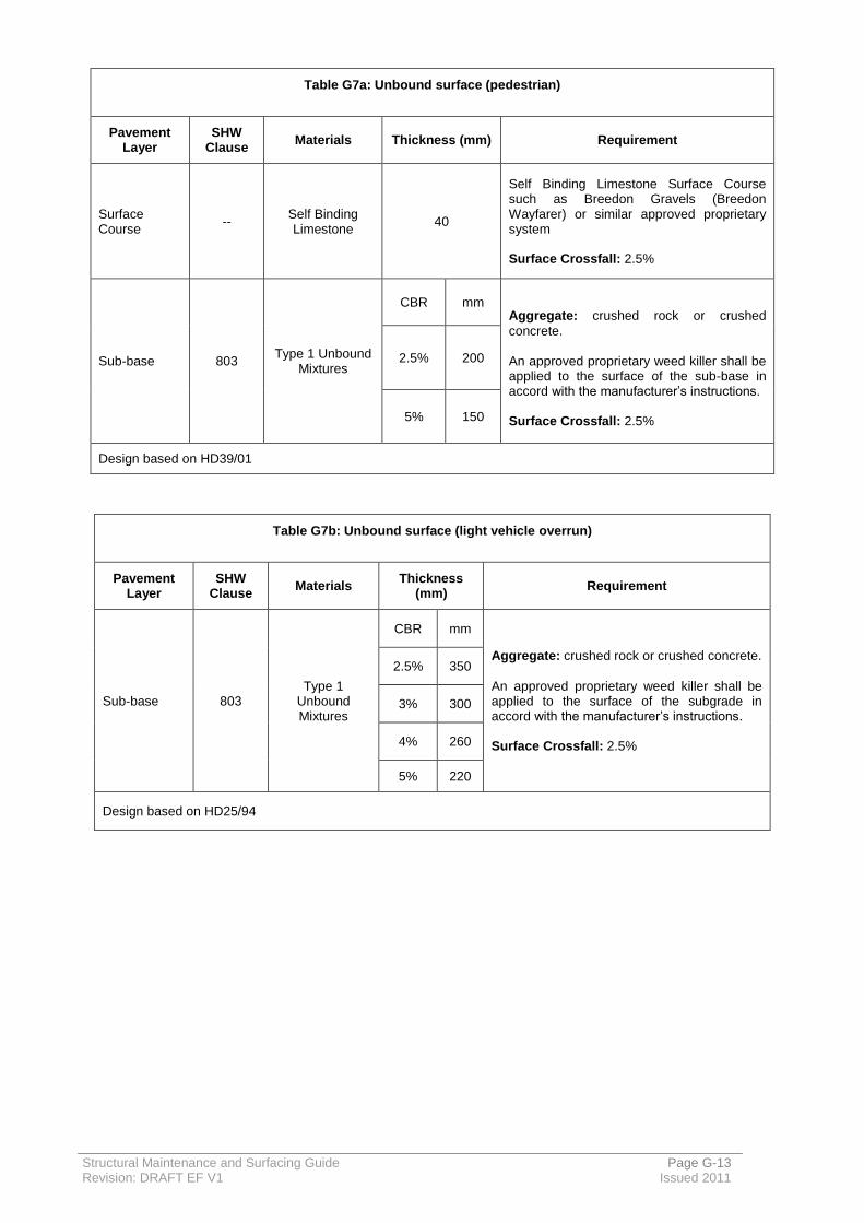
Structural Maintenance and Surfacing Guide Page G-13 Revision: DRAFT EF V1 Issued 2011
Table G7a: Unbound surface (pedestrian)
Pavement Layer
SHW Clause
Materials Thickness (mm) Requirement
Surface Course
-- Self Binding Limestone
40
Self Binding Limestone Surface Course such as Breedon Gravels (Breedon Wayfarer) or similar approved proprietary system Surface Crossfall: 2.5%
Sub-base 803 Type 1 Unbound
Mixtures
CBR mm Aggregate: crushed rock or crushed
concrete. An approved proprietary weed killer shall be applied to the surface of the sub-base in accord with the manufacturer’s instructions. Surface Crossfall: 2.5%
2.5% 200
5% 150
Design based on HD39/01
Table G7b: Unbound surface (light vehicle overrun)
Pavement Layer
SHW Clause
Materials Thickness
(mm) Requirement
Sub-base 803 Type 1
Unbound Mixtures
CBR mm
Aggregate: crushed rock or crushed concrete.
An approved proprietary weed killer shall be applied to the surface of the subgrade in accord with the manufacturer’s instructions. Surface Crossfall: 2.5%
2.5% 350
3% 300
4% 260
5% 220
Design based on HD25/94

Structural Maintenance and Surfacing Guide Page G-14 Revision: DRAFT EF V1 Issued 2011
G.2. Annex A – Proprietary stone mastic asphalt surface course with exposed aggregate finish
Information to be provided by the Contractor
1. The Contractor shall provide a full installation method for the proprietary system.
2. The Contractor shall allow for undertaking up to 4 trial panels of at least 1 tonne each or a minimum of 4m2 in order to demonstrate both the process and finish. This shall be undertaken on site within 2 weeks of being appointed. The trial panels will include gravel aggregate combinations to be agreed at the time of appointment and will represent the surface finish to be achieved throughout subsequent works.
3. Samples of the Aggregates to be used within the SMA surface course shall be supplied to The Engineer for inspection and approval.
4. The Proprietary surface course system will be a proven system with contractors being able to demonstrate not only successfully laying the material but also successful removal of the bitumen film from the surface in order to expose the coloured aggregate.
5. The Contractor shall demonstrate that the process of removing the bitumen to expose the aggregate surface does not damage the integrity of the Stone Mastic Asphalt in any way – any damage caused shall result in the whole surfacing length being removed.
6. The Contactor shall demonstrate that the bitumen removal process is friendly to the environment with any excess residue caused by the process being immediately removed by a suction process without any deleterious effect on the adjacent soft landscaping and local wildlife.
7. The Contractor shall provide information on the Bond Coat to be used at the interface with the underlying asphalt layer to demonstrate it provides a durable and effective bond. In order to achieve this, a polymer modified bond coat such as Colbond 50 or equivalent is required between the SMA surface course and the underlying bituminous substrate.
8. It is likely that the aggregate within the SMA surface course will include natural gravel – information is required to confirm that appropriate adhesion agents are to be added to ensure good adhesion takes place between the aggregate and the bitumen.

Structural Maintenance and Surfacing Guide Page G-15 Revision: DRAFT EF V1 Issued 2011
Additional Key Information for the Surfacing Operation.
1. All materials must be transported, laid and compacted fully in accord with the requirements of BS 594987:2010.
2. All joints within all layers should be cut back to a sound, vertical face and painted in accord with BS 594987: 2010.
3. All surfaces (whether new or existing) shall be Bond coated in accord with the requirements of Clause 5.5, within BS 594987: 2010. The underlying surface must be clean and not contaminated prior to the installation of any Bond Coat. The Bond Coat shall be tanker applied in accord with SHW Clause 920 – localised small areas may be hand sprayed.
4. All Transverse Joints or Longitudinal Joints not tightly finished shall be overbanded with 40/60 or 70/100 pen hot applied bitumen at a width less than 40mm or as agreed with The Engineer.
5. All areas must be tested to ensure regularity compliance in accord with Schedule 2 – testing to be undertaken by the Contractor using a UKAS accredited test house.
6. All areas must be tested to ensure surface texture compliance in accord with Schedule 2 – testing to be undertaken by the contractor UKAS accredited test house

Structural Maintenance and Surfacing Guide Page H-1 Revision: DRAFT EF V1 Issued 2011
H. Surfacing over Bridge Decks
H.1. Background to surfacing over bridges
Care should be taken when undertaking any surfacing scheme which crosses over a bridge deck, particularly where the deck is at a shallow depth to the road surface, or alongside a highway retaining wall. As a minimum, brief consultation with the GH Bridges team is recommended to establish what records exist for the structure which may impact on the material specification or method of laying.
Some issues to take account of are:
Bridge deck type – Bridges with concrete slabs need effective waterproofing and surfacing to avoid long term damage from chloride ingress as a result of de-icing salts. Although many GCC bridges are arches, these have frequently been strengthened, and so a concrete overslab or other types of strengthening (e.g. retro reinforcement) may be present at a shallow depth. Some may have weak cantilevers or other details which must not be overloaded;
Surfacing depth – a key criteria in determining the surfacing specification. Often the presence of kerbs/parapet edge beams make overlay impracticable. Where overlay is considered this must be accepted by the Bridges Team as an acceptable additional loading.
Presence of waterproofing to concrete or steel surface;
Statutory undertakers apparatus is also frequently at very shallow depth over bridge decks;
Presence of bridge deck movement joints;
Condition of structure – masonry structures in poor condition can be easily damaged through vibrating rollers or other surfacing plant.
The waterproofing and surfacing replacement on bridge decks needs special care and attention to ensure that the work carried out is specified in accord with best design practice procedures and that the subsequent work carried out provides a durable and maintenance free pavement and minimises future whole life costs.

Structural Maintenance and Surfacing Guide Page H-2 Revision: DRAFT EF V1 Issued 2011
H.2. Standards relating to surfacing/ waterproofing
Guidance on surfacing to bridge decks is given in the following documents:
BD47/99 & BA47/99: Waterproofing and surfacing of bridge decks
IAN96/07 Rev1 ‘Guidance on implementing results of research on bridge deck waterproofing’
TRL report TRL655: Asphalt surfacing to bridge decks (Nicholls, Jordan and Hassan).
For new works, BD47 requires a minimum 100mm of surfacing material excluding the waterproofing system and the Additional Protective layer (APL). The APL has a nominal thickness 20mm.
IAN96/07 advises that the APL should only be used when required by the waterproofing system. Modern spray applied acrylic/plastic membranes which have BBA/HAPAS accreditation generally do not require the protection of an APL (see section H3 for further detail on APL). The BBA assessment checks the resistance to aggregate indentation at 125⁰C for the waterproofing system and specific asphalt overlay. In
addition, the use of a Clause 943 HRA binder course (minimum thickness 45mm) is recommended.
For existing structures, the minimum thickness will be generally dictated by existing circumstances. However generally a minimum of 60mm should be achieved. It should be noted that higher bond and adhesion strengths are required where surfacing thicknesses are reduced (reference IAN96/07 Rev 1).
For steel decks, a combined waterproofing and surfacing system can be specified – however this is outside of the scope of this guidance, and the bridges team should be consulted.
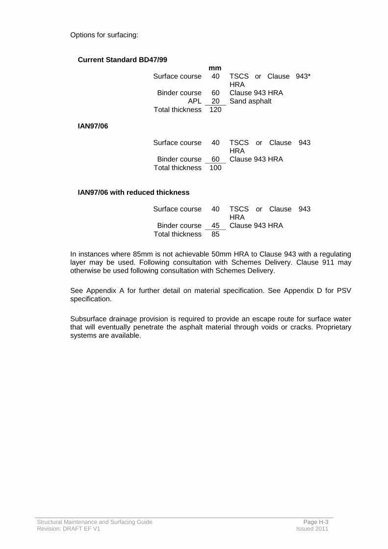
Structural Maintenance and Surfacing Guide Page H-3 Revision: DRAFT EF V1 Issued 2011
Options for surfacing:
Current Standard BD47/99 mm
Surface course 40 TSCS or Clause 943* HRA
Binder course 60 Clause 943 HRA APL 20 Sand asphalt
Total thickness 120
IAN97/06
Surface course 40 TSCS or Clause 943 HRA
Binder course 60 Clause 943 HRA
Total thickness 100
IAN97/06 with reduced thickness
Surface course 40 TSCS or Clause 943 HRA
Binder course 45 Clause 943 HRA
Total thickness 85
In instances where 85mm is not achievable 50mm HRA to Clause 943 with a regulating layer may be used. Following consultation with Schemes Delivery. Clause 911 may otherwise be used following consultation with Schemes Delivery.
See Appendix A for further detail on material specification. See Appendix D for PSV specification.
Subsurface drainage provision is required to provide an escape route for surface water that will eventually penetrate the asphalt material through voids or cracks. Proprietary systems are available.

Structural Maintenance and Surfacing Guide Page H-4 Revision: DRAFT EF V1 Issued 2011
Verge/footway treatment
On most bridge decks, there is a verge or footway present between the edge of carriageway and the parapet. Where the verge is not surfaced, normally the opportunity should be taken to surface this to help prevent water ingress. A kerb upstand should normally be provided, but this will depend on various factors that are outside the scope of this guidance note.
For surfacing of the verges the following options are normally undertaken over the waterproofing layer:
Option 1 (preferred)
ST2* concrete + 25mm surface course
Option 2
Protection to waterproofing layer (dependant on system) – sand blinding/membrane
Type 1 subbase + 50mm Binder course + 25mm Surface course
*Use of ST2 concrete at the ends of the deck may be advisable to help prevent damage to the bridge deck by utility companies.
Guidance on subsurface drainage (H5) should be referred to. Care must be taken when detailing of surfacing/waterproofing around utilities in verges as these often provide an easy route for surface water to seep through to the bridge deck.

Structural Maintenance and Surfacing Guide Page H-5 Revision: DRAFT EF V1 Issued 2011
H.3. Asphalt Protective Layer (APL) or other indicator layers/protection
Traditional materials such as Mastic Asphalt, which for many years has been used as a combined waterproofing and surfacing layer and Hot Rolled Asphalt (HRA) surfacing course and Asphalt Protection Layer (APL) (sometimes tinted red) are now being replaced by modern materials due to recent developments in waterproofing materials and changes in working practices.
Spray applied acrylic/ plastic membranes complying with BBA/HA approvals have now largely replaced bitumen impregnated sheeting. These materials have been proven to be very tough compared to traditional waterproofing materials and hence do not require the traditional 20mm of Sand Asphalt APL.
Many projects have now taken place where the APL has been excluded in conjunction with acrylic spray applied waterproofing on structures where limitations on kerb height and weight restrictions have applied and modern 942 thin surfacing has been used successfully. Omitting the APL is beneficial as it reduces the thickness of the surfacing and has been difficult to lay. However these new materials are more permeable than the traditional HRA and they need special care when being used in the surfacing course of bridges and other structures.
Indicator meshes have also been used on some previous schemes to help highlight the presence of the bridge deck to utility companies or surfacing contractors, to prevent damage to the bridge deck. However there is little evidence to suggest that these are working in practise, and are not typically used on GH projects.
Where granular material is to be used directly on top of waterproofing layers, or the waterproofing layer is to be trafficked during construction, particular caution needs to be taken to avoid damage to the new waterproofing layer. Certain approved waterproofing systems are designed to be more resistant to aggregate damage which may be more suitable for this purpose. Alternatively a temporary or permanent protection board may be used to prevent damage; however the waterproofing manufacturer should be consulted if failure of the bond between waterproofing and surfacing would cause issues.
H.4. Waterproofing / surfacing interface bond / compaction
The bond between the waterproofing and the asphalt surfacing is achieved when the heat from the asphalt binder / shaping course activates the SA 1030 tack coat and this then fuses with the acrylic waterproofing to form a strong mechanical bond with the asphalt.
It is therefore essential that the manufacture of the asphalt is carried out in accord with Table 7 of BS 594-1: 2003 and that the delivery temperature is maintained at the highest temperature possible.
In laying the asphalt this should be done with the minimum of delay to ensure that bond with the waterproofing is activated, that the voids in the mixture minimised and compaction achieved without causing undue displacement (pushing / micro-cracking) of the asphalt.
Compaction shall be completed in accord with Table 6 of BS 594- 2:2003.
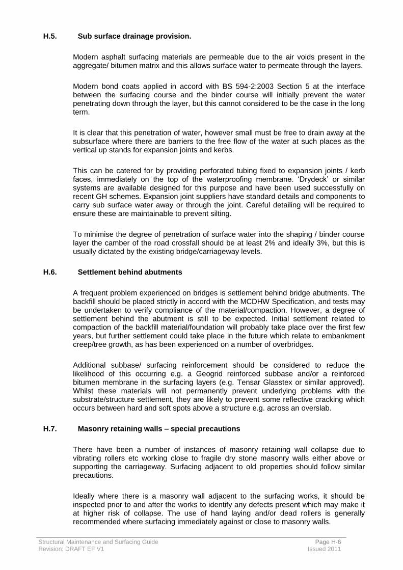
Structural Maintenance and Surfacing Guide Page H-6 Revision: DRAFT EF V1 Issued 2011
H.5. Sub surface drainage provision.
Modern asphalt surfacing materials are permeable due to the air voids present in the aggregate/ bitumen matrix and this allows surface water to permeate through the layers.
Modern bond coats applied in accord with BS 594-2:2003 Section 5 at the interface between the surfacing course and the binder course will initially prevent the water penetrating down through the layer, but this cannot considered to be the case in the long term.
It is clear that this penetration of water, however small must be free to drain away at the subsurface where there are barriers to the free flow of the water at such places as the vertical up stands for expansion joints and kerbs.
This can be catered for by providing perforated tubing fixed to expansion joints / kerb faces, immediately on the top of the waterproofing membrane. ‘Drydeck’ or similar systems are available designed for this purpose and have been used successfully on recent GH schemes. Expansion joint suppliers have standard details and components to carry sub surface water away or through the joint. Careful detailing will be required to ensure these are maintainable to prevent silting.
To minimise the degree of penetration of surface water into the shaping / binder course layer the camber of the road crossfall should be at least 2% and ideally 3%, but this is usually dictated by the existing bridge/carriageway levels.
H.6. Settlement behind abutments
A frequent problem experienced on bridges is settlement behind bridge abutments. The backfill should be placed strictly in accord with the MCDHW Specification, and tests may be undertaken to verify compliance of the material/compaction. However, a degree of settlement behind the abutment is still to be expected. Initial settlement related to compaction of the backfill material/foundation will probably take place over the first few years, but further settlement could take place in the future which relate to embankment creep/tree growth, as has been experienced on a number of overbridges.
Additional subbase/ surfacing reinforcement should be considered to reduce the likelihood of this occurring e.g. a Geogrid reinforced subbase and/or a reinforced bitumen membrane in the surfacing layers (e.g. Tensar Glasstex or similar approved). Whilst these materials will not permanently prevent underlying problems with the substrate/structure settlement, they are likely to prevent some reflective cracking which occurs between hard and soft spots above a structure e.g. across an overslab.
H.7. Masonry retaining walls – special precautions
There have been a number of instances of masonry retaining wall collapse due to vibrating rollers etc working close to fragile dry stone masonry walls either above or supporting the carriageway. Surfacing adjacent to old properties should follow similar precautions.
Ideally where there is a masonry wall adjacent to the surfacing works, it should be inspected prior to and after the works to identify any defects present which may make it at higher risk of collapse. The use of hand laying and/or dead rollers is generally recommended where surfacing immediately against or close to masonry walls.
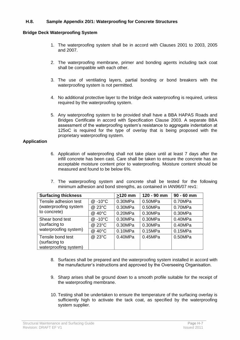
Structural Maintenance and Surfacing Guide Page H-7 Revision: DRAFT EF V1 Issued 2011
H.8. Sample Appendix 20/1: Waterproofing for Concrete Structures
Bridge Deck Waterproofing System
1. The waterproofing system shall be in accord with Clauses 2001 to 2003, 2005 and 2007.
2. The waterproofing membrane, primer and bonding agents including tack coat shall be compatible with each other.
3. The use of ventilating layers, partial bonding or bond breakers with the waterproofing system is not permitted.
4. No additional protective layer to the bridge deck waterproofing is required, unless required by the waterproofing system.
5. Any waterproofing system to be provided shall have a BBA HAPAS Roads and Bridges Certificate in accord with Specification Clause 2003. A separate BBA assessment of the waterproofing system’s resistance to aggregate indentation at 125oC is required for the type of overlay that is being proposed with the proprietary waterproofing system.
Application
6. Application of waterproofing shall not take place until at least 7 days after the infill concrete has been cast. Care shall be taken to ensure the concrete has an acceptable moisture content prior to waterproofing. Moisture content should be measured and found to be below 6%.
7. The waterproofing system and concrete shall be tested for the following minimum adhesion and bond strengths, as contained in IAN96/07 rev1:
8. Surfaces shall be prepared and the waterproofing system installed in accord with the manufacturer’s instructions and approved by the Overseeing Organisation.
9. Sharp arises shall be ground down to a smooth profile suitable for the receipt of the waterproofing membrane.
10. Testing shall be undertaken to ensure the temperature of the surfacing overlay is sufficiently high to activate the tack coat, as specified by the waterproofing system supplier.
Surfacing thickness >120 mm 120 - 90 mm 90 - 60 mm
Tensile adhesion test (waterproofing system to concrete)
@ -10°C 0.30MPa 0.50MPa 0.70MPa
@ 23°C 0.30MPa 0.50MPa 0.70MPa
@ 40°C 0.20MPa 0.30MPa 0.30MPa
Shear bond test (surfacing to waterproofing system)
@ -10°C 0.30MPa 0.30MPa 0.40MPa
@ 23°C 0.30MPa 0.30MPa 0.40MPa
@ 40°C 0.10MPa 0.15MPa 0.15MPa
Tensile bond test (surfacing to waterproofing system)
@ 23°C 0.40MPa 0.45MPa 0.50MPa
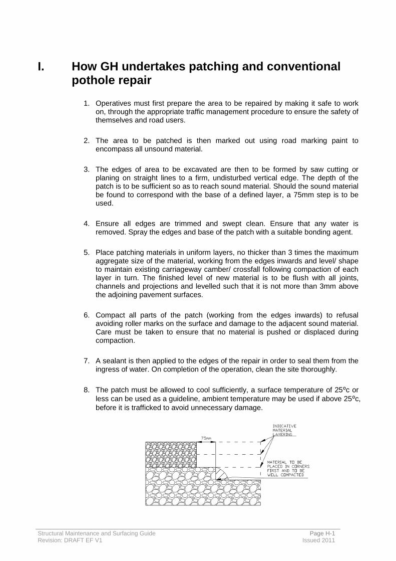
Structural Maintenance and Surfacing Guide Page H-1 Revision: DRAFT EF V1 Issued 2011
I. How GH undertakes patching and conventional pothole repair
1. Operatives must first prepare the area to be repaired by making it safe to work on, through the appropriate traffic management procedure to ensure the safety of themselves and road users.
2. The area to be patched is then marked out using road marking paint to encompass all unsound material.
3. The edges of area to be excavated are then to be formed by saw cutting or planing on straight lines to a firm, undisturbed vertical edge. The depth of the patch is to be sufficient so as to reach sound material. Should the sound material be found to correspond with the base of a defined layer, a 75mm step is to be used.
4. Ensure all edges are trimmed and swept clean. Ensure that any water is removed. Spray the edges and base of the patch with a suitable bonding agent.
5. Place patching materials in uniform layers, no thicker than 3 times the maximum aggregate size of the material, working from the edges inwards and level/ shape to maintain existing carriageway camber/ crossfall following compaction of each layer in turn. The finished level of new material is to be flush with all joints, channels and projections and levelled such that it is not more than 3mm above the adjoining pavement surfaces.
6. Compact all parts of the patch (working from the edges inwards) to refusal avoiding roller marks on the surface and damage to the adjacent sound material. Care must be taken to ensure that no material is pushed or displaced during compaction.
7. A sealant is then applied to the edges of the repair in order to seal them from the ingress of water. On completion of the operation, clean the site thoroughly.
8. The patch must be allowed to cool sufficiently, a surface temperature of 25⁰c or
less can be used as a guideline, ambient temperature may be used if above 25⁰c,
before it is trafficked to avoid unnecessary damage.