Global VSAT Forum
32
Global VSAT Forum Auto-Deploy Terminal Type Approval GVF-104 Rev 6 [25 October 2016] Page 1 Global VSAT Forum PERFORMANCE AND TEST GUIDELINES FOR TYPE APPROVAL OF AUTO-DEPLOY AND VMES SATELLITE COMMUNICATIONS TERMINALS GVF-104 This document defines the applicable performance requirements and test procedures for GVF Type Approval of Auto-Deploy and Vehicle Mounted Earth Station (VMES) VSAT communications antenna systems.
Transcript of Global VSAT Forum
Global VSAT Forum Auto-Deploy Terminal Type Approval
GVF-104 Rev 6 [25 October 2016] Page 1
Global VSAT Forum
PERFORMANCE AND TEST GUIDELINES FOR TYPE APPROVAL OF AUTO-DEPLOY AND VMES SATELLITE COMMUNICATIONS TERMINALS
GVF-104
This document defines the applicable performance requirements and test procedures for GVF Type Approval of Auto-Deploy and Vehicle Mounted Earth Station (VMES) VSAT communications antenna systems.

Global VSAT Forum Auto-Deploy Terminal Type Approval
GVF-104 Rev 6 [25 October 2016] Page 2
Revision History: Revision Date Notes Rev 0 CMR / Draft document Rev 1 25 Feb 2010 Restructured and created Appendix A. Added specification
document reference detail. Incorporated comments for CMR. (RLB)
Rev 2 3 Mar 2010 Edited (DH/RLB) and incorporating assessment of two pointing error tests (FF), as well as further input arising from meeting of drafting group
Rev 3 31 May 2010 Incorporates comments received at the last meeting of the drafting group on the 30 April 2010
Rev 4 10 Jun 2010 Expands definitions and configurations of the terminals Rev 4.1 28 Feb 2011 Amends editorial errors Rev 5 24 Apr 2013 CMR / Amend document to include Eutelsat addendum Rev 6 25 Oct 2016 Added Ka-band and new performance section; referred stabilized
antennas to GVF 105; updated FCC and Eutelsat Ku-band performance requirements / regulations;
Table of Contents 1 Purpose .................................................................................................................................... 32 Terminal Definition ................................................................................................................... 33 Performance Requirements ..................................................................................................... 4
3.1 Co-pol Off-Axis EIRP Spectral Density (EIRPSD) Mask ................................................... 43.2 Cross-pol Off-Axis EIRP Spectral Density (EIRPSD) Mask .............................................. 53.3 Cross-pol Discrimination (XPD) ........................................................................................ 53.4 Antenna Pointing Accuracy ............................................................................................... 6
4 Type Approval Test Requirements ........................................................................................... 94.1 Pre-defined parameters .................................................................................................... 94.2 Required Tests .................................................................................................................. 74.3 Test Methods .................................................................................................................. 10
A. Appendix: Background Notes ................................................................................................... 91. The GVF Auto-Deploy Type Approval Initiative .................................................................... 92. Off-axis EIRP Spectral Density Regulations ....................................................................... 10
B. Appendix: Performance Envelope ......................................................................................... 15 ADDENDUM: Auto-Deploy Approval: Step-by-Step Procedures -- [Prepared by Fulvio Fresia, 02 Feb 2013]
Global VSAT Forum Auto-Deploy Terminal Type Approval
GVF-104 Rev 6 [25 October 2016] Page 3
1 Purpose This document is intended to serve as a best-practices guide for interpreting international regulatory specifications for the purpose of GVF type approval of auto-deploy VSAT terminals. The GVF type approval process is defined in detail in document GVF-101. That document assumes that the satellite operator for whom the type approval is to be issued defines performance specifications. It is the objective of this document to provide best-practices guidance to satellite operators who wish to offer a type approval for auto-deploy terminals, or for use in GVF-issued type approvals. GVF-101 also defines general test procedures for VSAT terminals. This document adds guidance for testing parameters that are unique to auto-deploy terminals.
2 Terminal Definition An auto-deploy terminal is defined for the purposes of this document as follows:
a) C, Ku or Ka-band operation.
b) Intended for operation on geostationary (non-inclined) satellites.
c) Automatically deploys, and accurately points, its antenna towards a designated target satellite.
d) Includes the following types of motorized platforms: (1) fixed (automatically deploys and
points); (2) semi-fixed (automatically deploys and points but can compensate in real time for small movements of its base, like people getting in or out of a stationary vehicle). Stabilized (fully stabilized and suitable for vessels and moving vehicles) platforms are addressed in GVF 105.
e) Either (1) operates as part of a managed network, in which there is a hub or other counterpart earth station that is required for the terminal to operate and which supports terminal operations, or (2) operates as a standalone uplink station and all control functions are self-contained.
f) The type approval is granted to an agreed unique configuration, comprising the antenna (identified by manufacturer, model and diameter), mount, antenna control system, RF chain and modem. The maximum allowed EIRP density will be defined on the basis of the antenna RF performance and the results of the auto-deploy tests. The existing communication between modem and the platform shall be fully explained by the manufacturer e.g. presence of power control in the modem, modem locking signal characteristics etc. In case of a different type of modem replacing the one of the originally type approved configuration, additional test plans will have to be mutually agreed between the applicant and the ATE (Authorized test Entity). If the manufacturer demonstrates that the pointing and RF parameters are not subject to a high level of modem dependency, other types of modems can be validated by analysis only.

Global VSAT Forum Auto-Deploy Terminal Type Approval
GVF-104 Rev 6 [25 October 2016] Page 4
3 Performance Requirements In all cases, the version of the specification document that is current at the time of initial submission of GVF Type Approval application shall apply. Summary specifications listed in this document are to be used for reference only.
3.1 Ku-band Antenna Pattern Performance
3.1.1 Co-pol Off-Axis EIRP Spectral Density (EIRPSD) Mask The following specifications apply for auto-deploy terminals: Specification Summary* (normalized
to dBW/40 kHz, N = 1) Start angle*
FCC 47 CFR 25.218 (Power); FCC 47 CFR 25.209 (Pattern);
31 – 25 log(θ)
1.5° 1.5°
Eutelsat Standard M (Ku and C band) 31 – 25 log(θ) 1.0° UK OFCOM Licensing Procedures Manual For Satellite (Network Earth Station) Applications. Schedule 1, sec 4 f).
20 2.5°
ITU-R S.728-1 (Ku-band VSAT) 33 – 25 log(θ) 2.0° ETSI EN 301 428, 4.2.3.2 (V1-2-7) 33 – 25 log(θ) 2.5° ITU-R S.524-9 for Ku-band; UK OFCOM; ETSI TS 101 136
39 – 25 log(θ) 2.5°
* Summary information is for reference only. The terminal shall meet the applicable specification at its maximum Beam Pointing Error. See Fig 1.
Figure 3-1. Off-axis EIRP spectral density and BPE
25log(θ) specification
Antenna beam center
Direction to satellite
Terminal EIRP spectral density
Solid angle along geostationary arc
EIRP spectral density
Beam Pointing Error (BPE)
Global VSAT Forum Auto-Deploy Terminal Type Approval
GVF-104 Rev 6 [25 October 2016] Page 5
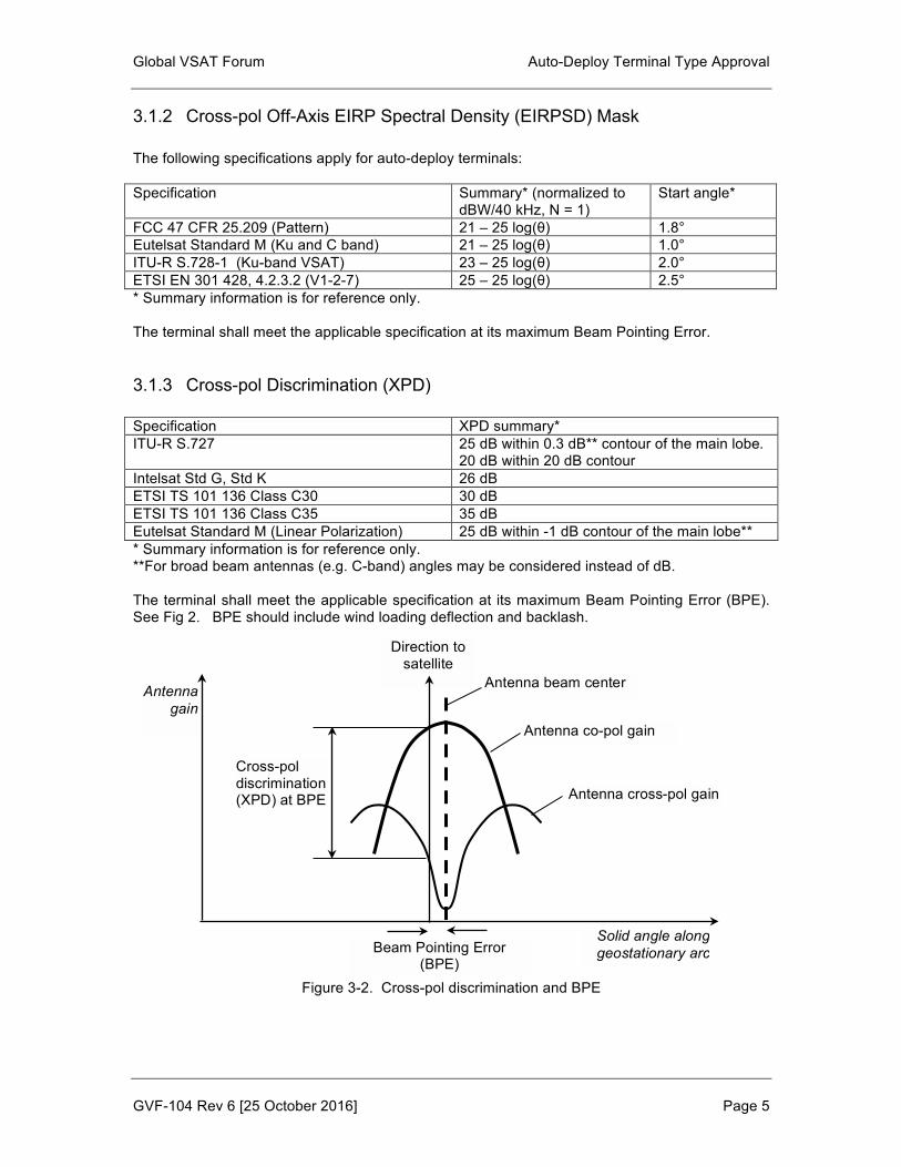
3.1.2 Cross-pol Off-Axis EIRP Spectral Density (EIRPSD) Mask The following specifications apply for auto-deploy terminals: Specification Summary* (normalized to
dBW/40 kHz, N = 1) Start angle*
FCC 47 CFR 25.209 (Pattern) 21 – 25 log(θ) 1.8° Eutelsat Standard M (Ku and C band) 21 – 25 log(θ) 1.0° ITU-R S.728-1 (Ku-band VSAT) 23 – 25 log(θ) 2.0° ETSI EN 301 428, 4.2.3.2 (V1-2-7) 25 – 25 log(θ) 2.5° * Summary information is for reference only. The terminal shall meet the applicable specification at its maximum Beam Pointing Error.
3.1.3 Cross-pol Discrimination (XPD) Specification XPD summary* ITU-R S.727 25 dB within 0.3 dB** contour of the main lobe.
20 dB within 20 dB contour Intelsat Std G, Std K 26 dB ETSI TS 101 136 Class C30 30 dB ETSI TS 101 136 Class C35 35 dB Eutelsat Standard M (Linear Polarization) 25 dB within -1 dB contour of the main lobe** * Summary information is for reference only. **For broad beam antennas (e.g. C-band) angles may be considered instead of dB. The terminal shall meet the applicable specification at its maximum Beam Pointing Error (BPE). See Fig 2. BPE should include wind loading deflection and backlash.
Figure 3-2. Cross-pol discrimination and BPE
Antenna beam center
Direction to satellite
Beam Pointing Error (BPE)
Solid angle along geostationary arc
Antenna gain
Antenna co-pol gain
Antenna cross-pol gain
Cross-pol discrimination (XPD) at BPE

Global VSAT Forum Auto-Deploy Terminal Type Approval
GVF-104 Rev 6 [25 October 2016] Page 6
3.2 Ka-band Antenna Pattern Performance
3.2.1 Co-pol Off-Axis EIRP Spectral Density (EIRPSD) Mask The following specifications apply for auto-deploy terminals: Specification Summary* (normalized
to dBW/40 kHz, N = 1) Start angle*
FCC 47 CFR 25.138 (Power); FCC 47 CFR 25.209 (Pattern); 18.5 – 25 log(θ) 2.0°
1.5° Eutelsat Standard M (HB6) Eutelsat Standard M (Ka Sat)
19 – 25 log(θ) 15 – 25 log(θ) 1.0° (α)
UK OFCOM Licensing Procedures Manual For Satellite (Transportable Earth Station) Applications – ITU RR 22.26-22.39
28 – 25 log(θ) 3.0°
ITU-R S.524-8 (Ka-band) 19 – 25 log(θ) 2.0° ETSI EN 301 360, 4.2.4.2 (V1-2-1) 19 – 25 log(θ) 1.8° * Summary information is for reference only. The terminal shall meet the applicable specification at its maximum Beam Pointing Error. See Fig 1.
Figure 3-3. Off-axis EIRP spectral density and BPE
25log(θ) specification
Antenna beam center
Direction to satellite
Terminal EIRP spectral density
Solid angle along geostationary arc
EIRP spectral density
Beam Pointing Error (BPE)
Global VSAT Forum Auto-Deploy Terminal Type Approval
GVF-104 Rev 6 [25 October 2016] Page 7
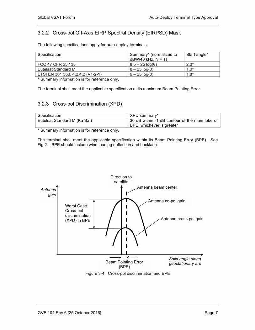
3.2.2 Cross-pol Off-Axis EIRP Spectral Density (EIRPSD) Mask The following specifications apply for auto-deploy terminals: Specification Summary* (normalized to
dBW/40 kHz, N = 1) Start angle*
FCC 47 CFR 25.138 8.5 – 25 log(θ) 2.0° Eutelsat Standard M 8 – 25 log(θ) 1.0° ETSI EN 301 360, 4.2.4.2 (V1-2-1) 9 – 25 log(θ) 1.8° * Summary information is for reference only. The terminal shall meet the applicable specification at its maximum Beam Pointing Error.
3.2.3 Cross-pol Discrimination (XPD) Specification XPD summary* Eutelsat Standard M (Ka Sat) 30 dB within -1 dB contour of the main lobe or
BPE, whichever is greater * Summary information is for reference only. The terminal shall meet the applicable specification within its Beam Pointing Error (BPE). See Fig 2. BPE should include wind loading deflection and backlash.
Figure 3-4. Cross-pol discrimination and BPE
Antenna beam center
Direction to satellite
Beam Pointing Error (BPE)
Solid angle along geostationary arc
Antenna gain
Antenna co-pol gain
Antenna cross-pol gain
Worst Case Cross-pol discrimination (XPD) in BPE
Global VSAT Forum Auto-Deploy Terminal Type Approval
GVF-104 Rev 6 [25 October 2016] Page 8
3.3 Antenna Pointing Accuracy Note: The following recommendations are assumed to reflect the intent of FCC ESV and other regulatory mobile earth station specifications. Specific references are needed. In normal clear-sky operation, the terminal shall not exceed the specified maximum off-axis co-pol EIRPSD, cross-pol EIRPSD, and XPD. This requirement shall apply under all conditions except during the first 500 ms of a transient event. A transient event is defined as any disturbance to the antenna pointing and/or uplink power. It may include events such as wind gusts, vehicle rocking, movement of the antenna base, satellite acquisition, re-peaking, During a transient event, the off-axis co-pol and cross-pol EIRPSD may exceed the specification by up to 6 dB. The terminal shall automatically detect a transient event (as a minimum pitch and roll) and if necessary adjust transmit power or cease transmitting in order to remain compliant with the off-axis EIRPSD mask. EIRPSD co-pol and cross-pol mask may be exceeded during a rain fade by the amount of loss in the path at the transmit frequency. For this reason tests should preferably take place in clear sky conditions.

Global VSAT Forum Auto-Deploy Terminal Type Approval
GVF-104 Rev 6 [25 October 2016] Page 9
4 Type Approval Test Requirements
4.1 Pre-defined parameters The manufacturer or type approval applicant must propose the following parameters that define the terminal’s limits for performance specification compliance:
1) Terminal’s rated maximum on-axis EIRP spectral density (EIRPSD). This should include some margin for transmitter chain gain variation, EIRP stability, etc. It should also include enough margins for the terminal to meet EIRPSD limits at its maximum BPE. EIRPSD should be controlled so it is never exceeded.
2) Rating for minimum detected transient BPE. For example, a terminal may be rated to
recognize a transient angular deflection as low as 0.2 degrees. Certain terminals may have the additional capability of automatically compensating transient angular deflections, provoked by external influences (e.g. wind load, step transients).
3) For highly elliptical antennas which do not rotate to align along the arc or if the rotation is
not performed optimally, the equivalent beam width of the main lobe along the arc could be wider, thus potentially increasing the risk of interference to adjacent satellites.
4) Speed and/or step size for antenna up/down (elevation) and left/right (azimuth) motion.
4.2 Required Tests Tests shall include:
1) Antenna patterns;
2) All pointing error contributors – initial pointing, backlash, deflection under wind load;
3) Pointing accuracy repeatability satellite-to-satellite. Since antennas may be on fixed networks, pointing to user satellite from stow condition is to be considered. At least two different satellites should be used to assess the performance of the antenna control system in different operational conditions (e.g. different satellite polarization’s skew angles);
4) Confirm that transmission does not take place until modem shows lock conditions.
Confirm that if modem is out of lock, transmission is inhibited within 500 msec;
5) Pointing accuracy repeatability deploy-stow-deploy;
6) Pointing error and accuracy repeatability when rotating the antenna assembly with reference to the initial on-ground position;
7) Pointing accuracy and EIRP during simulated rain fade. (wet cloth over feed; look for
increased power level and erroneous pointing deviations);
8) Transient event response. Induce a transient rotation of the antenna base by the rated BPE; measure change in pointing angle and transmit power vs. time. Repeat for all three orthogonal angles;

Global VSAT Forum Auto-Deploy Terminal Type Approval
GVF-104 Rev 6 [25 October 2016] Page 10
9) Transient event response. Induce a transient rotation of the antenna base by angular values higher than the BPE and assess/measure the antenna performance ( stow, mute transmission or reduce power);
10) In case of terminals equipped with automatic compensation of transient angular
deflections, induce a step transient sufficient to cause a deflection by >2.0 degrees (e.g. putting a load on a vehicle mounted antenna) and verify the pointing accuracy response;
11) XPD repeatability satellite-to-satellite;
12) XPD repeatability deploy-stow-deploy;
13) G/T (measured or calculated using nominal values);
14) Other tests as defined in GVF-101 (VSAT level).
The type approval should be conditioned to proof provided by the manufacturer that the performance of the auto-deploy terminal is not affected by wear and tear on mechanical components and antenna optics.
4.3 Test Methods Calibration: To make the tests prescribed above, the terminal must be calibrated to establish a relationship between power and modulation settings, and on-axis EIRPSD, based on the RF antenna performance. Pointing accuracy repeatability test method (concept): attach laser pointer to antenna and aim towards a graph paper target(s) when the antenna is pointed and peaked at the satellite(s). Mark laser spots as pointing accuracy tests are performed. Test should incorporate methods for assessing backlash and wind deflection. To complement to the laser pointer method, the signal level may be measured at the NOC or reference station. When coordinating the tests, once the auto-pointing is completed, the antenna can be manually slewed in azimuth and elevation to find, with the support of the NOC, the maximum peak signal and then from the difference in the values of the Az and El position calculate the pointing error. The manufacturer needs to ensure that the measurement accuracy is sufficient to provide accurate measurements. Similar measurements may be performed for the cross-polarization discrimination, with the NOC or reference station guiding the operator through a manual nulling of the crosspolar and assessing the resulting error of crosspol nulling with respect to auto-pointing.
Global VSAT Forum Auto-Deploy Terminal Type Approval
GVF-104 Rev 6 [25 October 2016] Page 11
A. Appendix: Background Notes
1. The GVF Auto-Deploy Type Approval Initiative
Technology has now become available to provide true broadband satellite communications services from remote locations on a transportable basis and while moving on Land Mobile platforms. The temporary-fixed applications employing auto-deploy, VSAT hardware have proven to be in high demand for military communicators as well as for other users who operate in remote locations like Oil & Gas exploration companies, Emergency First-Responders, and others. The broadband Land Mobile terminals go by various names but the term increasingly in use by the international regulatory community is “Vehicle Mounted Earth Stations”, or “VMES”. Major objectives of these new classes of Earth Stations, which are finding very broad applications in FSS Ku-Band, are that they are supposed to require little or no operator training. Most such terminals are actually being used by operators that have no training in their operation or maintenance whatsoever. With this being the case, the Earth Stations either have to function flawlessly or interference to other FSS users and networks may occur. Not all such Earth Stations are “created equal” and some have demonstrated very repeatable, reliable performance, while others have experienced difficulty pointing accurately towards the desired satellite. There have been incidents where some of these terminals actually acquired satellites several degrees away from the intended orbital location and transmitted for hours or days before being corrected. In some cases, users on the “distant end” of these links were unable to see the downlink so the transmitter power was simply increased to the maximum possible output level, causing extensive interference to unintended victims on completely different satellites. Other frequent incidents relate to interference to the services carried on orthogonal polarized transponders, due to poor polarization alignment algorithms and/or antenna performance. Such irresponsible operation severely reduces the performance and value of the communications link and, potentially, other networks on the same and adjacent satellites. To maintain the value of critical FSS services, it is imperative that the satellite communications industry develop a workable solution to provide for the use of these new classes of satellite communications Earth Stations. Users are demanding their deployment and they are transmitting on more satellites every day, with or without an orderly methodology or standard. Only with an industry-wide solution can FSS satellite communications users be assured of the reliable services they have come to expect. The VMES regulations recently ordered by the United States Federal Communications Commission (FCC) – and those currently being considered in Europe – are a good example of what can be done, but even there, one can see that Regulators are leaving much of the approach to equipment designers and system operators. The VMES regulations prescribe critical antenna pointing accuracy requirements combined with EIRP spectral density limits which are carefully crafted to protect services carried on orthogonal polarized transponders and/or adjacent satellites. The FCC mandates that those standards must be simultaneously met. It is left to manufacturers to determine how to design systems to meet those standards and how to demonstrate that the expected level of performance is being achieved. The FCC clearly expects the industry to rise to the challenge and make maximum use of the newly-granted privileges without having regulated a technology-specific technology, approach, or limitation. Accordingly, the GVF has been called upon by the industry to facilitate industry-wide consensus on the harmonization of test procedures and acceptance criteria in standards, on a global basis, for the design and operation of such terminals. Therefore, the GVF plans to establish a consensus among industry participants regarding a suitable level of Performance Validation that will assure continuation of the exceptionally high reliability and value of FSS satellite systems.
Global VSAT Forum Auto-Deploy Terminal Type Approval
GVF-104 Rev 6 [25 October 2016] Page 12
The GVF, through the MRA process, plans to follow the road-map which has been successfully implemented for the FSS VSAT Industry. This process calls for an independent evaluation of a manufacturer’s product design, manufacturing procedures and performance against SSP specifications culminating with a formal type approval. The independent objectivity of the design, manufacturing and test program is such that the test results are recognized by multiple satellite operators. This process ensures that only compliant, performance-proven designs are deployed in the marketplace, thereby eliminating problems that cause interference to adjacent satellites and to transponders on the intended satellite. As a subordinate objective, the GVF will work with participating satellite operators to harmonize ground equipment performance specifications in two or three tier standards based on the ground equipment performance capabilities. The GVF looks forward to working with industry, satellite service providers and regulatory agencies to facilitate the introduction of qualified equipment in to the developing auto-deploy VSAT market.
2. Off-axis EIRP Spectral Density Regulations The provisions of ITU-R S.524-9 (or the most current version thereof) shall set the maximum permissible off-axis EIRP limits. Regional or national limits may modify the provisions of ITU-R S.524.9 providing that they do not exceed the recommended EIRP limits in any direction. The radiation pattern characteristics of all auto-deploy and VMES antenna systems are expected to comply with the most current requirements of ITU-R S.580 or those in force for a particular geographic or national region providing that the EIRP density does not exceed the limits of ITU-R S.580. Terminals failing to meet the requirements of ITU-R S.580 (or those of local regulatory limitations) may be authorized by limiting the input power to the terminal such that its up-link EIRP density does not exceed the limits of ITU-R S.524 (or local regulatory limit) in any direction. A2.1 Notes and excerpts from ITU-R S.524-9 for Ku-Band FSS Operation Operation in this band shall be confined to the 12.75 – 13.25 GHz for the satellite to earth path and 13.75 – 14.50 GHz for earth to satellite link. Certain satellite operators require different satellite to earth path frequency ranges (i.e. for Eutelsat: 11.7 -12.75 GHz; Star One: 10.9-12.2 GHz) The uplink EIPR shall be restricted such EIRP density in any direction along the GSO does not exceed the following values. Angular Range Maximum EIPR per 40 kHz 2.5 <= θ <= 7.0 deg 39 – 25 log (θ) dBW / 40 kHz 7.0 < θ <= 9.2 deg 18 dBW / 40 kHz 9.2 < θ <= 48 deg 42 – 25 log (θ) dBW / 40 kHz 48 < θ <= 180 deg 0 dBW / 40 kHz
A2.2 Notes and excerpts from FCC regulations Until recently the FCC did not establish an off-axis EIRP mask in the same way as specified by the provisions of ITU-R S.524. Rather the FCC set limits on the input power to the antenna flange and the off-axis radiation characteristics for the antenna under consideration. The combination of these two requirements effectively set the off-axis EIRP radiation levels. Recently FCC Eight Order resulted on a new ruling 47 CFR 25.218 which combined the provisions of 47 CFR 25.212 and 47 CFR 25.209 to establish an off-axis EIRP mask which
Global VSAT Forum Auto-Deploy Terminal Type Approval
GVF-104 Rev 6 [25 October 2016] Page 13
extended from 1.5 degrees to 7 degrees. Thus the key provisions of FCC requirements for narrow Ku-band transmissions can be summarized by the following: A2.2.1 FCC sidelobe mask (47 CFR 25.209) The antenna gain for a compliant antenna shall not exceed the following limits over the defined angular limits Angular Range Maximum gain 1.0 deg <= (θ) <= 7.0 deg 29 – 25 log (θ) dBi 7.0 deg <= (θ) <= 9.2 deg + 8 dBi 9.2 deg <= (θ) <= 48.0 deg 32 – 25 log (θ) dBi 48. deg <= (θ) <= 180. deg - 10 dBi The close in sidelobe mask for small antennas (1.2 meters) is increased to start at 1.25 degrees than 1.0 degrees. A2.2.3 Input power limitations, Narrowband Ku-band transmissions (46 C.F.R. 25.212) The power density presented to the antenna input flange shall not exceed -14 dBW / 4 kHz for narrow band transmissions. This equates to -4 dBW / 40 kHz when comparing with the ITU bandwidth designations. A2.2.3 FCC New Eighth Report and Order (47 C.F.R. 25.218) This rule expanded the starting angle for the initial 29 – 25 log (θ) mask to 1.5 degrees. The rule also set the EIRP density limit over the angular range from 1.5 deg <= (θ) <= 7 deg to a maximum EIRP of 15 – 25 log(θ) dBW / 4 kHz. This equates to an EIRP density of 25 – 25 log(θ) dBW / 40 kHz when comparing with the ITU bandwidth designations. If antenna does not meet 29-25 log(θ) then power density at the antenna flange shall be reduced such that the radiated EIRP complies with the 15-25 log(θ) dBw/4kHz limit from 1.5deg < θ < 7deg. A2.2.4 FCC ESV regulation (47 C.F.R. 25.222) This rule was created for Ku-band VSATs on ships (vessels) using stabilized antennas. It essentially follows the combination of 25.209 (antenna pattern) with 25.212 (transmitter power spectral density) to give a net off-axis EIRP spectral density mask of 15 – 25log(θ) dBW per 4 kHz, starting at 1.25 degrees. It also requires that the antenna have a maximum pointing error of 0.2 degrees, cease transmission within 100 ms if the pointing error exceeds 0.5 degrees, and not resume transmission until the error returns to less than 0.2 degrees. A2.3 Notes on UK OFCOM regulations The U.K. Office of Communications has utilized the ITU requirements to set limits for the antenna radiation pattern coverage and off-axis EIRP limits. The antenna radiation pattern is required to comply with the provisions of ITU-R S.465 or ITU-R S.580 for antennas installed after 1995. The off-axis EIRP power density mask is required to comply with the provisions of ITU-R S.524-9. Mobile stations shall employ a stabilised platform with the ability to maintain a pointing accuracy +/–0.2 degrees towards the relevant Geostationary Satellite throughout transmissions. In addition, the maximum EIRP at angles greater than or equal to 2.5 degrees from the antenna main beam axis shall not exceed 20 dBW/40 kHz from any individual station. A2.4 Notes on Eutelsat regulations
Global VSAT Forum Auto-Deploy Terminal Type Approval
GVF-104 Rev 6 [25 October 2016] Page 14
Eutelsat specification EESS 502 Standard M specifies Off-Axis EIRP Density for different bands and specific satellites. E.g.: 29 – 25 log (θ) dBW/40 kHz for extended Ku-band (13.75 – 14.0 GHz) 19 – 25 log (θ) dBW/40 kHz for Eutelsat 8 West C in Ka-band 19 – 25 log (θ) dBW/40 kHz for Ka Sat
Global VSAT Forum Auto-Deploy Terminal Type Approval
GVF-104 Rev 6 [25 October 2016] Page 15
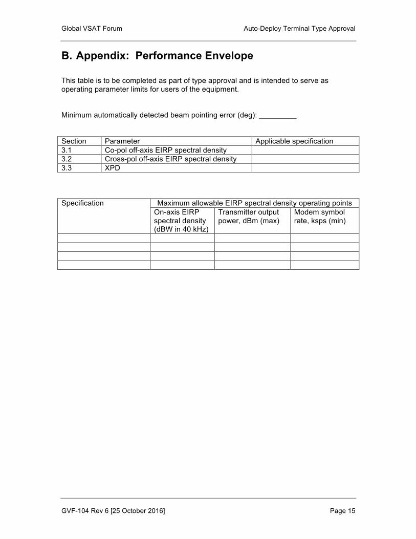
B. Appendix: Performance Envelope This table is to be completed as part of type approval and is intended to serve as operating parameter limits for users of the equipment. Minimum automatically detected beam pointing error (deg): _________ Section Parameter Applicable specification 3.1 Co-pol off-axis EIRP spectral density 3.2 Cross-pol off-axis EIRP spectral density 3.3 XPD Specification Maximum allowable EIRP spectral density operating points
On-axis EIRP spectral density (dBW in 40 kHz)
Transmitter output power, dBm (max)
Modem symbol rate, ksps (min)

Global VSAT Forum Auto-Deploy Terminal Type Approval
GVF-104 Rev 6 [25 October 2016] Page 16
Global VSAT Forum
AUTO-DEPLOY TYPE APPROVAL: STEP-BY-STEP PROCEDURES Prepared by Fulvio Fresia. [15 Feb, 2013]
ADDENDUM GVF-104
This document defines the applicable performance requirements and test procedures for GVF Type Approval of Auto-Deploy and Vehicle Mounted Earth Station (VMES) VSAT communications antenna systems.

Global VSAT Forum Auto-Deploy Terminal Type Approval
GVF-104 Rev 6 [25 October 2016] Page 17
5 Step-by-Step Procedures
The GVF representative and the operator of the SUT meet at the test site, and review the step by step procedure.
Principle of the tests The GRS (GVF Reference Station), through its antenna, monitors the signal transmitted from the SUT.
After auto-deploy completed, the GRS instructs the SUT to optimize (driving manually the motors of the auto-deploy terminal) the position of the antenna (Azimuth, Elevation) until maximizing the monitored signal. Then GRS instructs SUT to optimize the polarization (driving manually the polarization motor) until the cross-polar component of the monitored signal is minimized. To perform these tests the GRS shall ensure that the same frequency slots in the co-polar and cross-polar transponders are available. To be able to minimize the cross-polar component, the GRS antenna must have a receive gain sufficient for detecting small signal out of the spectrum analyzer noise floor.
The test results will be based on the readouts of Azimuth, Elevation and Polarization available at SUT.
The following methods to obtain the pointing data can be used:
§ SUT’s own resolvers readouts,
§ Laser beam indications, § External positioner encoders.
If the SUT is mounted on an external positioner of the test range, the Azimuth and Elevation readouts of the test range will be used throughout the tests, if possible. SUT and GVF representative will discuss which readout should be utilized for the polarization angle.
If the SUT is using its own positioner, the GVF representative and SUT’s operator discuss the resolvers’ resolution and decide whether they are sufficient for the scope of the tests. In case they were not, the laser beam method (see Annex E) will be used.
Definitions The abbreviations “AAZ”, “AEL”, “APOL”, “AXPD” and “AEIRP” represent the respective values (azimuth, elevation, polarization angle, XPD (Cross-Polarization Discrimination) and EIRP) achieved when deploying the antenna automatically.
“MAZ”, “MEL”, “MPOL”, “MXPD” and “MEIRP” are the values after manual optimization.
Step 1 SUT establishes a telephone call with the GRS (GVF Reference Station),
review the GVF test plan and the following check list:
General check list
¨ Satellite orbital position, polarization, transmit and receive frequencies, polarizations,
¨ Azimuth slew speed, ¨ Elevation slew speed,

Global VSAT Forum Auto-Deploy Terminal Type Approval
GVF-104 Rev 6 [25 October 2016] Page 18
¨ Polarizer rotational speed, ¨ Possibility to transmit a CW carrier, ¨ Weather and wind conditions at SUT and at GRS,
¨ Geostationary arc visibility, ¨ Carrier (Beacon, DVB-S2, Hub carrier etc) or method (NORAD
etc) used to achieve the auto-pointing process, ¨ Transmit RF Carrier monitoring system (type, manufacturer,
model),
¨ Transmit coupling factor, ¨ Post-coupler loss.
Step 2 For reflectors with petals, assemble the reflector under control of the GVF
representative.
Step 3 The GVF representative will review the monitoring tools available at SUT and ensure that no transmission is possible prior to the completion of the auto-deploy process.
Ensure that the auto-deploy terminal start from STOW position. On instruction from GRS, SUT will enable the auto-deploy function. The GVF representative will measure the elapsed time from STOW to the completion of the Auto-deploy process.
If the auto-deploy process does not complete, repeat the process once again. If it still fails, the GVF representative, GRS and SUT will decide if tests can continue with a different position of the auto-deploy terminal or a different satellite or tests need to be cancelled.
If the auto-deploy process completes, confirm that the SUT is correctly pointed on the satellite and with the correct polarization, by verifying reception of a test carrier transmitted from GRS.
IMPORTANT: In case of doubts at SUT on the satellite being pointed, GRS will switch on and off few times its test carrier and SUT’s operator will monitor it to ensure that the auto-deploy terminal is pointed on the targeted satellite.
DO NOT PROCEED TO STEP 4 UNTIL THIS IS CONFIRMED.
Step 4 In coordination with GRS, SUT will transmit a CW carrier, at a frequency and eirp determined in the test plan. The CW will be power balanced by the GRS (as an example cfr. procedure in ESOG Vol. 1 Section 4.3 Module 130). Report in table C1 and in table D2 the relevant test parameters and SUT configuration.
Step 5 AZIMUTH OPTIMIZATION Ensure that the antenna is still in the position reached at the end of the auto-deploy process, record the auto-deploy terminal’s AAZ, AEL and APOL. The GRS will calculate and communicate to the SUT the value of AEIRP and AXPD.
Disable all satellite tracking functions, ensure that the SUT will not automatically re-adjust its pointing and under co-ordination of the GRS and the GVF representative, carefully slew a step at a time the antenna Azimuth Right until the position AAZ+2°. GRS will monitor the variation of
Global VSAT Forum Auto-Deploy Terminal Type Approval
GVF-104 Rev 6 [25 October 2016] Page 19
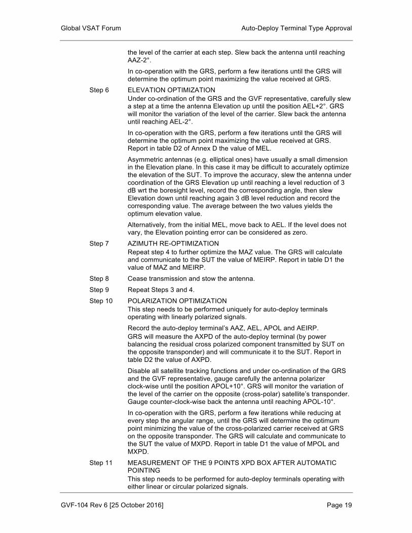
the level of the carrier at each step. Slew back the antenna until reaching AAZ-2°.
In co-operation with the GRS, perform a few iterations until the GRS will determine the optimum point maximizing the value received at GRS.
Step 6 ELEVATION OPTIMIZATION Under co-ordination of the GRS and the GVF representative, carefully slew a step at a time the antenna Elevation up until the position AEL+2°. GRS will monitor the variation of the level of the carrier. Slew back the antenna until reaching AEL-2°.
In co-operation with the GRS, perform a few iterations until the GRS will determine the optimum point maximizing the value received at GRS. Report in table D2 of Annex D the value of MEL.
Asymmetric antennas (e.g. elliptical ones) have usually a small dimension in the Elevation plane. In this case it may be difficult to accurately optimize the elevation of the SUT. To improve the accuracy, slew the antenna under coordination of the GRS Elevation up until reaching a level reduction of 3 dB wrt the boresight level, record the corresponding angle, then slew Elevation down until reaching again 3 dB level reduction and record the corresponding value. The average between the two values yields the optimum elevation value.
Alternatively, from the initial MEL, move back to AEL. If the level does not vary, the Elevation pointing error can be considered as zero.
Step 7 AZIMUTH RE-OPTIMIZATION Repeat step 4 to further optimize the MAZ value. The GRS will calculate and communicate to the SUT the value of MEIRP. Report in table D1 the value of MAZ and MEIRP.
Step 8 Cease transmission and stow the antenna.
Step 9 Repeat Steps 3 and 4.
Step 10 POLARIZATION OPTIMIZATION This step needs to be performed uniquely for auto-deploy terminals operating with linearly polarized signals.
Record the auto-deploy terminal’s AAZ, AEL, APOL and AEIRP. GRS will measure the AXPD of the auto-deploy terminal (by power balancing the residual cross polarized component transmitted by SUT on the opposite transponder) and will communicate it to the SUT. Report in table D2 the value of AXPD.
Disable all satellite tracking functions and under co-ordination of the GRS and the GVF representative, gauge carefully the antenna polarizer clock-wise until the position APOL+10°. GRS will monitor the variation of the level of the carrier on the opposite (cross-polar) satellite’s transponder. Gauge counter-clock-wise back the antenna until reaching APOL-10°.
In co-operation with the GRS, perform a few iterations while reducing at every step the angular range, until the GRS will determine the optimum point minimizing the value of the cross-polarized carrier received at GRS on the opposite transponder. The GRS will calculate and communicate to the SUT the value of MXPD. Report in table D1 the value of MPOL and MXPD.
Step 11 MEASUREMENT OF THE 9 POINTS XPD BOX AFTER AUTOMATIC POINTING This step needs to be performed for auto-deploy terminals operating with either linear or circular polarized signals.

Global VSAT Forum Auto-Deploy Terminal Type Approval
GVF-104 Rev 6 [25 October 2016] Page 20
The XPD is evaluated within a cone centred on the main beam axis, with the cone defined by the pointing error or the - 1dB contour of the main beam axis, whichever is greater.
Cease transmission, stow the antenna and repeat Steps 3 and 4. Record the auto-deploy terminal’s AAZ, AEL, APOL and AEIRP. Repeat steps 5 to 7 (Azimuth and Elevation optimization).
Disable all satellite tracking functions and under co-ordination of the GRS and the GVF representative, perform the 9 points XPD box verification starting from the APOL initial value.
An example of the procedure for the 9 points XPD box verification is shown in the ESOG Vol. 1 Section 7 Module 130.
It is recommended in addition to the 9 points to measure 4 additional points, corresponding to the -1 dB contour on the Azimuth left and right and Elevation up and down planes.
In case that the ΔAZ= AAZ-MAZ and/or ΔEL=AEL-MEL were greater than the angles corresponding to the -1 dB contour of the main lobe, the 9 and 4 points shall be verified taking into account the overall de-pointing angle rather than the angles corresponding to the -1 dB contour.
Report in table D3.1 and D3.2 of Annex D the corresponding measured XPD values.
Step 12 Cease transmission and stow the auto-deploy terminal. For antennas with petals, disassemble the antenna.
Step 13 Repeat tests 2 to 11 for the other polarization.
Step 14 AUTO-DEPLOY TESTS ON TILTED TERMINAL Move the auto-deploy terminal in such a way that there will be an angle δ of at least 5° (or higher, depending on the auto-deploy terminal maximum tilt specification) formed by the auto-deploy terminal wrt a level ground. In case of a vehicle-mounted auto-deploy terminal, insert a wedge under one or more of the tires of the vehicle.
Repeat steps 2 to 13. Step 15 AUTO-DEPLOY TESTS WITH DIFFERENT ORIENTATION OF THE
AUTO-DEPLOY TERMINAL WRT THE SATELLITE Under co-ordination of the GVF representative, change the ground orientation of the auto-deploy terminal (or the position of it on the positioner of the test range) wrt the satellite of at least 60° in Azimuth.
Repeat steps 2 to 13.
Step 16 AUTO-DEPLOY TESTS ON A SATELLITE AT A DIFFERENT ORBITAL LOCATION To make sure that the auto-deploy terminal performance is maintained irrespective of the satellite being accessed, the GVF test plan will normally require repeating the auto-deploy tests on a second and possibly third satellite, at a different orbital location.
Repeat step 1 to 15 for a new satellite at a different orbital position. NOTE: Use of inclined orbit satellites should be avoided for auto-deploy terminals
not equipped with tracking sub-system.
TEST RESULTS
At the end of each test session, for a given satellite and polarization, SUT’s operators and the GVF representative will fill in and sign the test results summary sheets.

Global VSAT Forum Auto-Deploy Terminal Type Approval
GVF-104 Rev 6 [25 October 2016] Page 21
Global VSAT Forum Auto-Deploy Terminal Type Approval
GVF-104 Rev 6 [25 October 2016] Page 22
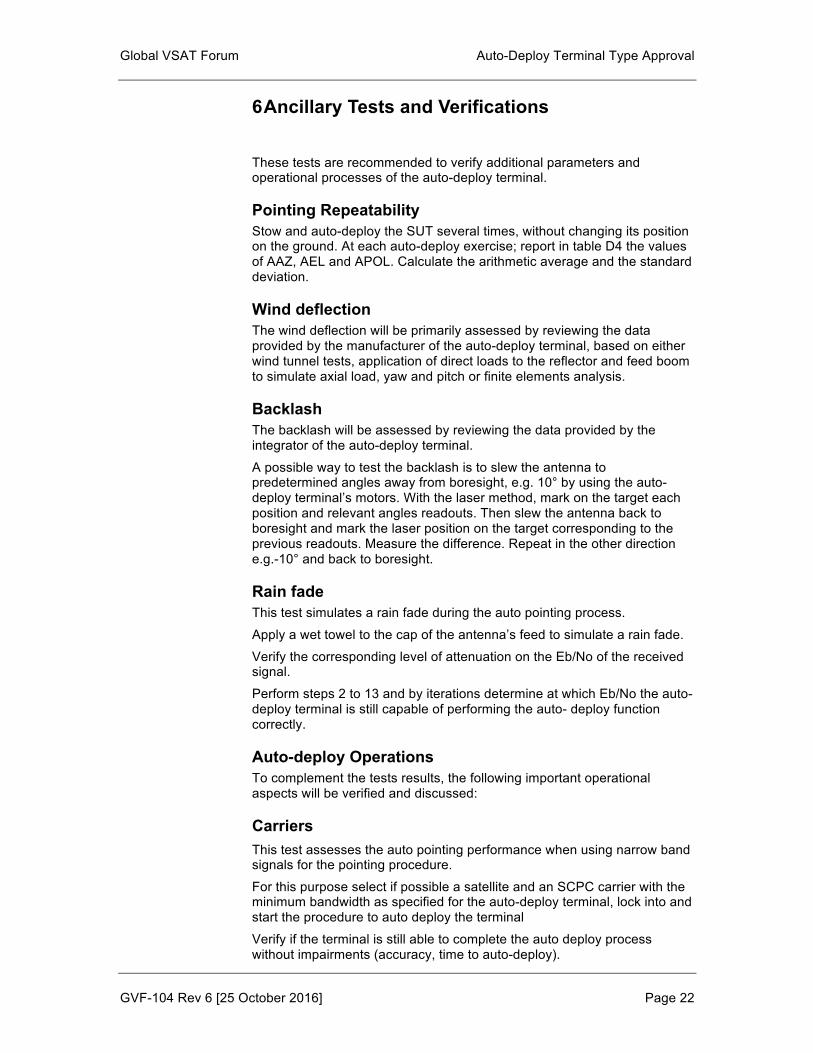
6 Ancillary Tests and Verifications These tests are recommended to verify additional parameters and operational processes of the auto-deploy terminal.
Pointing Repeatability Stow and auto-deploy the SUT several times, without changing its position on the ground. At each auto-deploy exercise; report in table D4 the values of AAZ, AEL and APOL. Calculate the arithmetic average and the standard deviation.
Wind deflection The wind deflection will be primarily assessed by reviewing the data provided by the manufacturer of the auto-deploy terminal, based on either wind tunnel tests, application of direct loads to the reflector and feed boom to simulate axial load, yaw and pitch or finite elements analysis.
Backlash The backlash will be assessed by reviewing the data provided by the integrator of the auto-deploy terminal.
A possible way to test the backlash is to slew the antenna to predetermined angles away from boresight, e.g. 10° by using the auto-deploy terminal’s motors. With the laser method, mark on the target each position and relevant angles readouts. Then slew the antenna back to boresight and mark the laser position on the target corresponding to the previous readouts. Measure the difference. Repeat in the other direction e.g.-10° and back to boresight.
Rain fade This test simulates a rain fade during the auto pointing process.
Apply a wet towel to the cap of the antenna’s feed to simulate a rain fade.
Verify the corresponding level of attenuation on the Eb/No of the received signal.
Perform steps 2 to 13 and by iterations determine at which Eb/No the auto-deploy terminal is still capable of performing the auto- deploy function correctly.
Auto-deploy Operations To complement the tests results, the following important operational aspects will be verified and discussed:
Carriers This test assesses the auto pointing performance when using narrow band signals for the pointing procedure.
For this purpose select if possible a satellite and an SCPC carrier with the minimum bandwidth as specified for the auto-deploy terminal, lock into and start the procedure to auto deploy the terminal
Verify if the terminal is still able to complete the auto deploy process without impairments (accuracy, time to auto-deploy).
Global VSAT Forum Auto-Deploy Terminal Type Approval
GVF-104 Rev 6 [25 October 2016] Page 23
Transmit enable Verify that it is not possible for the operator to enable transmission of a carrier until the auto-deploy process. In case this was possible, verify that a warning message is issued to the operator.
Transmit cease Verify the time needed in order to interrupt the auto-pointing process when the operator ceases the auto-pointing operations. Verify that no carrier is transmitted.
Global VSAT Forum Auto-Deploy Terminal Type Approval
GVF-104 Rev 6 [25 October 2016] Page 24
Laser beam method procedure ________________ ______________________________________________________________________
.
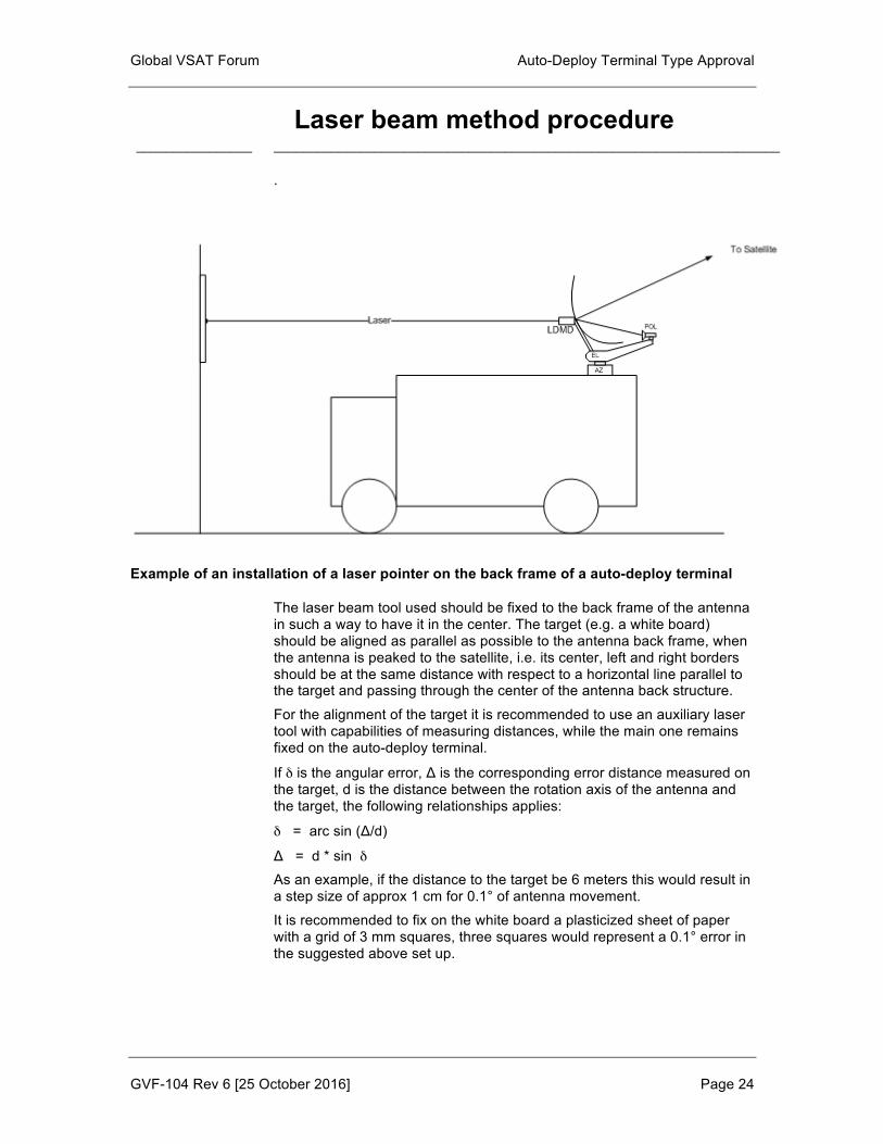
Example of an installation of a laser pointer on the back frame of a auto-deploy terminal
The laser beam tool used should be fixed to the back frame of the antenna in such a way to have it in the center. The target (e.g. a white board) should be aligned as parallel as possible to the antenna back frame, when the antenna is peaked to the satellite, i.e. its center, left and right borders should be at the same distance with respect to a horizontal line parallel to the target and passing through the center of the antenna back structure.
For the alignment of the target it is recommended to use an auxiliary laser tool with capabilities of measuring distances, while the main one remains fixed on the auto-deploy terminal.
If δ is the angular error, Δ is the corresponding error distance measured on the target, d is the distance between the rotation axis of the antenna and the target, the following relationships applies:
δ = arc sin (Δ/d)
Δ = d * sin δ As an example, if the distance to the target be 6 meters this would result in a step size of approx 1 cm for 0.1° of antenna movement.
It is recommended to fix on the white board a plasticized sheet of paper with a grid of 3 mm squares, three squares would represent a 0.1° error in the suggested above set up.
Global VSAT Forum Auto-Deploy Terminal Type Approval
GVF-104 Rev 6 [25 October 2016] Page 25
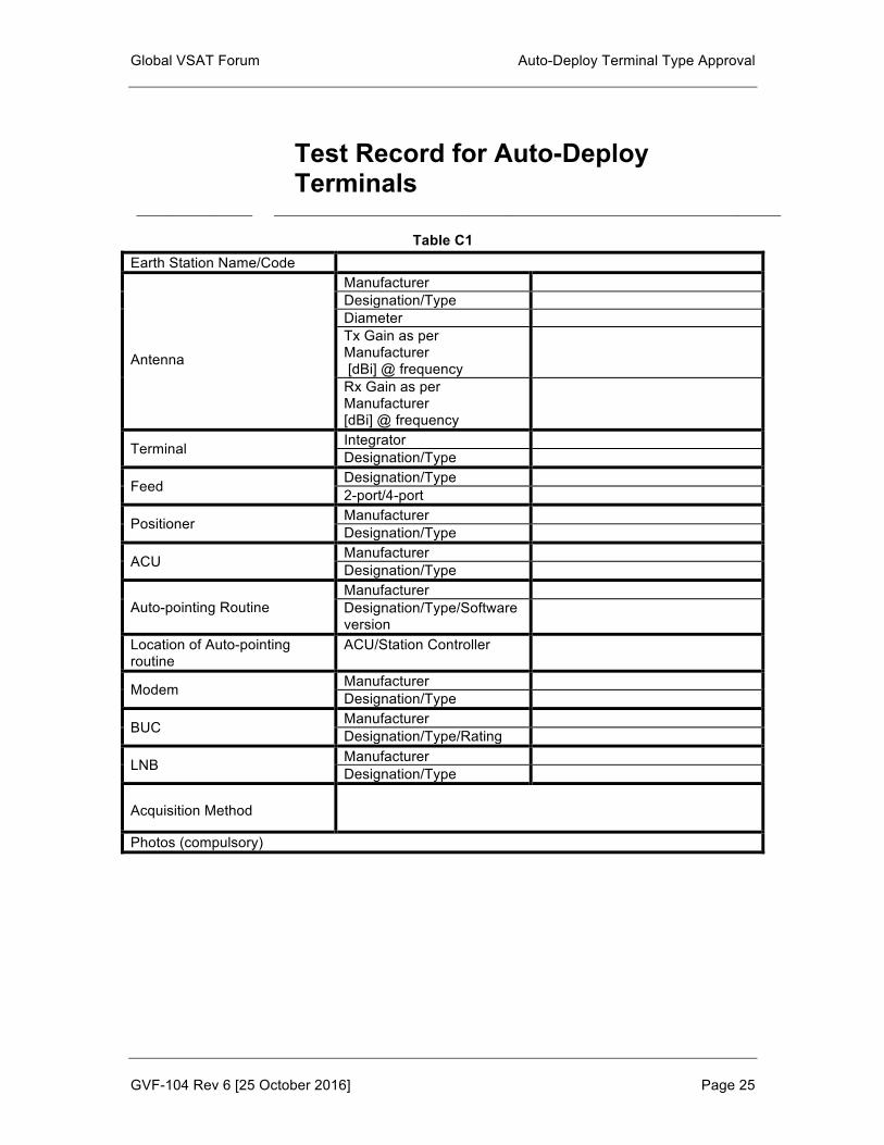
Test Record for Auto-Deploy Terminals
________________ ______________________________________________________________________
Table C1 Earth Station Name/Code
Antenna
Manufacturer Designation/Type Diameter Tx Gain as per Manufacturer [dBi] @ frequency
Rx Gain as per Manufacturer [dBi] @ frequency
Terminal Integrator Designation/Type
Feed Designation/Type 2-port/4-port
Positioner Manufacturer Designation/Type
ACU Manufacturer Designation/Type
Auto-pointing Routine Manufacturer Designation/Type/Software version
Location of Auto-pointing routine
ACU/Station Controller
Modem Manufacturer Designation/Type
BUC Manufacturer Designation/Type/Rating
LNB Manufacturer Designation/Type
Acquisition Method
Photos (compulsory)

Global VSAT Forum Auto-Deploy Terminal Type Approval
GVF-104 Rev 6 [25 October 2016] Page 26
Notes
Date/Record compiled by

Global VSAT Forum Auto-Deploy Terminal Type Approval
GVF-104 Rev 6 [25 October 2016] Page 27
Auto-Deploy Results Summary Sheets
________________ ______________________________________________________________________
Table D1 – Summary of Auto-Deploy Tests Results Steps 1-10
Satellite Identification Orbital Location
Frequency Up/Down [GHz]
Date/Place: Weather SUT/GRS
(*) Does not apply for auto-deploy terminals operating in circular polarization (**) Pol error does not apply for auto-deploy terminals operating in circular polarization
Test ConfN°/ Pol (***)
AAZ [Deg]
AEL [Deg]
APOL [Deg]
AEIRP [dBW]
AXPD [dB]
MAZ [Deg]
MEL [Deg]
MPOL (*) [Deg]
MEIRP [dBW]
MXPD [dB]
ΔAZ,ΔEL, ΔPOL (**) [Deg]
1
2
3
4
5
6
7
8
9
10

Global VSAT Forum Auto-Deploy Terminal Type Approval
GVF-104 Rev 6 [25 October 2016] Page 28
(***) Specify if X/Y or Y/X for linear polarization; LHCP/RHCP or RHCP/LHCP for circular polarization
Provide a separate result’s sheet for each satellite and polarization

Global VSAT Forum Auto-Deploy Terminal Type Approval
GVF-104 Rev 6 [25 October 2016] Page 29
TABLE D2 – Notes on the Test Configurations of Table D1
Test Conf. N°
1
2
3
4
5
6
7
8
9
10
Add test configurations as necessary Date/Record compiled by: Other notes:
Provide a separate sheet for each accessed satellite

Global VSAT Forum Auto-Deploy Terminal Type Approval
GVF-104 Rev 6 [25 October 2016] Page 30
TABLE D3. – 1 - 9 Points-XPD Box AXPD (auto-deploy XPD) results for Terminal - STEP 11
Satellite Identification Orbital Location
Frequency Up/Down [GHz]
Polarization Up/Down Weather SUT/GRS
TABLE D3.2 - Additional 4 Points-box AXPD (auto-deploy XPD) results for Terminal
Test N° Polarization (***) 1 (AZ+) 2 (AZ-) 3 (EL+) 4 (EL-)
1
2
3
4
5
Provide a separate result’s sheet for each satellite and polarization
Test N°
Pola-rization (***)
1
2
3
4
5
6
7
8
9
1
2
3
4
5

Global VSAT Forum Auto-Deploy Terminal Type Approval
GVF-104 Rev 6 [25 October 2016] Page 31
(***) Specify if X/Y or Y/X for linear polarization; LHCP/RHCP or RHCP/LHCP for circular polarization

Global VSAT Forum Auto-Deploy Terminal Type Approval
GVF-104 Rev 6 [25 October 2016] Page 32
TABLE D4 Auto-Deploy Pointing Repeatability for Terminal
Provide a separate result’s sheet for each satellite and polarization (***) Specify if X/Y or Y/X for linear polarization; LHCP/RHCP or RHCP/LHCP for circular
polarization
Troubleshooting Check List ¨ The signal where the terminal shall lock is visible on the
monitoring equipment (e.g. spectrum analyser), ¨ The CW of GRS is visible on the monitoring equipment, ¨ The CW of SUT is transmitted at requested frequency and
polarization, ¨ Modem is locked on the modulated signal prior to
transmission, ¨ If GRS switches off the CW, carrier is not visible any more on
the monitoring equipment.
Attempt N°
Polariz (***)
Azimuth
Elevation
Polarization
1
2
3
4
5