Global Academy of Technology - gat.ac.in · by applying Bernoulli’s theorem AP 3 CO2 Calibrate V...
79
Global Academy of Technology Accredited by NAAC- ‘A’ grade (Approved by AICTE, New Delhi and affiliated to VTU- Belagavi) DEPARTMENT OF CIVIL ENGINEERING LAB MANUAL Student Name : USN : Academic Year : 2018 – 2019 (EVEN SEMESTER) Programme (UG/PG) : UG Year / Semester : II Year/ IV Semester Course Code : 17CVL47 Course Title : FM & HM LABORATORY Prepared By Mrs. Theja S N Assistant Professor Mrs Seema S Assistant Professor
Transcript of Global Academy of Technology - gat.ac.in · by applying Bernoulli’s theorem AP 3 CO2 Calibrate V...
Global Academy of Technology Accredited by NAAC- ‘A’ grade
(Approved by AICTE, New Delhi and affiliated to VTU- Belagavi)
DEPARTMENT OF CIVIL ENGINEERING
LAB MANUAL
Student Name :
USN :
Academic Year : 2018 – 2019 (EVEN SEMESTER)
Programme (UG/PG) : UG
Year / Semester : II Year/ IV Semester
Course Code : 17CVL47
Course Title : FM & HM LABORATORY
Prepared By
Mrs. Theja S N
Assistant Professor
Mrs Seema S
Assistant Professor
Global Academy of Technology Accredited by NAAC- ‘A’ grade
(Approved by AICTE, New Delhi and affiliated to VTU- Belagavi)
LABORATORY CERTIFICATE
This is to certify that Mr. / Ms.
bearing USN 1GA___CV_____ of 4th semester of the DEPARTMENT OF CIVIL ENGINEERING
has satisfactorily completed the experiments under the course of FM & HM LABORATORY
(17CVL47) as prescribed by Visvesvaraya Technological University, Belagavi, in the Laboratory of this
college in the year 2018-2019
Name & Signature of the Course Instructor
Signature of the Head of the Department
DATE:
MARKS
Maximum Obtained
40

Dept. of Civil engineering FM&HM Lab Manual/17CVL47
GLOBAL ACADEMY OF TECHNOLOGY
VISION
Become a premier institution imparting quality education in engineering and
management to meet the changing needs of society
MISSION
M1. Create environment conducive for continuous learning through quality
teaching and learning processes supported by modern infrastructure
M2. Promote Research and Innovation through collaboration with industries
M3. Inculcate ethical values and environmental consciousness through
holistic education programs

Dept. of Civil engineering FM&HM Lab Manual/17CVL47
GLOBAL ACADEMY OF TECHNOLOGY
DEPARTMENT OF CIVIL ENGINEERING
VISION
To be a department with excellent learning & teaching environment for imparting quality
education to students in Civil Engineering to serve the needs of society.
MISSION
M1. To create conducive environment of continuous learning, teaching & improvement
for students & faculty through state-of-the-art infrastructure.
M2. To promote professionalism among students through collaboration with industries.
M3. To inculcate ethical values and environmental consciousness amongst students
through holistic development programs to serve society.
Program Educational Objectives [PEOs]
PEO-1: Employment in government and private organizations
PEO-2: Pursuing higher studies and research
PEO-3: Contribution to the advancement of civil engineering, science and other multi-
disciplinary areas
PEO-4: Entrepreneurship, continuous learning and comply with professional ethics and
environmental requirements

Dept. of Civil engineering FM&HM Lab Manual/17CVL47
GLOBAL ACADEMY OF TECHNOLOGY
PROGRAM OUTCOMES (POs)
Engineering Graduates will be able to:
PO1. Engineering knowledge: Apply the knowledge of mathematics, science,
engineering fundamentals, and an engineering specialization to the solution of complex
engineering problems.
PO2. Problem analysis: Identify, formulate, review research literature, and analyze
complex engineering problems reaching substantiated conclusions using first principles
of mathematics, natural sciences, and engineering sciences.
PO3. Design/development of solutions: Design solutions for complex engineering
problems and design system components or processes that meet the specified needs with
appropriate consideration for the public health and safety, and the cultural, societal, and
environmental considerations.
PO4. Conduct investigations of complex problems: Use research-based knowledge and
research methods including design of experiments, analysis and interpretation of data,
and synthesis of the information to provide valid conclusions.
PO5. Modern tool usage: Create, select, and apply appropriate techniques, resources,
and modern engineering and IT tools including prediction and modeling to complex
engineering activities with an understanding of the limitations.
PO6. The engineer and society: Apply reasoning informed by the contextual knowledge
to assess societal, health, safety, legal and cultural issues and the consequent
responsibilities relevant to the professional engineering practice.
PO7. Environment and sustainability: Understand the impact of the professional
engineering solutions in societal and environmental contexts, and demonstrate the
knowledge of, and need for sustainable development.

Dept. of Civil engineering FM&HM Lab Manual/17CVL47
GLOBAL ACADEMY OF TECHNOLOGY
PO8. Ethics: Apply ethical principles and commit to professional ethics and
responsibilities and norms of the engineering practice.
PO9. Individual and team work: Function effectively as an individual, and as a member
or leader in diverse teams, and in multidisciplinary settings.
PO10. Communication: Communicate effectively on complex engineering activities
with the engineering community and with society at large, such as, being able to
comprehend and write effective reports and design documentation, make effective
presentations, and give and receive clear instructions.
PO11. Project management and finance: Demonstrate knowledge and understanding of
the engineering and management principles and apply these to one’s own work, as a
member and leader in a team, to manage projects and in multidisciplinary environments.
PO12. Life-long learning: Recognize the need for, and have the preparation and ability
to engage in independent and life-long learning in the broadest context of technological
change.
PSO
Upon successful completion, Civil Engineering graduates will be able to:
PSO1. Comprehend, analyze and design alternatives for execution of civil engineering
facilities
PSO2. Apply Standard Codes of Practices and schedule of rates for planning, design,
quality control, estimating and costing of civil engineering projects.
PSO3. Evaluate the buildings for sustainability through minimal utilization of resources
in construction
Dept. of Civil engineering FM&HM Lab Manual/17CVL47
GLOBAL ACADEMY OF TECHNOLOGY
Regulations Governing
THE DEGREE OF BACHELOR OF ENGINEERING
ATTENDANCE REQUIREMENT
Each semester is considered as a unit and the candidate has to put in a minimum
attendance of 85% in each subject with a provision of condo nation of 10% of the
attendance by the Vice-Chancellor on the specific recommendation of the
Principal of the college where the candidate is studying, showing some reasonable
cause such as medical grounds, participation in University level sports, cultural
activities, seminars, workshops and paper presentation, etc.
The basis for the calculation of the attendance shall be the period prescribed by
the University by its calendar of events. For the first semester students, the same
is reckoned from the date of admission to the course as per CET allotment.
The students shall be informed about their attendance position periodically by the
colleges so that the students shall be cautioned to make up the shortage.
A Candidate having shortage of attendance in one or more subjects shall have to
repeat the whole semester and such candidates shall not be permitted to take
admission to next higher semester. Such students shall take readmission to the
same semester in the subsequent academic year.
INTERNAL ASSESSMENT MARKS
There shall be a total of 40 marks as the in sem assessment and 60 marks as the
external assessment which makes up a total of 100 marks.
The mark distribution for the record, observation book and IA is as follows:
a)30 marks for observation and Record
c)10 marks for the Internal Assessment to be conducted towards the end of the
semester.
A candidate failing to secure a minimum of 60% of the IA marks (19/40) in in-sem
assessment, shall not be eligible for the external University examination
Dept. of Civil engineering FM&HM Lab Manual/17CVL47
GLOBAL ACADEMY OF TECHNOLOGY
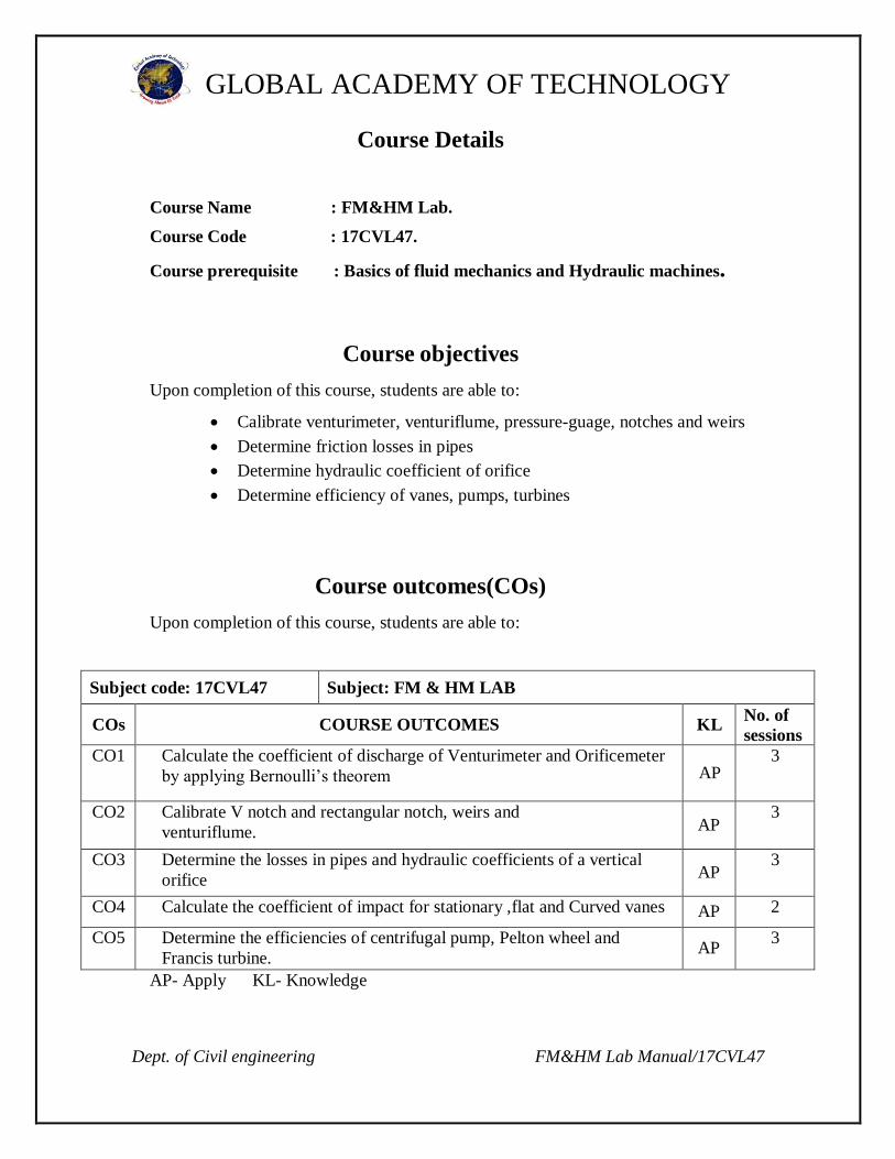
Course Details
Course Name : FM&HM Lab.
Course Code : 17CVL47.
Course prerequisite : Basics of fluid mechanics and Hydraulic machines.
Course objectives
Upon completion of this course, students are able to:
Calibrate venturimeter, venturiflume, pressure-guage, notches and weirs
Determine friction losses in pipes
Determine hydraulic coefficient of orifice
Determine efficiency of vanes, pumps, turbines
Course outcomes(COs)
Upon completion of this course, students are able to:
Subject code: 17CVL47 Subject: FM & HM LAB
COs COURSE OUTCOMES KL No. of
sessions
CO1 Calculate the coefficient of discharge of Venturimeter and Orificemeter
by applying Bernoulli’s theorem AP 3
CO2 Calibrate V notch and rectangular notch, weirs and
venturiflume. AP 3
CO3 Determine the losses in pipes and hydraulic coefficients of a vertical
orifice AP 3
CO4 Calculate the coefficient of impact for stationary ,flat and Curved vanes AP 2
CO5 Determine the efficiencies of centrifugal pump, Pelton wheel and
Francis turbine. AP
3
AP- Apply KL- Knowledge
Dept. of Civil engineering FM&HM Lab Manual/17CVL47
GLOBAL ACADEMY OF TECHNOLOGY
Write up 9
Conduction 42
Viva-Voce 9
Total 60
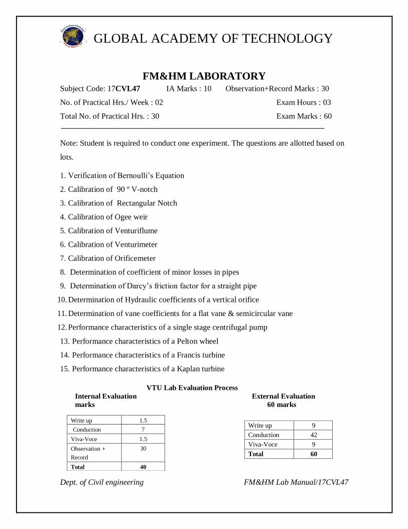
FM&HM LABORATORY Subject Code: 17CVL47 IA Marks : 10 Observation+Record Marks : 30
No. of Practical Hrs./ Week : 02 Exam Hours : 03
Total No. of Practical Hrs. : 30 Exam Marks : 60
Note: Student is required to conduct one experiment. The questions are allotted based on
lots.
1. Verification of Bernoulli’s Equation
2. Calibration of 90 º V-notch
3. Calibration of Rectangular Notch
4. Calibration of Ogee weir
5. Calibration of Venturiflume
6. Calibration of Venturimeter
7. Calibration of Orificemeter
8. Determination of coefficient of minor losses in pipes
9. Determination of Darcy’s friction factor for a straight pipe
10. Determination of Hydraulic coefficients of a vertical orifice
11. Determination of vane coefficients for a flat vane & semicircular vane
12. Performance characteristics of a single stage centrifugal pump
13. Performance characteristics of a Pelton wheel
14. Performance characteristics of a Francis turbine
15. Performance characteristics of a Kaplan turbine
VTU Lab Evaluation Process
Internal Evaluation External Evaluation
marks 60 marks
Write up 1.5
Conduction 7
Viva-Voce 1.5
Observation +
Record
30
Total 40
Dept. of Civil engineering FM&HM Lab Manual/17CVL47
GLOBAL ACADEMY OF TECHNOLOGY
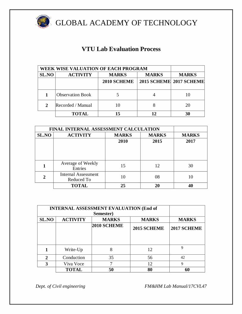
VTU Lab Evaluation Process
WEEK WISE VALUATION OF EACH PROGRAM
SL.NO ACTIVITY MARKS MARKS MARKS
2010 SCHEME
2015 SCHEME
2017 SCHEME
1 Observation Book 5 4 10
2 Recorded / Manual 10 8 20
TOTAL 15 12 30
FINAL INTERNAL ASSESSMENT CALCULATION
SL.NO ACTIVITY MARKS MARKS MARKS
2010
2015
2017
1 Average of Weekly
Entries 15 12 30
2 Internal Assessment
Reduced To 10 08 10
TOTAL 25 20 40
INTERNAL ASSESSMENT EVALUATION (End of Semester)
SL.NO ACTIVITY MARKS MARKS MARKS
2010 SCHEME
2015 SCHEME
2017 SCHEME
1 Write-Up 8 12 9
2 Conduction 35 56 42
3 Viva Voce 7 12 9
TOTAL 50 80 60
Dept. of Civil engineering FM&HM Lab Manual/17CVL47
GLOBAL ACADEMY OF TECHNOLOGY
PREFACE
This manual was designed in accordance to the syllabus
prescribed by V.T.U for the fourth semester FM&HM Lab.
The manual is designed to help students understand both the
theoretical concepts involved in the experiments as well as the
steps needed to carry out the experiments. It gives detailed insight
into the working principles of the various flow devices, pumps and
turbines. This course also includes assignments which give the
complete idea of the concepts used and applied.
Dept. of Civil engineering FM&HM Lab Manual/17CVL47
GLOBAL ACADEMY OF TECHNOLOGY
TABLE OF CONTENTS
1. Verification of Bernoulli’s Equation
2. Calibration of 90 º V-notch
3. Calibration of Rectangular Notch
4. Calibration of Ogee weir
5. Calibration of Venturiflume
6. Calibration of Venturimeter
7. Calibration of Orificemeter
8. Determination of coefficient of minor losses in pipes
9. Determination of Darcy’s friction factor for a straight pipe
10. Determination of Hydraulic coefficients of a vertical orifice
11. Determination of vane coefficients for a flat vane & semicircular vane
12. Performance characteristics of a single stage centrifugal pump
13. Performance characteristics of a Pelton wheel
14. Performance characteristics of a Francis turbine
15. Performance characteristics of a Kaplan turbine
REFERENCE BOOKS
1. Experiments in Fluid Mechanics – Sarbjit Singh- PHI Pvt. Ltd.- NewDelhi- 2009-
12-30
2. Hydraulics and Hydraulic Machines Laboratory Manual – Dr. N. Balasubramanya
Dept. of Civil engineering FM&HM Lab Manual/17CVL47
GLOBAL ACADEMY OF TECHNOLOGY
LAB SAFETY DO’S AND DON’TS.
CONDUCT
a) Do not engage in practical jokes or boisterous (noisy) conduct in the laboratory. b) Do not sit on laboratory benches. c) Never run in the laboratory. d) The use of Cell phones, personal audio or video equipment is prohibited in the laboratory. e) The performance of unauthorized experiments is strictly forbidden.
GENERAL PROCEDURE
1. Never leave experiments while in progress. 2. Do not remove any equipment from the laboratory.
3. Coats, bags, and other personal items must be stored in designated areas, not on the bench tops
or in the aisle ways. 4. Always perform the experiments or work precisely as directed by the teacher. 5. Keep your workstation neat and clean.
APPAREL IN THE LABORATORY
1. Wear a full-length, long-sleeved laboratory coat or chemical-resistant apron.
2. Wear shoes that adequately cover the whole foot; low-heeled shoes with non-slip soles are
preferable.
3. Do not wear sandals, open-toed shoes,open-backed shoes, or high-heeled shoes in the
laboratory. 4. Secure loose clothing (especially loose long sleeves, neck ties, or scarves). 5. Remove jewelry (especially dangling jewelry).
6. Clothing that is provocative or contains obscene messages or messages that are contrary to the
mission of the college will not be permitted.
7. Secure Long hair - Long hair can accidentally fall into flames or chemicals. Many hair sprays,
gels, mousses, etc. are flammable! Think about this! Loose, long hair can also block your vision,
which can lead to accidents. 8. Clothing which has advertising is NOT acceptable. 9. Make-up and jewellery are NOT appropriate.
PRECAUTION IS ALWAYS BETTER THAN CURE!!!!

Dept. of Civil engineering FM&HM Lab Manual/17CVL47
GLOBAL ACADEMY OF TECHNOLOGY
CONTENTS
SL. DATE EXPERIMENT PAGE MARKS SIGNATURE
NO NO OBTAINED
1 Coefficient of discharge of notches
2
Venturimeter and orificemeter
3
Friction in pipes
4
Vertical orifice
5
Impact of jet on vanes
6
Variable speed centrifugal pump test rig
7
Pelton turbine test rig
8
Kaplan turbine test rig
9
Venturiflume
10
Bernoulli’s apparatus

Dept. of Civil engineering FM&HM Lab Manual/17CVL47
GLOBAL ACADEMY OF TECHNOLOGY
11
Minor losses
12
Ogee weir
13 Francis turbine

GLOBAL ACADEMY OF TECHNOLOGY
1
GLOBAL ACADEMY OF TECHNOLOGY
EXPERIMENT NO 1
COEFFICIENT OF DISCHARGE OF NOTCHES
AIM: To Determine the coefficient of discharge of different notches .
APPARATUS:
Different notches, Collecting tank, Constant head tank,
Stop watch, scale.
THEORY:
Notch is a structure which is used to measure the rate of flow in canal, streams
and channels. The flow of water in the canals is obstructed by notch structure. This will
cause rise of water on upstream side of notch and head builds above sill level of notch.
This causes the flow over notch. By principle, the kinematic head is converted into static
head and again it converts into kinetic head.
EXPERIMENTAL SETUP:
The experimental setup consists of supply tank with perforated sheets placed
near inlet valve to reduce the velocity of incoming water and to reduce the velocity of
approach. Thus the perforated sheet can reduce eddies and steady flow can be obtained in
the channel.
The notches are fitted in interchangeable groove at the front end of the channel. A
collecting tank is provided to measure the actual discharge.
PROCEDURE:
1. Fix the notch plate in the groove and measure the sill length of the notch.
2. Open the inlet valve and allow the water into the channel to rise up to sill of the notch
in the channel.
3. Measure the water surface level with the help of hook gauge (initial water level) H1.
4. Allow the water to enter into channel and flows over the sill of the notch at steady
state condition.
5. Measure the water surface level with the help of hook gauge (final water level) H2.
6. The difference between initial water level and final water level gives the head causing
flow over the notch.
7. Collect the known volume of water (V) in collecting tank in specified time (t).
8. Determine the actual discharge Qact.
9. Determine the theoretical discharge Qth.
10. Determine the coefficient of discharge Cd .
11. Repeat the step for various heads of water above the sill level of notch in the channel.
2
GLOBAL ACADEMY OF TECHNOLOGY
OBSERVATIONS AND CALCULATIONS:
Observations:
1. Angle of notch (for V notch) θ = 60
2. Length of notch ( for rectangular notch and weirs ) L =
3. Cross section area of collecting tank A = 0.3X0.3
4. Time taken for collection of water t =
5. Rise of water in the tank R =
Model calculations:
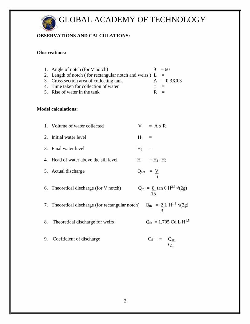
1. Volume of water collected V = A x R
2. Initial water level H1 =
3. Final water level H2 =
4. Head of water above the sill level H = H1- H2
5. Actual discharge Qact = V
t
6. Theoretical discharge (for V notch) Qth = 8 tan θ H2.5 √(2g)
15
7. Theoretical discharge (for rectangular notch) Qth = 2 L H1.5 √(2g)
3
8. Theoretical discharge for weirs Qth = 1.705 Cd L H1.5
9. Coefficient of discharge Cd = Qact
Qth
3
GLOBAL ACADEMY OF TECHNOLOGY
TABULAR COLUMN:
V notch
Rectangular Notch
SL
No
Initial
water
level
H1
Final
water
level
H2
Head
H = H1-
H2
Volume
of water
collected
V
Time taken
for
collection
t
Actual
discharge
Qact
Theoretical
discharge
Qth
Coefficient
of discharge
Cd
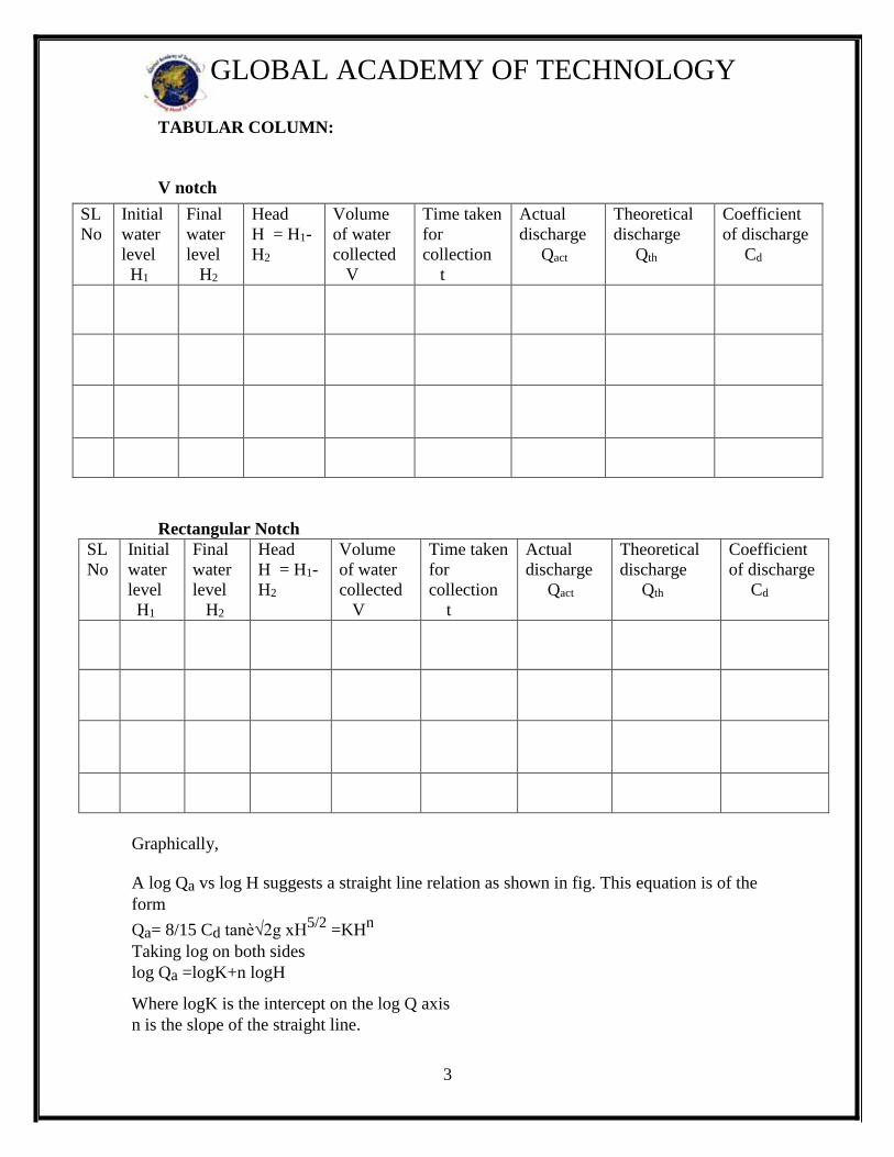
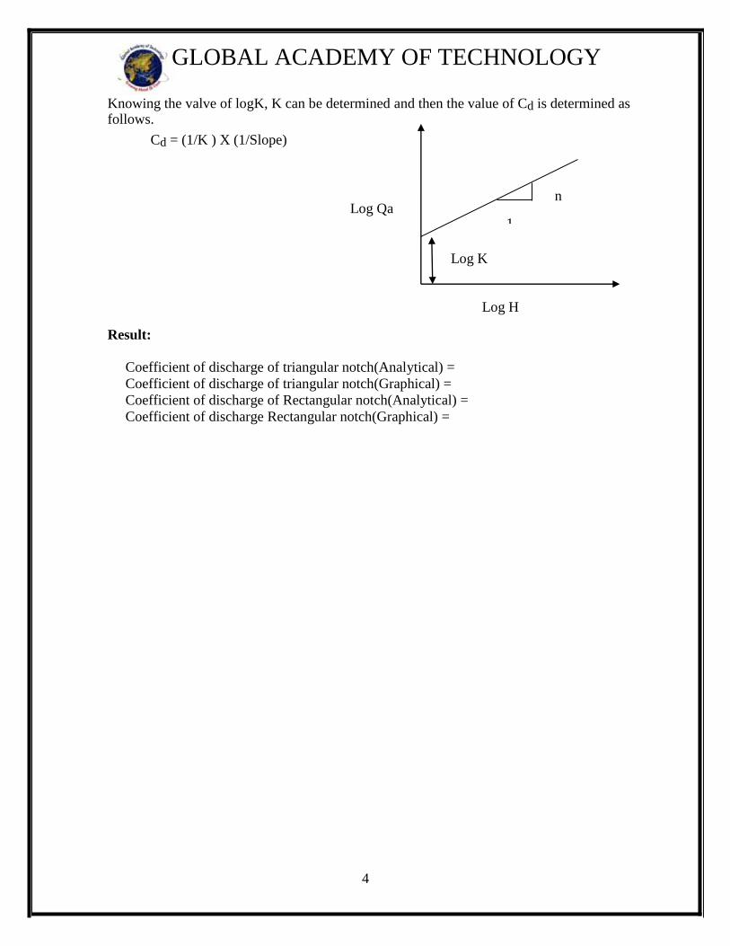
Graphically,
A log Qa vs log H suggests a straight line relation as shown in fig. This equation is of the
form
Qa= 8/15 Cd tanè√2g xH5/2
=KHn
Taking log on both sides
log Qa =logK+n logH
Where logK is the intercept on the log Q axis
n is the slope of the straight line.
SL
No
Initial
water
level
H1
Final
water
level
H2
Head
H = H1-
H2
Volume
of water
collected
V
Time taken
for
collection
t
Actual
discharge
Qact
Theoretical
discharge
Qth
Coefficient
of discharge
Cd
4
GLOBAL ACADEMY OF TECHNOLOGY
Knowing the valve of logK, K can be determined and then the value of Cd is determined as follows.
Cd = (1/K ) X (1/Slope)
Result:
Coefficient of discharge of triangular notch(Analytical) =
Coefficient of discharge of triangular notch(Graphical) =
Coefficient of discharge of Rectangular notch(Analytical) =
Coefficient of discharge Rectangular notch(Graphical) =
Log Qa
Log H
Log K
n
1

5
GLOBAL ACADEMY OF TECHNOLOGY
WORKSHEET
6
GLOBAL ACADEMY OF TECHNOLOGY
EXPERIMENT NO 2
VENTURIMETER AND ORIFICEMETER
AIM: To demonstrate the use of Venturimeter as flow meter and to determine the Co-
efficient of discharge.
APPARATUS:
1. Measuring Tank to measure the flow rate
2. A pipe line with a Venturimeter/orificemeter
3. Tappings with valve are provided at inlet & throat of Venturimeter or the
venacontracta of orificemeter, which are connected to Manometer.
4. A constant steady supply of water with a means of varying the flow rate using
monoblock pump.
THEORY:
A Venturimeter is a device which is used for measuring the rate of flow of fluid
through pipe line. The basic principle on which a venturimeter works is that by reducing
the cross-sectional area of the flow passage, a pressure difference is created between the
inlet and throat and the measurement of the pressure difference enables the determination
of the discharge through the pipe.
A Venturimeter consists of,
1. An inlet section followed by a convergent cone
2. A cylindrical throat &
3. A gradually divergent cone
The inlet section of the Venturimeter is of the same diameter as that of the pipe
which is followed by a convergent cone. The convergent cone is a short pipe which tapers
from the original size of the pipe to that of the throat of the Venturimeter. The throat of
the Venturimeter is a short parallel side tube having its cross-sectional area smaller than
that of the pipe. The divergent cone of the Venturimeter is gradually diverging pipe with
its cross-sectional area increasing from that of the throat to the original size of the pipe.
At the inlet section & the throat of the Venturimeter pressure difference is provided
through manometer.
7
GLOBAL ACADEMY OF TECHNOLOGY
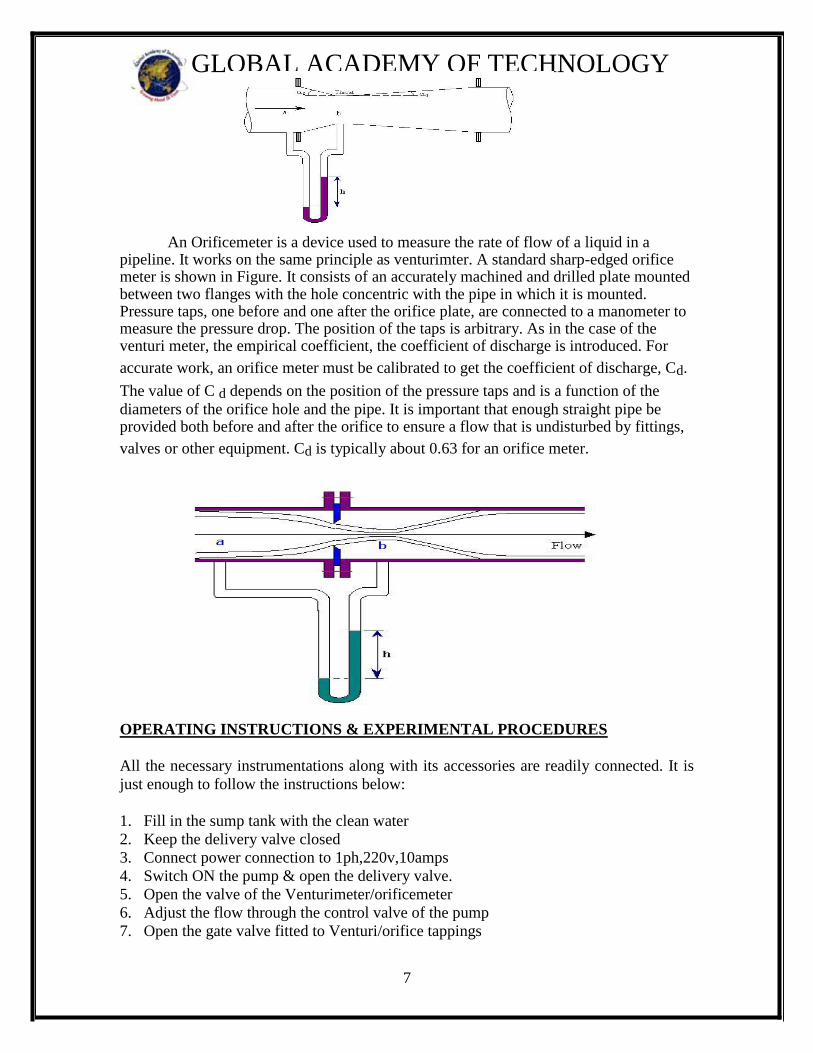
An Orificemeter is a device used to measure the rate of flow of a liquid in a
pipeline. It works on the same principle as venturimter. A standard sharp-edged orifice meter is shown in Figure. It consists of an accurately machined and drilled plate mounted between two flanges with the hole concentric with the pipe in which it is mounted. Pressure taps, one before and one after the orifice plate, are connected to a manometer to measure the pressure drop. The position of the taps is arbitrary. As in the case of the venturi meter, the empirical coefficient, the coefficient of discharge is introduced. For
accurate work, an orifice meter must be calibrated to get the coefficient of discharge, Cd.
The value of C d depends on the position of the pressure taps and is a function of the
diameters of the orifice hole and the pipe. It is important that enough straight pipe be provided both before and after the orifice to ensure a flow that is undisturbed by fittings,
valves or other equipment. Cd is typically about 0.63 for an orifice meter.
OPERATING INSTRUCTIONS & EXPERIMENTAL PROCEDURES
All the necessary instrumentations along with its accessories are readily connected. It is
just enough to follow the instructions below:
1. Fill in the sump tank with the clean water
2. Keep the delivery valve closed
3. Connect power connection to 1ph,220v,10amps
4. Switch ON the pump & open the delivery valve.
5. Open the valve of the Venturimeter/orificemeter
6. Adjust the flow through the control valve of the pump
7. Open the gate valve fitted to Venturi/orifice tappings
8
GLOBAL ACADEMY OF TECHNOLOGY
8. Note down the differential head reading in the Manometer (Expel if any air is there
by opening the drain cocks provided with the Manometer)
9. Operate the PVC Ball Valve to note down the collecting tank reading against the
known time and keep it open when the readings are not taken
10. Change the flow rate & repeat the experiment
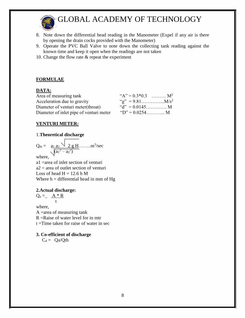
FORMULAE
DATA: Area of measuring tank “A” = 0.3*0.3 ……… M2
Acceleration due to gravity “g” = 9.81…………...M/s2
Diameter of venturi meter(throat) “d” = 0.0145…………. M
Diameter of inlet pipe of venturi meter “D” = 0.0254………... M
VENTURI METER:
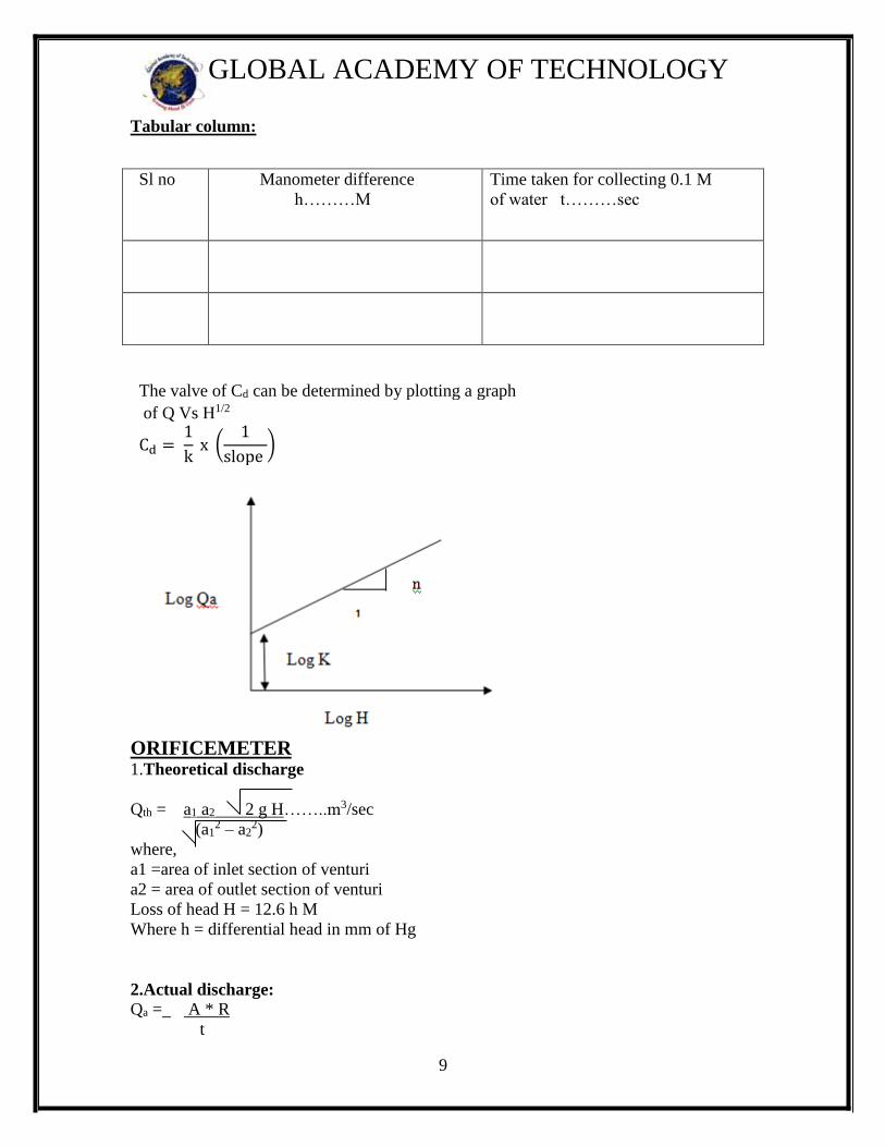
1.Theoretical discharge
Qth = a1 a2 2 g H……..m3/sec
(a12 – a2
2)
where,
a1 =area of inlet section of venturi
a2 = area of outlet section of venturi
Loss of head H = 12.6 h M
Where h = differential head in mm of Hg
2.Actual discharge:
Qa = A * R
t
where,
A =area of measuring tank
R =Raise of water level for in mtr
t =Time taken for raise of water in sec
3. Co-efficient of discharge
Cd = Qa/Qth
9
GLOBAL ACADEMY OF TECHNOLOGY
Tabular column:
The valve of Cd can be determined by plotting a graph
of Q Vs H1/2
Cd = 1
k x (
1
slope )
ORIFICEMETER 1.Theoretical discharge
Qth = a1 a2 2 g H……..m3/sec
(a12 – a2
2)
where,
a1 =area of inlet section of venturi
a2 = area of outlet section of venturi
Loss of head H = 12.6 h M
Where h = differential head in mm of Hg
2.Actual discharge:
Qa = A * R
t
Sl no Manometer difference
h………M
Time taken for collecting 0.1 M
of water t………sec
10
GLOBAL ACADEMY OF TECHNOLOGY
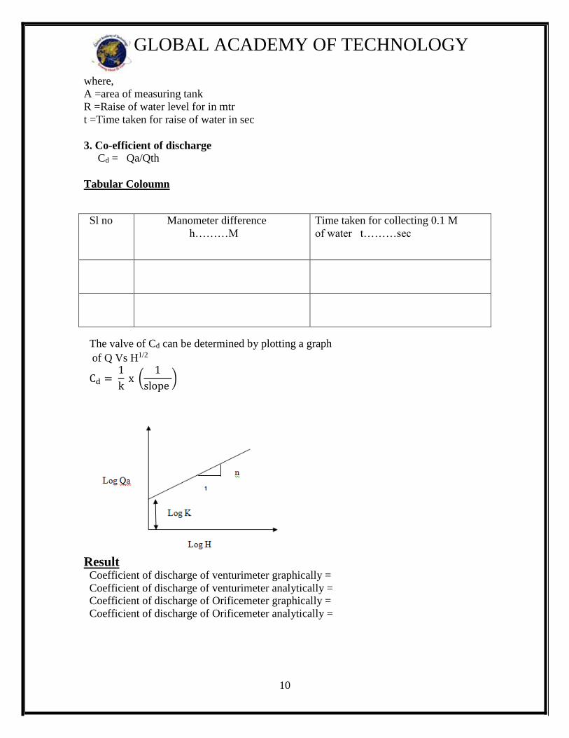
where,
A =area of measuring tank
R =Raise of water level for in mtr
t =Time taken for raise of water in sec
3. Co-efficient of discharge
Cd = Qa/Qth
Tabular Coloumn
The valve of Cd can be determined by plotting a graph
of Q Vs H1/2
Cd = 1
k x (
1
slope )
Result Coefficient of discharge of venturimeter graphically =
Coefficient of discharge of venturimeter analytically = Coefficient of discharge of Orificemeter graphically =
Coefficient of discharge of Orificemeter analytically =
Sl no Manometer difference
h………M
Time taken for collecting 0.1 M
of water t………sec

11
GLOBAL ACADEMY OF TECHNOLOGY
PRECAUTIONS AND THINGS TO REMEMBER:
1. Do not start the pump if the voltage is less than 180V.
2. Do not forget to give electrical neutral & earth connections correctly.
3. Frequently ( once in three months) Grease/oil the rotating parts.
4. Initially, put clean water free from foreign material, and change once in a month.
5. Every week operate the unit for atleast five minutes to prevent clogging of the
moving parts.

12
GLOBAL ACADEMY OF TECHNOLOGY
WORKSHEET

13
GLOBAL ACADEMY OF TECHNOLOGY
14
GLOBAL ACADEMY OF TECHNOLOGY
EXPERIMENT NO 3
FRICTION IN PIPES
(MAJOR LOSSES)
AIM: To determine the coefficient of friction for pipes of different sizes
APPARATUS:
1. Pipe line of ¾,1/2, 1 inched GI pipe.
2. U- Tube manometer with a stabilizing valve to measure the pressure different
across the tapping, one at either end of the pipe line fitted with a Ball Valve
3. A constant steady supply of water with a means of varying the flow rate using
Centrifugal type monoblock pump
4. Measuring tank to measure the flow rate
5. Each pipe line is provided with separate control valve to conduct experiments
separately
THEORY:
A closed circuit of any cross section used for flow of liquid is known as pipe. In
hydraulics, generally pipes are assumed to be running full and of circular cross section.
Liquids flowing through pipes are encountered with resistance resulting in loss of head or
energy of liquids. This resistance is of two types depending upon the velocity of flow.
1. Viscous Resistance and
2. Frictional Resistance due to different diameters
OPERATING INSTRUCTIONS & EXPERIMENTAL PROCEDURES:
All the necessary instrumentations along with its accessories are readily connected. It is
just enough to follow the instructions below:
1. Fill in the Sump Tank with clean water
2. Keep the delivery valve closed
3. Connect the power cable to 1Ph, 220V 10A with earth connection
4. Switch –ON the pump & open the delivery valve
5. Open the corresponding gate valve of the pipe line
6. Adjust the flow through the control valve of the pump
7. Open the corresponding ball valves provided in control panel to measure differential
head
15
GLOBAL ACADEMY OF TECHNOLOGY
8. Note down the differential head reading in the Manometer (Expel if any air is there
by opening the drain cocks provided with the Manometer)
9. Operate the PVC Ball valve to note down the collecting tank reading against the
known time and keep it open when the readings are not taken
10. Change the flow rate & repeat the same procedure.
Tabular column:
Sl no Manometer difference
h………M
Time taken for collecting 0.1 M
of water t………sec
INITIAL DATA:
Area of measuring tank (A) = 0.3X0.3
Length of pipe (l) = 1.85
Density of water (ρ) =1000 kg/m3
Acceleration due to gravity (g) = 9.81m/sec2
Diameter of pipes (d) = 1/2, 3/4, 1 inch pipe
Constants:
Diameter of the pipe (d) =
Length of tapping distance L =
Area of the collecting tank A =
Raise in collecting tank water level R =
Time taken for collection of water, t =
Differential head, in room temperature h =
Density of manometer liquid, Sm =13600 m3/sec
Density of water, Sw =1000 m3/sec
Kinematic viscosity of water v =
Calculations:
Actual discharge Qact = A*R m3/sec
t
Differential pressure head in terms of water head,
hf =h ((Sm/Sw -1) m
16
GLOBAL ACADEMY OF TECHNOLOGY
Area of the pipe a = Π (d 2) m2
4
Velocity of the pipe, V = Qact m/sec
a
Coefficient of Friction, f = h x d x 2g
4 x l x V2
PRECAUTIONS:
1. Do not start the pump if the voltage is less than 230V
2. Do not forget to give electrical neutral & earth connections correctly
3. Frequently (At least once in three months) Grease/oil the rotating parts
4. Initially, put clean water free from foreign material, and change once in three
months.
5. At least every week operate the unit for five minutes to prevent clogging of the
moving parts
Result : Coefficient of friction of Pipe =

17
GLOBAL ACADEMY OF TECHNOLOGY
WORKSHEET
18
GLOBAL ACADEMY OF TECHNOLOGY
EXPERIMENT NO 4
VERTICAL ORIFICE
AIM: To determine the coefficient of velocity (Cv), Coefficient of contraction (Cc),
coefficient of discharge (Cd), for a sharp edged circular orifice.
APPARATUS: 1. Header tank with the sharp edged orifice in the vertical plane of the tank. 2. A steady water supply with means of varying the discharge.
3. A vertical sight glass tube to record the water level in the tank.
4. A travelling distance gauge to facilitate accurate measurement of x and y
5. Slide callipers.
PROCEDURE:
1. Fill soft clean water into the sump tank up to 25 to 30 mm below the full level.
2. Fix any desired orifice in position to the side of the headed tank and secure it.
3. Connect the power chord to the electrical power source, the mains indicator will
glow. 4. Open fully the pump bypass valve and measuring tank, butterfly valve, keeping
all other valves situated under the headed tank closed. 5. Push the starter (green) button and start the pump.
6. Close the pump bypass valve partially to allow water into headed tank. 7. Maintain any derived constant head of water over the orifice or mouthpiece by
selecting any one of the three over flow valves. 8. A jet of water issues out of the fixed orifice or mouthpiece and fall into the
collecting /measuring tank. 9. Regulate the by pass valve so that a small quantity of water flow through the
selected constant head over flow pipe. 10. Note down the following readings and tabulate
a) Head of water indicted on the headed tank piezometer b) Co-ordinates X and Y are measured approximately at vena contracta (in
case of orifice only) and at a short distance along X axis through from vena contracta.
c) Quantity of water collected in the measuring tank up to 10cm height against tank‘t’ on the piezometer tube of the measuring tank.
11. Repeat the experiment by varying the head over the orifice or mouthpiece.
Tabulate the readings and calculate Cv, Cc, Cd for the given orifice or mouthpiece.
19
GLOBAL ACADEMY OF TECHNOLOGY
Calculations:(Any one trial) To find Coefficient of discharge Cd : Actual discharge= Qact= Ar/t
A = Area of measuring tank
r = Rise of water level in the measuring tank
t = time for r cm rise in measuring tank Theoretical discharge Qth = ao √2gH
Where ao= area of the orifice in m2
H= Head over the orifice plate in m.
𝑪𝒅 = 𝑸𝒂𝒄𝒕
𝑸𝒕𝒉
To find Coefficient of velocity Cv : I-method: Actual Velocity = Vact = Qact / ao
Theoretical Velocity = Vth = √2gH
𝐶𝑣 = 𝑉𝑎𝑐𝑡
𝑉𝑡ℎ
II-method:
Cv = X/√4𝐻𝑌 Where X= Horizontal distance of point of deviation from vena contracta Y= vertical distance of point of deviation from vena contracta H = Head over the orifice
To find coefficient of contraction in Cc
Cc = 𝐶𝑑
𝐶𝑣
Tabular column:
Type of orifice-
Dimension of the orifice-
Initial X coordinate = Initial Y coordinate=
20
GLOBAL ACADEMY OF TECHNOLOGY
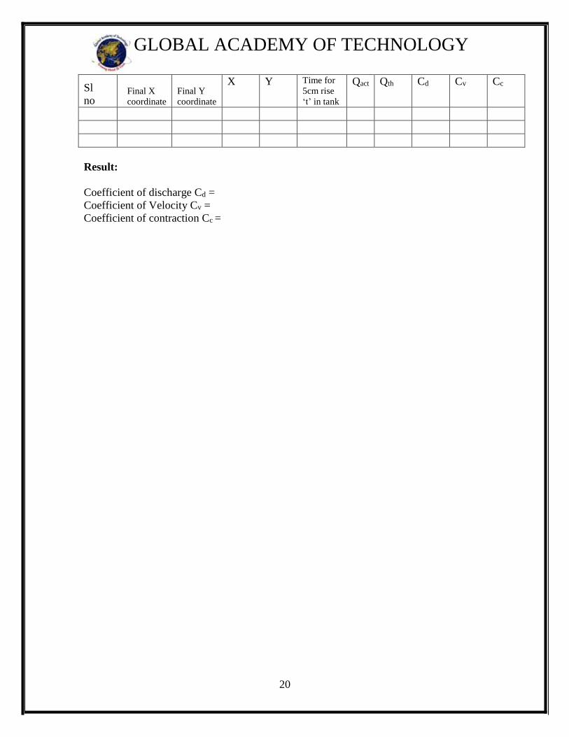
Sl
no Final X
coordinate
Final Y
coordinate
X Y Time for
5cm rise
‘t’ in tank
Qact Qth Cd Cv Cc
Result:
Coefficient of discharge Cd =
Coefficient of Velocity Cv =
Coefficient of contraction Cc =

21
GLOBAL ACADEMY OF TECHNOLOGY
WORKSHEET

22
GLOBAL ACADEMY OF TECHNOLOGY
EXPERIMENT NO 5
IMPACT OF JET ON VANES
AIM: To determine the Co-efficient of impact jet – vanes combination by the force for
stationary vanes of different shapes VIZ: Hemispherical, Flat plate, inclined plate.
THEORY:
When jet of water is directed to hit the vane of particular shape, the force is
exerted on it by fluid in the opposite direction. The amount of force exerted depends on
the diameter of jet, shape of vane, fluid density, and flow rate of water. More importantly,
it also depends on whether the vane is moving or stationary. In our case, we are concern
about the force exerted on stationary vanes. The following are the figures and formulae
for different shapes of vane, based on flow rate.
HEMISPHERICAL Ft = 2 ρ A V2/g
FLAT PLATE Ft = ρ A V2/g
INCLINED PLATE Ft = (ρ A V2/g) sin2θ
Where,
g = 9.81m/sec2
A = Area of jet in m2
ρ = Density of water = 1000 Kg/m3
V = Velocity of jet in m/sec=Q/A
23
GLOBAL ACADEMY OF TECHNOLOGY
θ = Angle of deflected vanes makes with the axis of striking jet, 45 degree.
Ft = theoretical force acting parallel to the direction of jet
Fa = Actual force acting parallel to the direction of jet
DESCRIPTION:
It is a closed circuit water re-circulating system consisting of sump tank,
mono block pump set, and jet / vane chamber. The water is drawn from sump to mono
block pump and delivers it vertically to the nozzle. The flow control valve is also
provided for controlling the water into the nozzle. The water issued out of nozzle as jet.
The jet is made to strike the vane, the force of which is transferred directly to the vane. A
collecting tank with piezo meter to measure discharge. The provision is made to change
the size of nozzle/jet and vane of different shapes.
SPECIFICATIONS:
Vane shapes : Flat, Hemispherical, Inclined (standard) & any other optional
shapes at extra cost.
Jets diameter : 6mm.
Measurements: Pressure of jet by pressure gauges and discharge by collecting
tank with the help of stop watch
Pump : 1 hp, single phase, 230volt with starter
Type : Recirculating with sump & jet chamber made of stainless steel.
Jet chamber : Fixed with toughened glass windows with leak proof rubber
gaskets.
OPERATION:
1. Fix the required diameter jet and the vane of required shape in position.
2. Keep the delivery valve closed & switch ON the pump.
3. Close the front transparent cover tightly.
4. Open the delivery valve and adjust the flow rate of water by gate wall provided.
5. Note down the diameter of jet, shape of vane, flow rate & force and tabulate the
results.
6. This way take readings for 1) different flow rates
2) Different vanes
24
GLOBAL ACADEMY OF TECHNOLOGY
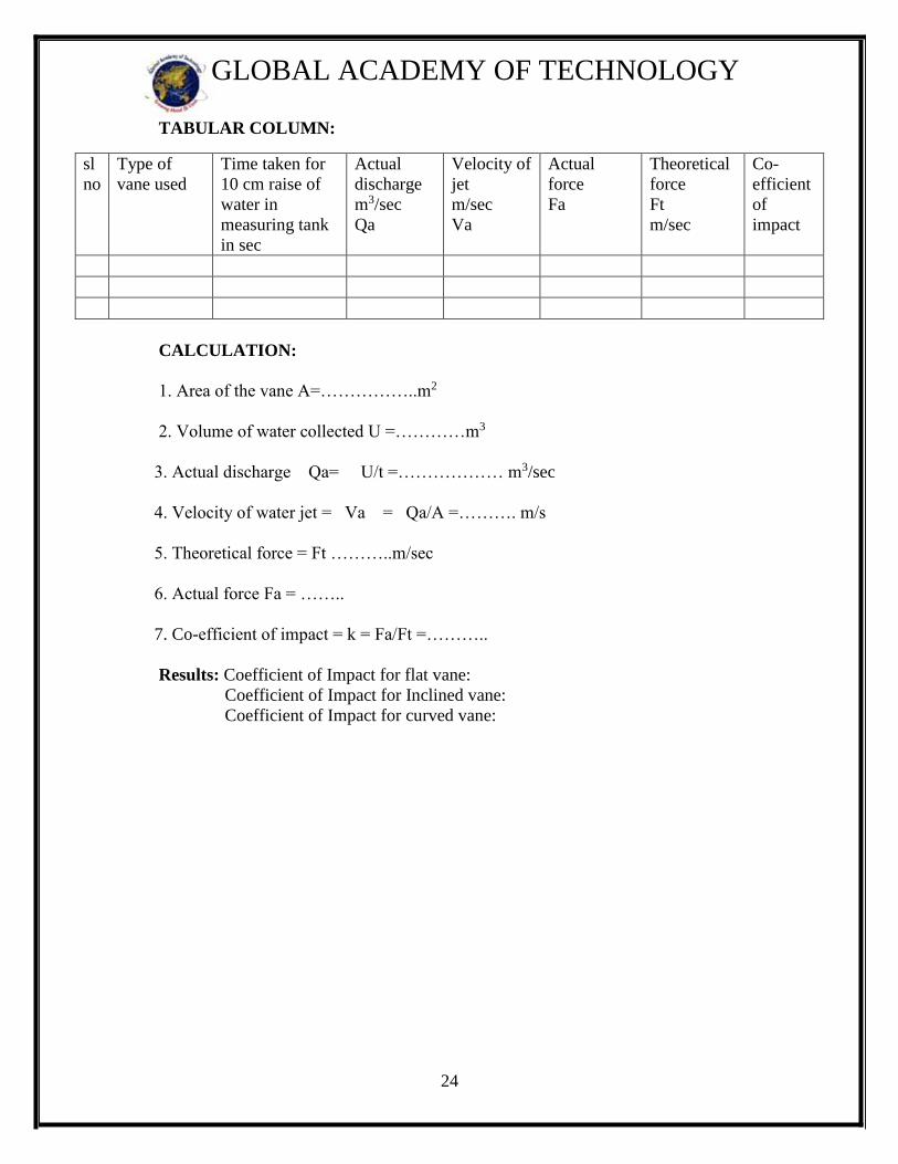
TABULAR COLUMN:
CALCULATION:
1. Area of the vane A=……………..m2
2. Volume of water collected U =…………m3
3. Actual discharge Qa= U/t =……………… m3/sec
4. Velocity of water jet = Va = Qa/A =………. m/s
5. Theoretical force = Ft ………..m/sec
6. Actual force Fa = ……..
7. Co-efficient of impact = k = Fa/Ft =………..
Results: Coefficient of Impact for flat vane:
Coefficient of Impact for Inclined vane:
Coefficient of Impact for curved vane:
sl
no
Type of
vane used
Time taken for
10 cm raise of
water in
measuring tank
in sec
Actual
discharge
m3/sec
Qa
Velocity of
jet
m/sec
Va
Actual
force
Fa
Theoretical
force
Ft
m/sec
Co-
efficient
of
impact

25
GLOBAL ACADEMY OF TECHNOLOGY
WORKSHEET:
26
GLOBAL ACADEMY OF TECHNOLOGY
EXPERIMENT NO 6
VARIABLE SPEED CENTRIFUGAL PUMP TEST RIG
AIM: To determine the efficiency of the centrifugal pump
INTRODUCTION:
In general, a pump may be defined as a mechanical device which, when interposed in a
pipe line, converts the mechanical energy supplied to it from some external source into
hydraulic energy, thus resulting in the flow of liquid from lower potential to higher
potential.
The pumps are of major concern to most Engineers and Technicians. The types of pump
vary in principle and design. The selection of the pump for any particular application is to
be done by understanding their characteristics. The most commonly used pumps for
domestic, agricultural and industrial purposes are: Centrifugal, Piston, Axial Flow (Stage
Pumps), Air jet, Diaphragm and Turbine pumps. Most of these pumps fall into the main
class, namely: Rotodynamic, Reciprocating (Positive Displacement), Fluid (Air) operated
pumps.
While the principle of operation of other pumps is discussed elsewhere, the Centrifugal
pump which is of present concern falls into the category of Rotodynamic pumps. In this
pump, the liquid is made to rotate in a closed chamber (Volute Casing), thus creating the
centrifugal action, which gradually builds the pressure gradient towards outlet thus
resulting in the continuous flow. These pumps compared to Reciprocating Pumps are
simple in construction, more suitable for handling viscous, turbid (Muddy) liquids can be
directly coupled to high-speed electric motors (without any speed reduction), easy to
maintain. But, their hydraulic heads per stage at low flow rates is limited, and hence not
suitable for very high heads compared to Reciprocating Pumps of same capacity. But,
still in most cases, this is the only type of pump, which is being widely used for
agricultural applications because of its practical suitability. The present test rig allows the
students to understand and draw the operating characteristics at various heads and flow
rates and speeds.
DESCRIPTION:
The present pump test rig is a self-contained unit operated on closed circuit (Re
circulation) basis. The Centrifugal pump, DC Motor with suitable DC drive, sump tank,
collecting tank, Control panel are mounted on rigid frame work
with arranged with the following provisions:
1. To measure overall input power to the DC Motor using Energy Meter and stop
watch.
2. For recording the Pressure & Vacuum
3. For changing the Pressure by operating the delivery valve.
4. For measuring the discharge by Collecting Tank
27
GLOBAL ACADEMY OF TECHNOLOGY
OPERATING INSTRUCTIONS:
All the necessary instrumentations along with its accessories are readily connected. It is
just enough to follow the instructions below:
1) Fill in the Sump Tank with clean water
2) Keep the delivery valve closed after initially priming the pump
3) Connect the power cable to single Phase, 230 V, 5A with earth connection
4) Prime the pump using priming valve and close it after priming.
5) Switch –ON the mains and slowly vary the voltage regulator provided in the DC drive
and keep it at required speed.
6) Now, you will find the water starts flowing to the Measuring tank
7) Close the delivery valve slightly, so that the delivery pressure is readable
8) Operate the PVC Ball valve to note down the collecting tank reading against the
known time and keep it open when the readings are not taken
9) Note down the Pressure Gauges, Vacuum Gauges, and time for Energy Meter
reading.
10) Note down the other readings as indicated in the Tabular Column
11) Repeat the experiment for different pressures.
12) Tabulate the readings as shown in tabular column and calculate the results using
Formulae
13) Similarly repeat the experiment for different speeds
14) After the experiment is over, switch off the pump.
28
GLOBAL ACADEMY OF TECHNOLOGY
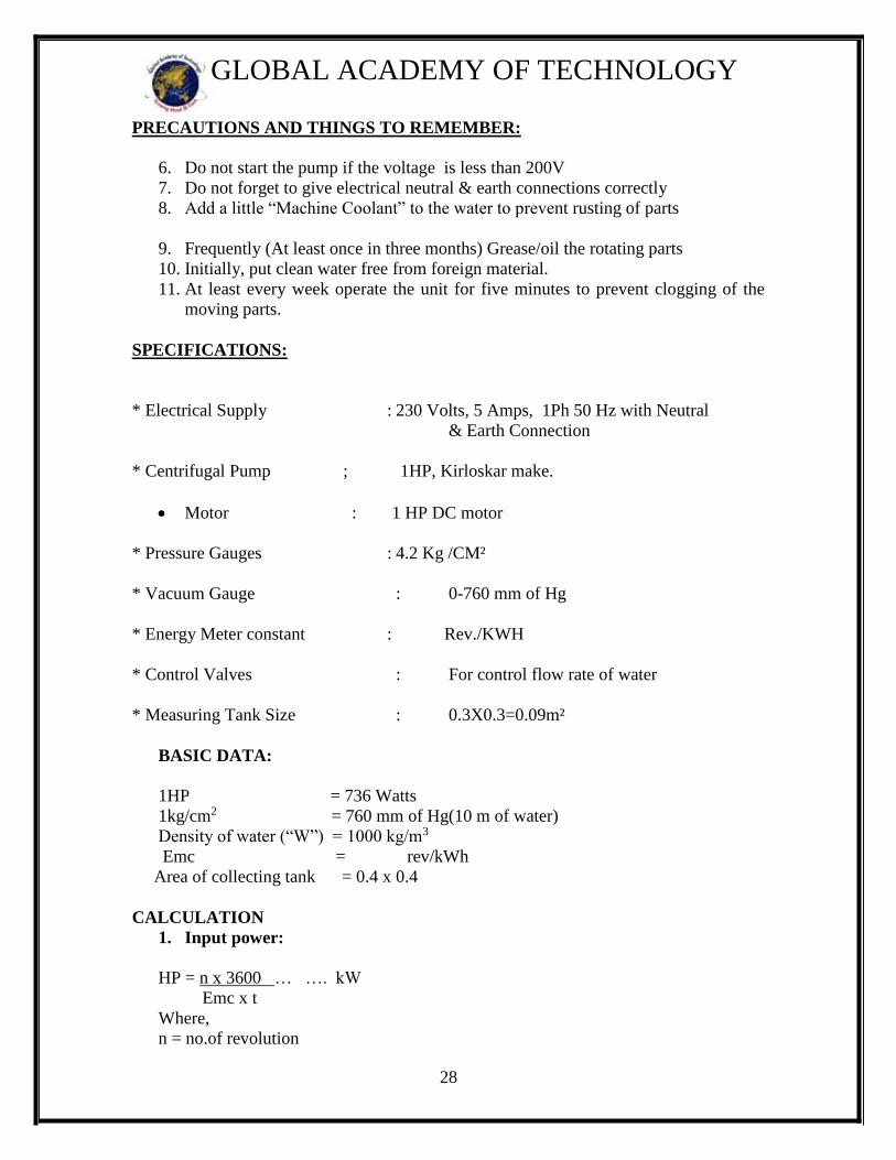
PRECAUTIONS AND THINGS TO REMEMBER:
6. Do not start the pump if the voltage is less than 200V
7. Do not forget to give electrical neutral & earth connections correctly
8. Add a little “Machine Coolant” to the water to prevent rusting of parts
9. Frequently (At least once in three months) Grease/oil the rotating parts
10. Initially, put clean water free from foreign material.
11. At least every week operate the unit for five minutes to prevent clogging of the
moving parts.
SPECIFICATIONS:
* Electrical Supply : 230 Volts, 5 Amps, 1Ph 50 Hz with Neutral
& Earth Connection
* Centrifugal Pump ; 1HP, Kirloskar make.
Motor : 1 HP DC motor
* Pressure Gauges : 4.2 Kg /CM²
* Vacuum Gauge : 0-760 mm of Hg
* Energy Meter constant : Rev./KWH
* Control Valves : For control flow rate of water
* Measuring Tank Size : 0.3X0.3=0.09m²
BASIC DATA:
1HP = 736 Watts
1kg/cm2 = 760 mm of Hg(10 m of water)
Density of water (“W”) = 1000 kg/m3
Emc = rev/kWh
Area of collecting tank = 0.4 x 0.4
CALCULATION
1. Input power:
HP = n x 3600 … …. kW
Emc x t
Where,
n = no.of revolution
29
GLOBAL ACADEMY OF TECHNOLOGY
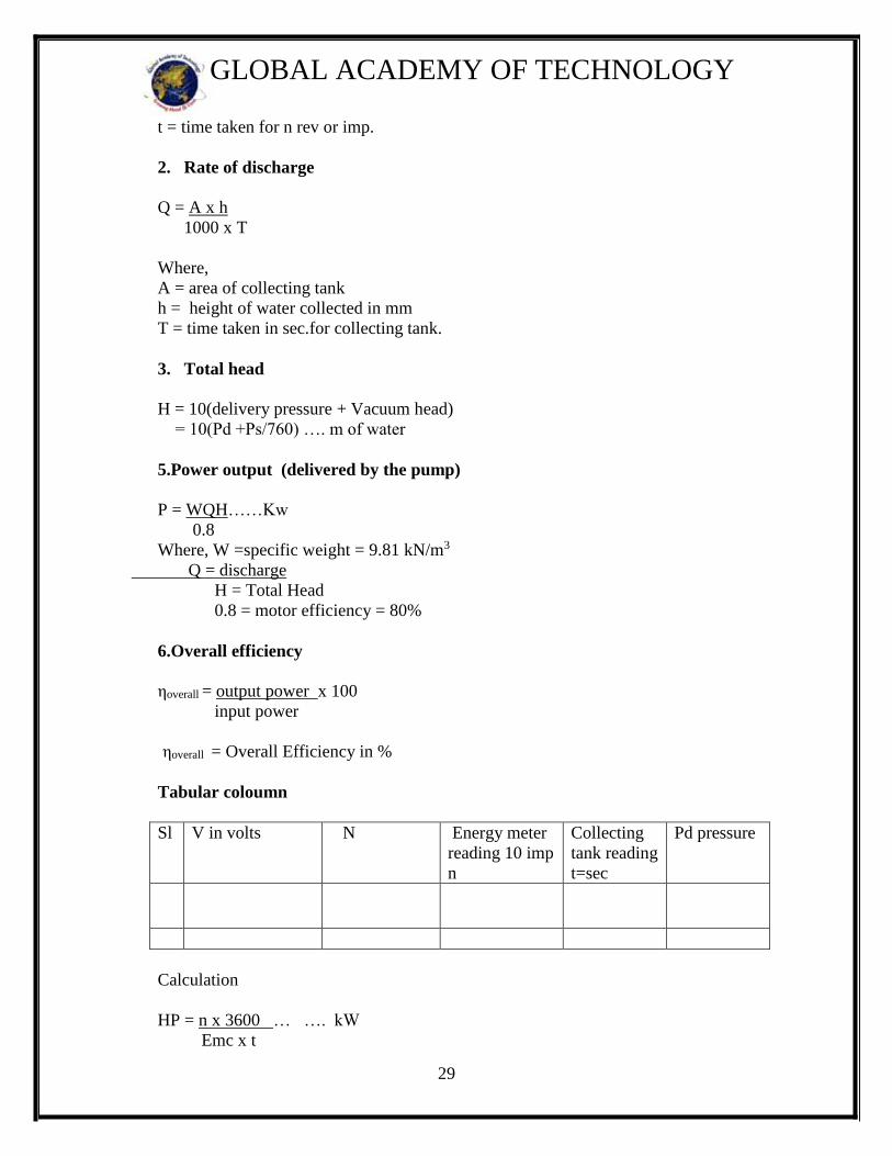
t = time taken for n rev or imp.
2. Rate of discharge
Q = A x h
1000 x T
Where,
A = area of collecting tank
h = height of water collected in mm
T = time taken in sec.for collecting tank.
3. Total head
H = 10(delivery pressure + Vacuum head)
= 10(Pd +Ps/760) …. m of water
5.Power output (delivered by the pump)
P = WQH……Kw
0.8
Where, W =specific weight = 9.81 kN/m3
Q = discharge
H = Total Head
0.8 = motor efficiency = 80%
6.Overall efficiency
ηoverall = output power x 100
input power
ηoverall = Overall Efficiency in %
Tabular coloumn
Sl V in volts N Energy meter
reading 10 imp
n
Collecting
tank reading
t=sec
Pd pressure
Calculation
HP = n x 3600 … …. kW
Emc x t

30
GLOBAL ACADEMY OF TECHNOLOGY
= 10X3600
30.43X1600
Where,
n = no.of revolution
t = time taken for n rev or imp.
Graphs:
Main characteristic curves
i. ηo v/s N
ii. O/P v/s N
iii. Q v/s N
Operating characteristic curves
i. ηo v/s H
ii. O/P v/s H
iii. Q v/s H
Results: Overall Efficieny analytically =
Overall Efficiency graphically =

31
GLOBAL ACADEMY OF TECHNOLOGY
WORKSHEET
32
GLOBAL ACADEMY OF TECHNOLOGY
EXPERIMENT NO 7
PELTON TURBINE TEST RIG
AIM: To determine the efficiency of the pelton wheel turbine
INTRODUCTION
The Pelton Turbine test rig is supplied as a complete set to conduct experiments on model
Pelton turbine in Engineering colleges and Technical institutions. It has been specially
designed to conduct experiments in metric units. The test rig mainly consists of (1) Pelton
turbine (2)Flow measuring unit consisting of a venturimeter and pressure gauges and (3)
Piping system (4)A suitable capacity sump tank (5) suitable capacity Pump.
GENERAL DESCRIPTION
The unit essentially consists of casing with a large circular transparent window kept at the
front for the visual inspection of the impact of the jet on buckets a bearing pedestals rotor
assembly of shaft, runner and brake drum, all mounted on a suitable sturdy iron base
plate. A rope brake arrangement is provided to load the turbine. The input to the turbine
can be controlled by adjusting the spear position by means of a hand wheel fitted with
indicator arrangement. The water inlet pressure, by a pressure gauge and for the
measurement of speed, use a rpm indicator.
CONSTRUCTIONAL SPECIFICATION
1. CASING : Of closed Mild steel having a large circular transparent window.
2. RUNNER: Of cast gun metal is fitted with accurately finished gun metal buckets and
Powder coated.
3. NOZZLE: Of stainless steel designed for smooth flow.
4. SPEAR : Of stainless steel designed for efficient operation.
5. BRAKE ARRANGEMENT: Consisting of a machined and polished Brake drum
cooling water pipes, internal water scoop discharge pipes, Standard cast iron dead weight
spring balance, rope brake etc. arranged for loading the turbine.
TECHNICAL SPECIFICATION
PELTON TURBINE(IMPULSE TURBINE)
1. Rated Supply Head :
2. Discharge :
33
GLOBAL ACADEMY OF TECHNOLOGY
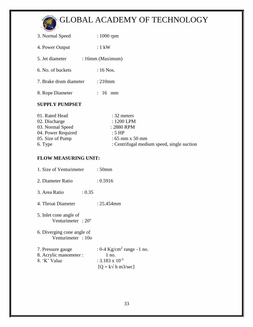
3. Normal Speed : 1000 rpm
4. Power Output : 1 kW
5. Jet diameter : 16mm (Maximum)
6. No. of buckets : 16 Nos.
7. Brake drum diameter : 210mm
8. Rope Diameter : 16 mm
SUPPLY PUMPSET
01. Rated Head : 32 meters
02. Discharge : 1200 LPM
03. Normal Speed : 2880 RPM
04. Power Required : 5 HP
05. Size of Pump : 65 mm x 50 mm
6. Type : Centrifugal medium speed, single suction
FLOW MEASURING UNIT:
1. Size of Venturimeter : 50mm
2. Diameter Ratio : 0.5916
3. Area Ratio : 0.35
4. Throat Diameter : 25.454mm
5. Inlet cone angle of
Venturimeter : 20o
6. Diverging cone angle of
Venturimeter : 10o
7. Pressure gauge : 0-4 Kg/cm2 range –1 no.
8. Acrylic manometer : 1 no.
8. ‘K’ Value : 3.183 x 10⁻³
[Q = k h m3/sec]
34
GLOBAL ACADEMY OF TECHNOLOGY
INSTALLATION
The turbine is placed on the sump tank level. The supply pumpset draws water from the
main underground. The gate valve is provided just above the inlet bend of the turbine to
regulate the discharge and net supply head on the turbine in relation to the spear settings.
A spear and nozzle arrangement is provided on one side of the runner to control the load
the spear being operates through a hand wheel with suitable indicating gear.
STARTING UP(COMMISSIONING)
Make sure before starting that the pipe lines are free foreign matter. Also note whether all
the joints are water tight and a leak proof. Start pump with closed gate valve. The spear in
the turbine inlet and should also be in the closed position while starting the pump. See
that all the ball bearings and such bearings in the units are properly lubricated. Then
slowly open the gate valve situated above the turbine and read the pressure gauge and see
that the pump develops the rated head. The pump develops the required head, slowly
open the turbine spear by rotating the hand wheel until the turbine attains the normal
speed run the turbine at the normal speed for about 15 min and carefully note the
following.
1. Operation of the bearings, temperature rise, etc.
2. Steady constant speed & speed fluctuations if any.
3.Vibration of the unit.
In addition to this, on the pump side note the operation of the stuffing box. (The stuffing
box should have a drip of water. If the gland is over tightened, the leakage stops but the
packing will heat up burn and damage the shaft).
If the operation of the above parts are normal, load the turbine slowly and take readings.
To load the turbine standard dead weight are provided with figures stamped on them to
indicator their weights. Open the water inlet valve and allow some cooling water through
the brake drum when the turbine runs under load, so that the heat generated by the brake
drum is carried away by the cooling water.
Do not suddenly load the turbine, load the turbine gradually and the same time open the
spear to run the turbine at normal speed.
TO SHUT DOWN
Before switching off the supply pumpset, first remove all the dead weights on the hanger.
Close the cooling inlet water gate valve slowly close the spear to its full closed position.
Then close the gate valve just above turbine. Then switch off the supply pumpset.
Never switch off the supply pumpset when the turbine is working under load.
If the electric lines trips of when the turbine is working first unload the turbine, close all
35
GLOBAL ACADEMY OF TECHNOLOGY
the valve. Start the electric motor again, when the line gets the power and then operate
the turbine by operating the valve in the order said above.
TESTING
Water turbines are tested in the hydraulic laboratory to demonstrate how tests on small
water turbine are carried out, to study their construction, and to given the students a clear
knowledge about the different type of turbines and their characteristics.
Turbine shall be first tested at constant net supply head (at the rated value of 35-40m) by
varying the load, speed and setting. However the net supply head on the turbine may be
reduced and the turbine tested in which case the power developed by the turbine and the
best efficiency speed will also be reduced.
Though the turbine can also be tested at higher net supply heads, the supply pumpset
cannot develop the higher head at the same time maintaining higher of flow.
The output power from the turbine is calculated from the readings taken on the brake and
the speed of the shaft. The input power supplied to the turbine is calculated from the net
supply head on the turbine and discharge through the turbine. Efficiency of the turbine
being the ratio between the output and input can be determined from these two readings.
The discharge is measured by the 50mm venturimeter and with the pressure gauges.
Supply head is measured with help of the pressure gauge.
It is suggested that the turbine shall be tested at normal speed, three speeds below normal
speed. 3 speeds above normal speed covering a range of 50% of the normal speed. The
run away speed(the speed of the turbine at no load and at rated condition of supply head)
and pull out torque(the maximum torque at stalled speed) may also be observed.
After starting and running the turbine at normal speed for some time, load the turbine and
take readings. Note the following:
1. Net supply head
2. Discharge (Pressure gauge readings)
3. Turbine shaft speed
4. Brake weight (Dead Weights plus hanger and rope weight) (1kg)
5. Spring balance reading.
For any particular setting of the spear first run the turbine at light load and then gradually
load it, by adding dead weights on the hanger. The net supply head on the turbine shall be
maintained constant at the rated value, and this can be done by adjusting the gate valve
fitted just above the turbine.
36
GLOBAL ACADEMY OF TECHNOLOGY
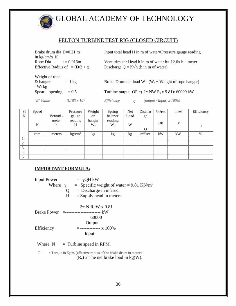
PELTON TURBINE TEST RIG (CLOSED CIRCUIT)
Brake drum dia D=0.21 m Input total head H in m of water=Pressure gauge reading
in kg/cm2x 10
Rope Dia t = 0.016m Venturimeter Head h in m of water h= 12.6x h meter
Effective Radius of = (D/2 + t) Discharge Q = Kh (h in m of water)
Weight of rope
& hanger = 1 kg Brake Drum net load W= (W1 + Weight of rope hanger)
–W2 kg
Spear opening = 0.5 Turbine output OP =( 2 NW Re x 9.81)/ 60000 kW
‘K’ Value = 3.183 x 10⁻³ Efficiency = (output / Input) x 100%
Sl
N
Speed
N
Venturi -
meter
h
Pressure
gauge
reading
H
Weight
on
hanger
W1
Spring
balance
reading
W2
Net
Load
W
Dischar
ge
Q
Output
OP
Input
IP
Efficiency
rpm meters kg/cm2 kg kg kg m3/sec kW kW %
1.
2.
3.
4.
5.
IMPORTANT FORMULA:
Input Power = QH kW
Where = Specific weight of water = 9.81 KN/m3
Q = Discharge in m3/sec.
H = Supply head in meters.
2 N ReW x 9.81
Brake Power =----------------------- kW
60000
Output
Efficiency = ------------- x 100%
Input
Where N = Turbine speed in RPM.
T = Torque in Kg m, (effective radius of the brake drum in meters
(Re) x The net brake load in kg(W).
37
GLOBAL ACADEMY OF TECHNOLOGY
9.MAINTENANCE
As these units are built very sturdily, they do not require any routine or regular
maintenance. However, we recommend the following to be done about once in a year to
increase the life of the elements.
Lubricate all the working parts where provision for lubricating is made. Grease cups are
provided for lubrication ball bearings. Remove the grease drain plugs where fitted, and
inject fresh grease through grease cups until waste grease along with a portion of fresh
grease us ejected out through the grease drain hole. Then run the machine for a few
minutes to eject the excess grease in the bearing housing. Then fit the grease drain plug.
Over greasing results in excessive heat due to a pumping action of the bearing, and it is a
harmful as under greasing.
Clean the stuffing box, repack and lubricating it. If any packing ring it’s worn out,
replace it with good quality as bets graphically packing. While repacking the successive
ring joints should be staggered by 90 or 180 degrees. Tighten the gland nuts evenly and
allow the stuffing box to drip water occasionally to lubricate the packing rings.
Never run the pump without water in it as this would cause damage to stuffing box, bush
bearings etc.
Graph : Plot the graph of Output Versus Input
Results :
Efficiency of Pelton wheel Turbine graphically=
Efficiency Analytically =

38
GLOBAL ACADEMY OF TECHNOLOGY
WORKSHEET

39
GLOBAL ACADEMY OF TECHNOLOGY
EXPERIMENT NO 8
KAPLAN TURBINE TEST RIG
AIM : To conduct Performance test and to determine the efficiency of a kaplan Turbine
APPARATUS: Kaplan Turbine, Digital speed indicator, Pressure gauge, Vacuum gauge,
weights, brake dynamometer, Venturimeter and centrifugal pump.
THEORY: The Kaplan Turbine operates under low heads and large quantities of flow.
The water from the pump enters through the spiral casing into the guide vanes and then to
the runner. While passing through the spiral casing and guide vanes a portion of the
pressure head is converted into kinetic energy. The water enters the runner at a higher
velocity than in the pipe line.
Experimentally, the efficiency is determined in the same way as for Pelton or Francis
Turbines.
EXPERIMENTAL SETUP:- A Kaplan Turbine is an axial flow reaction turbine. It consists essentially of a runner , a
ring of adjustable guide vanes and volute casing. The guide vanes are of aerofoil section
and can be rotated about their axis by means of a hand wheel The runner has four blades
of aerofoil section which is fixed.. The turbine is loaded by putting weights on the hanger
of the brake dynamometer.
Water under pressure is supplied to the turbine by a centrifugal pump. The discharge
from the pump is controlled by means of a butterfly valve fitted in the pipe line. The
discharge in the pipe line and hence through the turbine can be measured with the help of
a venturimeter. The head of water is measured with the help of a pressure gauge and
vacuum gauge.
CONSTRUCTION SPECIFICATION:
A. Spiral Casing : is of close grained cast iron.
B. Runner: is of gunmetal and nickel plated, designed for efficient operation
accurately machined and smoothly finished.
C. Guide Vane Mechanism: Consists of gun metal guide vanes, operated by a hand
wheel through a link mechanism.
D. Shaft: is of EN8 steel accurately machined and provided with a brass and gunmetal
Sleeve at the stuffing box.
E. Ball Bearings: is of double row deep groove rigid type in the casing
And double row self aligning type in the bearing pedestal both of
Liberal size.
F. Draught Bend: is provided at the exit of the runner. To the bend is

40
GLOBAL ACADEMY OF TECHNOLOGY
connected, a straight conical draught tube of steel fabrication.
G. Brake Arrangement: Consisting of a machined and polished cast iron
brake drum, cooling water pipes,
Standard cast iron dead weights, spring balance, rope brake etc.
arranged for loading the turbine.
I. Sump Tank: approximately about 1200 ltr stainless steel tank is provided for
closed circuit operation.
TECHNICAL SPECIFICATION:
01. Rated Supply Head : 10-15 meters approximately
02. Rated Speed : 1000 rpm
03. Power Output : 1kW
04. Runaway Speed : 1750 RPM
05. Runner Diameter : 160 mm
06. No. of guide vanes : 10
07. P.C.D. guide vanes : 230mm
08. Brake Drum Diameter : 360 mm
09. Rope Diameter : 16 mm
SUPPLY PUMP SET
01. Rated Head : 10- 15 meters
02. Discharge : LPM approximately
03. Normal Speed : 2880 RPM
04. Power Required :7.5 HP
05. Size of Pump : 100 mm x 100 mm
06. Type : Centrifugal medium speed, single suction
volute
FLOW MEASURING UNIT :
01. Inlet diameter of venturimeter : 100 mm
02. venturimeter throat Diameter : 48 mm
03. Pressure Gauges : 0-4 Kg/cm2
PROCEDURE:-
1. Connect the power supply to the pump
2. Close the turbine inlet gate valve fully before starting the pump
3. Start the centrifugal pump.
41
GLOBAL ACADEMY OF TECHNOLOGY
4. Allow the water to flow into the turbine by opening the gate valve.
5. Keep the guide vane at desired value where we get max rpm or head
6. Then close the gate valve so as to attain 1000 or 1200 rpm
7. Allow it to sabilibe at that speed
8. Load the turbine gradually say ¼, ½, 3/ 4 & full load by maintaining the turbine
speed 1000RPM by operating the gate valve.
9. Note down the all the parameters as per the tabulation column given below
10. Repeat the experiment for different loads.
11. After the experiment remove the load on the weight hanger and close the gate
valve
10. Stop the pump motor.
12. Calculate the power input, power output and efficiency.
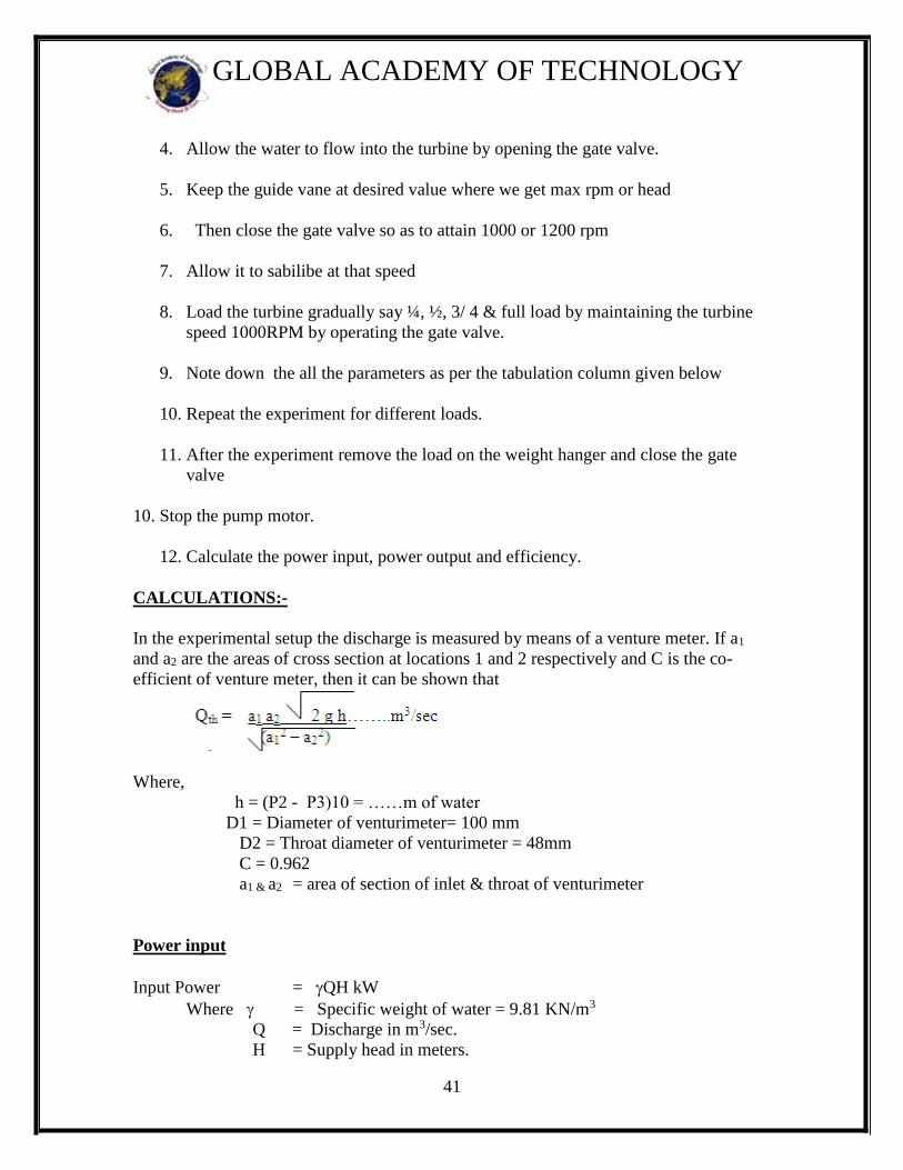
CALCULATIONS:-
In the experimental setup the discharge is measured by means of a venture meter. If a1
and a2 are the areas of cross section at locations 1 and 2 respectively and C is the co-
efficient of venture meter, then it can be shown that
Where,
h = (P2 - P3)10 = ……m of water
D1 = Diameter of venturimeter= 100 mm
D2 = Throat diameter of venturimeter = 48mm
C = 0.962
a1 & a2 = area of section of inlet & throat of venturimeter
Power input
Input Power = QH kW
Where = Specific weight of water = 9.81 KN/m3
Q = Discharge in m3/sec.
H = Supply head in meters.
42
GLOBAL ACADEMY OF TECHNOLOGY
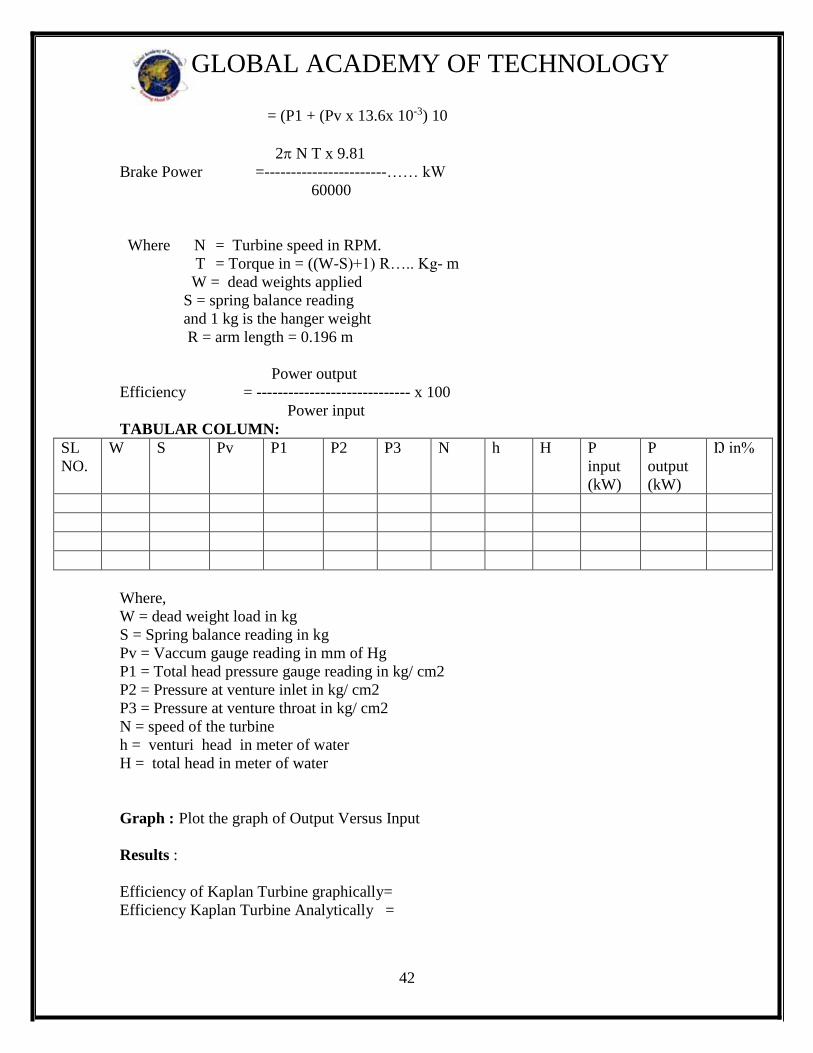
= (P1 + (Pv x 13.6x 10⁻³) 10
2 N T x 9.81
Brake Power =-----------------------…… kW
60000
Where N = Turbine speed in RPM.
T = Torque in = ((W-S)+1) R….. Kg- m
W = dead weights applied
S = spring balance reading
and 1 kg is the hanger weight
R = arm length = 0.196 m
Power output
Efficiency = ----------------------------- x 100
Power input
TABULAR COLUMN:
SL
NO.
W
S
Pv P1 P2 P3 N h H P
input
(kW)
P
output
(kW)
Ŋ in%
Where,
W = dead weight load in kg
S = Spring balance reading in kg
Pv = Vaccum gauge reading in mm of Hg
P1 = Total head pressure gauge reading in kg/ cm2
P2 = Pressure at venture inlet in kg/ cm2
P3 = Pressure at venture throat in kg/ cm2
N = speed of the turbine
h = venturi head in meter of water
H = total head in meter of water
Graph : Plot the graph of Output Versus Input
Results :
Efficiency of Kaplan Turbine graphically=
Efficiency Kaplan Turbine Analytically =

43
GLOBAL ACADEMY OF TECHNOLOGY
WORKSHEET
44
GLOBAL ACADEMY OF TECHNOLOGY
EXPERIMENT NO 9
VENTURIFLUME
AIM: To determine the coefficient of discharge of venturiflume
APPARATUS: 1. Venturiflume with point gauges at the entrance and the throat installed in
an open channel 2. A constant steady supply of water with a means of varying discharge.
3. Measuring tank and stop watch to measure the actual discharge.
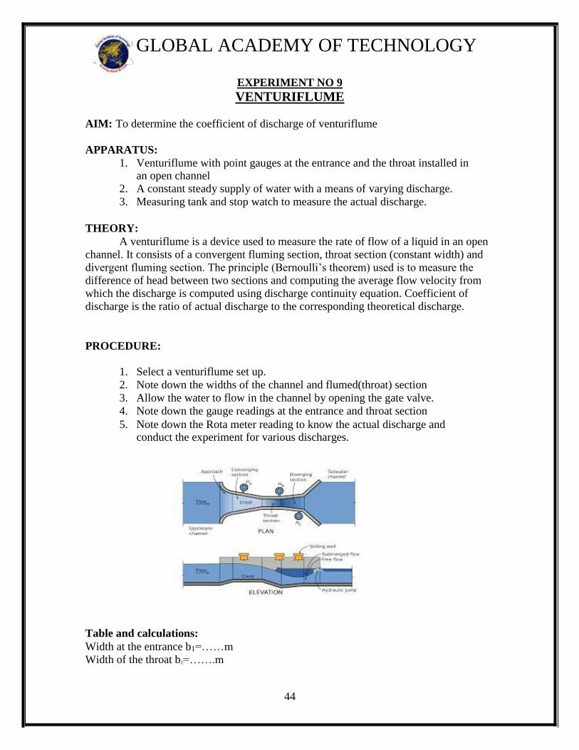
THEORY: A venturiflume is a device used to measure the rate of flow of a liquid in an open
channel. It consists of a convergent fluming section, throat section (constant width) and
divergent fluming section. The principle (Bernoulli’s theorem) used is to measure the
difference of head between two sections and computing the average flow velocity from
which the discharge is computed using discharge continuity equation. Coefficient of
discharge is the ratio of actual discharge to the corresponding theoretical discharge.
PROCEDURE:
1. Select a venturiflume set up.
2. Note down the widths of the channel and flumed(throat) section
3. Allow the water to flow in the channel by opening the gate valve.
4. Note down the gauge readings at the entrance and throat section 5. Note down the Rota meter reading to know the actual discharge and
conduct the experiment for various discharges.
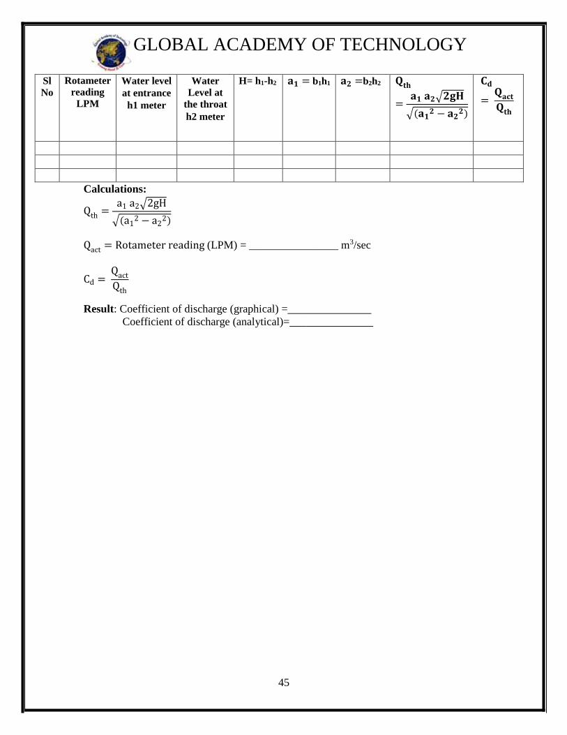
Table and calculations:
Width at the entrance b1=……m
Width of the throat b2=…….m
45
GLOBAL ACADEMY OF TECHNOLOGY
Sl
No
Rotameter
reading
LPM
Water level
at entrance
h1 meter
Water
Level at
the throat h2 meter
H= h1-h2
𝐚𝟏 = b1h1 𝐚𝟐 =b2h2 𝐐𝐭𝐡
=𝐚𝟏 𝐚𝟐√𝟐𝐠𝐇
√(𝐚𝟏𝟐 − 𝐚𝟐
𝟐)
𝐂𝐝
= 𝐐𝐚𝐜𝐭
𝐐𝐭𝐡
Calculations:
Qth =a1 a2√2gH
√(a12 − a2
2)
Qact = Rotameter reading (LPM) = ________________ m3/sec
Cd = Qact
Qth
Result: Coefficient of discharge (graphical) =_______________
Coefficient of discharge (analytical)=_______________

46
GLOBAL ACADEMY OF TECHNOLOGY
WORKSHEET

47
GLOBAL ACADEMY OF TECHNOLOGY
EXPERIMENT NO 10
BERNOULLI’S APPARATUS
AIM: To verify Bernoulli’s theorem
Bernoulli’s Theorem:
In an ideal , incompressible , steady and continuous flow , the sum of pressure energy ,
potential energy , kinetic energy per unit weight of fluid is constant.
The energy per unit weight of fluid (N.m/N) has got a dimension of length (L) and can be
expressed in metres of fluid column , commonly called as head .Thus according to the
BERNOULLI’S theorem , the sum of pressure head ( P/ γ ) ,datum head ( Z ) and the
velocity head ( V2/ 2g )is constant .
i.e. P/ γ + Z + V2/ 2g = constant.
In cases of real fluids , because some energy is always lost in overcoming frictional
resistance , the BERNOULLI’S theorem for real fluids is
P1/ γ + V12/ 2g + Z1 = P2/ γ + V2
2/ 2g + Z 2 +HL2
Where HL is loss of head from section 1 to 2
Experimental Set-up
The set-up consists of a horizontal converging-diverging duct having a varying
width and varying depth. The duct is made of transparent Perspex sheets. A number of
piezometer are fitted on the duct to indicate the piezometric levels at various sections.
The duct is connected to a constant-head tank at one end. The supply tank is fitted
with a piezometer to indicate the water depth. The overflow pipe discharges the excess
water and thus keeps the water level constant.
The water is collected in the measuring tank for determination of the discharge.
A small tank with a valve is provided at the downstream end of the duct.
A graph paper can be fixed on a wooden board placed behind the piezometric tubes
for making the water levels.
PROCEDURE:
1. Allow water to flow from the supply tank by slowly opening the inlet valve .
2. Adjust the flow in such a manner that a constant head of water is available in the
supply tank (i.e inflow = outflow)
3. Note down the quantity of water collected (Q) in the measuring tank for a given
interval of time using a stopwatch.
4. Compute the areas of cross section (A1 and A2) under the piezometer tubes.
48
GLOBAL ACADEMY OF TECHNOLOGY
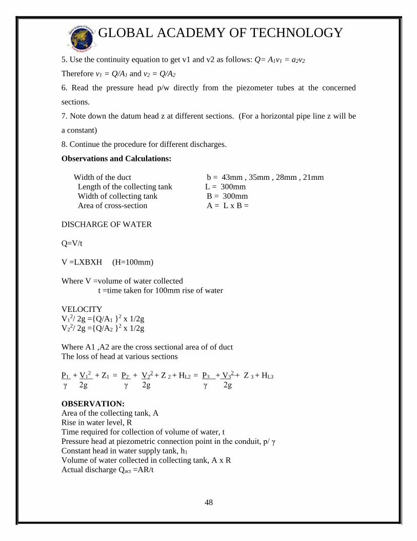
5. Use the continuity equation to get v1 and v2 as follows: Q= A1v1 = a2v2
Therefore v1 = Q/A1 and v2 = Q/A2
6. Read the pressure head p/w directly from the piezometer tubes at the concerned
sections.
7. Note down the datum head z at different sections. (For a horizontal pipe line z will be
a constant)
8. Continue the procedure for different discharges.
Observations and Calculations:
Width of the duct b = 43mm , 35mm , 28mm , 21mm
Length of the collecting tank L = 300mm
Width of collecting tank B = 300mm
Area of cross-section A = L x B =
DISCHARGE OF WATER
Q=V/t
V =LXBXH (H=100mm)
Where V =volume of water collected
t =time taken for 100mm rise of water
VELOCITY
V12/ 2g ={Q/A1 }
2 x 1/2g
V22/ 2g ={Q/A2 }
2 x 1/2g
Where A1 ,A2 are the cross sectional area of of duct
The loss of head at various sections
P1 + V12 + Z1 = P2 + V2
2 + Z 2 + HL2 = P3 + V32 + Z 3 + HL3
γ 2g γ 2g γ 2g
OBSERVATION:
Area of the collecting tank, A
Rise in water level, R
Time required for collection of volume of water, t
Pressure head at piezometric connection point in the conduit, p/ γ
Constant head in water supply tank, h1
Volume of water collected in collecting tank, A x R
Actual discharge Qact =AR/t
49
GLOBAL ACADEMY OF TECHNOLOGY
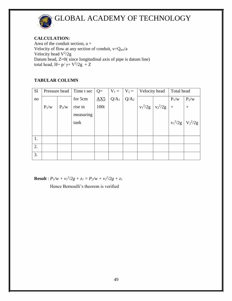
CALCULATION:
Area of the conduit section, a =
Velocity of flow at any section of conduit, v=Qact/a
Velocity head V2/2g
Datum head, Z=0( since longitudinal axis of pipe is datum line)
total head, H= p/ γ+ V2/2g + Z
TABULAR COLUMN
Sl
no
Pressure head Time t sec
for 5cm
rise in
measuring
tank
Q=
AX5
100t
V1 =
Q/A1
V2 =
Q/A2
Velocity head Total head
P1/w
P2/w
v12/2g
v22/2g
P1/w
+
v12/2g
P2/w
+
V22/2g
1.
2.
3.
Result : P1/w + v12/2g + z1 = P2/w + v2
2/2g + z1
Hence Bernoulli’s theorem is verified

50
GLOBAL ACADEMY OF TECHNOLOGY
WORKSHEET
51
GLOBAL ACADEMY OF TECHNOLOGY
EXPERIMENT NO 11
MINOR LOSSES
AIM: To determine the minor losses due to sudden enlargement, sudden contraction and
bend
APPARATUS: A flow circuit of G. I. pipes of different pipe fittings viz. Large bend, Small bend,
Elbow, Sudden enlargement, Sudden contraction, U-tube differential manometer,
collecting tank.
THEORY: When a fluid flows through a pipe, certain resistance is offered to the flowing fluid,
which results in causing a loss of energy. The various energy losses in pipes may be
classified as:
(i) Major losses.
(ii) Minor losses.
The major loss of energy as a fluid flows through a pipe, is caused by friction. It
may be computed mainly by Darcy-Weisbach equation. The loss of energy due to
friction is classified as a major loss because in case of long pipelines. It is usually much
more than the loss of energy incurred by other causes.
The minor losses of energy are those, which are caused on account of the change
in the velocity of flowing fluid (either in magnitude or direction). In case of long pipes
these losses are usually quite small as compared with the loss of energy due to friction
and hence these are termed ‘minor losses’ which my even be neglected without serious
error. However, in short pipes these losses may sometimes outweigh the friction loss.
Some of the losses of energy that may be caused due to the change of velocity are
indicated below
Sudden Enlargement:- Two pipe of cross-sectional area A1 and A2 flanged together
with a constant velocity fluid flowing from smaller diameter pipe. This flow breaks
away from edges of narrow edges section, eddies from and resulting turbulence cause
dissipation of energy. The initiations and onset of disturbances in turbulence is due to
fluid momentum and its area.
It is given by:- K = hf /((V1-V2)2/2g))
Eddy loss:- Because the expansion loss is expended exclusively on eddy
formation and continues substance of rotational motion of fluid masses.
Sudden Contraction:- It represents a pipe line in which abrupt contraction occurs.
Inspection of the flow pattern reveals that it exists in two phases.
K = hf /((0.5 V2)2/2g)) V2 = velocity at the contracted pipe
52
GLOBAL ACADEMY OF TECHNOLOGY
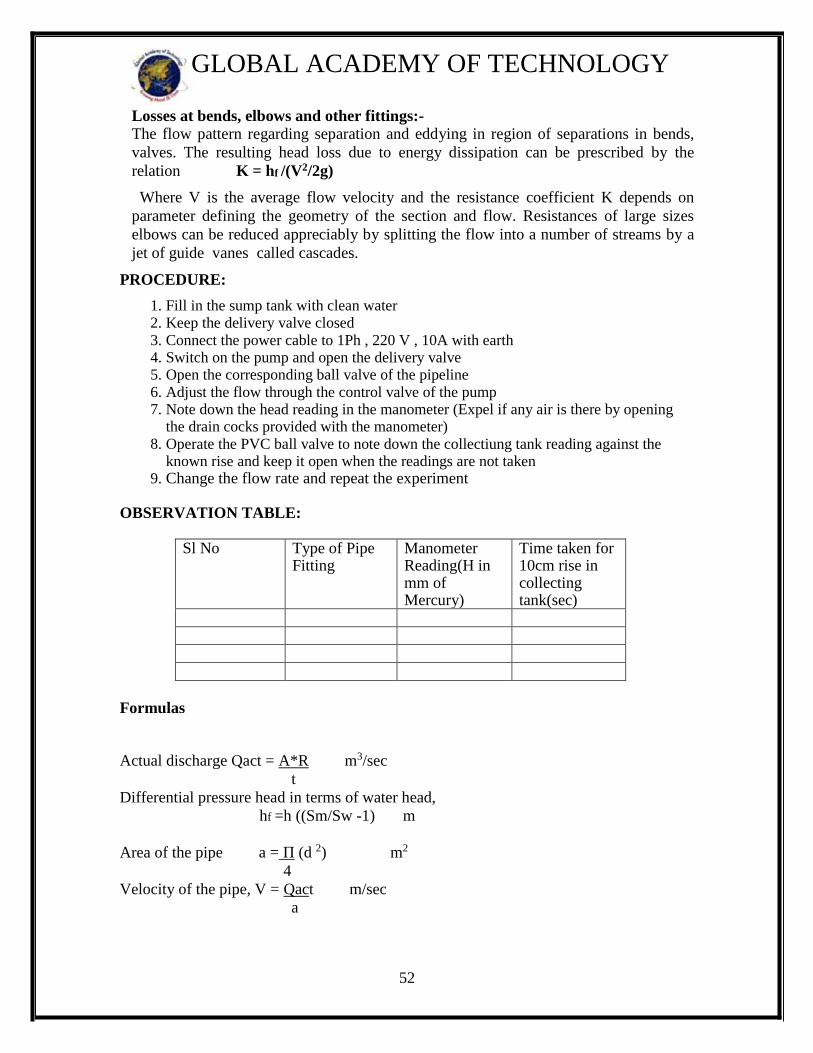
Losses at bends, elbows and other fittings:-
The flow pattern regarding separation and eddying in region of separations in bends,
valves. The resulting head loss due to energy dissipation can be prescribed by the
relation K = hf /(V2/2g)
Where V is the average flow velocity and the resistance coefficient K depends on
parameter defining the geometry of the section and flow. Resistances of large sizes
elbows can be reduced appreciably by splitting the flow into a number of streams by a
jet of guide vanes called cascades.
PROCEDURE:
1. Fill in the sump tank with clean water 2. Keep the delivery valve closed
3. Connect the power cable to 1Ph , 220 V , 10A with earth 4. Switch on the pump and open the delivery valve 5. Open the corresponding ball valve of the pipeline 6. Adjust the flow through the control valve of the pump 7. Note down the head reading in the manometer (Expel if any air is there by opening
the drain cocks provided with the manometer) 8. Operate the PVC ball valve to note down the collectiung tank reading against the
known rise and keep it open when the readings are not taken 9. Change the flow rate and repeat the experiment
OBSERVATION TABLE:
Sl No Type of Pipe Fitting
Manometer Reading(H in mm of Mercury)
Time taken for 10cm rise in collecting tank(sec)
Formulas
Actual discharge Qact = A*R m3/sec
t
Differential pressure head in terms of water head,
hf =h ((Sm/Sw -1) m
Area of the pipe a = Π (d 2) m2
4
Velocity of the pipe, V = Qact m/sec
a

53
GLOBAL ACADEMY OF TECHNOLOGY
Sudden Enlargement
K = hf /((V1-V2)2/2g))
Sudden Contraction
K = hf /((0.5 V2)2/2g))
Losses at bends, elbows and other fittings:-
K = hf /(V2/2g)
Result :

54
GLOBAL ACADEMY OF TECHNOLOGY
WORKSHEET
55
GLOBAL ACADEMY OF TECHNOLOGY
EXPERIMENT NO.12
OGEE WEIR
AIM: To calibrate the ogee weir and hence to determine the value of Cd
APPARATUS:
1. A constant steady water supply with a means of varying the flow
2. An approach channel (flume)
3. ogee weir (to be calibrated)
4. A flow rate measuring facility ((calibrated rectangular notch)
5. Hook gauge
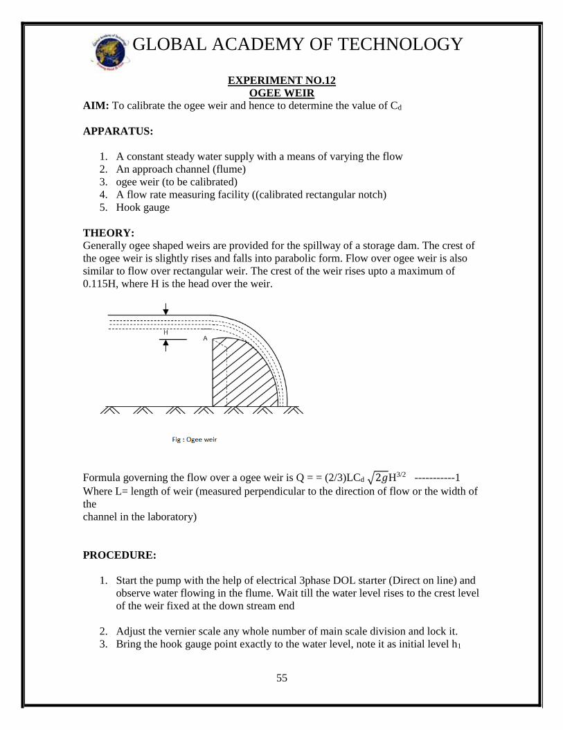
THEORY: Generally ogee shaped weirs are provided for the spillway of a storage dam. The crest of
the ogee weir is slightly rises and falls into parabolic form. Flow over ogee weir is also
similar to flow over rectangular weir. The crest of the weir rises upto a maximum of
0.115H, where H is the head over the weir.
Formula governing the flow over a ogee weir is Q = = (2/3)LCd √2𝑔H3/2 -----------1
Where L= length of weir (measured perpendicular to the direction of flow or the width of
the
channel in the laboratory)
PROCEDURE:
1. Start the pump with the help of electrical 3phase DOL starter (Direct on line) and
observe water flowing in the flume. Wait till the water level rises to the crest level
of the weir fixed at the down stream end
2. Adjust the vernier scale any whole number of main scale division and lock it.
3. Bring the hook gauge point exactly to the water level, note it as initial level h1
56
GLOBAL ACADEMY OF TECHNOLOGY
4. measure the discharge flowing over the ogee weir note it as h2
5. Procedure was repeated for different discharges.
OBSERVATION AND CALCULATIONS
Calculations:(any one trial)
Qthe =(2/3) √2𝑔 LH3/2
Qact = Rotameter reading in m3 / sec
Cd= Qact / Qthe
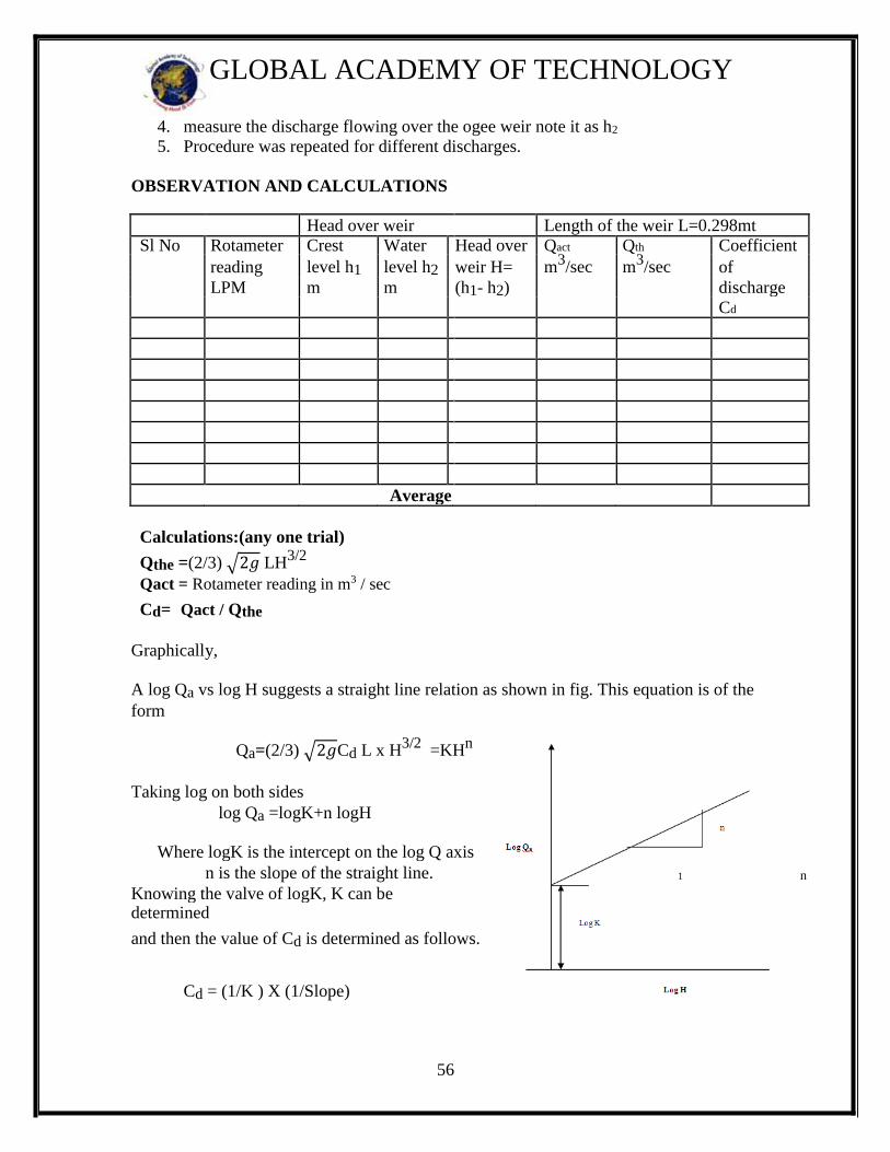
Graphically,
A log Qa vs log H suggests a straight line relation as shown in fig. This equation is of the
form
Qa=(2/3) √2𝑔Cd L x H3/2
=KHn
Taking log on both sides
log Qa =logK+n logH
Where logK is the intercept on the log Q axis
n is the slope of the straight line. n
Knowing the valve of logK, K can be
determined
and then the value of Cd is determined as follows. 1
Cd = (1/K ) X (1/Slope)
Head over weir Length of the weir L=0.298mt
Sl No Rotameter Crest Water Head over Qact Qth Coefficient
reading level h1 level h2 weir H= m3/sec m
3/sec of
LPM m m (h1- h2) discharge Cd
Average

57
GLOBAL ACADEMY OF TECHNOLOGY
Result: Coefficient of discharge (graphical) =-----------------------
Coefficient of discharge (analytical)=............................

58
GLOBAL ACADEMY OF TECHNOLOGY
WORKSHEET

59
GLOBAL ACADEMY OF TECHNOLOGY
EXPERIMENT NO 13
FRANCIS TURBINE
AIM : To conduct Performance test and to determine the efficiency of a Francis Turbine
APPARATUS: Francis Turbine, Digital speed indicator, Pressure gauge, Vacuum gauge,
weights, brake dynamometer, Venturimeter and centrifugal pump.
THEORY: The Francis Turbine operates under medium heads and large quantities of
flow. The water from the pump enters through the spiral casing into the guide vanes and
then to the runner. While passing through the spiral casing and guide vanes a portion of
the pressure head is converted into kinetic energy. The water enters the runner at a higher
velocity than in the pipe line.
Experimentally, the efficiency is determined in the same way as for Pelton or Kaplan
Turbines.
THEORY:
The Francis turbine is a reaction turbine, which means that the working fluid changes
pressure as it moves through the turbine, giving up its energy. A casement is needed to contain the water flow. The turbine is located between the high pressure water source and
the low pressure water exit, usually at the base of a dam. The inlet is spiral shaped. Guide vanes direct the water tangentially to the runner. This radial flow acts on the runner vanes, causing the runner to spin. The guide vanes (or wicket gate) may be adjustable to allow efficient turbine operation for a range of water
flow conditions. As the water moves through the runner its spinning radius decreases, further acting on the
runner. Imagine swinging a ball on a string around in a circle. If the string is pulled short,
the ball spins faster. This property, in addition to the water's pressure, helps inward flow
turbines harness water energy.At the exit, water acts on cup shaped runner features,
leaving with no swirl and very little kinetic or potential energy. The turbine's exit tube is
shaped to help decelerate the water flow and recover the pressure.
CONSTRUCTION SPECIFICATION:
B. Spiral Casing : is of close grained cast iron.
C. Runner: is of gunmetal and nickel plated, designed for efficient operation
accurately machined and smoothly finished.
60
GLOBAL ACADEMY OF TECHNOLOGY
C. Guide Vane Mechanism: Consists of gun metal guide vanes, operated by a hand
wheel through a link mechanism.
D. Shaft: is of EN8 steel accurately machined and provided with a brass and gunmetal
Sleeve at the stuffing box.
E. Ball Bearings: is of double row deep groove rigid type in the casing
And double row self aligning type in the bearing pedestal both of
Liberal size.
F. Draught Bend: is provided at the exit of the runner. To the bend is
connected, a straight conical draught tube of steel fabrication.
G. Brake Arrangement: Consisting of a machined and polished cast iron
brake drum, cooling water pipes,
Standard cast iron dead weights, spring balance, rope brake etc.
arranged for loading the turbine.
J. Sump Tank: approximately about 1000 ltr stainless steel tank is provided for
closed circuit operation.
TECHNICAL SPECIFICATION:
01. Rated Supply Head : 20 meters approximately
02. Rated Speed : 1000 rpm
03. Power Output : 1kW
04. Runaway Speed : 1750 RPM
05. Runner Diameter : 160 mm
06. No. of guide vanes : 10
07. P.C.D. guide vanes : 230mm
08. Brake Drum Diameter : 360 mm
09. Rope Diameter : 16 mm
SUPPLY PUMP SET
01. Rated Head : 26 meters
02. Discharge : 14 LPS approximately
03. Normal Speed : 2880 RPM
04. Power Required :7.5 HP
05. Size of Pump : 80 mm x 65 mm
06. Type : Centrifugal medium speed, single suction
volute
61
GLOBAL ACADEMY OF TECHNOLOGY
FLOW MEASURING UNIT :
01. Inlet diameter of venturimeter : 65mm
02. venturimeter throat Diameter : 35 mm
03. Pressure Gauges : 0-4 Kg/cm2
PROCEDURE:-
1. Connect the power supply to the pump
2. Close the turbine inlet gate valve fully before starting the pump
3. Start the centrifugal pump.
4. Allow the water to flow into the turbine by opening the gate valve.
5. Keep the guide vane at desired value where we get max rpm or head
6. Then close the gate valve so as to attain 1000 or 1200 rpm
7. Allow it to stabilize at that speed
8. Load the turbine gradually say ¼, ½, 3/ 4 & full load by maintaining the turbine
speed 1000RPM by operating the gate valve.
9. Note down the all the parameters as per the tabulation column given below
10. Repeat the experiment for different loads.
11. After the experiment remove the load on the weight hanger and close the gate
valve
12. Stop the pump motor.
13. Calculate the power input, power output and efficiency.
CALCULATIONS:-
In the experimental setup the discharge is measured by means of a venture meter. If a1
and a2 are the areas of cross section at locations 1 and 2 respectively and C is the co-
efficient of venture meter, then it can be shown that
Qa = C x Qth
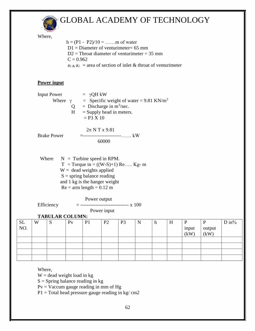
62
GLOBAL ACADEMY OF TECHNOLOGY
Where,
h = (P1 - P2)/10 = ……m of water
D1 = Diameter of venturimeter= 65 mm
D2 = Throat diameter of venturimeter = 35 mm
C = 0.962
a1 & a2 = area of section of inlet & throat of venturimeter
Power input
Input Power = QH kW
Where = Specific weight of water = 9.81 KN/m3
Q = Discharge in m3/sec.
H = Supply head in meters.
= P3 X 10
2 N T x 9.81
Brake Power =-----------------------…… kW
60000
Where N = Turbine speed in RPM.
T = Torque in = ((W-S)+1) Re….. Kg- m
W = dead weights applied
S = spring balance reading
and 1 kg is the hanger weight
Re = arm length = 0.12 m
Power output
Efficiency = ----------------------------- x 100
Power input
TABULAR COLUMN:
SL
NO.
W
S
Pv P1 P2 P3 N h H P
input
(kW)
P
output
(kW)
Ŋ in%
Where,
W = dead weight load in kg
S = Spring balance reading in kg
Pv = Vaccum gauge reading in mm of Hg
P1 = Total head pressure gauge reading in kg/ cm2

63
GLOBAL ACADEMY OF TECHNOLOGY
P2 = Pressure at venture inlet in kg/ cm2
P3 = Pressure at venture throat in kg/ cm2
N = speed of the turbine
h = venturi head in meter of water
H = total head in meter of water
Graph : Plot the graph of Output Versus Input
Results :
Efficiency of Kaplan Turbine graphically=
Efficiency Kaplan Turbine Analytically =