
Giving It All We Go t - NSI Fleetnsifleet.com/pdf/OEM-Industral_VDO_catalog.pdf · Giving It All We...
44
Giving It All We Got . . . Special OEM Catalog Catalog # 010201
Transcript of Giving It All We Go t - NSI Fleetnsifleet.com/pdf/OEM-Industral_VDO_catalog.pdf · Giving It All We...
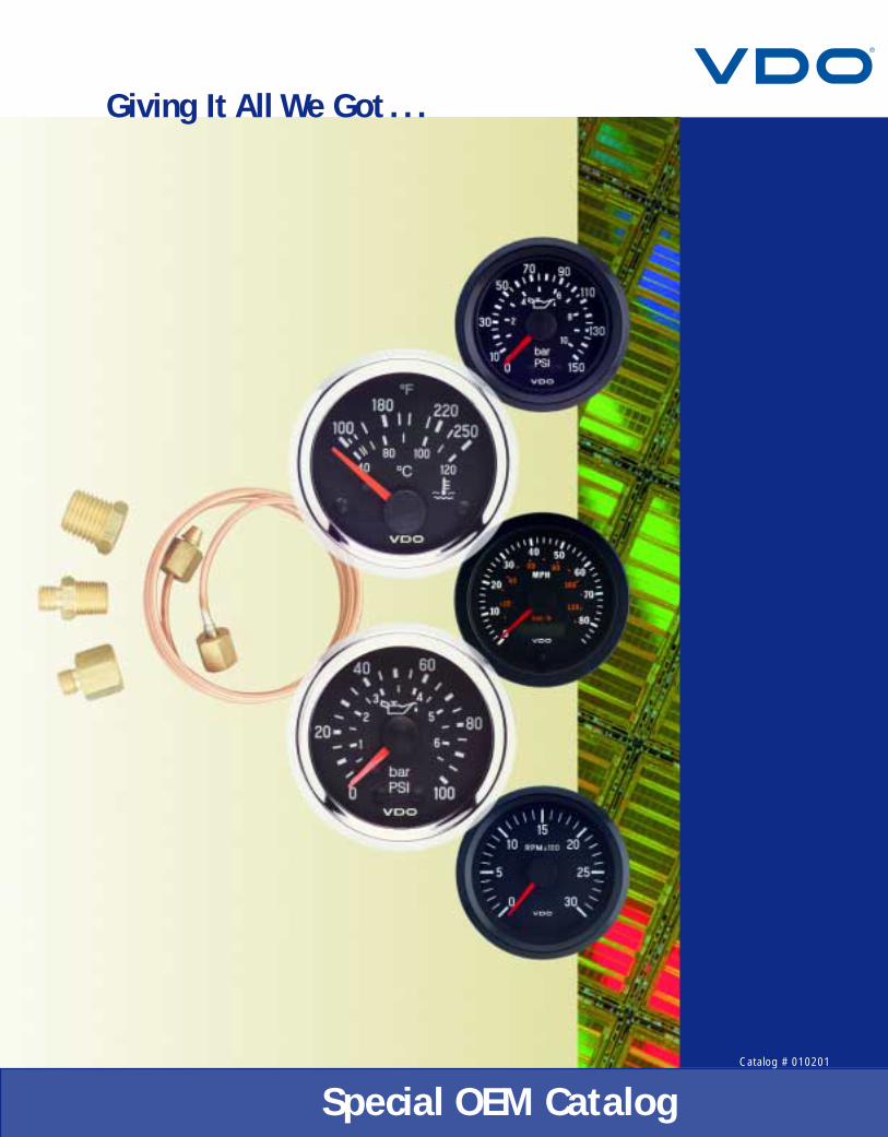
Giving It All We Got . . .
Special OEM CatalogCatalog # 010201

Over 500 employees work in VDO’s 210,000 sq.ft.state-of-the-art manufacturing facility in Winchester, VA.
Coming Through for the CustomerVDO designs, engineers and manufactures instruments,
instrument clusters, electronic information systems, sensors and
control systems for a wide variety of vehicles and equipment.
As a leader in electronic instrumentation, control and sensor
technologies, VDO pioneered innovations such as electronic
speedometers, multi-function displays, sensors and
electronic engine management controls.
VDO provides its customers with a true international resource.
Worldwide, VDO has over 30 manufacturing plants and
employs over 120,000 people. Strength afforded by this global
position also allows VDO to maintain extensive research and
development capabilities around the world. As a vertically
integrated company, VDO is able to provide customers with
complete, cost effective solutions from concept through
production. Around the world, VDO products and
systems enjoy a reputation for accuracy and reliability.
VDO is ready. With ISO 9001 and QS 9000 accreditation,
four production facilities and a Technical Center in
North America, we look froward to helping you meet the
challenges of the increasing competitive worldwide markets.

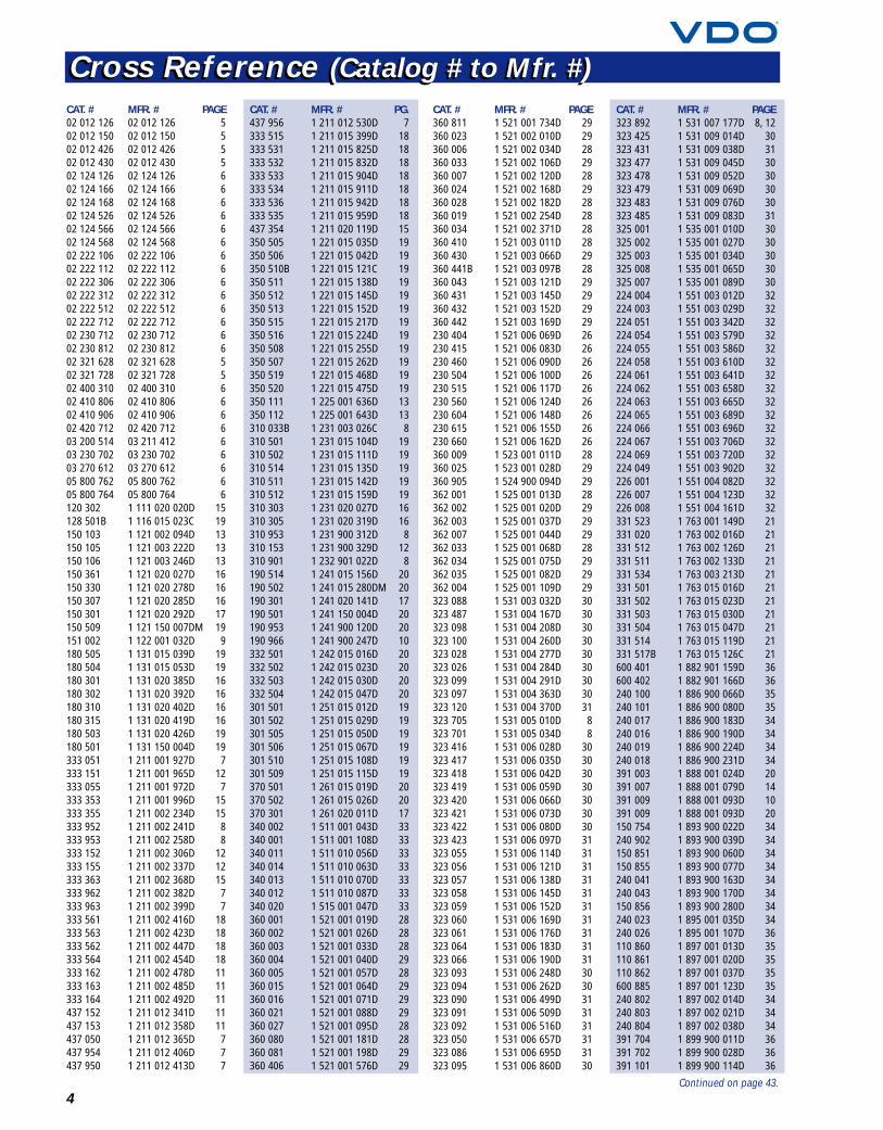
Table of ContentsCross Reference (Catalog # to Mfr. #) 4
(continued on page 43)
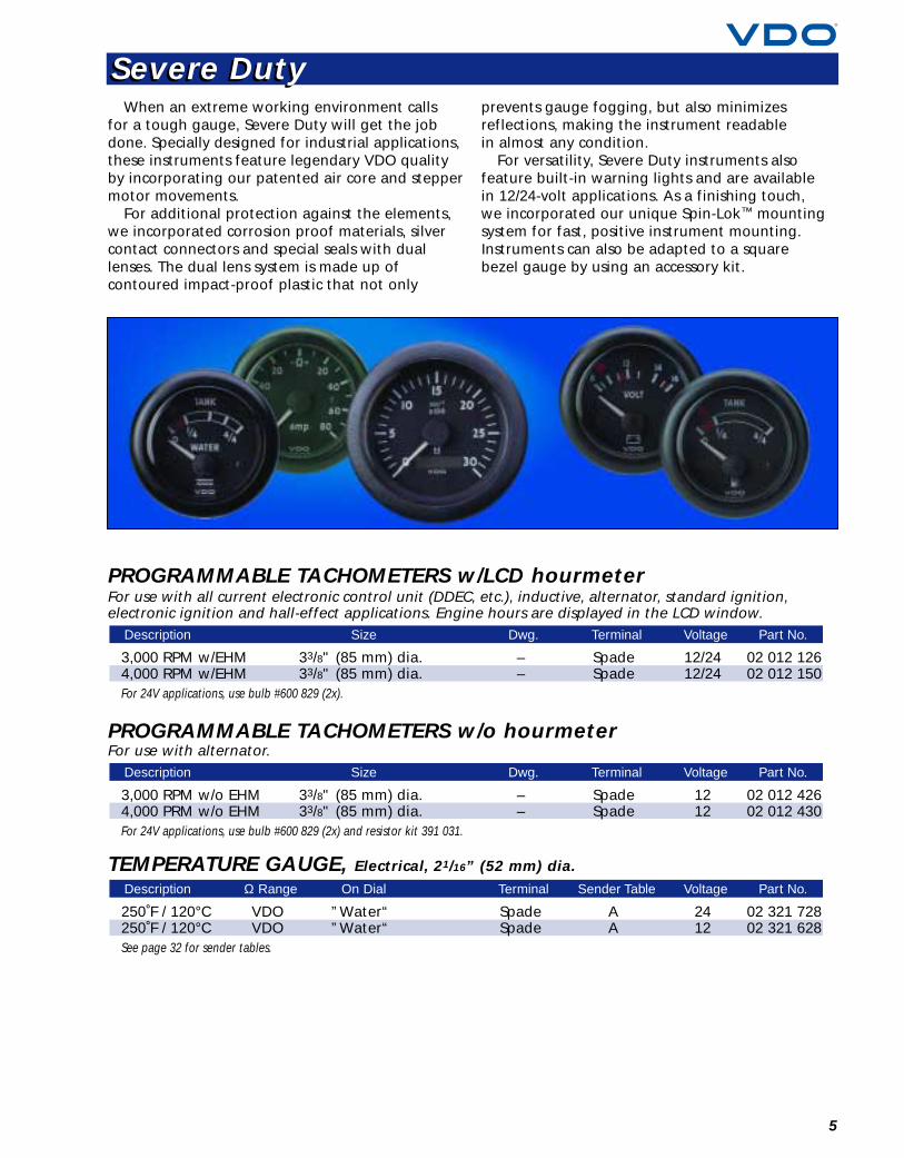
Severe Duty 5
Cockpit International 7
Vision 11
Series 1 15
Industrial 18
DC Hourmeters 21
BAI System 22
D’Mac System 23
E-Gas Electronic Actuator System 24
Windshield Washer System 25
230 Series Heavy-Duty Pressure Switch 26
232 Series Temperature Switches 27
Pressure Senders 28
Temperature Senders 30
Fuel Level Senders 32
Speedometer & Tachometer Senders 33
Gauge Accessories 34
Light Bulbs and Sockets 37
Technical Specifications and Dimensions 39
VDO Limited WarrantyVDO North America warrants all merchandise against defect in factory workmanship and materials fora period of 24 months after purchase. This warranty applies to the first retail purchaser and covers onlythose products exposed to normal use or service. Provisions of this warranty shall not apply to a VDOproduct used for a purpose for which it was not designed, or which has been altered in any way thatwould be detrimental to the performance or life of the product, or misapplication, misuse, negligenceor accident. On any part or product found to be defective after examination by VDO North America,VDO North America will only repair or replace the merchandise through the original selling dealer oron a direct basis. VDO North America assumes no responsibility for diagnosis, removal and/or installationlabor, loss of vehicle use, loss of time, inconvenience or any other consequential expenses. The warrantiesherein are in lieu of any other expressed or implied warranties, including any implied warranty ofmerchantability or fitness, and any other obligation on the part of VDO North America, or selling dealer.Note: This is a “Limited Warranty” as defined by the Magnuson-Moss Warranty Act of 1975.
4
Cross Reference (Catalog # to Mfr. #)Cross Reference (Catalog # to Mfr. #)CAT. # MFR. # PAGE02 012 126 02 012 126 502 012 150 02 012 150 502 012 426 02 012 426 502 012 430 02 012 430 502 124 126 02 124 126 602 124 166 02 124 166 602 124 168 02 124 168 602 124 526 02 124 526 602 124 566 02 124 566 602 124 568 02 124 568 602 222 106 02 222 106 602 222 112 02 222 112 602 222 306 02 222 306 602 222 312 02 222 312 602 222 512 02 222 512 602 222 712 02 222 712 602 230 712 02 230 712 602 230 812 02 230 812 602 321 628 02 321 628 502 321 728 02 321 728 502 400 310 02 400 310 602 410 806 02 410 806 602 410 906 02 410 906 602 420 712 02 420 712 603 200 514 03 211 412 603 230 702 03 230 702 603 270 612 03 270 612 605 800 762 05 800 762 605 800 764 05 800 764 6120 302 1 111 020 020D 15128 501B 1 116 015 023C 19150 103 1 121 002 094D 13150 105 1 121 003 222D 13150 106 1 121 003 246D 13150 361 1 121 020 027D 16150 330 1 121 020 278D 16150 307 1 121 020 285D 16150 301 1 121 020 292D 17150 509 1 121 150 007DM 19151 002 1 122 001 032D 9180 505 1 131 015 039D 19180 504 1 131 015 053D 19180 301 1 131 020 385D 16180 302 1 131 020 392D 16180 310 1 131 020 402D 16180 315 1 131 020 419D 16180 503 1 131 020 426D 19180 501 1 131 150 004D 19333 051 1 211 001 927D 7333 151 1 211 001 965D 12333 055 1 211 001 972D 7333 353 1 211 001 996D 15333 355 1 211 002 234D 15333 952 1 211 002 241D 8333 953 1 211 002 258D 8333 152 1 211 002 306D 12333 155 1 211 002 337D 12333 363 1 211 002 368D 15333 962 1 211 002 382D 7333 963 1 211 002 399D 7333 561 1 211 002 416D 18333 563 1 211 002 423D 18333 562 1 211 002 447D 18333 564 1 211 002 454D 18333 162 1 211 002 478D 11333 163 1 211 002 485D 11333 164 1 211 002 492D 11437 152 1 211 012 341D 11437 153 1 211 012 358D 11437 050 1 211 012 365D 7437 954 1 211 012 406D 7437 950 1 211 012 413D 7
CAT. # MFR. # PG.437 956 1 211 012 530D 7333 515 1 211 015 399D 18333 531 1 211 015 825D 18333 532 1 211 015 832D 18333 533 1 211 015 904D 18333 534 1 211 015 911D 18333 536 1 211 015 942D 18333 535 1 211 015 959D 18437 354 1 211 020 119D 15350 505 1 221 015 035D 19350 506 1 221 015 042D 19350 510B 1 221 015 121C 19350 511 1 221 015 138D 19350 512 1 221 015 145D 19350 513 1 221 015 152D 19350 515 1 221 015 217D 19350 516 1 221 015 224D 19350 508 1 221 015 255D 19350 507 1 221 015 262D 19350 519 1 221 015 468D 19350 520 1 221 015 475D 19350 111 1 225 001 636D 13350 112 1 225 001 643D 13310 033B 1 231 003 026C 8310 501 1 231 015 104D 19310 502 1 231 015 111D 19310 514 1 231 015 135D 19310 511 1 231 015 142D 19310 512 1 231 015 159D 19310 303 1 231 020 027D 16310 305 1 231 020 319D 16310 953 1 231 900 312D 8310 153 1 231 900 329D 12310 901 1 232 901 022D 8190 514 1 241 015 156D 20190 502 1 241 015 280DM 20190 301 1 241 020 141D 17190 501 1 241 150 004D 20190 953 1 241 900 120D 20190 966 1 241 900 247D 10332 501 1 242 015 016D 20332 502 1 242 015 023D 20332 503 1 242 015 030D 20332 504 1 242 015 047D 20301 501 1 251 015 012D 19301 502 1 251 015 029D 19301 505 1 251 015 050D 19301 506 1 251 015 067D 19301 510 1 251 015 108D 19301 509 1 251 015 115D 19370 501 1 261 015 019D 20370 502 1 261 015 026D 20370 301 1 261 020 011D 17340 002 1 511 001 043D 33340 001 1 511 001 108D 33340 011 1 511 010 056D 33340 014 1 511 010 063D 33340 013 1 511 010 070D 33340 012 1 511 010 087D 33340 020 1 515 001 047D 33360 001 1 521 001 019D 28360 002 1 521 001 026D 28360 003 1 521 001 033D 28360 004 1 521 001 040D 29360 005 1 521 001 057D 28360 015 1 521 001 064D 29360 016 1 521 001 071D 29360 021 1 521 001 088D 29360 027 1 521 001 095D 28360 080 1 521 001 181D 28360 081 1 521 001 198D 29360 406 1 521 001 576D 29
CAT. # MFR. # PAGE360 811 1 521 001 734D 29360 023 1 521 002 010D 29360 006 1 521 002 034D 28360 033 1 521 002 106D 29360 007 1 521 002 120D 28360 024 1 521 002 168D 29360 028 1 521 002 182D 28360 019 1 521 002 254D 28360 034 1 521 002 371D 28360 410 1 521 003 011D 28360 430 1 521 003 066D 29360 441B 1 521 003 097B 28360 043 1 521 003 121D 29360 431 1 521 003 145D 29360 432 1 521 003 152D 29360 442 1 521 003 169D 29230 404 1 521 006 069D 26230 415 1 521 006 083D 26230 460 1 521 006 090D 26230 504 1 521 006 100D 26230 515 1 521 006 117D 26230 560 1 521 006 124D 26230 604 1 521 006 148D 26230 615 1 521 006 155D 26230 660 1 521 006 162D 26360 009 1 523 001 011D 28360 025 1 523 001 028D 29360 905 1 524 900 094D 29362 001 1 525 001 013D 28362 002 1 525 001 020D 29362 003 1 525 001 037D 29362 007 1 525 001 044D 29362 033 1 525 001 068D 28362 034 1 525 001 075D 29362 035 1 525 001 082D 29362 004 1 525 001 109D 29323 088 1 531 003 032D 30323 487 1 531 004 167D 30323 098 1 531 004 208D 30323 100 1 531 004 260D 30323 028 1 531 004 277D 30323 026 1 531 004 284D 30323 099 1 531 004 291D 30323 097 1 531 004 363D 30323 120 1 531 004 370D 31323 705 1 531 005 010D 8323 701 1 531 005 034D 8323 416 1 531 006 028D 30323 417 1 531 006 035D 30323 418 1 531 006 042D 30323 419 1 531 006 059D 30323 420 1 531 006 066D 30323 421 1 531 006 073D 30323 422 1 531 006 080D 30323 423 1 531 006 097D 31323 055 1 531 006 114D 31323 056 1 531 006 121D 31323 057 1 531 006 138D 31323 058 1 531 006 145D 31323 059 1 531 006 152D 31323 060 1 531 006 169D 31323 061 1 531 006 176D 31323 064 1 531 006 183D 31323 066 1 531 006 190D 31323 093 1 531 006 248D 30323 094 1 531 006 262D 30323 090 1 531 006 499D 31323 091 1 531 006 509D 31323 092 1 531 006 516D 31323 050 1 531 006 657D 31323 086 1 531 006 695D 31323 095 1 531 006 860D 30
CAT. # MFR. # PAGE323 892 1 531 007 177D 8, 12323 425 1 531 009 014D 30323 431 1 531 009 038D 31323 477 1 531 009 045D 30323 478 1 531 009 052D 30323 479 1 531 009 069D 30323 483 1 531 009 076D 30323 485 1 531 009 083D 31325 001 1 535 001 010D 30325 002 1 535 001 027D 30325 003 1 535 001 034D 30325 008 1 535 001 065D 30325 007 1 535 001 089D 30224 004 1 551 003 012D 32224 003 1 551 003 029D 32224 051 1 551 003 342D 32224 054 1 551 003 579D 32224 055 1 551 003 586D 32224 058 1 551 003 610D 32224 061 1 551 003 641D 32224 062 1 551 003 658D 32224 063 1 551 003 665D 32224 065 1 551 003 689D 32224 066 1 551 003 696D 32224 067 1 551 003 706D 32224 069 1 551 003 720D 32224 049 1 551 003 902D 32226 001 1 551 004 082D 32226 007 1 551 004 123D 32226 008 1 551 004 161D 32331 523 1 763 001 149D 21331 020 1 763 002 016D 21331 512 1 763 002 126D 21331 511 1 763 002 133D 21331 534 1 763 003 213D 21331 501 1 763 015 016D 21331 502 1 763 015 023D 21331 503 1 763 015 030D 21331 504 1 763 015 047D 21331 514 1 763 015 119D 21331 517B 1 763 015 126C 21600 401 1 882 901 159D 36600 402 1 882 901 166D 36240 100 1 886 900 066D 35240 101 1 886 900 080D 35240 017 1 886 900 183D 34240 016 1 886 900 190D 34240 019 1 886 900 224D 34240 018 1 886 900 231D 34391 003 1 888 001 024D 20391 007 1 888 001 079D 14391 009 1 888 001 093D 10391 009 1 888 001 093D 20150 754 1 893 900 022D 34240 902 1 893 900 039D 34150 851 1 893 900 060D 34150 855 1 893 900 077D 34240 041 1 893 900 163D 34240 043 1 893 900 170D 34150 856 1 893 900 280D 34240 023 1 895 001 035D 34240 026 1 895 001 107D 36110 860 1 897 001 013D 35110 861 1 897 001 020D 35110 862 1 897 001 037D 35600 885 1 897 001 123D 35240 802 1 897 002 014D 34240 803 1 897 002 021D 34240 804 1 897 002 038D 34391 704 1 899 900 011D 36391 702 1 899 900 028D 36391 101 1 899 900 114D 36
Continued on page 43.
5
When an extreme working environment callsfor a tough gauge, Severe Duty will get the jobdone. Specially designed for industrial applications,these instruments feature legendary VDO qualityby incorporating our patented air core and steppermotor movements.
For additional protection against the elements,we incorporated corrosion proof materials, silvercontact connectors and special seals with duallenses. The dual lens system is made up ofcontoured impact-proof plastic that not only
prevents gauge fogging, but also minimizesreflections, making the instrument readablein almost any condition.
For versatility, Severe Duty instruments alsofeature built-in warning lights and are availablein 12/24-volt applications. As a finishing touch,we incorporated our unique Spin-Lok™ mountingsystem for fast, positive instrument mounting.Instruments can also be adapted to a squarebezel gauge by using an accessory kit.
PROGRAMMABLE TACHOMETERS w/LCD hourmeterFor use with all current electronic control unit (DDEC, etc.), inductive, alternator, standard ignition,electronic ignition and hall-effect applications. Engine hours are displayed in the LCD window.
3,000 RPM w/EHM 33/8" (85 mm) dia. – Spade 12/24 02 012 1264,000 RPM w/EHM 33/8" (85 mm) dia. – Spade 12/24 02 012 150For 24V applications, use bulb #600 829 (2x).
PROGRAMMABLE TACHOMETERS w/o hourmeterFor use with alternator.
3,000 RPM w/o EHM 33/8" (85 mm) dia. – Spade 12 02 012 4264,000 PRM w/o EHM 33/8" (85 mm) dia. – Spade 12 02 012 430For 24V applications, use bulb #600 829 (2x) and resistor kit 391 031.
TEMPERATURE GAUGE, Electrical, 21/16” (52 mm) dia.
250˚F / 120°C VDO ”Water“ Spade A 24 02 321 728250˚F / 120°C VDO ”Water“ Spade A 12 02 321 628See page 32 for sender tables.
Description Ω Range On Dial Terminal Sender Table Voltage Part No.
Description Size Dwg. Terminal Voltage Part No.
Description Size Dwg. Terminal Voltage Part No.
Severe DutySevere Duty
6
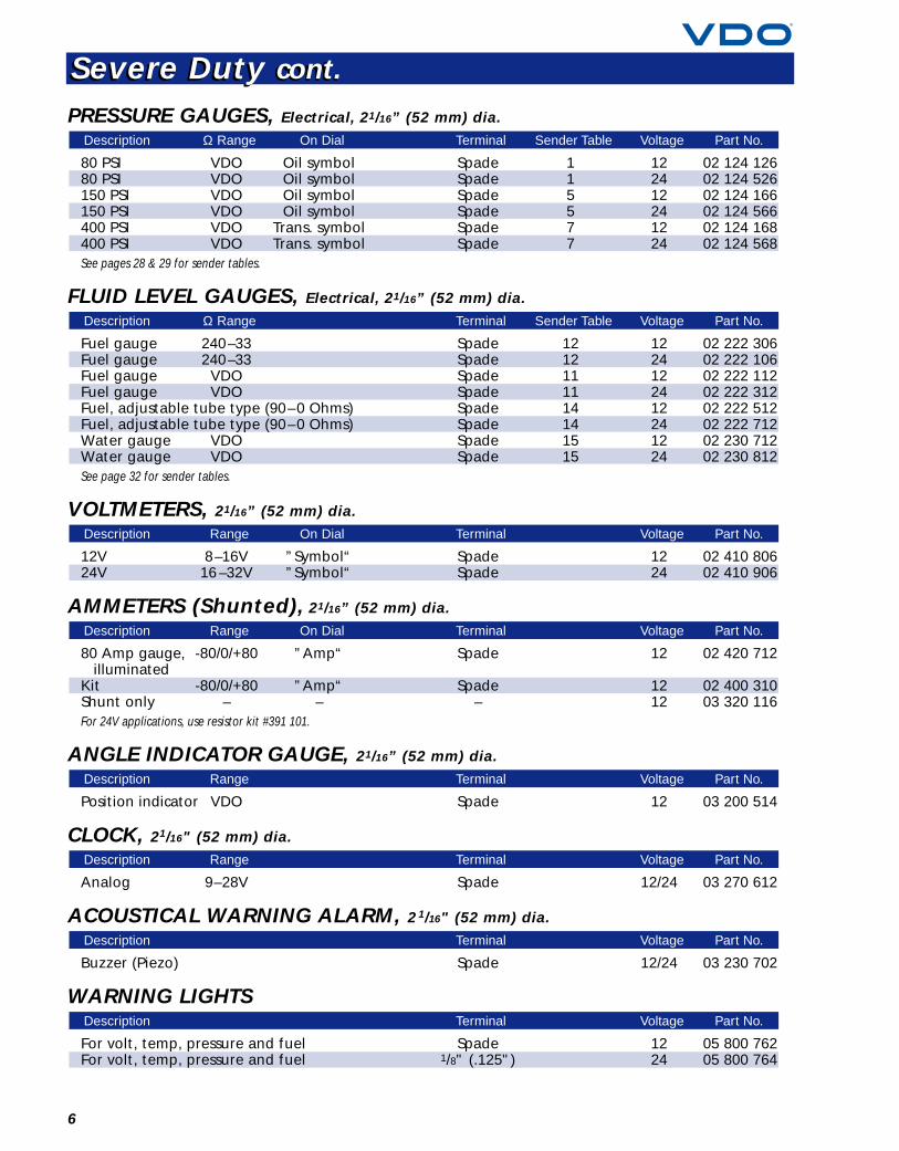
PRESSURE GAUGES, Electrical, 21/16” (52 mm) dia.
80 PSI VDO Oil symbol Spade 1 12 02 124 12680 PSI VDO Oil symbol Spade 1 24 02 124 526150 PSI VDO Oil symbol Spade 5 12 02 124 166150 PSI VDO Oil symbol Spade 5 24 02 124 566400 PSI VDO Trans. symbol Spade 7 12 02 124 168400 PSI VDO Trans. symbol Spade 7 24 02 124 568See pages 28 & 29 for sender tables.
FLUID LEVEL GAUGES, Electrical, 21/16” (52 mm) dia.
Fuel gauge 240–33 Spade 12 12 02 222 306Fuel gauge 240–33 Spade 12 24 02 222 106Fuel gauge VDO Spade 11 12 02 222 112Fuel gauge VDO Spade 11 24 02 222 312Fuel, adjustable tube type (90–0 Ohms) Spade 14 12 02 222 512Fuel, adjustable tube type (90–0 Ohms) Spade 14 24 02 222 712Water gauge VDO Spade 15 12 02 230 712Water gauge VDO Spade 15 24 02 230 812See page 32 for sender tables.
VOLTMETERS, 21/16” (52 mm) dia.
12V 8–16V ”Symbol“ Spade 12 02 410 80624V 16 –32V ”Symbol“ Spade 24 02 410 906
AMMETERS (Shunted), 21/16” (52 mm) dia.
80 Amp gauge, -80/0/+80 ”Amp“ Spade 12 02 420 712illuminated
Kit -80/0/+80 ”Amp“ Spade 12 02 400 310Shunt only – – – 12 03 320 116For 24V applications, use resistor kit #391 101.
ANGLE INDICATOR GAUGE, 21/16” (52 mm) dia.
Position indicator VDO Spade 12 03 200 514
CLOCK, 21/16" (52 mm) dia.
Analog 9–28V Spade 12/24 03 270 612
ACOUSTICAL WARNING ALARM, 21/16" (52 mm) dia.
Buzzer (Piezo) Spade 12/24 03 230 702
WARNING LIGHTS
For volt, temp, pressure and fuel Spade 12 05 800 762For volt, temp, pressure and fuel 1/8" (.125") 24 05 800 764
Description Terminal Voltage Part No.
Description Terminal Voltage Part No.
Description Range Terminal Voltage Part No.
Description Range Terminal Voltage Part No.
Description Range On Dial Terminal Voltage Part No.
Description Range On Dial Terminal Voltage Part No.
Description Ω Range Terminal Sender Table Voltage Part No.
Description Ω Range On Dial Terminal Sender Table Voltage Part No.
Severe Duty cont.Severe Duty cont.
7For technical specifications and dimensions, see pages 38–42.
These world-class instruments are designed tobe the standard in the industry at an economicalprice. All instruments feature VDO’s latestgeneration patented air core and steeper motormovements for the reliability and durability you’vecome to expect from a leader in instrumentation.
These instruments are made for durability with
a choice of two terminals: M4 studs and .250"male spade. All 52 mm instruments feature zinc-plated metal housing and black painted, brassbezels for rugged, reliable service.
Each instrument in this product line incorporatesstandard flood-lit illumination and is available in12/24-volt applications.
PROGRAMMABLE SPEEDOMETERS w/resettable LCD tripodometerFeature a unique auto-calibration function for easy adjustment through the LCD display. Odometerand trip odometer are clearly displayed in the LCD window.
For use with hall-effect, inductive, OEM electronic output and generator senders.
120 MPH 31/8" (80 mm) dia. A Spade 12 437 05045 MPH / 75 KMH 33/8" (85 mm) dia. A Spade 12 437 950130 KMH / 85 MPH 33/8" (85 mm) dia. A Spade 12 437 956120 MPH / 200 KMH 33/8" (85 mm) dia. A Spade 12 437 954120 MPH 33/8" (85 mm) dia. A Spade 12 437 052160 MPH 33/8" (85 mm) dia. A Spade 12 437 053For 24V applications, use bulb #600 826 (2x).
PROGRAMMABLE TACHOMETERS w/LCD hourmeterFor use with all current electronic control unit (DDEC, etc.), inductive, alternator, standard ignition,electronic ignition and hall-effect applications. Engine hours are displayed in the LCD window.
7,000 RPM 31/8" (80 mm) dia. – Spade 12 333 0513,000 RPM 33/8" (85 mm) dia. B Spade 12 333 9624,000 RPM 33/8" (85 mm) dia. B Spade 12 333 9637,000 RPM 33/8" (85 mm) dia. – Spade 12 333 055For 24V applications, use bulb #600 826 (2x).
Description Size Dwg. Terminal Voltage Part No.
Description Size Dwg. Terminal Voltage Part No.
Cockpit InternationalCockpit International
8
Cockpit International cont.Cockpit International cont.
PROGRAMMABLE TACHOMETERS w/o hourmeterFor use with alternator, 4/6/8 cylinder ignition and 12V square wave applications.
4,000 RPM 21/16" (52 mm) dia. D Spade 12 333 9656,000 RPM 21/16" (52 mm) dia. D Spade 12 333 9588,000 RPM 21/16" (52 mm) dia. D Spade 12 333 9593,000 RPM 33/8" (85 mm) dia. C Spade 12 333 9524,000 RPM 33/8" (85 mm) dia. C Spade 12 333 953For 24V applications, use resistor kit #391 101, 2 1/16".For 24V applications, use resistor kit #391 103, 3 3/8".
TEMPERATURE GAUGES, Electrical, 21/16" (52 mm) dia.
240˚F / 110˚C U.S. Water symbol G Stud – 12 310 907250˚F / 120˚C VDO Water symbol G Stud A 12 310 909250˚F VDO “Water” E Spade A 12 310 039250˚F / 120˚C VDO Water symbol G Spade A 12 310 934B280˚F / 140˚C U.S. Water symbol G Stud – 12 310 911300˚F / 150˚C VDO Oil symbol G Stud B 12 310 915300˚F VDO “Oil” E Spade B 12 310 012250˚F / 120˚C VDO Water symbol G Stud A 24 310 910300˚F / 150˚C VDO ”Oil” G Spade B 12 310 936B300˚F / 150˚C VDO Oil symbol G Stud B 24 310 916600˚F VDO Cyl. head temp G Spade – 12 310 033BSee page 30 & 31 for sender tables.
Mechanical, 21/16" (52 mm) dia.
265°F/130°C 72" cap. H 1/2–14 NPT 12 180 901265°F/130°C 96" cap. H 1/2–14 NPT 12 180 902265°F/130°C 144" cap. H 1/2–14 NPT 12 180 903For 24V applications, use bulb #600 826.
Adapters
1/2–14 NPT 180 0663/8 –18 NPT 180 067
Cylinder Head Temperature, 21/16" (52 mm) dia.
600°F, complete kit P 12 310 90114 mm dia. thermal sender (included in kit) – – 323 70112 mm dia. thermal sender – – 323 705For 24V applications, use bulb #600 807.
PYROMETERS, 250˚– 1650˚F, 21/16" (52 mm) dia.
12' kit O 12 310 953Gauge only O 12 310 951Pyrometer sender only O – 323 89230' extension – – 240 092For 24V applications, use resistor kit #391 101.
Description Dwg. Voltage Part No.
Description Dwg. Voltage Part No.
Description Part No.
Description Length Dwg. Fitting Size Voltage Part No.
Description Ω Range On Dial Dwg. Terminal Sender Table Voltage Part No.
Description Size Dwg. Terminal Voltage Part No.
9For technical specifications and dimensions, see pages 38–42.
PRESSURE GAUGES, Electrical, 21/16" (52 mm) dia.
80 PSI / 5 bar VDO Oil symbol G Stud 1 12 350 90180 PSI VDO ”Oil“ E Spade 1 12 350 04080 PSI VDO ”Oil“ E Spade 1 12 350 934B150 PSI / 10 bar VDO Oil symbol G Stud 5 12 350 909150 PSI VDO Air symbol E Spade 5 12 350 041400 PSI VDO Trans. symbol G Stud 7 12 350 91380 PSI / 5 bar VDO Oil symbol G Stud 1 24 350 902150 PSI / 10 bar VDO Oil symbol G Stud 5 24 350 910See pages 28 & 29 for sender tables.
Mechanical, 21/16" (52 mm) dia.
15 PSI ”Boost“ I 1/8–27 NPT 12 150 05130 PSI ”Boost“ I 1/8–27 NPT 12 150 052100 PSI ”Oil“ I 1/8–27 NPT 12 150 030150 PSI / 10 bar Oil symbol I 1/8–27 NPT 12 150 904150 PSI / 10 bar Air symbol I 1/8–27 NPT 12 150 905400 PSI / 25 bar Oil symbol I 1/8–27 NPT 12 150 906For 24V applications, use bulb #600 826.
DUAL AIR PRESSURE GAUGE, Mechanical, 31/8" (80 mm) dia.
Red / Green pointer ”Air“ I 1/8–27 NPT 24 151 002For 12V applications, use bulb #600 803 (2x).
VACUUM, 21/16" (52 mm) dia.
30" Hg. / 1 bar ”Vacuum“ I 1/8–27 NPT 12 150 042For 24V applications, use bulb #600 826.Tubing kit not included, see page 34.
TURBO BOOST, 21/16" (52 mm) dia.
30" Hg. / 20 PSI I 1/8–27 NPT 12 150 921For 24V applications, use bulb #600 826.Tubing kit not included, see page 34.
FUEL LEVEL GAUGES, Electrical, 21/16" (52 mm) dia.
For VDO sender 10 –180 ”Fuel“ E Spade 11 12 301 015For VDO sender 10 –180 symbol G Stud 11 12 301 901For U.S. sender 240 – 33 ”Fuel“ G Stud 12 12 301 903For GM sender, 0 – 90 ”Tank“ E Spade 13 12 301 030
(from 1965)For O.E.M. sender 0 – 90 ”LP“ – Spade N/A 12 301 036For O.E.M. sender 0 – 90 symbol – Spade 13 12 301 930BFor VDO sender 10 –180 symbol G Stud 11 24 301 902For U.S. sender 240 – 33 symbol G Stud 12 24 301 904See page 32 for sender tables.
Description Ω Range On Dial Dwg. Terminal Sender Table Voltage Part No.
Description Dwg. Fitting Size Voltage Part No.
Description On Dial Dwg. Fitting Size Voltage Part No.
Description On Dial Dwg. Fitting Size Voltage Part No.
Description On Dial Dwg. Fitting Size Voltage Part No.
Description Ω Range On Dial Dwg. Terminal Sender Table Voltage Part No.
Cockpit International cont.Cockpit International cont.

10
VOLTMETERS, Electrical, 21/16" (52 mm) dia., w/ISO symbol
12V 8 –16V G Stud 12 332 90112V 8 –16V G Spade 12 332 932B12V, w/colorband 8 –16V E Spade 12 332 04124V 18 – 32V G Stud 24 332 902
AMMETERS (Non-shunted), 21/16" (52 mm) dia.
30 Amp 30/0/30 ”Amp“ L Stud 12 190 90360 Amp 60/0/60 ”Amp“ L Stud 12 190 904For 24V applications, use bulb #600 826.
AMMETER (Shunted), 21/16” (52 mm) dia., complete kit w/shunt
300 Amp kit 300/0/300 ”Amp“ M Spade 12 190 966For 24V applications, use resistor #391 101.
Accessories
300 Amp, shunt only 391 009
CLOCK, 21/16" (52 mm) dia.
Analog 9 – 28V J Spade 12/24 370 951For 24V applications, use bulb #600 807.
Description Range Dwg. Terminal Voltage Part No.
Description Part No.
Description Range On Dial Dwg. Terminal Voltage Part No.
Description Range On Dial Dwg. Terminal Voltage Part No.
Description Range Dwg. Terminal Voltage Part No.
Cockpit International cont.Cockpit International cont.
PROGRAMMABLE SPEEDOMETERS w/resettable LCD tripodometerVision speedometers feature a unique auto-calibration function, allowing for easy adjustmentthrough the LCD display. Odometer and tripodometer are clearly displayed in the LCD window,and the operator may toggle between these modes with the push of a button.
For use with hall-effect, inductive, OEM electronic output and generator senders.
85 MPH / 130 KMH 33/8" (85 mm) dia. A Spade 12/24 437 152120 MPH 33/8" (85 mm) dia. A Spade 12/24 437 153120 MPH 4" (100 mm) dia. A Spade 12/24 437 155For 24V applications, use bulb #600 826 (2x).
PROGRAMMABLE TACHOMETERS w/LCD hourmeterFor use with all current electronic control units (DDEC, etc.), inductive, alternator, standard ignition,electronic ignition and hall-effect applications. Engine hours are displayed in the LCD window.
3,000 RPM 33/8" (85 mm) dia. B Spade 12/24 333 1624,000 RPM 33/8" (85 mm) dia. B Spade 12/24 333 1636,000 RPM 33/8" (85 mm) dia. B Spade 12/24 333 164For 24V applications, use bulb #600 826 (2x).
Description Size Dwg. Terminal Voltage Part No.
Description Size Dwg. Terminal Voltage Part No.
VDO Vision represents a true technologicaladvancement in instrument illumination. Usinglight piping techniques, we have created fully-backlit ”through dial lighting“ and pointerillumination with an unmatched level ofnighttime readability.
Vision instruments also feature our innovativeSpin-Lok™ mounting system for fast and easy
installation. Using our unique spin-on clamp, itprovides a full 360 degrees of mounting forcewhen installed, preventing panel warping andgauge rotation.
As with all VDO instruments, Visionincorporates the use of our own patentedair core or stepper motor movements. Designedand used worldwide exclusively by VDO.
11For technical specifications and dimensions, see pages 38–42.
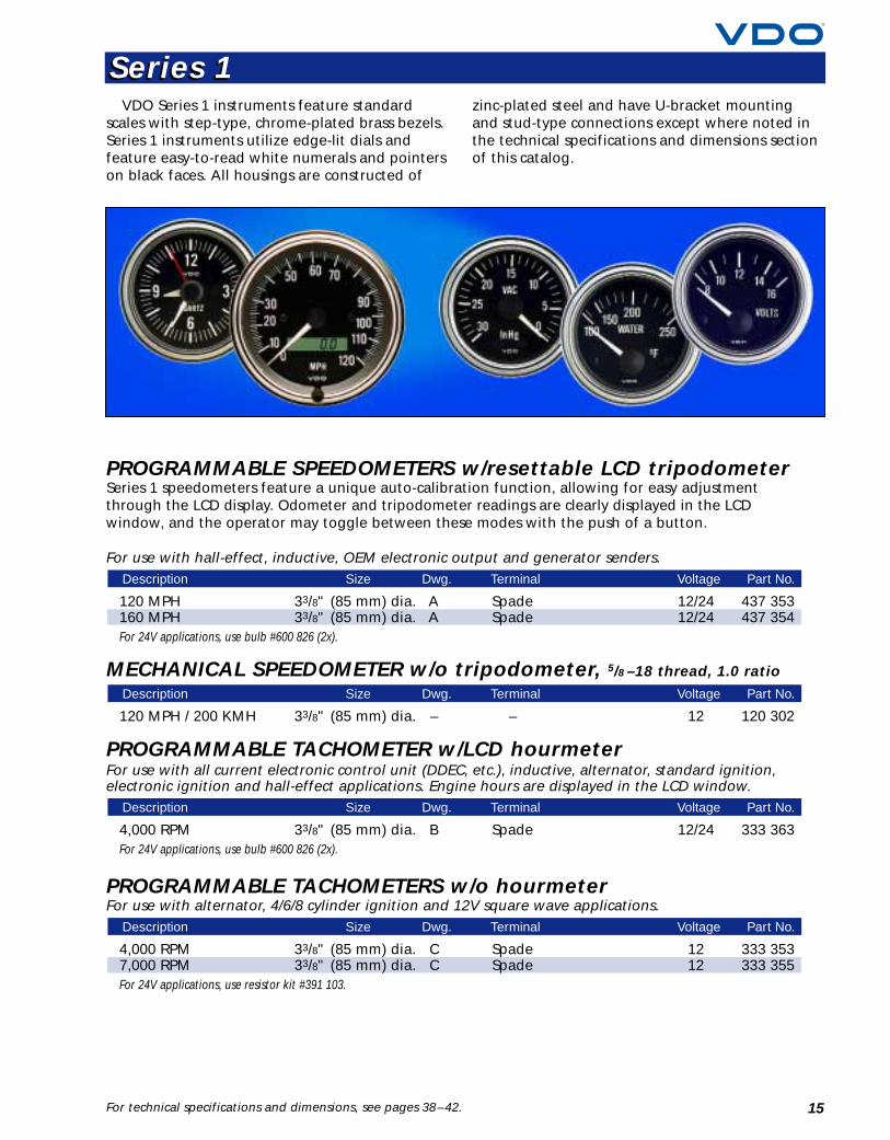
VisionVision
VDO’s Spin-Lok™mounting systemsecures the instrumentwith 360˚ of force.
Trioptic™technology forsuperior illumination.
12
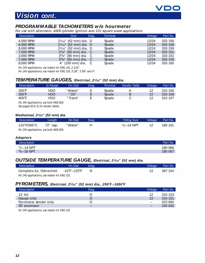
Vision cont.Vision cont.
PROGRAMMABLE TACHOMETERS w/o hourmeterFor use with alternator, 4/6/8 cylinder ignition and 12V square wave applications.
4,000 RPM 21/16" (52 mm) dia. D Spade 12/24 333 1566,000 RPM 21/16" (52 mm) dia. D Spade 12/24 333 1588,000 RPM 21/16" (52 mm) dia. D Spade 12/24 333 1597,000 RPM 31/8" (80 mm) dia. C Spade 12/24 333 1513,000 RPM 33/8" (85 mm) dia. C Spade 12/24 333 1527,000 RPM 33/8" (85 mm) dia. C Spade 12/24 333 1558,000 RPM 4" (100 mm) dia. C Spade 12/24 333 160For 24V applications, use resistor kit #391 101, 2 1/16".For 24V applications, use resistor kit #391 103, 3 1/8", 3 3/8" and 4".
TEMPERATURE GAUGES, Electrical, 21/16" (52 mm) dia.
250˚F VDO ”Water“ E Spade A 12 310 105300˚F VDO ”Oil“ E Spade B 12 310 106400˚F VDO ”Trans“ E Spade C 12 310 107For 24V applications, use bulb #600 826.See pages 30 & 31 for sender tables.
Mechanical, 21/16" (52 mm) dia.
110°F/265°C 72" cap. ”Water“ H 1/2–14 NPT 12 180 101For 24V applications, use bulb #600 826.
Adapters
1/2–14 NPT 180 0663/8 –18 NPT 180 067
OUTSIDE TEMPERATURE GAUGE, Electrical, 21/16" (52 mm) dia.
Complete kit, Fahrenheit -10˚F – 120˚F N 12 397 154For 24V applications, use resistor kit #391 101.
PYROMETERS, Electrical, 21/16" (52 mm) dia., 250˚F –1650˚F
12' Kit O 12 310 153Gauge only O 12 310 151Pyrometer sender only O – 323 89230' extension – – 240 092For 24V applications, use resistor kit #391 101.
Description Dwg. Voltage Part No.
Description On Dial Dwg. Voltage Part No.
Description Part No.
Description Length On Dial Dwg. Fitting Size Voltage Part No.
Description Ω Range On Dial Dwg. Terminal Sender Table Voltage Part No.
Description Size Dwg. Terminal Voltage Part No.
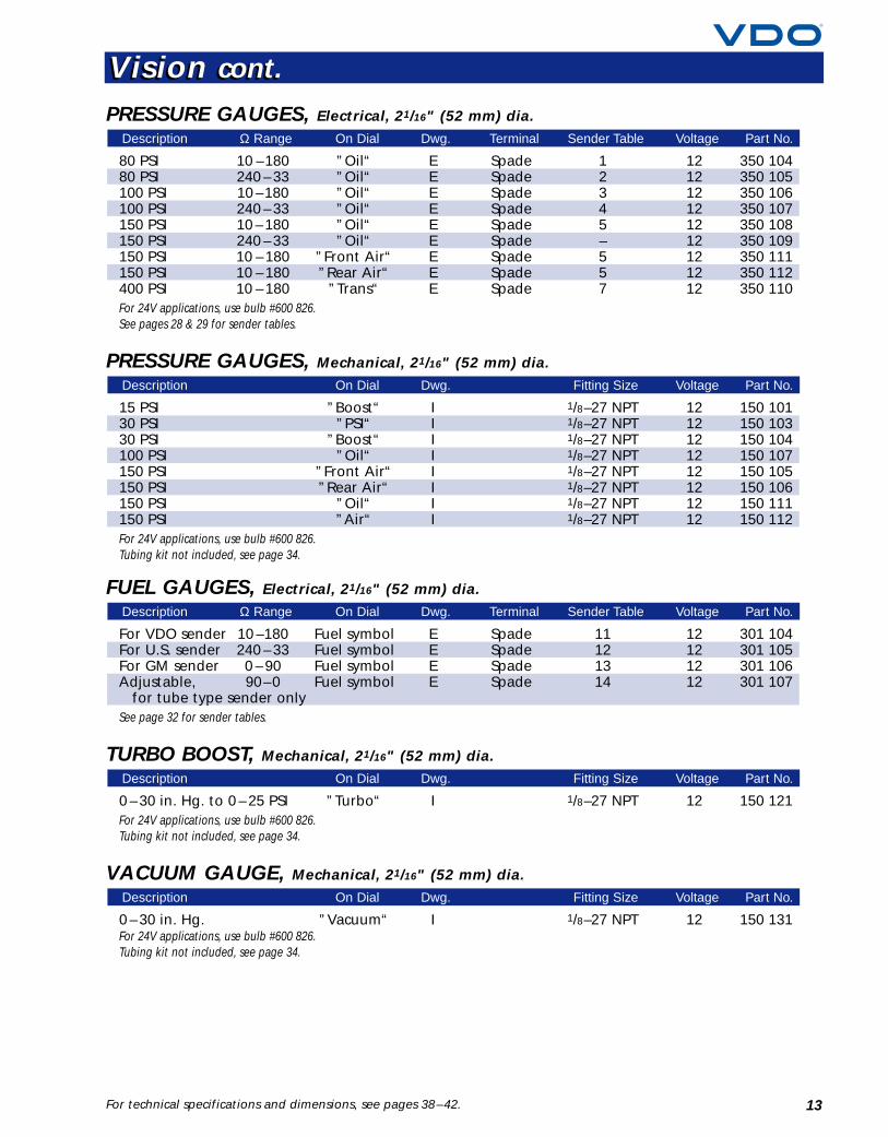
PRESSURE GAUGES, Electrical, 21/16" (52 mm) dia.
80 PSI 10 –180 ”Oil“ E Spade 1 12 350 10480 PSI 240 – 33 ”Oil“ E Spade 2 12 350 105100 PSI 10 –180 ”Oil“ E Spade 3 12 350 106100 PSI 240 – 33 ”Oil“ E Spade 4 12 350 107150 PSI 10 – 180 ”Oil“ E Spade 5 12 350 108150 PSI 240 – 33 ”Oil“ E Spade – 12 350 109150 PSI 10 – 180 ”Front Air“ E Spade 5 12 350 111150 PSI 10 – 180 ”Rear Air“ E Spade 5 12 350 112400 PSI 10 – 180 ”Trans“ E Spade 7 12 350 110For 24V applications, use bulb #600 826.See pages 28 & 29 for sender tables.
PRESSURE GAUGES, Mechanical, 21/16" (52 mm) dia.
15 PSI ”Boost“ I 1/8–27 NPT 12 150 10130 PSI ”PSI“ I 1/8–27 NPT 12 150 10330 PSI ”Boost“ I 1/8–27 NPT 12 150 104100 PSI ”Oil“ I 1/8–27 NPT 12 150 107150 PSI ”Front Air“ I 1/8–27 NPT 12 150 105150 PSI ”Rear Air“ I 1/8–27 NPT 12 150 106150 PSI ”Oil“ I 1/8–27 NPT 12 150 111150 PSI ”Air“ I 1/8–27 NPT 12 150 112For 24V applications, use bulb #600 826.Tubing kit not included, see page 34.
FUEL GAUGES, Electrical, 21/16" (52 mm) dia.
For VDO sender 10 –180 Fuel symbol E Spade 11 12 301 104For U.S. sender 240 – 33 Fuel symbol E Spade 12 12 301 105For GM sender 0 – 90 Fuel symbol E Spade 13 12 301 106Adjustable, 90–0 Fuel symbol E Spade 14 12 301 107
for tube type sender onlySee page 32 for sender tables.
TURBO BOOST, Mechanical, 21/16" (52 mm) dia.
0 – 30 in. Hg. to 0 – 25 PSI ”Turbo“ I 1/8–27 NPT 12 150 121For 24V applications, use bulb #600 826.Tubing kit not included, see page 34.
VACUUM GAUGE, Mechanical, 21/16" (52 mm) dia.
0 – 30 in. Hg. ”Vacuum“ I 1/8–27 NPT 12 150 131For 24V applications, use bulb #600 826.Tubing kit not included, see page 34.
Description On Dial Dwg. Fitting Size Voltage Part No.
Description On Dial Dwg. Fitting Size Voltage Part No.
Description Ω Range On Dial Dwg. Terminal Sender Table Voltage Part No.
Description On Dial Dwg. Fitting Size Voltage Part No.
Description Ω Range On Dial Dwg. Terminal Sender Table Voltage Part No.
13For technical specifications and dimensions, see pages 38–42.
Vision cont.Vision cont.
14
Vision cont.Vision cont.
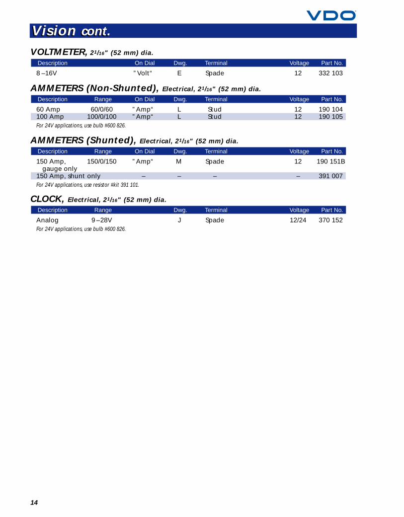
VOLTMETER, 21/16" (52 mm) dia.
8 –16V ”Volt“ E Spade 12 332 103
AMMETERS (Non-Shunted), Electrical, 21/16" (52 mm) dia.
60 Amp 60/0/60 ”Amp“ L Stud 12 190 104100 Amp 100/0/100 ”Amp“ L Stud 12 190 105For 24V applications, use bulb #600 826.
AMMETERS (Shunted), Electrical, 21/16" (52 mm) dia.
150 Amp, 150/0/150 ”Amp“ M Spade 12 190 151Bgauge only
150 Amp, shunt only – – – – 391 007For 24V applications, use resistor #kit 391 101.
CLOCK, Electrical, 21/16" (52 mm) dia.
Analog 9 –28V J Spade 12/24 370 152For 24V applications, use bulb #600 826.
Description Range Dwg. Terminal Voltage Part No.
Description Range On Dial Dwg. Terminal Voltage Part No.
Description Range On Dial Dwg. Terminal Voltage Part No.
Description On Dial Dwg. Terminal Voltage Part No.
VDO Series 1 instruments feature standard scales with step-type, chrome-plated brass bezels. Series 1 instruments utilize edge-lit dials andfeature easy-to-read white numerals and pointerson black faces. All housings are constructed of
zinc-plated steel and have U-bracket mountingand stud-type connections except where noted inthe technical specifications and dimensions sectionof this catalog.
15For technical specifications and dimensions, see pages 38–42.
PROGRAMMABLE SPEEDOMETERS w/resettable LCD tripodometerSeries 1 speedometers feature a unique auto-calibration function, allowing for easy adjustmentthrough the LCD display. Odometer and tripodometer readings are clearly displayed in the LCDwindow, and the operator may toggle between these modes with the push of a button.
For use with hall-effect, inductive, OEM electronic output and generator senders.
120 MPH 33/8" (85 mm) dia. A Spade 12/24 437 353160 MPH 33/8" (85 mm) dia. A Spade 12/24 437 354For 24V applications, use bulb #600 826 (2x).
MECHANICAL SPEEDOMETER w/o tripodometer, 5/8 –18 thread, 1.0 ratio
120 MPH / 200 KMH 33/8" (85 mm) dia. – – 12 120 302
PROGRAMMABLE TACHOMETER w/LCD hourmeterFor use with all current electronic control unit (DDEC, etc.), inductive, alternator, standard ignition,electronic ignition and hall-effect applications. Engine hours are displayed in the LCD window.
4,000 RPM 33/8" (85 mm) dia. B Spade 12/24 333 363For 24V applications, use bulb #600 826 (2x).
PROGRAMMABLE TACHOMETERS w/o hourmeterFor use with alternator, 4/6/8 cylinder ignition and 12V square wave applications.
4,000 RPM 33/8" (85 mm) dia. C Spade 12 333 3537,000 RPM 33/8" (85 mm) dia. C Spade 12 333 355For 24V applications, use resistor kit #391 103.
Description Size Dwg. Terminal Voltage Part No.
Description Size Dwg. Terminal Voltage Part No.
Description Size Dwg. Terminal Voltage Part No.
Description Size Dwg. Terminal Voltage Part No.
Series 1Series 1
16
Series 1 cont.Series 1 cont.
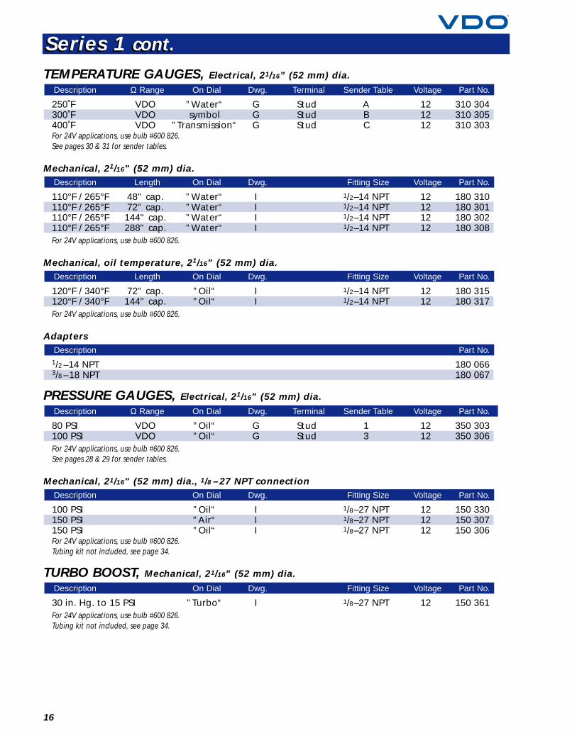
TEMPERATURE GAUGES, Electrical, 21/16” (52 mm) dia.
250˚F VDO ”Water“ G Stud A 12 310 304300˚F VDO symbol G Stud B 12 310 305400˚F VDO ”Transmission“ G Stud C 12 310 303For 24V applications, use bulb #600 826.See pages 30 & 31 for sender tables.
Mechanical, 21/16" (52 mm) dia.
110°F / 265°F 48" cap. ”Water“ I 1/2–14 NPT 12 180 310110°F / 265°F 72" cap. ”Water“ I 1/2–14 NPT 12 180 301110°F / 265°F 144" cap. ”Water“ I 1/2–14 NPT 12 180 302110°F / 265°F 288" cap. ”Water“ I 1/2–14 NPT 12 180 308For 24V applications, use bulb #600 826.
Mechanical, oil temperature, 21/16" (52 mm) dia.
120°F / 340°F 72" cap. ”Oil“ I 1/2–14 NPT 12 180 315120°F / 340°F 144" cap. ”Oil“ I 1/2–14 NPT 12 180 317For 24V applications, use bulb #600 826.
Adapters
1/2 –14 NPT 180 0663/8 –18 NPT 180 067
PRESSURE GAUGES, Electrical, 21/16" (52 mm) dia.
80 PSI VDO ”Oil“ G Stud 1 12 350 303100 PSI VDO ”Oil“ G Stud 3 12 350 306For 24V applications, use bulb #600 826.See pages 28 & 29 for sender tables.
Mechanical, 21/16" (52 mm) dia., 1/8 – 27 NPT connection
100 PSI ”Oil“ I 1/8–27 NPT 12 150 330150 PSI ”Air“ I 1/8–27 NPT 12 150 307150 PSI ”Oil“ I 1/8–27 NPT 12 150 306For 24V applications, use bulb #600 826.Tubing kit not included, see page 34.
TURBO BOOST, Mechanical, 21/16" (52 mm) dia.
30 in. Hg. to 15 PSI ”Turbo“ I 1/8–27 NPT 12 150 361For 24V applications, use bulb #600 826.Tubing kit not included, see page 34.
Description On Dial Dwg. Fitting Size Voltage Part No.
Description On Dial Dwg. Fitting Size Voltage Part No.
Description Ω Range On Dial Dwg. Terminal Sender Table Voltage Part No.
Description Part No.
Description Length On Dial Dwg. Fitting Size Voltage Part No.
Description Length On Dial Dwg. Fitting Size Voltage Part No.
Description Ω Range On Dial Dwg. Terminal Sender Table Voltage Part No.
17For technical specifications and dimensions, see pages 38–42.
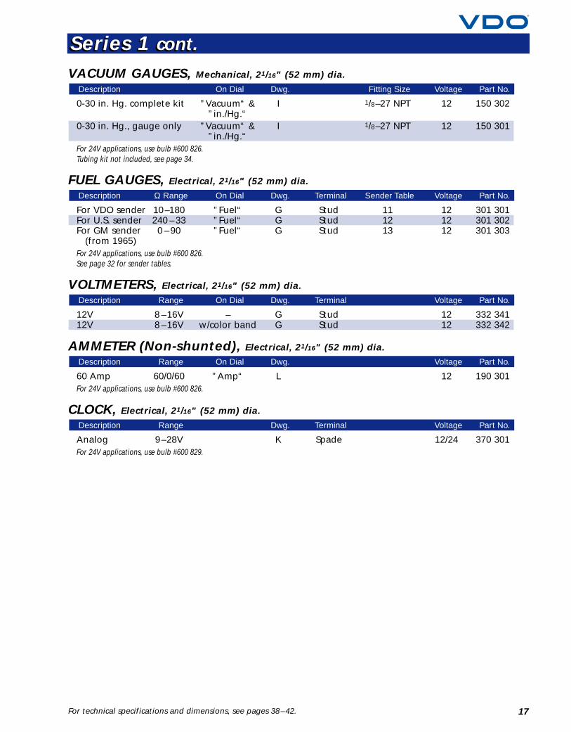
VACUUM GAUGES, Mechanical, 21/16" (52 mm) dia.
0-30 in. Hg. complete kit ”Vacuum“ & I 1/8–27 NPT 12 150 302”in./Hg.“
0-30 in. Hg., gauge only ”Vacuum“ & I 1/8–27 NPT 12 150 301”in./Hg.“
For 24V applications, use bulb #600 826.Tubing kit not included, see page 34.
FUEL GAUGES, Electrical, 21/16" (52 mm) dia.
For VDO sender 10–180 ”Fuel“ G Stud 11 12 301 301For U.S. sender 240 – 33 ”Fuel“ G Stud 12 12 301 302For GM sender 0 – 90 ”Fuel“ G Stud 13 12 301 303
(from 1965)For 24V applications, use bulb #600 826.See page 32 for sender tables.
VOLTMETERS, Electrical, 21/16" (52 mm) dia.
12V 8 –16V – G Stud 12 332 34112V 8 –16V w/color band G Stud 12 332 342
AMMETER (Non-shunted), Electrical, 21/16" (52 mm) dia.
60 Amp 60/0/60 ”Amp“ L 12 190 301For 24V applications, use bulb #600 826.
CLOCK, Electrical, 21/16" (52 mm) dia.
Analog 9–28V K Spade 12/24 370 301For 24V applications, use bulb #600 829.
Description Range Dwg. Terminal Voltage Part No.
Description Range On Dial Dwg. Voltage Part No.
Description Range On Dial Dwg. Terminal Voltage Part No.
Description Ω Range On Dial Dwg. Terminal Sender Table Voltage Part No.
Description On Dial Dwg. Fitting Size Voltage Part No.
Series 1 cont.Series 1 cont.
18
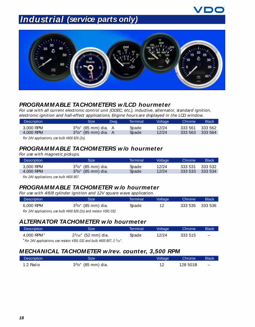
PROGRAMMABLE TACHOMETERS w/LCD hourmeterFor use with all current electronic control unit (DDEC, etc.), inductive, alternator, standard ignition,electronic ignition and hall-effect applications. Engine hours are displayed in the LCD window.
3,000 RPM 33/8" (85 mm) dia. A Spade 12/24 333 561 333 5624,000 RPM 33/8" (85 mm) dia. A Spade 12/24 333 563 333 564For 24V applications, use bulb #600 826 (2x).
PROGRAMMABLE TACHOMETERS w/o hourmeterFor use with magnetic pickups.
3,000 RPM 33/8" (85 mm) dia. Spade 12/24 333 531 333 5324,000 RPM 33/8" (85 mm) dia. Spade 12/24 333 533 333 534For 24V applications, use bulb #600 807.
PROGRAMMABLE TACHOMETER w/o hourmeterFor use with 4/6/8 cylinder ignition and 12V square wave application.
6,000 RPM 33/8" (85 mm) dia. Spade 12 333 535 333 536For 24V applications, use bulb #600 826 (2x) and resistor #391 032.
ALTERNATOR TACHOMETER w/o hourmeter
4,000 RPM* 21/16" (52 mm) dia. Spade 12/24 333 515 –*For 24V applications, use resistor #391 032 and bulb #600 807, 2 1/16".
MECHANICAL TACHOMETER w/rev. counter, 3,500 RPM
1:2 Ratio 33/8" (85 mm) dia. 12 128 501B –
Description Size Voltage Chrome Black
Description Size Terminal Voltage Chrome Black
Description Size Terminal Voltage Chrome Black
Description Size Terminal Voltage Chrome Black
Description Size Dwg. Terminal Voltage Chrome Black
Industrial (service parts only)Industrial (service parts only)
19For technical specifications and dimensions, see pages 38–42.
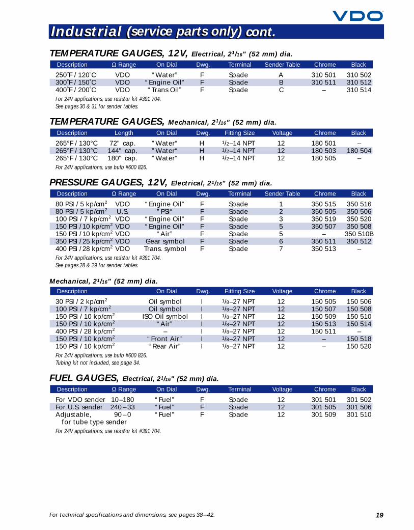
TEMPERATURE GAUGES, 12V, Electrical, 21/16" (52 mm) dia.
250˚F / 120˚C VDO “Water” F Spade A 310 501 310 502300˚F / 150˚C VDO “Engine Oil” F Spade B 310 511 310 512400˚F / 200˚C VDO “Trans Oil” F Spade C – 310 514For 24V applications, use resistor kit #391 704.See pages 30 & 31 for sender tables.
TEMPERATURE GAUGES, Mechanical, 21/16" (52 mm) dia.
265°F / 130°C 72" cap. ”Water“ H 1/2–14 NPT 12 180 501 –265°F / 130°C 144" cap. ”Water“ H 1/2–14 NPT 12 180 503 180 504265°F / 130°C 180" cap. ”Water“ H 1/2–14 NPT 12 180 505 –For 24V applications, use bulb #600 826.
PRESSURE GAUGES, 12V, Electrical, 21/16" (52 mm) dia.
80 PSI / 5 kp/cm2 VDO “Engine Oil” F Spade 1 350 515 350 51680 PSI / 5 kp/cm2 U.S. ”PSI“ F Spade 2 350 505 350 506100 PSI / 7 kp/cm2 VDO “Engine Oil” F Spade 3 350 519 350 520150 PSI / 10 kp/cm2 VDO “Engine Oil” F Spade 5 350 507 350 508150 PSI / 10 kp/cm2 VDO “Air” F Spade 5 – 350 510B350 PSI / 25 kp/cm2 VDO Gear symbol F Spade 6 350 511 350 512400 PSI / 28 kp/cm2 VDO Trans. symbol F Spade 7 350 513 –For 24V applications, use resistor kit #391 704.See pages 28 & 29 for sender tables.
Mechanical, 21/16" (52 mm) dia.
30 PSI / 2 kp/cm2 Oil symbol I 1/8–27 NPT 12 150 505 150 506100 PSI / 7 kp/cm2 Oil symbol I 1/8–27 NPT 12 150 507 150 508150 PSI / 10 kp/cm2 ISO Oil symbol I 1/8–27 NPT 12 150 509 150 510150 PSI / 10 kp/cm2 “Air” I 1/8–27 NPT 12 150 513 150 514400 PSI / 28 kp/cm2 – I 1/8–27 NPT 12 150 511 –150 PSI / 10 kp/cm2 “Front Air” I 1/8–27 NPT 12 – 150 518150 PSI / 10 kp/cm2 “Rear Air” I 1/8–27 NPT 12 – 150 520For 24V applications, use bulb #600 826.Tubing kit not included, see page 34.
FUEL GAUGES, Electrical, 21/16" (52 mm) dia.
For VDO sender 10–180 “Fuel” F Spade 12 301 501 301 502For U.S. sender 240 – 33 “Fuel” F Spade 12 301 505 301 506Adjustable, 90 – 0 “Fuel” F Spade 12 301 509 301 510
for tube type senderFor 24V applications, use resistor kit #391 704.
Description Ω Range On Dial Dwg. Terminal Voltage Chrome Black
Description On Dial Dwg. Fitting Size Voltage Chrome Black
Description Ω Range On Dial Dwg. Terminal Sender Table Chrome Black
Description Length On Dial Dwg. Fitting Size Voltage Chrome Black
Description Ω Range On Dial Dwg. Terminal Sender Table Chrome Black
Industrial (service parts only) cont.Industrial (service parts only) cont.

20
VOLTMETERS, Electrical, 21/16" (52 mm) dia.
12V 8 –16V F Spade 12 332 501 332 50224V 18 – 32V F Spade 24 332 503 332 504
AMMETER (Non-shunted), Electrical, 21/16" (52 mm) dia.
60 Amp 60/0/60 ”Amp“ L Spade 12 190 501 190 502For 24V applications, use bulb #600 826.
AMMETERS (Shunted)
150 Amp, 150/0/150 ”Amp“ M Spade 12 190 953 –complete kit
150 Amp, – – – – – 391 003 –shunt only w/lead wire
200 Amp, 200/0/200 ”Amp“ M Spade 12 – 190 514gauge only
200 Amp, – – – – 391 009 –shunt only
For 24V applications, use bulb #600 826.
Description Range On Dial Dwg. Terminal Voltage Chrome Black
Description Range On Dial Dwg. Terminal Voltage Chrome Black
Description Range Dwg. Terminal Voltage Chrome Black
Industrial (service parts only) cont.Industrial (service parts only) cont.
21For technical specifications and dimensions, see pages 38–42.
DC HOURMETERS, Electrical, 21/16" (52 mm) dia.
Cockpit International*
Non-illuminated “Hours” J Spade 12/24 331 951Illuminated “Hours” K Spade 12/24 331 020
LCD Hourmeter, 21/16" (52 mm) dia.**
Non-illuminated “Hours” Spade 9–64 331 523
Industrial**
Illuminated “Engine Hours” K Spade 12/24 331 501 331 502Non-illuminated “Hours” K Spade 12/24 331 503 331 504Illuminated “Pump Hours” K Spade 12/24 331 517B –
Waterproof
Non-illuminated “Hours” Spade 12/24 331 511 331 512
Three-hole flange
Non-illuminated, waterproof “Hours” Spade 12/24 331 514
Mini hourmeter
Rectangular, non-illuminated “Hours” Q Spade 12/24 331 534*For 24V applications, use bulb #600 826.**For 24V applications, use bulb #600 807.
Description On Dial Dwg. Terminal Voltage Part No.
Description On Dial Terminal Voltage Part No.
Description On Dial Terminal Voltage Chrome Black
Description On Dial Dwg. Terminal Voltage Chrome Black
Description On Dial Terminal Voltage Part No.
Description On Dial Dwg. Terminal Voltage Part No.
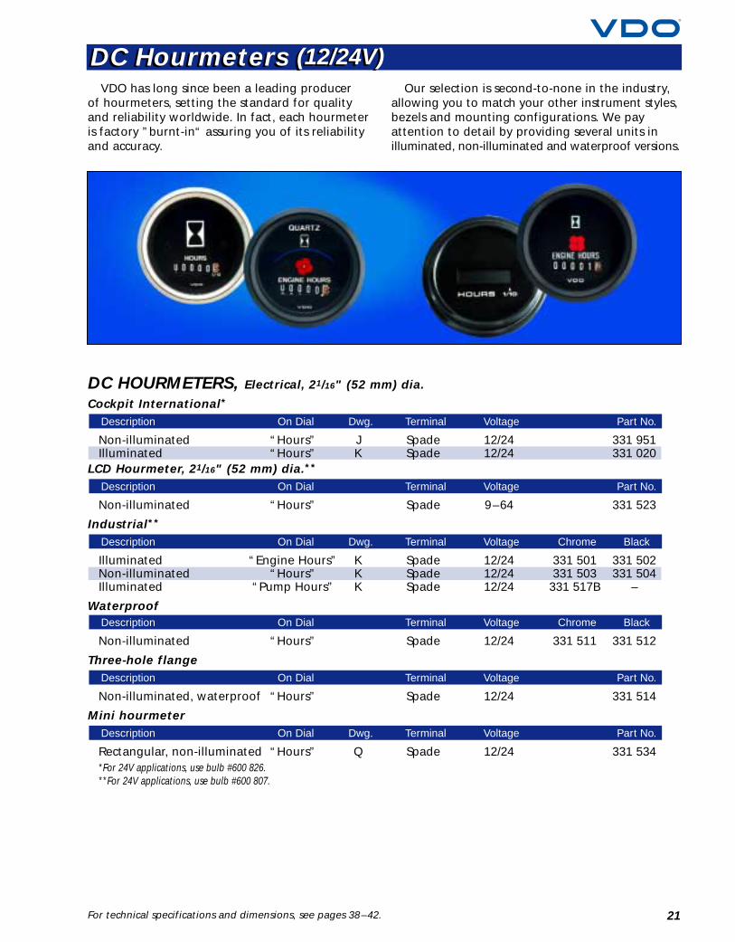
VDO has long since been a leading producerof hourmeters, setting the standard for qualityand reliability worldwide. In fact, each hourmeteris factory ”burnt-in“ assuring you of its reliabilityand accuracy.
Our selection is second-to-none in the industry,allowing you to match your other instrument styles,bezels and mounting configurations. We payattention to detail by providing several units inilluminated, non-illuminated and waterproof versions.
DC Hourmeters (12/24V)DC Hourmeters (12/24V)
22
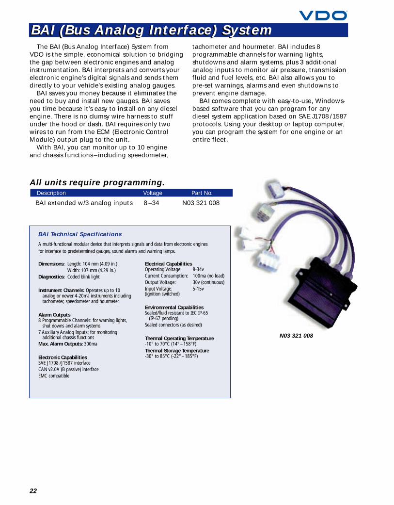
The BAI (Bus Analog Interface) System fromVDO is the simple, economical solution to bridgingthe gap between electronic engines and analoginstrumentation. BAI interprets and converts yourelectronic engine’s digital signals and sends themdirectly to your vehicle’s existing analog gauges.
BAI saves you money because it eliminates theneed to buy and install new gauges. BAI savesyou time because it’s easy to install on any dieselengine. There is no clumsy wire harness to stuffunder the hood or dash. BAI requires only twowires to run from the ECM (Electronic ControlModule) output plug to the unit.
With BAI, you can monitor up to 10 engineand chassis functions – including speedometer,
tachometer and hourmeter. BAI includes 8programmable channels for warning lights,shutdowns and alarm systems, plus 3 additionalanalog inputs to monitor air pressure, transmissionfluid and fuel levels, etc. BAI also allows you topre-set warnings, alarms and even shutdowns toprevent engine damage.
BAI comes complete with easy-to-use, Windows-based software that you can program for anydiesel system application based on SAE J1708 /1587protocols. Using your desktop or laptop computer,you can program the system for one engine or anentire fleet.
Dimensions: Length: 104 mm (4.09 in.)Width: 107 mm (4.29 in.)
Diagnostics: Coded blink light
Instrument Channels: Operates up to 10analog or newer 4-20ma instruments includingtachometer, speedometer and hourmeter.
Alarm Outputs8 Programmable Channels: for warning lights,
shut downs and alarm systems7 Auxiliary Analog Inputs: for monitoring
additional chassis functionsMax. Alarm Outputs: 300ma
Electronic CapabilitiesSAE J1708 /J1587 interfaceCAN v2.0A (B passive) interfaceEMC compatible
Electrical CapabilitiesOperating Voltage: 8-34vCurrent Consumption: 100ma (no load)Output Voltage: 30v (continuous)Input Voltage: 5-15v(ignition switched)
Environmental CapabilitiesSealed/fluid resistant to IEC IP-65
(IP-67 pending)Sealed connectors (as desired)
Thermal Operating Temperature-10° to 70°C (14° –158°F)Thermal Storage Temperature-30° to 85°C (-22° –185°F)
BAI Technical Specifications
A multi-functional modular device that interprets signals and data from electronic enginesfor interface to predetermined gauges, sound alarms and warning lamps.
All units require programming.
BAI extended w/3 analog inputs 8 –34 N03 321 008
Description Voltage Part No.
N03 321 008
BAI (Bus Analog Interface) SystemBAI (Bus Analog Interface) System
23For technical specifications and dimensions, see pages 38–42.
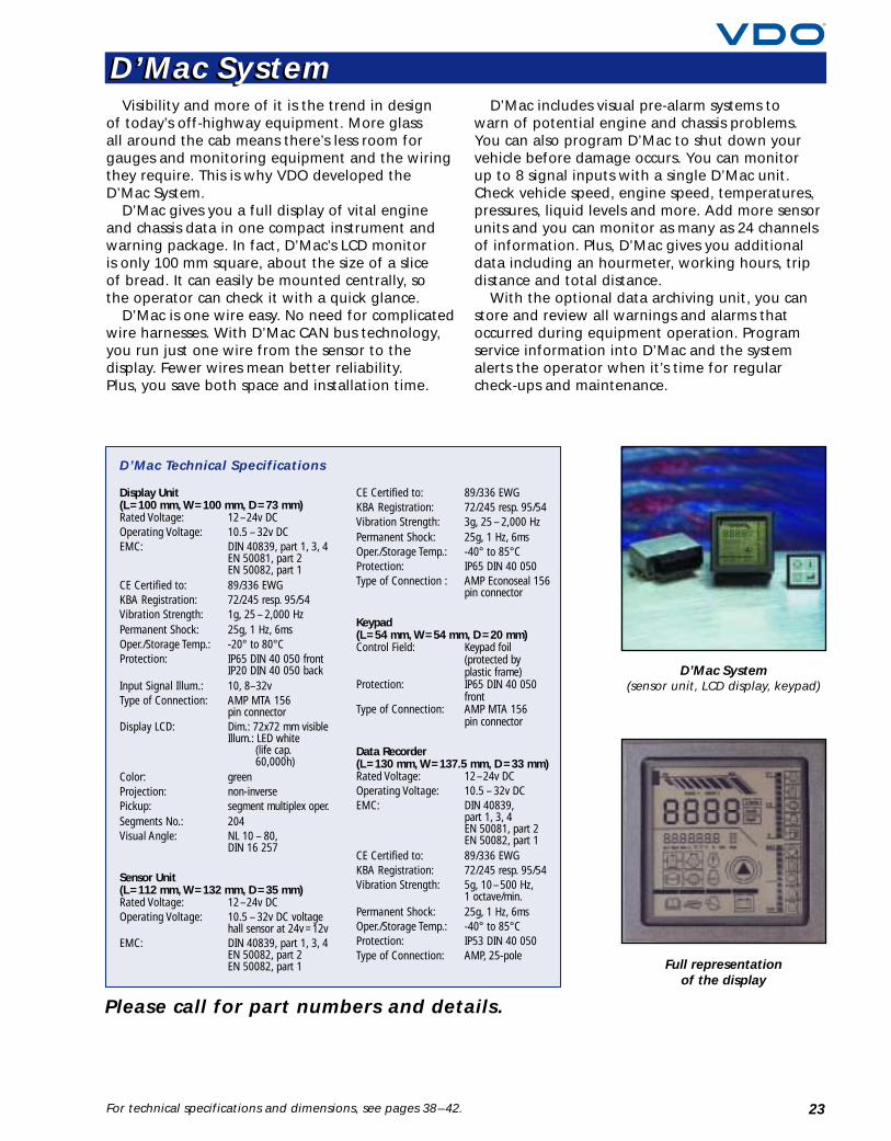
Visibility and more of it is the trend in designof today’s off-highway equipment. More glassall around the cab means there’s less room forgauges and monitoring equipment and the wiringthey require. This is why VDO developed theD’Mac System.
D’Mac gives you a full display of vital engineand chassis data in one compact instrument andwarning package. In fact, D’Mac’s LCD monitoris only 100 mm square, about the size of a sliceof bread. It can easily be mounted centrally, sothe operator can check it with a quick glance.
D’Mac is one wire easy. No need for complicatedwire harnesses. With D’Mac CAN bus technology,you run just one wire from the sensor to thedisplay. Fewer wires mean better reliability.Plus, you save both space and installation time.
D’Mac includes visual pre-alarm systems towarn of potential engine and chassis problems.You can also program D’Mac to shut down yourvehicle before damage occurs. You can monitorup to 8 signal inputs with a single D’Mac unit.Check vehicle speed, engine speed, temperatures,pressures, liquid levels and more. Add more sensorunits and you can monitor as many as 24 channelsof information. Plus, D’Mac gives you additionaldata including an hourmeter, working hours, tripdistance and total distance.
With the optional data archiving unit, you canstore and review all warnings and alarms thatoccurred during equipment operation. Programservice information into D’Mac and the systemalerts the operator when it’s time for regularcheck-ups and maintenance.
D’Mac System(sensor unit, LCD display, keypad)
Display Unit(L =100 mm, W =100 mm, D =73 mm)Rated Voltage: 12–24v DCOperating Voltage: 10.5 – 32v DCEMC: DIN 40839, part 1, 3, 4
EN 50081, part 2EN 50082, part 1
CE Certified to: 89/336 EWGKBA Registration: 72/245 resp. 95/54Vibration Strength: 1g, 25 – 2,000 HzPermanent Shock: 25g, 1 Hz, 6msOper./Storage Temp.: -20° to 80°CProtection: IP65 DIN 40 050 front
IP20 DIN 40 050 backInput Signal Illum.: 10, 8–32vType of Connection: AMP MTA 156
pin connectorDisplay LCD: Dim.: 72x72 mm visible
Illum.: LED white(life cap.60,000h)
Color: greenProjection: non-inversePickup: segment multiplex oper.Segments No.: 204Visual Angle: NL 10 – 80,
DIN 16 257
Sensor Unit(L =112 mm, W =132 mm, D =35 mm)Rated Voltage: 12–24v DCOperating Voltage: 10.5 – 32v DC voltage
hall sensor at 24v =12vEMC: DIN 40839, part 1, 3, 4
EN 50082, part 2EN 50082, part 1
CE Certified to: 89/336 EWGKBA Registration: 72/245 resp. 95/54Vibration Strength: 3g, 25 – 2,000 HzPermanent Shock: 25g, 1 Hz, 6msOper./Storage Temp.: -40° to 85°CProtection: IP65 DIN 40 050Type of Connection : AMP Econoseal 156
pin connector
Keypad(L =54 mm, W =54 mm, D =20 mm)Control Field: Keypad foil
(protected byplastic frame)
Protection: IP65 DIN 40 050front
Type of Connection: AMP MTA 156pin connector
Data Recorder(L =130 mm, W =137.5 mm, D =33 mm)Rated Voltage: 12–24v DCOperating Voltage: 10.5 – 32v DCEMC: DIN 40839,
part 1, 3, 4EN 50081, part 2EN 50082, part 1
CE Certified to: 89/336 EWGKBA Registration: 72/245 resp. 95/54Vibration Strength: 5g, 10–500 Hz,
1 octave/min.Permanent Shock: 25g, 1 Hz, 6msOper./Storage Temp.: -40° to 85°CProtection: IP53 DIN 40 050Type of Connection: AMP, 25-pole
D’Mac Technical Specifications
Full representationof the display
Please call for part numbers and details.
D’Mac SystemD’Mac System
24
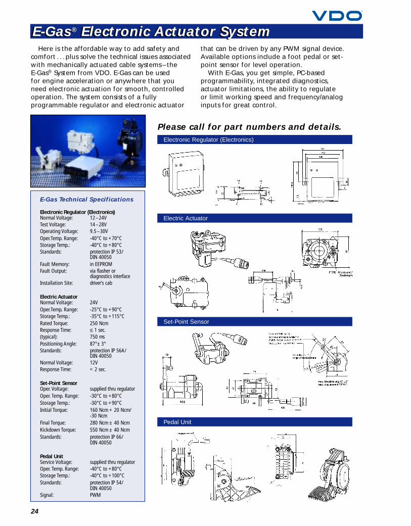
Here is the affordable way to add safety andcomfort . . . plus solve the technical issues associatedwith mechanically actuated cable systems – theE-Gas® System from VDO. E-Gas can be usedfor engine acceleration or anywhere that youneed electronic actuation for smooth, controlledoperation. The system consists of a fullyprogrammable regulator and electronic actuator
that can be driven by any PWM signal device.Available options include a foot pedal or set-point sensor for level operation.
With E-Gas, you get simple, PC-basedprogrammability, integrated diagnostics,actuator limitations, the ability to regulateor limit working speed and frequency/analoginputs for great control.
Electronic Regulator (Electronics)Normal Voltage: 12–24VTest Voltage: 14–28VOperating Voltage: 9.5–30VOper.Temp. Range: -40°C to +70°CStorage Temp.: -40°C to +80°CStandards: protection IP 53/
DIN 40050Fault Memory: in EEPROMFault Output: via flasher or
diagnostics interfaceInstallation Site: driver’s cab
Electric ActuatorNormal Voltage: 24VOper.Temp. Range: -25°C to +90°CStorage Temp.: -35°C to +115°CRated Torque: 250 NcmResponse Time: ≤ 1 sec.(typical): 750 msPositioning Angle: 87°± 3°Standards: protection IP 56A/
DIN 40050Normal Voltage: 12VResponse Time: < 2 sec.
Set-Point SensorOper. Voltage: supplied thru regulatorOper. Temp. Range: -30°C to +80°CStorage Temp.: -30°C to +90°CInitial Torque: 160 Ncm + 20 Ncm/
-30 NcmFinal Torque: 280 Ncm ± 40 NcmKickdown Torque: 550 Ncm ± 40 NcmStandards: protection IP 66/
DIN 40050
Pedal UnitService Voltage: supplied thru regulatorOper. Temp. Range: -40°C to +80°CStorage Temp.: -40°C to +100°CStandards: protection IP 54/
DIN 40050Signal: PWM
E-Gas Technical Specifications
Electronic Regulator (Electronics)
Electric Actuator
Set-Point Sensor
Pedal Unit
Please call for part numbers and details.
E-Gas® Electronic Actuator SystemE-Gas® Electronic Actuator System
25
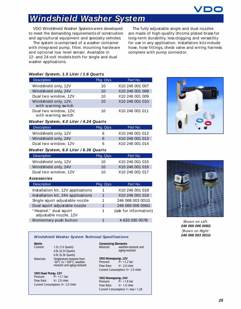
VDO Windshield Washer Systems were developedto meet the demanding requirements of constructionand agricultural equipment and specialty vehicles.
The system is comprised of a washer containerwith integrated pump, filter, mounting hardwareand optional low level sensor. Available in12- and 24-volt models both for single and dualwasher applications.
The fully adjustable single and dual nozzlesare made of high-quality chrome plated brass forlong-term durability, less clogging and versatilityfor use in any application. Installation kits includehose, hose fittings, check valve and wiring harnesscomplete with pump connector.
Washer System, 1.5 Liter / 1.6 Quarts
Windshield only, 12V 10 X10 246 001 007Windshield only, 24V 10 X10 246 001 008Dual two window, 12V 10 X10 246 001 009Windshield only, 12V, 10 X10 246 001 010
with warning switchDual two window, 12V, 10 X10 246 001 011
with warning switch
Washer System, 4.0 Liter / 4.24 Quarts
Windshield only, 12V 6 X10 246 001 012Windshield only, 24V 6 X10 246 001 013Dual two window, 12V 6 X10 246 001 014
Washer System, 6.0 Liter / 6.36 Quarts
Windshield only, 12V 10 X10 246 001 015Windshield only, 24V 10 X10 246 001 016Dual two window, 12V 10 X10 246 001 017
Accessories
Installation kit, 12V applications 1 X10 246 001 018Installation kit, 24V applications 1 X10 246 001 019Single squirt adjustable nozzle 1 246 068 003 001GDual squirt adjustable nozzle 1 246 069 006 006G“Heated,” dual squirt 1 (ask for information)
adjustable nozzle, 12VMomentary push button 1 4 633 030 007B
Description Pkg. Qtys. Part No.
Description Pkg. Qtys. Part No.
Description Pkg. Qtys. Part No.
Description Pkg. Qtys. Part No.
BottleContent: 1.5L (1.6 Quarts)
4.0L (4.24 Quarts)6.0L (6.36 Quarts)
Materials: Temperature-resistant from-30°C to +100°C, weather-resistant and aging-resistant
VDO Dual Pump, 12VPressure: P= +2.1 barFlow Rate: V= 2.0 i/minCurrent Consumption: V= 2.0 i/min
Connecting ElementsMaterial: weather-resistant and
aging-resistant
VDO Monopump, 12VPressure: P= +2.2 barFlow Rate: V= 2.0 i/minCurrent Consumption: V= 2.0 i/min
VDO Monopump, 24VPressure: P= +1.8 barFlow Rate: V= 1.0 i/minCurrent Consumption: l= max =1.2A
Windshield Washer System Technical Specifications
Shown on Left:246 069 006 006GShown on Right:246 068 003 001G
Windshield Washer SystemWindshield Washer System
26
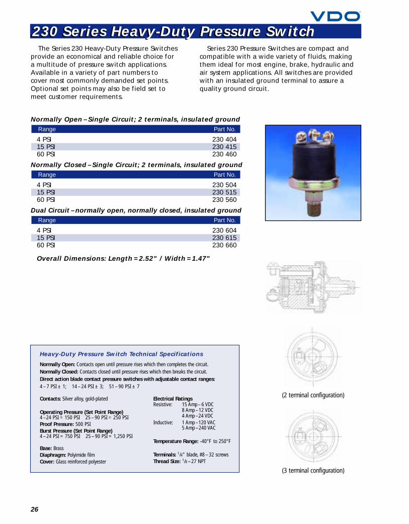
The Series 230 Heavy-Duty Pressure Switchesprovide an economical and reliable choice fora multitude of pressure switch applications.Available in a variety of part numbers tocover most commonly demanded set points.Optional set points may also be field set tomeet customer requirements.
Series 230 Pressure Switches are compact andcompatible with a wide variety of fluids, makingthem ideal for most engine, brake, hydraulic andair system applications. All switches are providedwith an insulated ground terminal to assure aquality ground circuit.
Normally Open – Single Circuit; 2 terminals, insulated ground
4 PSI 230 40415 PSI 230 41560 PSI 230 460
Normally Closed – Single Circuit; 2 terminals, insulated ground
4 PSI 230 50415 PSI 230 51560 PSI 230 560
Dual Circuit – normally open, normally closed, insulated ground
4 PSI 230 60415 PSI 230 61560 PSI 230 660
Overall Dimensions: Length = 2.52" / Width = 1.47"
Range Part No.
Range Part No.
Range Part No.
Contacts: Silver alloy, gold-plated
Operating Pressure (Set Point Range)4 –24 PSI = 150 PSI 25 – 90 PSI = 250 PSIProof Pressure: 500 PSIBurst Pressure (Set Point Range)4 –24 PSI = 750 PSI 25 – 90 PSI = 1,250 PSI
Base: BrassDiaphragm: Polyimide film Cover: Glass reinforced polyester
Electrical RatingsResistive: 15 Amp – 6 VDC
8 Amp –12 VDC4 Amp –24 VDC
Inductive: 1 Amp –120 VAC5 Amp –240 VAC
Temperature Range: -40°F to 250°F
Terminals: 1/4" blade, #8 – 32 screwsThread Size: 1/8 –27 NPT
Heavy-Duty Pressure Switch Technical Specifications
Normally Open: Contacts open until pressure rises which then completes the circuit.Normally Closed: Contacts closed until pressure rises which then breaks the circuit.Direct action blade contact pressure switches with adjustable contact ranges:4 – 7 PSI ± 1; 14 – 24 PSI ± 3; 51 – 90 PSI ± 7
(2 terminal configuration)
(3 terminal configuration)
230 Series Heavy-Duty Pressure Switch230 Series Heavy-Duty Pressure Switch
illus. E
27
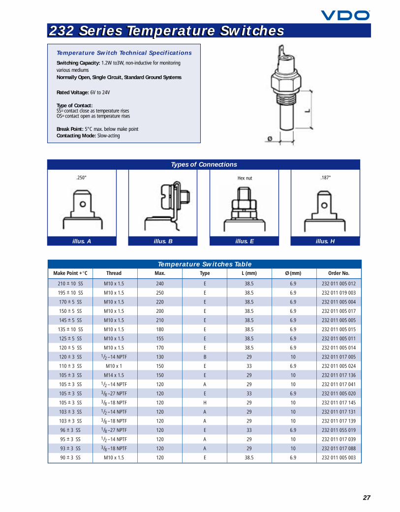
232 Series Temperature Switches232 Series Temperature Switches
illus. A illus. B illus. H
Types of Connections
.250" Hex nut .187"
Rated Voltage: 6V to 24V
Type of Contact:SS=contact close as temperature risesOS=contact open as temperature rises
Break Point: 5°C max. below make pointContacting Mode: Slow-acting
Temperature Switch Technical Specifications
Switching Capacity: 1.2W to3W, non-inductive for monitoringvarious mediumsNormally Open, Single Circuit, Standard Ground Systems
Make Point +°C Thread Max. Type Order No.L (mm) Ø (mm)
Temperature Switches Table
210 ± 10 SS
195 ± 10 SS
170 ± 5 SS
150 ± 5 SS
145 ± 5 SS
135 ± 10 SS
125 ± 5 SS
120 ± 5 SS
120 ± 3 SS
110 ± 3 SS
105 ± 3 SS
105 ± 3 SS
105 ± 3 SS
105 ± 3 SS
103 ± 3 SS
103 ± 3 SS
96 ± 3 SS
95 ± 3 SS
93 ± 3 SS
90 ± 3 SS
M10 x 1.5
M10 x 1.5
M10 x 1.5
M10 x 1.5
M10 x 1.5
M10 x 1.5
M10 x 1.5
M10 x 1.5
1/2 –14 NPTF
M10 x 1
M14 x 1.5
1/2 –14 NPTF
3/8 –27 NPTF
3/8 –18 NPTF
1/2 –14 NPTF
3/8 –18 NPTF
1/8 –27 NPTF
1/2 –14 NPTF
3/8 –18 NPTF
M10 x 1.5
240
250
220
200
210
180
155
170
130
150
150
120
120
120
120
120
120
120
120
120
E
E
E
E
E
E
E
E
B
E
E
A
E
H
A
A
E
A
A
E
232 011 005 012
232 011 019 003
232 011 005 004
232 011 005 017
232 011 005 005
232 011 005 015
232 011 005 011
232 011 005 014
232 011 017 005
232 011 005 024
232 011 017 136
232 011 017 041
232 011 005 020
232 011 017 145
232 011 017 131
232 011 017 139
232 011 055 019
232 011 017 039
232 011 017 088
232 011 005 003
38.5
38.5
38.5
38.5
38.5
38.5
38.5
38.5
29
33
29
29
33
29
29
29
33
29
29
38.5
6.9
6.9
6.9
6.9
6.9
6.9
6.9
6.9
10
6.9
10
10
6.9
10
10
10
6.9
10
10
6.9
Thread # Stamped on Sender
Table 3: 100 PSI / 7 bar (10 –180 OHM)
1/8 –27 NPT – 360 086 – – – 655
Std. Ground(illus. 1)
Warning Contact(illus. 3)
Floating Ground(illus. 2)
Dual Station(illus. 1)
Dual StationFloating Ground
(illus. 2)
28
illus. 1 illus. 2 illus. 3
Standard Ground:sender case to
common ground
Floating Ground:isolated terminal to
common ground; andDual Station Floating
Ground
Standard Groundwith Warning Contact
Thread Std. Ground(illus. 1)
Warning Contact(illus. 3)
Floating Ground(illus. 2)
Dual Station(illus. 1)
Dual StationFloating Ground
(illus. 2)# Stampedon Sender
WasherRequired
Table 1: 80 PSI / 5 bar (10 –180 OHM)
1/8 –27 NPT
1/8 –27 NPT
1/8 –27 NPT
1/8 –27 NPT
1/8 –27 NPT
1/4 –18 NPT
1/4 –18 NPT
1/4 –18 NPT
1/8 –28 BSP
M10 x 1K
M10 x 1K
M10 x 1K
M12 x 1.5
M12 x 1.5
M14 x 1.5
M15 x 1.5
–
–
–
7.0 PSI
–
–
8.0 PSI
–
–
–
7.0 PSI
10.0 PSI
–
8.5 PSI
–
7.1 PSI
360 003
–
–
360 009
–
360 005
360 019
–
360 080
360 001
360 006
360 034
360 002
360 007
360 027
360 028
–
360 410
–
–
–
–
–
360 441B
–
–
–
–
–
–
–
–
–
–
–
–
362 033
–
–
–
–
–
–
–
–
–
–
–
–
–
362 001
–
–
–
–
–
–
–
–
–
–
–
–
–
29/4
32/1
1/1
30/23
3/1
29/8
30/20
32/16
29/61
29/1
30/2
30/4
29/85
30/6
29/26
30/28
–
–
–
–
–
–
–
–
–
–
–
–
X
X
X
X
Thread Std. Ground(illus. 1)
Warning Contact(illus. 3)
Floating Ground(illus. 2)
Dual Station(illus. 1)
Dual StationFloating Ground
(illus. 2)# Stamped on Sender
Table 2: 80 PSI / 5 bar (240 –33 OHM)
1/8 –27 NPT – 360 801 – – – AT 84200
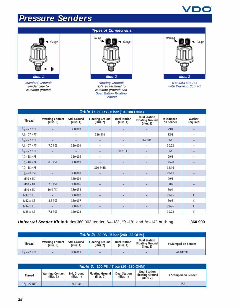
Types of Connections
Universal Sender Kit includes 360 003 sender, 1/4–18", 3/8–18" and 1/2–14" bushing. 360 900
GaugeGround Warning
GaugeGauge
Pressure SendersPressure Senders
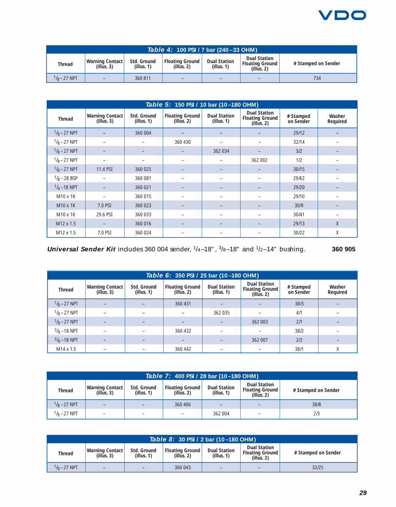
29
Thread # Stamped on Sender
Table 4: 100 PSI / 7 bar (240 –33 OHM)
1/8 –27 NPT – 360 811 – – – 734
Std. Ground(illus. 1)
Warning Contact(illus. 3)
Floating Ground(illus. 2)
Dual Station(illus. 1)
Dual StationFloating Ground
(illus. 2)
Thread # Stampedon Sender
WasherRequired
Table 5: 150 PSI / 10 bar (10 –180 OHM)
1/8 –27 NPT
1/8 –27 NPT
1/8 –27 NPT
1/8 –27 NPT
1/8 –27 NPT
1/8 –28 BSP
1/4 –18 NPT
M10 x 1K
M10 x 1K
M10 x 1K
M12 x 1.5
M12 x 1.5
–
–
–
–
11.4 PSI
–
–
–
7.0 PSI
29.6 PSI
–
7.0 PSI
360 004
–
–
–
360 025
360 081
360 021
360 015
360 023
360 033
360 016
360 024
–
360 430
–
–
–
–
–
–
–
–
–
–
–
–
362 034
–
–
–
–
–
–
–
–
–
–
–
–
362 002
–
–
–
–
–
–
–
–
29/12
32/14
3/2
1/2
30/15
29/62
29/20
29/10
30/9
30/41
29/13
30/22
–
–
–
–
–
–
–
–
–
–
X
X
Std. Ground(illus. 1)
Warning Contact(illus. 3)
Floating Ground(illus. 2)
Dual Station(illus. 1)
Dual StationFloating Ground
(illus. 2)
Thread # Stampedon Sender
WasherRequired
Table 6: 350 PSI / 25 bar (10 –180 OHM)
1/8 –27 NPT
1/8 –27 NPT
1/8 –27 NPT
3/8 –18 NPT
3/8 –18 NPT
M14 x 1.5
–
–
–
–
–
–
–
–
–
–
–
–
360 431
–
–
360 432
–
360 442
–
362 035
–
–
–
–
–
–
362 003
–
362 007
–
38/3
4/1
2/1
38/2
2/2
38/1
–
–
–
–
–
X
Std. Ground(illus. 1)
Warning Contact(illus. 3)
Floating Ground(illus. 2)
Dual Station(illus. 1)
Dual StationFloating Ground
(illus. 2)
Thread # Stamped on Sender
Table 7: 400 PSI / 28 bar (10 –180 OHM)
1/8 –27 NPT
1/8 –27 NPT
–
–
–
–
360 406
–
–
362 004
–
–
38/8
2/3
Std. Ground(illus. 1)
Warning Contact(illus. 3)
Floating Ground(illus. 2)
Dual Station(illus. 1)
Dual StationFloating Ground
(illus. 2)
Thread # Stamped on Sender
Table 8: 30 PSI / 2 bar (10 –180 OHM)
1/8 –27 NPT – – 360 043 – – 32/25
Std. Ground(illus. 1)
Warning Contact(illus. 3)
Floating Ground(illus. 2)
Dual Station(illus. 1)
Dual StationFloating Ground
(illus. 2)
Universal Sender Kit includes 360 004 sender, 1/4–18", 3/8–18" and 1/2–14" bushing. 360 905
30
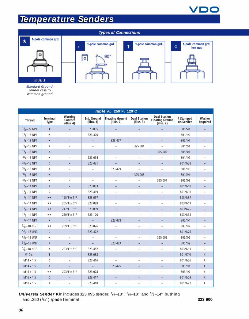
illus. 1
Standard Ground:sender case to
common ground
Thread Std. Ground(illus. 1)
TerminalType
Floating Ground(illus. 2)
Dual Station(illus. 3)
Dual StationFloating Ground
(illus. 2)
WarningContact(illus. 4)
# Stampedon Sender
WasherRequired
Table A: 250°F / 120°C
1/8 –27 NPT
1/4 –18 NPT
1/4 –18 NPT
1/4 –18 NPT
1/4 –18 NPT
3/8 –18 NPT
3/8 –18 NPT
3/8 –18 NPT
3/8 –18 NPT
3/8 –18 NPT
1/2 –14 NPT
1/2 –14 NPT
1/2 –14 NPT
1/2 –14 NPT
1/2 –14 NPT
1/2 –14 NPT
1/2 –14 NPT
5/8 –18 NF-3
5/8 –18 UNF
5/8 –18 UNF
5/8 –18 UNF
5/8 –18 NF-3
M10 x 1
M14 x 1.5
M14 x 1.5
M16 x 1.5
M16 x 1.5
M18 x 1.5
T
*****◊
****◊
*********
**◊
***T
◊
***◊
*
–
–
–
–
–
–
–
–
–
–
–
–
195°F ± 5°F
205°F ± 5°F
217°F ± 5°F
230°F ± 5°F
–
209°F ± 5°F
–
–
–
203°F ± 5°F
–
–
–
203°F ± 5°F
–
–
–
–
323 477
–
–
–
–
323 479
–
–
–
–
–
–
–
–
323 478
–
–
–
323 483
–
–
–
323 425
–
–
–
323 095
323 420
–
–
–
323 094
323 421
–
–
–
323 093
323 419
323 097
323 098
323 099
323 100
–
323 026
323 422
–
–
323 487
323 088
323 416
–
323 028
323 417
323 418
–
–
–
325 001
–
–
–
–
325 008
–
–
–
–
–
–
–
–
–
–
–
–
–
–
–
–
–
–
–
–
–
–
–
325 002
–
–
–
–
325 007
–
–
–
–
–
–
–
–
–
325 003
–
–
–
–
–
–
–
–
801/5/1
801/1/9
805/1/7
801/2/1
805/3/1
801/1/7
801/1/38
805/1/5
801/2/4
805/3/3
801/1/10
801/1/16
803/1/37
803/1/19
803/1/25
803/1/32
805/1/4
803/1/2
801/1/25
805/3/2
805/1/2
803/1/11
801/17/1
801/1/26
805/1/1
803/1/7
801/1/29
801/1/22
–
–
–
–
–
–
–
–
–
–
–
–
–
–
–
–
–
–
–
–
–
–
X
X
X
X
X
X
s T ◊ 1-pole common grd.hex nut
1-pole common grd. 1-pole common grd.*1-pole common grd.
Universal Sender Kit includes 323 095 sender, 1/4–18", 3/8–18" and 1/2–14" bushingand .250 (1/4") spade terminal 323 900
Types of Connections
Temperature SendersTemperature Senders

31For technical specifications and dimensions, see pages 38–42.
illus. 2 illus. 3 illus. 4
Floating Ground:isolated terminal to
common ground
Dual Station:2 gauges operationfrom single sender
Dual StationFloating Ground:
same as Dual Station;however, isolated
terminal to ground
Thread Std. Ground(illus. 1)
TerminalType
Floating Ground(illus. 2)
Dual Station(illus. 3)
Dual StationFloating Ground
(illus. 2)# Stampedon Sender
WasherRequired
Table B: 300°F / 150°C
1/8 –27 NPT
1/4 –18 NPT
1/4 –18 NPT
3/8 –18 NPT
1/2 –14 NPT
1/2 –14 NPT
5/8 –18 UNF
5/8 –18 UNF
M10 x 1
M12 x 1.5
M14 x 1.5
M16 x 1.5
M18 x 1.5
M22 x 1.5
T
◊
**◊
**◊
*T
T
s
s
s
s
–
–
–
–
–
250°F ± 5°F
–
–
–
–
–
–
–
–
–
–
323 485
–
–
–
–
323 431
–
–
–
–
–
–
323 057
323 058
–
323 059
323 060
323 120
323 061
–
323 423
323 092
323 055
323 056
323 064
323 066
–
–
–
–
–
–
–
–
–
–
–
–
–
–
–
–
–
–
–
–
–
–
–
–
–
–
–
–
801/9/1
801/4/17
805/3/2
801/4/15
801/4/6
803/2/15
801/4/9
805/3/3
801/9/3
801/10/3
801/12/2
801/12/1
801/12/3
801/12/4
–
–
–
–
–
–
–
–
X
X
X
X
X
X
WarningContact(illus. 4)
Thread Std. Ground(illus. 1)
TerminalType
Floating Ground(illus. 2)
Dual Station(illus. 3)
Dual StationFloating Ground
(illus. 2)
WarningContact(illus. 4)
# Stampedon Sender
WasherRequired
Table C: 400°F / 200°C
1/8 –27 NPT
1/8 –27 NPT
M10 x 1.5
M10 x 1
T
T
T
T
–
–
–
–
–
–
(Long probe, 5/8" long) Ford
(Short probe, 3/8" long) GM
323 050
323 086
323 091
323 090
–
–
–
–
801/13/1
801/18/1
801/3/1
801/3/2
–
–
X
X
* Straight .250" spadeterminal
◊ 4 mm screw stud
s 90° angle .250" spadespade terminal
T .250" ”posi lock”terminal
* 56 Series ”Packard”female terminal, unsealedw/terminal housing
** Gauge .250" spadeterminal; Warning.187" spade terminal
**G= .250" spade conn.W= .187" spade conn.*
1-pole common grd.Connection Key
Universal Sender Kit includes 323 057 sender, 1/4–18", 3/8–18" and 1/2–14" bushingand .250 (1/4") spade terminal 323 905
GaugeWarning
Types of Connections
32
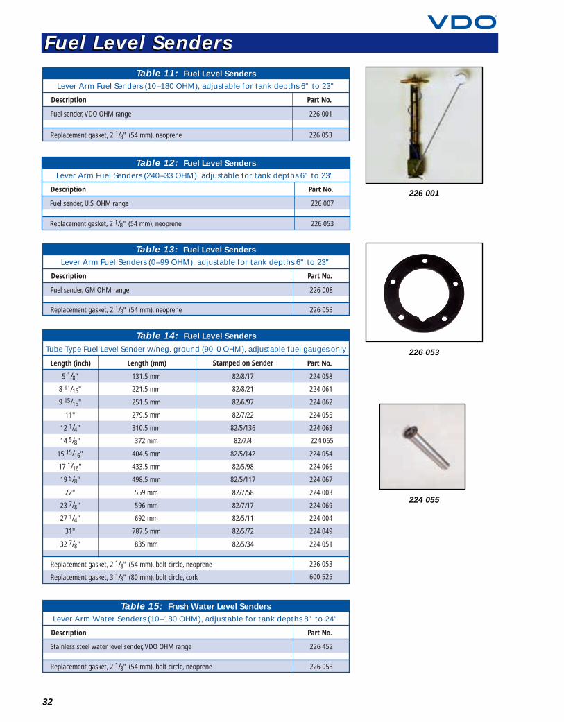
226 001
224 055
226 053
Description Part No.
Table 11: Fuel Level SendersLever Arm Fuel Senders (10–180 OHM), adjustable for tank depths 6" to 23"
Fuel sender, VDO OHM range
Replacement gasket, 2 1/8" (54 mm), neoprene
226 001
226 053
Description Part No.
Table 12: Fuel Level SendersLever Arm Fuel Senders (240–33 OHM), adjustable for tank depths 6" to 23"
Fuel sender, U.S. OHM range
Replacement gasket, 2 1/8" (54 mm), neoprene
226 007
226 053
Description Part No.
Table 13: Fuel Level SendersLever Arm Fuel Senders (0–99 OHM), adjustable for tank depths 6" to 23"
Fuel sender, GM OHM range
Replacement gasket, 2 1/8" (54 mm), neoprene
226 008
226 053
Length (inch) Part No.Length (mm) Stamped on Sender
Table 14: Fuel Level Senders
Tube Type Fuel Level Sender w/neg. ground (90–0 OHM), adjustable fuel gauges only
5 1/8"
8 11/16"
9 15/16"
11"
12 1/4"
14 5/8"
15 15/16"
17 1/16"
19 5/8"
22"
23 7/8"
27 1/4"
31"
32 7/8"
131.5 mm
221.5 mm
251.5 mm
279.5 mm
310.5 mm
372 mm
404.5 mm
433.5 mm
498.5 mm
559 mm
596 mm
692 mm
787.5 mm
835 mm
82/8/17
82/8/21
82/6/97
82/7/22
82/5/136
82/7/4
82/5/142
82/5/98
82/5/117
82/7/58
82/7/17
82/5/11
82/5/72
82/5/34
224 058
224 061
224 062
224 055
224 063
224 065
224 054
224 066
224 067
224 003
224 069
224 004
224 049
224 051
226 053
600 525
Replacement gasket, 2 1/8" (54 mm), bolt circle, neoprene
Replacement gasket, 3 1/8" (80 mm), bolt circle, cork
Description Part No.
Table 15: Fresh Water Level SendersLever Arm Water Senders (10–180 OHM), adjustable for tank depths 8" to 24"
Stainless steel water level sender, VDO OHM range
Replacement gasket, 2 1/8" (54 mm), bolt circle, neoprene
226 452
226 053
Fuel Level SendersFuel Level Senders
340 020
340 001
340 060
33
Generator SendersFor use with VDO speedometers and tachometers designatedas generator-type
Without odometer /revolution counter terminal
7/8 –18 thread 340 001M22 x 1.5 thread 340 002
Drive keys for generator senders listed above
.152" – tang 340 060
.187" – tang 340 061
.203" – tang 340 062
.104" – square 340 065
.200" – Perkins 340 064
Inductive / Magnetic Pick-Up SenderFor inductive and programmable speedometers and tachometers
2" long, 3/4 –16 thread 340 020
Hall-Effect For electronic, programmable speedometers, 7/8 –18 thread, 16 pulse
Standard, GM 340 011GM, through-drive, for cruise control hook-up 340 012Ford, plug-in 340 013Ford, plug-in, through-drive 340 014
Description Part No.
Description Part No.
Description Part No.
Description Part No.
Speedometer & Tachometer SendersSpeedometer & Tachometer Senders
340 011
340 013
Wiring Kits
Tubing Kits
Pressure Sender Adapters
T-Adapters
Shock Mount Grommet
Safety Mount Brackets
Mounting Cups
34
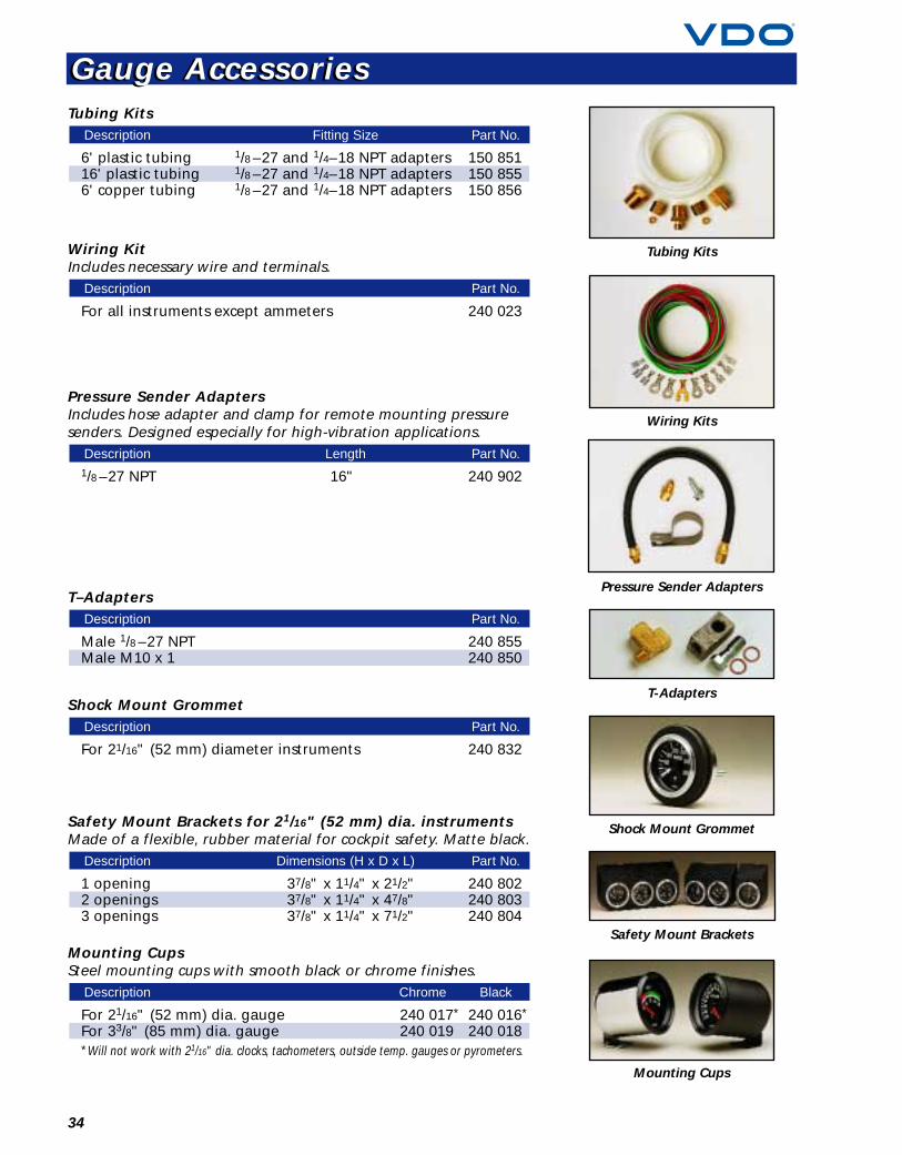
Tubing Kits
6' plastic tubing 1/8 –27 and 1/4–18 NPT adapters 150 85116' plastic tubing 1/8 –27 and 1/4–18 NPT adapters 150 8556' copper tubing 1/8 –27 and 1/4–18 NPT adapters 150 856
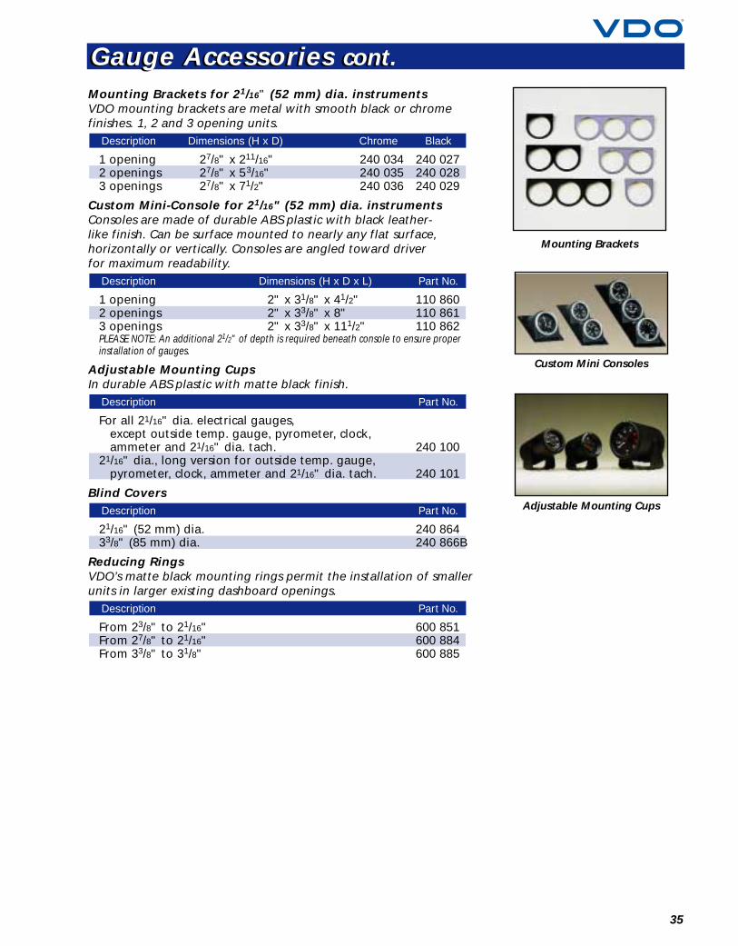
Wiring KitIncludes necessary wire and terminals.
For all instruments except ammeters 240 023
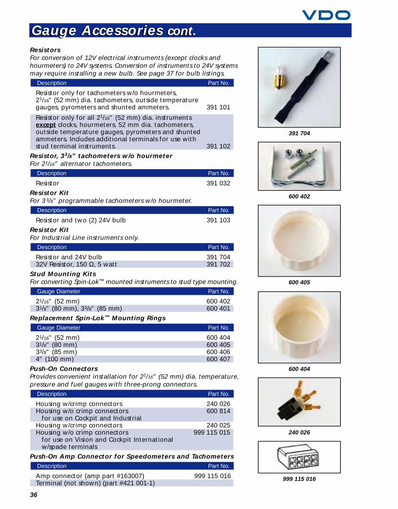
Pressure Sender AdaptersIncludes hose adapter and clamp for remote mounting pressuresenders. Designed especially for high-vibration applications.
1/8 –27 NPT 16" 240 902
T–Adapters
Male 1/8 –27 NPT 240 855Male M10 x 1 240 850
Shock Mount Grommet
For 21/16" (52 mm) diameter instruments 240 832
Safety Mount Brackets for 21/16" (52 mm) dia. instrumentsMade of a flexible, rubber material for cockpit safety. Matte black.
1 opening 37/8" x 11/4" x 21/2" 240 8022 openings 37/8" x 11/4" x 47/8" 240 8033 openings 37/8" x 11/4" x 71/2" 240 804
Mounting CupsSteel mounting cups with smooth black or chrome finishes.
For 21/16" (52 mm) dia. gauge 240 017* 240 016*
For 33/8" (85 mm) dia. gauge 240 019 240 018*Will not work with 21/16" dia. clocks, tachometers, outside temp. gauges or pyrometers.
Description Chrome Black
Description Dimensions (H x D x L) Part No.
Description Part No.
Description Part No.
Description Length Part No.
Description Part No.
Description Fitting Size Part No.
Gauge AccessoriesGauge Accessories
35
Mounting Brackets
Custom Mini Consoles
Adjustable Mounting Cups
Mounting Brackets for 21/16" (52 mm) dia. instrumentsVDO mounting brackets are metal with smooth black or chromefinishes. 1, 2 and 3 opening units.
1 opening 27/8" x 211/16" 240 034 240 0272 openings 27/8" x 53/16" 240 035 240 0283 openings 27/8" x 71/2" 240 036 240 029
Custom Mini-Console for 21/16" (52 mm) dia. instrumentsConsoles are made of durable ABS plastic with black leather-like finish. Can be surface mounted to nearly any flat surface,horizontally or vertically. Consoles are angled toward driverfor maximum readability.
1 opening 2" x 31/8" x 41/2" 110 8602 openings 2" x 33/8" x 8" 110 8613 openings 2" x 33/8" x 111/2" 110 862PLEASE NOTE: An additional 21/2" of depth is required beneath console to ensure properinstallation of gauges.
Adjustable Mounting CupsIn durable ABS plastic with matte black finish.
For all 21/16" dia. electrical gauges, except outside temp. gauge, pyrometer, clock,ammeter and 21/16" dia. tach. 240 100
21/16" dia., long version for outside temp. gauge, pyrometer, clock, ammeter and 21/16" dia. tach. 240 101
Blind Covers
21/16" (52 mm) dia. 240 86433/8" (85 mm) dia. 240 866B
Reducing RingsVDO’s matte black mounting rings permit the installation of smallerunits in larger existing dashboard openings.
From 23/8" to 21/16" 600 851From 27/8" to 21/16" 600 884From 33/8" to 31/8" 600 885
Description Part No.
Description Part No.
Description Part No.
Description Dimensions (H x D x L) Part No.
Description Dimensions (H x D) Chrome Black
Gauge Accessories cont.Gauge Accessories cont.
36
600 402
240 026
391 704
600 404
600 405
ResistorsFor conversion of 12V electrical instruments (except clocks andhourmeters) to 24V systems. Conversion of instruments to 24V systemsmay require installing a new bulb. See page 37 for bulb listings.
Resistor only for tachometers w/o hourmeters,21/16" (52 mm) dia. tachometers, outside temperaturegauges, pyrometers and shunted ammeters. 391 101
Resistor only for all 21/16" (52 mm) dia. instruments except clocks, hourmeters, 52 mm dia. tachometers,outside temperature gauges, pyrometers and shuntedammeters. Includes additional terminals for use withstud terminal instruments. 391 102
Resistor, 33/8" tachometers w/o hourmeterFor 21/16" alternator tachometers.
Resistor 391 032
Resistor KitFor 33/8" programmable tachometers w/o hourmeter.
Resistor and two (2) 24V bulb 391 103
Resistor KitFor Industrial Line instruments only.
Resistor and 24V bulb 391 70432V Resistor, 150 Ω, 5 watt 391 702
Stud Mounting KitsFor converting Spin-Lok™ mounted instruments to stud type mounting.
21/16" (52 mm) 600 40231/8" (80 mm), 33/8" (85 mm) 600 401
Replacement Spin-Lok™ Mounting Rings
21/16" (52 mm) 600 40431/8" (80 mm) 600 40533/8" (85 mm) 600 4064" (100 mm) 600 407
Push-On ConnectorsProvides convenient installation for 21/16" (52 mm) dia. temperature,pressure and fuel gauges with three-prong connectors.
Housing w/crimp connectors 240 026Housing w/o crimp connectors 600 814
for use on Cockpit and IndustrialHousing w/crimp connectors 240 025Housing w/o crimp connectors 999 115 015
for use on Vision and Cockpit Internationalw/spade terminals
Push-On Amp Connector for Speedometers and Tachometers
Amp connector (amp part #163007) 999 115 016Terminal (not shown) (part #421 001-1)
Description Part No.
Description Part No.
Gauge Diameter Part No.
Gauge Diameter Part No.
Description Part No.
Description Part No.
Description Part No.
Description Part No.
Gauge Accessories cont.Gauge Accessories cont.
999 115 016
Type A: Fits sockets #600 813, #600 816 and #600 817
9/32" 12V, 2W 600 8029/32" 24V, 3W 600 807
Type B: Fits sockets #600 818 and #600 819
11/32" 12V, 2W 600 80411/32" 12V, 4W 600 806
Type C: Fits socket #600 821
3/8" 12V, 2W 600 820Type D: (peanut type): Fits socket #600 823
Peanut bulb, 12V, 1.2W 600 809Peanut bulb, 24V, 1.2W 600 829
Type E: Fits socket #600 839
Wedge-base bulb, 12V 600 815Wedge-base bulb, 24V 600 826
INSULATED LIGHT BULB SOCKETS
3/8", uses bulb type A 600 81315/32", uses bulb type B 600 819Uses peanut-type bulb D 600 808Uses wedge-type bulb E 600 840Uses peanut-type bulb D 600 823
LIGHT BULB SOCKETS
3/8" steel, uses bulb type A 600 8163/8" brass, uses bulb type A 600 8175/8" steel, uses bulb type C 600 82115/32" steel, uses bulb type B 600 818
LIGHT DIFFUSERS The easy and convenient way to change the lighting color in yourVDO gauge. Simply slips over light bulb to give your dash a wholenew color at night.
Red, Type A, 9/32" bulb 600 853Green, Type A, 9/32" bulb 600 856Red, Type B, 11/32" bulb 600 857Green, Type B, 11/32" bulb 600 858Red, Type D, “peanut” bulb 600 859Green, Type D, “peanut” bulb 600 860Red, Types E and C bulbs 600 861Green, Types E and C bulbs 600 862
WARNING LIGHTS 12V snap-in warning lights with bulb. Requires 9/32" hole.
Red lens 600 844Green lens 600 845Yellow lens 600 846Blue lens 600 847
Description Part No.
Description Part No.
Description Part No.
Description Part No.
Description Part No.
Description Part No.
Description Part No.
Description Part No.
Description Part No.A
600 816 600 817
600 821 600 818
600 813 600 819
600 823 600 840
Light Diffusers
Warning Lights
37
B
D
E
C
Light Bulbs and SocketsLight Bulbs and Sockets

38
Technical Specifications and DimensionsTechnical Specifications and Dimensions
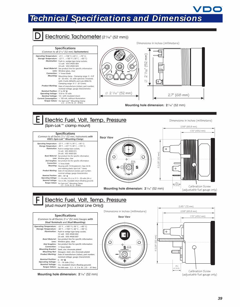
39
Technical Specifications and DimensionsTechnical Specifications and Dimensions
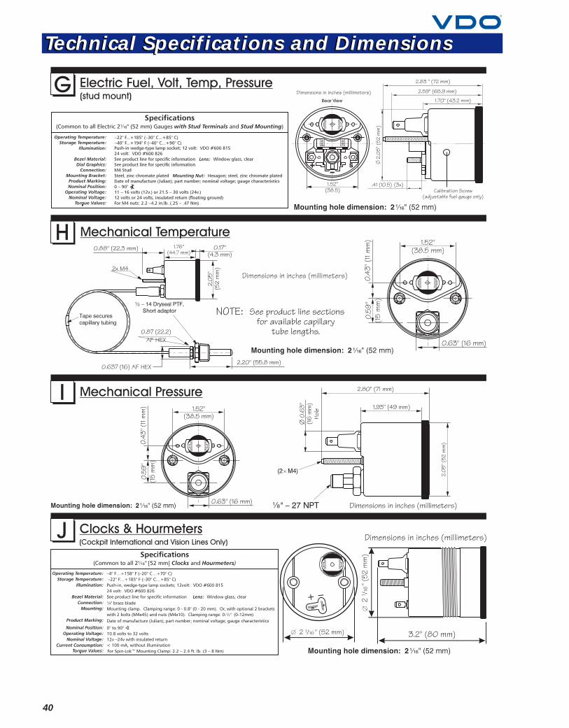
40
Technical Specifications and DimensionsTechnical Specifications and Dimensions
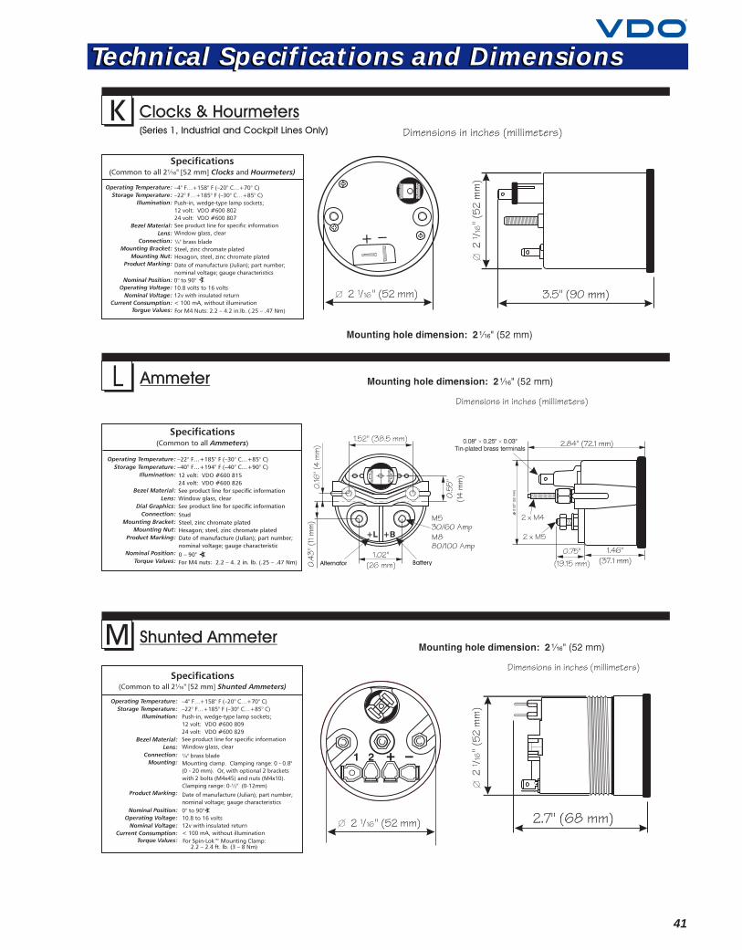
41
Technical Specifications and DimensionsTechnical Specifications and Dimensions
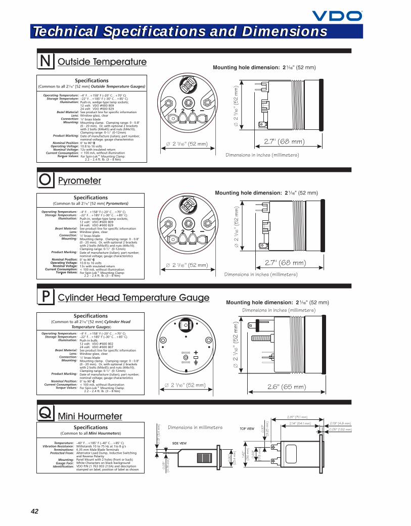
42
Technical Specifications and DimensionsTechnical Specifications and Dimensions
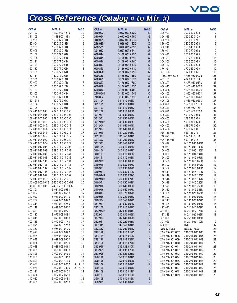
43
CAT. # MFR. # PAGE391 102 1 899 900 121D 36391 103 1 899 900 138D 36150 921 150 037 011D 9150 904 150 037 013D 9150 905 150 037 014D 9150 906 150 037 016D 9150 107 150 077 002D 13150 104 150 077 003D 13150 121 150 077 004D 13150 131 150 077 005D 13150 112 150 077 006D 13150 101 150 077 007D 13150 111 150 077 009D 13180 901 180 037 011D 8180 902 180 037 012D 8180 903 180 037 013D 8180 101 180 077 001D 12190 903 190 037 004D 10190 904 190 037 005D 10190 151B 190 075 001C 14190 104 190 077 004D 14190 105 190 077 005D 14232 011 005 003 232 011 005 003 27232 011 005 004 232 011 005 004 27232 011 005 005 232 011 005 005 27232 011 005 011 232 011 005 011 27232 011 005 012 232 011 005 012 27232 011 005 014 232 011 005 014 27232 011 005 015 232 011 005 015 27232 011 005 017 232 011 005 017 27232 011 005 020 232 011 005 020 27232 011 005 024 232 011 005 024 27232 011 017 005 232 011 017 005 27232 011 017 039 232 011 017 039 27232 011 017 041 232 011 017 041 27232 011 017 088 232 011 017 088 27232 011 017 131 232 011 017 131 27232 011 017 136 232 011 017 136 27232 011 017 139 232 011 017 139 27232 011 017 145 232 011 017 145 27232 011 019 003 232 011 019 003 27232 011 055 019 232 011 055 019 27246 068 003 001G 246 068 003 001G 25246 069 006 006G 246 069 006 006G 25600 861 3 011 002 058D 37600 862 3 011 002 065D 37240 092 3 069 000 011D 8, 12600 808 3 079 001 088D 37600 813 3 079 001 428D 37600 819 3 079 002 041D 37600 823 3 079 002 072 37600 817 3 079 003 035D 37600 816 3 079 003 080D 37600 818 3 079 003 114D 37600 821 3 079 003 121D 37240 832 3 085 001 012D 34240 027 3 088 003 048D 35240 028 3 088 003 055D 35240 029 3 088 003 062D 35240 034 3 088 003 079D 35240 035 3 088 003 086D 35240 036 3 088 003 093D 35240 828 3 092 001 016D 34240 850 3 092 001 391D 34240 855 3 092 001 418D 34180 067 3 092 001 621D 8, 12, 16180 066 3 092 001 700D 8, 12, 16600 851 3 092 002 017D 35600 884 3 092 002 055D 35340 060 3 092 003 018D 33340 061 3 092 003 025D 33
CAT. # MFR. # PAGE340 062 3 092 003 032D 33340 064 3 092 003 056D 33340 065 3 092 003 063D 33226 053 3 096 001 182D 32600 525 3 096 001 481D 32391 032 3 097 003 044 36600 844 3 108 001 012D 37600 845 3 108 001 029D 37600 846 3 108 001 036D 37600 847 3 108 001 043D 37600 853 3 126 002 091D 37600 856 3 126 002 101D 37600 860 3 126 002 156D 37600 859 3 126 002 163D 37600 857 3 126 002 170D 37600 858 3 126 002 187D 37600 814 3 130 001 046D 36240 866B 3 143 002 164B 35240 864 3 143 002 171D 35301 104 301 010 003D 13301 105 301 010 004D 13301 107 301 010 005D 13301 106 301 010 006D 13301 903 301 030 004D 9301 901 301 030 005D 9301 930B 301 030 008C 9301 904 301 040 004D 9301 902 301 040 005D 9301 015 301 220 001D 9301 303 301 260 001D 17301 302 301 260 002D 17301 301 301 260 003D 17310 105 310 010 006D 12310 106 310 010 007D 12310 107 310 010 008D 12310 151 310 015 002D 12310 909 310 030 006D 8310 915 310 030 007D 8310 907 310 030 009D 8310 911 310 030 010D 8310 934B 310 030 023C 8310 936B 310 030 024C 8310 951 310 035 002D 8310 910 310 040 006D 8310 916 310 040 007D 8310 012 310 220 002D 8310 039 310 220 003D 8310 304 310 260 002D 16331 951 331 032 002D 21332 103 332 010 002D 14332 932B 332 030 001C 10332 901 332 030 002D 10332 902 332 040 002D 10332 041 332 220 001D 10332 341 332 260 001D 17332 342 332 260 002D 17333 158 333 015 018D 12333 159 333 015 019D 12333 160 333 015 022D 12333 156 333 015 027D 12333 958 333 035 019D 8333 959 333 035 020D 8333 965 333 035 021D 8350 110 350 010 001D 13350 108 350 010 002D 13350 106 350 010 003D 13350 104 350 010 004D 13350 109 350 010 011D 13350 107 350 010 012D 13350 105 350 010 013D 13350 901 350 030 007D 9
CAT. # MFR. # PAGE350 909 350 030 009D 9350 913 350 030 010D 9350 934B 350 030 021C 9350 902 350 040 007D 9350 910 350 040 009D 9350 041 350 220 001D 9350 040 350 220 002D 9350 303 350 260 001D 16350 306 350 260 002D 16370 152 370 012 002D 14370 951 370 032 002D 10397 154 397 015 002C 124 633 030 007B 4 633 030 007B 25437 155 437 015 015D 11600 809 5 635 010 013D 37600 815 5 635 010 037D 37600 804 5 635 020 027D 37600 802 5 635 030 017D 37600 807 5 635 030 024D 37600 806 5 635 030 055D 37600 820 5 635 030 103D 37600 829 5 635 030 189 37600 826 5 635 030 206D 37600 840 999 067 001D 37600 405 999 071 001D 36600 406 999 071 002D 36600 407 999 071 003D 36600 404 999 072 001 36999 115 015 999 115 015 36240 025 999 115 015D 36999 115 016 999 115 016 36150 042 M 121 001 048D 9150 051 M 121 003 143D 9150 052 M 121 003 167D 9150 030 M 121 004 144D 9150 505 M 121 015 056D 19150 506 M 121 015 063D 19150 507 M 121 015 070D 19150 508 M 121 015 087D 19150 511 M 121 015 111D 19150 513 M 121 015 180D 19150 514 M 121 015 197D 19150 518 M 121 015 245D 19150 520 M 121 015 269D 19150 510 M 121 015 348D 19150 306 M 121 020 065D 16150 302 M 121 020 089D 17180 317 M 131 020 079D 16180 308 M 131 020 093D 16437 052 M 211 012 073D 7437 053 M 211 012 176D 7437 353 M 211 020 023D 15301 030 M 251 006 085D 9301 036 M 251 006 157D 9600 803 N/A 37N03 321 008 N03 321 008 22X10 246 001 007 X10 246 001 007 25X10 246 001 008 X10 246 001 008 25X10 246 001 009 X10 246 001 009 25X10 246 001 010 X10 246 001 010 25X10 246 001 011 X10 246 001 011 25X10 246 001 012 X10 246 001 012 25X10 246 001 013 X10 246 001 013 25X10 246 001 014 X10 246 001 014 25X10 246 001 015 X10 246 001 015 25X10 246 001 016 X10 246 001 016 25X10 246 001 017 X10 246 001 017 25X10 246 001 018 X10 246 001 018 25X10 246 001 019 X10 246 001 019 25
Cross Reference (Catalog # to Mfr. #)Cross Reference (Catalog # to Mfr. #)

02/2001
VDO North America LLC
188 Brooke Road, P.O. 2897, Winchester, VA 22604Telephone 540-665-2428 / Fax 540-722-4198 / www.vdona.com
Be sure to check out our new products on pages 5 and 22-26.
The 230 Series Heavy-DutyPressure Switch
The VDO WindshieldWasher System
The BAI (Bus AnalogInterface) System
The D‘Mac System
Severe Duty
Distributed by: