GIUNTI LAMELLARI FLESSIBILI FLEXIBLE ALL STEEL … · Coupling selection Scelta del giunto in ......
30
GIUNTI LAMELLARI FLESSIBILI FLEXIBLE ALL STEEL COUPLINGS
Transcript of GIUNTI LAMELLARI FLESSIBILI FLEXIBLE ALL STEEL … · Coupling selection Scelta del giunto in ......
GIUNTI LAMELLARI FLESSIBILI FLEXIBLE ALL STEEL COUPLINGS

Giunti lamellari tipo “RSP”.Flexible all steel couplings type “RSP”.
Giunti lamellari tipo “RPA”.Flexible all steel couplings type “RPA”.
Giunti lamellari tipo “RSL mc”.Flexible all steel couplings type “RSL mc”.
Giunti lamellari tipo “RPD”.Flexible all steel couplings type “RPD”.
GIUNTI LAMELLARI FLESSIBILIFLEXIBLE ALL STEEL COUPLINGS

L’AZIENDAABOUT US
INDICEINDEX
6789
1011121314151617181920212223
5432
2425
Caratteristichecharacteristics
Dati tecniciTecnical data
Scelta del giuntoCoupling selection
Scelta del giunto in base a kw e in n° giriCoupling selection according to kw and rpm
Giunto RSCoupling RS
Giunto RSDCoupling RSD
Giunto RSACoupling RSA
Giunto RSM semplice e doppioCoupling RSM simple and double
Giunto RPCoupling RP
Giunto RPDCoupling RPD
Giunto RPACoupling RPA
Giunto RSPCoupling RSP
Giunto RPCoupling RP
Giunto RPDCoupling RPD
Giunto RSPCoupling RSP
Esecuzioni specialiSpecial executions
Giunto RSLCoupling RSL
Giunto RSLDCoupling RSLD
Giunto RSLECoupling RSLE
Giunto RSLICoupling RSLI
Giunto RSL mcCoupling RSL mc
Esecuzioni specialiSpecial executions
Indicazioni generali per il montaggio e l’allineamento
General guide-lines for assembly and alignement
GIU
NTI
A 4
VIT
ICO
UPLI
NG
S W
ITH
4 B
OLT
SA 6
VIT
IW
ITH
6 B
OLT
SA 6
VIT
IW
ITH
6 B
OLT
SA 8
VIT
IW
ITH
8 B
OLT
S
Una forte tradizione
Alla RU-STEEL siamo specializzati nello studio e nellacostruzione di giunti di trasmissione. Una esperienza matu-rata alla fine degli anni cinquanta, ci ha consentito di real-izzare prodotti di assoluta competitività e affermare con suc-cesso la nostra presenza nel mercato nazionale ed estero.
Un impegno verso la qualità e la tecnologia
Sin dal primo giunto la filosofia della RU-STEEL è statadi progettare e costruire una gamma completa di giunti ditrasmissione (da Nm 3 a 300.000, che va dai “giuntielastici” ai “giunti a denti autolubrificanti” ai “giuntilamellari” ai “giunti super elastici”) tali da soddisfaretutte le richieste del cliente. Questa filosofia è diventataper il nostro engineering un costante impegno nel per-fezionare i prodotti in modo di garantire all’utilizzatore lamassima funzionalità, durata ed economicità.
Una presenza sicura
Alla RU-STEEL con il continuo miglioramento della pro-duzione, un’attenta politica di marketing ed una rete didistribuzione ed assistenza sempre più qualificata, siamovicini alle esigenze della clientela che ci ripaga ognigiorno restandoci affezionata. Per questo la RU-STEEL èorgogliosa di presentarVi il nuovo catalogo dei “Giuntilamellari flessibili”.
A strong tradition
RU-STEEL is specialized in designing and manufacturingtrasmissiong couplings. An experience matured at the endof the fifties al-lowed us to realize absolutely competitiveproducts and to assert successfully our presence both onthe inland and foreign market.
An engagement towards quality and technology
Since the first coupling produced, RU-STEEL’s philoso-phy has been designig and manufacturing a completerange of trasmission couplings (from Nm 3 to 300.000,including “elastic couplings”, “self-lubricating coupling”,“flexible couplings”, “super elastic coupling”) in order tomeet all customer’s requestes; This philosophy hasbecome, for our engineering, a steady engagement in per-fectioning our products in order to guarantee the highestfuntionallity, life and inexpensiveness to the user.
A reliable presence
By means of the steady production improvement, of a care-ful marketing policy and of a more and more qualified dis-tribution and service network, at RU-STEEL we are close tothe requiriments of our customers, who reward us daily withtheir faithfulness. RU-STEEL is therefore pride to presentyou our new catalogue about “Flexible all steel couplings”.
�
�

2
� Alta coppia trasmissibile con peso limitato
� Esecuzione completamente metallica(C45-AISI 304)
� Disponibili esecuzioni completamente inAISI 304 e AISI 316 (su richiesta)
� Libertà di spostamento assiale degli alberie possibilità di regolazione della corsa assiale
� Rigidità torsionale senza giochi anchecon repentine inversioni di coppia
� Possibilità di funzionamento in amboi sensi di rotazione
� Possibilità di funzionamento in avversecondizioni ambientali
� Possibilità di impiego non limitatoda alte temperature
� Angolo cardanico
� Limitato carico di spinta
� Spostamento parallelo degli alberi
� Nessuna necessità di manutenzione
� Durata illimitata
� Esecuzione a norme API 610 (671 su richiesta)
� Esecuzione antiscintilla
� Bilanciatura a Norme ISO 1940-73
� High torque capacity with low weight
� Complete metallic construction(C45-AISI 304)
� Also available executions made completely inAISI 304 and AISI 316 (by request)
� Axial misalignment with possibility to adjustthe axial stroke
� Torsional stiffness shug also with reversal torque
� Operation in both directions of rotation
� Operation in adverse environmental conditions
� High temperature operation
� Angular misalignment
� Limited axial thrust
� Parallel misalignment
� No lubrication of any kind is required
� No maintenance
� Long working Life
� Execution to API 610 (671 by request)
� No Sparking execution
� Balancing to ISO 1940-73
CARATTERISTICHECHARACTERISTICS

DATI TECNICITECHNICAL DATA
GrandezzaSize
Coppia nominaleNomina torque
TknNm
Velocità maxMax speed
RPM(1/min)
Senza spaziatoreWithout spacer
Nm x 106
rad
Con spaziatoreWith spacerNm x 106
rad
Angolare maxsenza spaziatore
Max angularwithout spacer
°
Angolare maxcon spaziatoreMax angularwith spacer
°
Assiale maxsenza spaziatore
Max axialwithout spacer
mm.
Assiale maxcon spaziatore
Max axialwith spacer
mm.
Parallelo maxcon spaziatoreMax parallelwith spacer
± mm.
Spinta assialeAxial trust
Kg.
Coppiaserraggio viti
Bolts tighteningtorque
Nm
H
Y
X
Z
0
1
2
2,5
3
5
7
12
20
10
15
30
70
110
170
260
400
700
900
1200
1500
2000
2500
3500
5000
6500
8000
10000
13000
16000
20000
25000
30000
13
16
27
59
109
196
3
8
14
27
59
122
263
425
507
667
843
1.264
1.985
98
147
294
687
1.079
1.668
2.551
3.924
6.867
8.829
11.772
14.715
19.620
24.525
34.335
49.050
63.765
78.480
98.100
127.530
156.960
196.200
245.250
294.300
127
157
265
588
1.069
1.922
5000
5000
5000
5000
4500
4500
4000
11000
10800
10600
10300
10000
9800
95009000
8500
7500
6500
6000
5800
5500
5000
4500
4000
3900
3700
3400
3100
2900
2800
2600
11000
10800
106008500
8000
7000
0,015
0,022
0,037
0,05
0,173
0,285
0,391
0,681
0,853
1,091
1,476
1,95
4,245
0,112
0,149
0,396
0,924
1,759
2,136
3,344
8,563
11,373
13,48
14,782
15,628
21,262
36,965
49,126
61,278
69,363
89,437
111,872
172,158
196,515
244,375
295,366
328,988
0,129
0,162
0,371
0,795
1,605
2,622
0,007
0,01
0,016
0,022
0,077
0,124
0,178
0,29
0,388
0,485
0,642
0,848
1,846
0,049
0,068
0,176
0,402
0,765
0,971
1,52
3,806
4,945
5,738
6,427
6,946
9,45
15,637
22,033
26,643
31,529
39,75
48,64
76,47
87,34
106,25
128,42
149,54
0,054
0,072
0,158
0,346
0,698
1,116
1
1
1
1
1
1
1
1
1
1
1
1
1
0,75
0,75
0,75
0,75
0,75
0,75
0,75
0,75
0,75
0,75
0,75
0,75
0,5
0,5
0,5
0,5
0,5
0,5
0,5
0,5
0,5
0,5
0,5
0,5
0,75
0,75
0,75
0,75
0,75
0,75
2
2
2
2
2
2
2
2
2
2
2
2
2
1,5
1,5
1,5
1,5
1,5
1,5
1,5
1,5
1,5
1,5
1,5
1,5
1
1
1
1
1
1
1
1
1
1
1
1
1,5
1,5
1,5
1,5
1,5
1,5
0,4
0,5
0,65
0,9
1,45
1,6
1,95
2,1
2,65
2,95
3,3
3,9
4,05
0,85
1
1,3
1,5
1,75
2,1
2,4
2,6
2,6
2,65
2,9
2,95
3,15
3,3
3,5
3,8
4,3
4,45
4,6
4,75
5,05
5,4
5,8
6,25
0,95
1,1
1,2
1,45
1,7
2,15
0,8
1
1,3
1,8
2,9
3,2
3,9
4,2
5,3
5,9
6,6
7,8
8,1
1,7
2
2,6
3
3,5
4,2
4,8
5,2
5,2
5,3
5,8
5,9
6,3
6,6
7
7,6
8,6
8,9
9,2
9,5
10,1
10,8
11,6
12,5
1,9
2,2
2,4
2,9
3,4
4,3
0,1
0,15
0,3
0,4
0,6
0,7
0,8
0,9
1
1,1
1,2
1,3
1,6
0,3
0,4
0,5
0,7
0,8
0,9
0,9
1,4
1,4
1,4
1,4
1,4
1
1,2
1,6
1,7
1,8
1,9
2
2,1
2,3
2,5
2,6
2,8
0,3
0,4
0,5
0,6
0,7
0,9
2
4
8
15
25
30
37
49
58
75
80
100
145
15
20
27
36
55
72
78
106
118
145
285
379
458
560
740
790
860
990
1100
1200
1380
1600
1800
1980
18
22
26
33
52
75
1
2,2
4,5
7,5
7,5
7,5
39
39
71
71
71
113
189
7,8
7,8
20
41
76
76
118
260
368
922
922
922
922
922
1255
1570
2750
2840
2980
3100
3840
4250
5840
6245
6
6
10
25
52
95
Giun
ti a
4 vi
tiCo
uplin
gs w
ith 4
bol
tsGi
unti
a 6
viti
Coup
lings
with
6 b
olts
Giun
ti a
8 vi
tiCo
uplin
gs w
ith 8
bol
tsGi
unti
a 6
viti
Coup
lings
with
6 b
olts
Rigità torsionale - Torsional stiffness Disallineamento - Misalignment
NoteLa rigidità torsionale é data per dimensioni a catalogo e si riferisce ai par-ticolari compresi tra le flange dei mozzi. Sia il Disassamento Assiale chequello Parallelo devono essere presi in considerazione combinati datoche uno si riduce se aumenta l’altro. Le velocità massime ammesse sonocalcolate con i componenti principali (mozzi,adattori,spaziatori ecc.)costruiti in acciaio al carbonio e con dimensioni di catalogo. Per veloci-tà di esercizio superiori o sono usati acciai superiori o sono usati acciaispeciali o vengono eseguiti speciali studi.
NotesTorsional stiffness is given between hub flanges for standard dimen-sion. Both Axial and Parallel misalignment must be considered incombination as one will reduce with an increase in the other.Maximum speed for main components in Mild Steel and of standarddimensions machined from solid. For higher operational speed alter-native materials or designs are available.
Per trovare il valore di spinta assiale (con una approssimazione del 20%in più o in meno) in base al disassamento assiale servirsi della tabella chesegue tenendo presente che per valore in percentuale di disassamentoassiale (asse y) corrisponderà un valore in percentuale di spinta (asse x).
To find the axial thrust (with anapproximation of 20% more orless) on the grounds of axialmisalignment to use the follo-wing table bearing in mind thatfor a pecent value of the axialmisalignment (y) will corresponda percent value of the axialthrust (x).
100X
Y100
75
50
25
00 25 50 75
SPINTA ASSIALEMAX AXIAL TRUST
DIS
ALL
INEAM
EN
TO M
ASSIM
OM
ISALI
GN
EM
EN
T M
AX
3
5000
50005000
500050005000

La tabella riportata dà una guida approssimativa dei fattori di sevizio per applicazioni generali, per fattori più specifici
si raccomanda di consultare le norme AGMA 922-A96 o norme similari, oppure consultare il nostro ufficio tecnico.
The table gives a rough guide to service factors of general applications. For more specific figures it is recommended
that AGMA 922-A96 or similar reference should be consulted, or reference made to our technical department.
4
Alternative always using the maximum power and the RPM is pos-sible find the coupling’s nominal torque ad compare the resultingvalues to the dates showed on the column “nominal torque”.
B) Determination of the coupling size with the choice of the nom-inal torque in Nm.
Kw x 9550
giri/1’ (di esercizio)
Kw
giri/1’ (di esercizio)P.za Nominale = X fattore di servizio
coppia Spunto
2 x coppia nom.
Per selezionare la grandezza del giunto è indispensabile consid-erare la potenza massima della macchina motrice anziché lapotenza assorbita dalla macchina condotta, sempre che questaultima non sia superiore. Dopo avere determinato i Kw massimi datrasmettere questi vengono riportati alla velocità di 1 giro /1’.Paragonando il valore ottenuto con quelli indicati nella colonna“N/n” si ottiene una prima selezione.
A) Selezione della grandezza del giunto con scelta dei valori a 1 giro /1’
Coppia Nominale = X fattore di servizio
Kw
giri/1’ (di esercizio)P.za Nominale = X fattore di servizio
X
Kw X 9550
giri/1’ (di esercizio)Coppia Nominale = X fattore di servizio
coppia Spunto
2 x coppia nom.X
In alternativa considerando sempre la potenza massima e ilnumero di giri /1’ è possibile trovare la coppia nominale del giun-to e quindi paragonare il valore ottenuto con la colonna “Nm”.
B) Selezione della grandezza del giunto con scelta della coppianominale in Nm.
Il giunto a catalogo sopporta una coppia di spunto pari a due voltela nominale, se superiore selezionare il giunto nei seguenti modi:
KW x 9550
RPM (of operation)
KW
RPM (of operation)Nominal Power = X service factor
starting torque
2 nominal torque
For the choice of the coupling size it is advisable to use the actualavailable power of the driving machine rather than the calculatedadsorbed power of the driven machine, unless this latter is know not tobe exceed. After having determined the maximum… Kw that should betransmitted, these ones are brought back to 1 RPM of speed.Comparing the resulting values to the dates showed on the column“N/n” it had a first selection.
A) Determination of the coupling size with the choice of the values at 1 RPM
Nominal Torque = X service factor
KW
RPM (of operation)Nominal Power = X service factor
X
KW x 9550
RPM (of operation)Starting Torque = X service factor
starting torque
2 nominal torqueX
The couplings listed in the catalogue supports a starting torqueequal to twice the nominal torque, if it is higher then 2 the cou-pling must be choose as follows:
UNIFORMEUNIFORM
LEGGEROLIGHT
MEDIOMEDIUM
PESANTEHIGH
COSTANT TORQUECentrifugal pump, light conveyors,alternators, centrifugal compressor
SLIGT TORQUE FLUCTATIONMachine tools, screw compressors,screw pumps, liquid ring compressors
TORQUE FLUCTATIONReciprocating pumps, low viscositymixers, cranes
EXCEPTIONALLY HIGH TORQUEFLUCTUACTIONSRotary presses, reciprocatingcompressors, high viscosity mixers
1.0 1.25 2.0
1.5 2.0 2.5
2.0 2.5 3.0
2.5 3.0 4.0
SCELTA DEL GIUNTOCOUPLING SELECTION
Per motori con avviamento in diretta, con coppia di spunto non supe-rione di due volte la nominale, si dovrà applicare un fattore di serviziominimo di 1,5. Per coppie di spunto superiori applicare le formulesoprastanti. Come controllo finale è necessario assicurarsi che i foriammessi siano adeguati agli alberi su cui il giunto andrà montato.
For direct on line starts motors, where the starting torque does notexceed twice the nominal torque, must be applied a service factoras 1,5. For starting torque higher use the above formulas.A final check should be made to ensure that, the maximum borehub bore dimension is adequate for the shaft.
Like A)
Like B)
Come da A)
Come da B)
FATTORI DI SERVIZIO
Macchine a vaporeTurbine ad acqua
Steam EngineWater turbine
MotoriDiesel
Oil Engine
Motori elettriciTurbine a gas o a vapore
Electric motorsSteam gas or turbine
COPPIA COSTANTEPompe centrifughe, piccoli convettori,alternatori, compressori centrifughi
COPPIA POCO FLUTTUANTEMacchine utensili, pompe a vite, compres-sori a vite, compressori ad anello liquido
COPPIA FLUTTUANTEPompe alternative, miscelatoria bassa viscosità, gru
COPPIA ALTA CONFLUTTUAZIONI ECCEZIONALIPresse rotanti compressori alternativi,miscelatori ad alta viscosità
SERVICE FACTOR
SCELTA DEL GIUNTO IN BASE A KW E N° GIRICOUPLING SELECTION ACCORDING TO KW AND RPM
TipoType
CoppiaNominaleNominaltorqueTknNm
1 10 100 300 500 750 1000 1200 1500 1800 2000 2600 3000 3600 4000 5000
5
H
Y
X
Z
0
1
2
2,5
3
5
7
12
20
10
15
30
70
110
170
260
400
700
900
1200
1500
2000
2500
3500
5000
6500
8000
10000
13000
16000
20000
25000
30000
13
16
27
59
109
196
3
8
14
27
59
122
263
425
507
667
843
1.264
1.985
98
147
294
687
1.079
1.668
2.551
3.924
6.867
8.829
11.772
14.715
19.620
24.525
34.335
49.050
63.765
78.480
98.100
127.530
156.960
196.200
245.250
294.300
127
157
265
588
1.069
1.922
0,0003
0,0008
0,0015
0,0028
0,0062
0,0128
0,0247
0,0445
0,0531
0,0698
0,0883
0,1324
0,2079
0,0103
0,0154
0,0308
0,0719
0,1130
0,1747
0,2671
0,4109
0,7191
0,9245
1,2327
1,5408
2,0545
2,5681
3,5953
5,1361
6,6770
8,2178
10,272
13,354
16,436
20,545
25,681
30,817
0,0133
0,0164
0,0277
0,0616
0,1119
0,2013
0,003
0,008
0,015
0,028
0,062
0,128
0,247
0,445
0,531
0,698
0,883
1,324
2,079
0,103
0,154
0,308
0,719
1,130
1,747
2,671
4,109
7,191
9,245
12,33
15,41
20,54
25,68
35,36
51,36
66,77
82,18
102,7
133,5
164,4
205,4
256,8
308,2
0,133
0,164
0,277
0,616
1,119
2,013
0,03
0,08
0,15
0,28
0,62
1,28
2,47
4,45
5,31
6,98
8,83
13,2
20,8
1,03
1,54
3,08
7,19
11,3
17,5
26,7
41,1
71,9
92,5
123,3
154,1
205,4
256,8
359,5
513,6
667,7
821,8
1.027
1.335
1.644
2.054
2.568
3.082
1,33
1,64
2,77
6,16
11,19
20,13
0,09
0,25
0,44
0,85
1,85
3,83
7,41
13,4
15,9
21,0
26,5
39,7
62,4
3,08
4,62
9,24
21,6
33,9
52,4
80,1
123
216
277
370
462
616
770
1.079
1.541
2.003
2.465
3.082
4.006
4.931
6.163
7.704
9.245
3,99
4,93
8,32
18,5
33,6
60,4
0,16
0,42
0,73
1,41
3,09
6,39
12,4
22,3
26,5
34,9
44,1
66,2
104
5,13
7,70
15,4
36,0
56,5
87,3
134
205
360
462
616
770
1.027
1.284
1.798
2.568
3.338
4.109
5.136
6.677
8.218
10.272
12.840
15.408
6,65
8,22
13,9
30,8
56,0
101
0,24
0,63
1,10
2,12
4,63
9,58
18,5
33,4
39,8
52,4
66,2
99,3
156
7,70
11,5
23,1
54,0
84,7
131
200
308
539
693
925
1.156
1.541
1.926
2.696
3.852
5.008
6.163
7.704
10.015
12.327
15.408
19.260
23.113
9,97
12,3
20,8
46,2
84,0
151
0,31
0,84
1,47
2,83
6,18
12,8
24,7
44,5
53,1
69,8
88,3
132
208
10,3
15,4
30,8
71,9
113
175
267
411
719
925
1.233
1.541
2.054
2.568
3.595
5.136
6.677
8.218
10.272
13.354
16.436
20.545
25.681
30.817
13,3
16,4
27,7
61,6
112
201
0,38
1,01
1,76
3,39
7,41
15,3
29,7
53,4
63,7
83,8
106
159
249
12,3
18,5
36,9
86,3
136
210
321
493
863
1.109
1.479
1.849
2.465
3.083
4.314
6.163
8.012
9.861
12.327
16.025
19.723
24.653
30.817
36.980
16,0
19,7
33,3
73,9
134
242
0,47
1,26
2,20
4,24
9,27
19,2
37,1
66,8
79,6
105
132
199
312
15,4
23,1
46,2
108
169
262
401
616
1.079
1.387
1.849
2.311
3.082
3.852
5.393
7.704
10.015
12.327
15.408
20.031
24.653
30.817
38.521
46.225
19,9
24,7
41,6
92,4
168
302
0,57
1,51
2,64
5,09
11,1
23,0
44,5
80,1
95,6
126
159
238
374
18,5
27,7
55,4
129
2,3
314
481
740
1.294
1.664
2.219
2.774
3.698
4.623
6.472
9.245
12.019
14.792
18.490
24.037
29.584
36.980
-
-
23,9
29,6
49,9
111
201
362
0,69
1,84
3,23
6,22
13,6
28,1
54,4
97,9
117
154
194
291
457
22,6
33,9
67,7
158
249
384
588
904
1.582
2.034
2.712
3.390
4.520
5.650
7.910
11.299
14.689
18.079
22.599
29.379
-
-
-
-
29,3
36,2
61,0
135
246
443
0,82
2,18
3,81
7,35
16,1
33,2
64,3
116
138
182
230
344
540
26,7
40,0
80,0
187
294
454
695
1.068
1.870
2.404
3.205
4.006
5.342
6.677
9.348
13.354
17.360
21.366
26.708
-
-
-
-
-
34,6
42,7
72,1
160
291
523
0,94
2,51
4,40
8,48
18,5
38,3
74,1
134
159
210
265
397
624
30,8
46,2
92,4
216
339
524
801
1.233
2.157
2.774
3.698
4.623
6.163
7.704
10.786
15.408
20.031
24.653
-
-
-
-
-
-
39,9
49,3
83,2
185
336
604
1,13
3,02
5,28
10,2
22,2
46,0
89,0
160
191
251
318
476
748
36,9
55,4
111
259
407
629
962
1.479
2.589
3.328
4.438
5.547
7.396
9.245
12.943
18.490
24.037
-
-
-
-
-
-
-
47,9
59,2
99,9
222
4,3
725
1,26
3,35
5,86
11,3
24,7
51,1
98,8
178
212
279
353
529
-
41,0
61,6
123
288
452
699
1.068
1.644
2.876
3.698
4.931
-
8.218
10.272
14.381
20.545
-
-
-
-
-
-
-
-
53,2
65,8
111
246
448
-
1,57
4,19
7,33
14,1
30,9
63,9
123,6
223
265
349
441
-
-
51,3
77,0
154
360
565
873
1.336
2.054
3.595
4.623
-
-
10.272
12.840
17.976
-
-
-
-
-
-
-
-
-
66,5
82,2
139
308
-
-
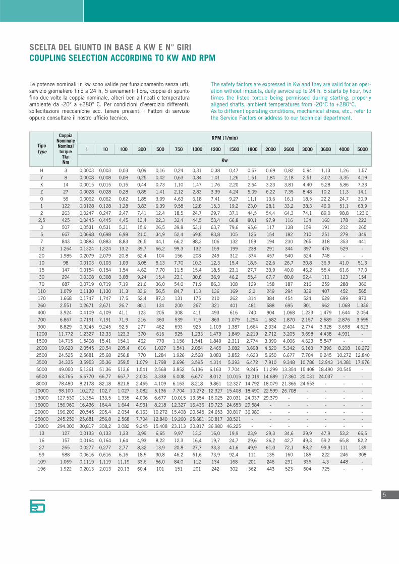
Le potenze nominali in kw sono valide per funzionamento senza urti,servizio giornaliero fino a 24 h, 5 avviamenti l’ora, coppia di spuntofino due volte la coppia nominale, alberi ben allineati e temperaturaambiente da -20° a +280° C. Per condizioni d’esercizio differenti,sollecitazioni meccaniche ecc. tenere presenti i Fattori di serviziooppure consultare il nostro ufficio tecnico.
The safety factors are expressed in Kw and they are valid for an oper-ation without impacts, daily service up to 24 h, 5 starts by hour, twotimes the listed torque being permissed during starting, properlyaligned shafts, ambient temperatures from -20°C to +280°C.As to different operating conditions, mechanical stress, etc., refer tothe Service Factors or address to our technical department.
RPM (1/min)
Kw
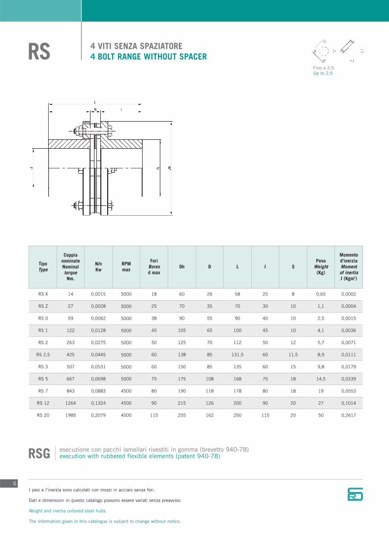
4 VITI SENZA SPAZIATORE4 BOLT RANGE WITHOUT SPACERRS
TipoType
CoppianominaleNominaltorqueNm.
N/nKw
RPMmax
ForiBoresd max
Dh D L I SPeso
Weight(Kg)
Momentod’inerziaMomentof inertiaJ (Kgm2)
I pesi e l’inerzia sono calcolati con mozzi in acciaio senza fori.
Dati e dimensioni in questo catalogo possono essere variati senza preavviso.
Weight and inertia unbored steel hubs.
The information given in this catalogue is subject to change without notice.
6
RS X
RS Z
RS 0
RS 1
RS 2
RS 2,5
RS 3
RS 5
RS 7
RS 12
RS 20
14
27
59
122
263
425
507
667
843
1264
1985
0,0015
0,0028
0,0062
0,0128
0,0275
0,0445
0,0531
0,0698
0,0883
0,1324
0,2079
5000
5000
5000
5000
5000
5000
5000
5000
4500
4500
4000
18
25
38
45
50
60
60
75
80
90
115
60
70
90
105
125
138
150
175
190
215
255
26
35
55
65
70
85
85
108
118
126
162
58
70
90
100
112
131,5
135
168
178
200
250
25
30
40
45
50
60
60
75
80
90
115
8
10
10
10
12
11,5
15
18
18
20
20
0,65
1,1
2,5
4,1
5,7
8,9
9,8
14,5
19
27
50
0,0002
0,0004
0,0015
0,0036
0,0071
0,0111
0,0179
0,0339
0,0553
0,1014
0,2617
esecuzione con pacchi lamellari rivestiti in gomma (brevetto 940-78)execution with rubbered flexible elements (patent 940-78)RSG
Fino a 2,5Up to 2,5
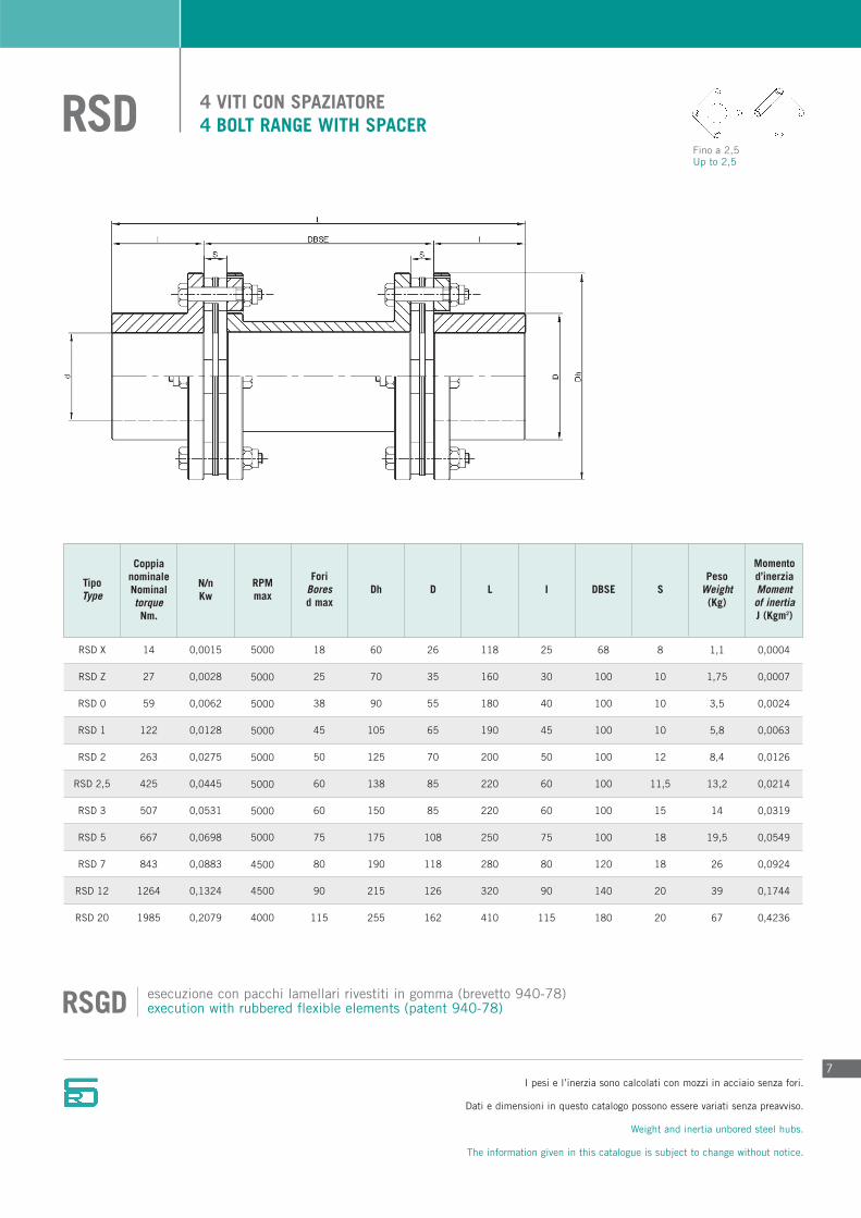
4 VITI CON SPAZIATORE4 BOLT RANGE WITH SPACERRSD
I pesi e l’inerzia sono calcolati con mozzi in acciaio senza fori.
Dati e dimensioni in questo catalogo possono essere variati senza preavviso.
Weight and inertia unbored steel hubs.
The information given in this catalogue is subject to change without notice.
7
TipoType
CoppianominaleNominaltorqueNm.
N/nKw
RPMmax
ForiBoresd max
Dh D L I DBSE S
Momentod’inerziaMomentof inertiaJ (Kgm2)
PesoWeight
(Kg)
RSD X
RSD Z
RSD 0
RSD 1
RSD 2
RSD 2,5
RSD 3
RSD 5
RSD 7
RSD 12
RSD 20
14
27
59
122
263
425
507
667
843
1264
1985
0,0015
0,0028
0,0062
0,0128
0,0275
0,0445
0,0531
0,0698
0,0883
0,1324
0,2079
5000
5000
5000
5000
5000
5000
5000
5000
4500
4500
4000
18
25
38
45
50
60
60
75
80
90
115
60
70
90
105
125
138
150
175
190
215
255
26
35
55
65
70
85
85
108
118
126
162
118
160
180
190
200
220
220
250
280
320
410
25
30
40
45
50
60
60
75
80
90
115
68
100
100
100
100
100
100
100
120
140
180
8
10
10
10
12
11,5
15
18
18
20
20
1,1
1,75
3,5
5,8
8,4
13,2
14
19,5
26
39
67
0,0004
0,0007
0,0024
0,0063
0,0126
0,0214
0,0319
0,0549
0,0924
0,1744
0,4236
esecuzione con pacchi lamellari rivestiti in gomma (brevetto 940-78)execution with rubbered flexible elements (patent 940-78)RSGD
Fino a 2,5Up to 2,5
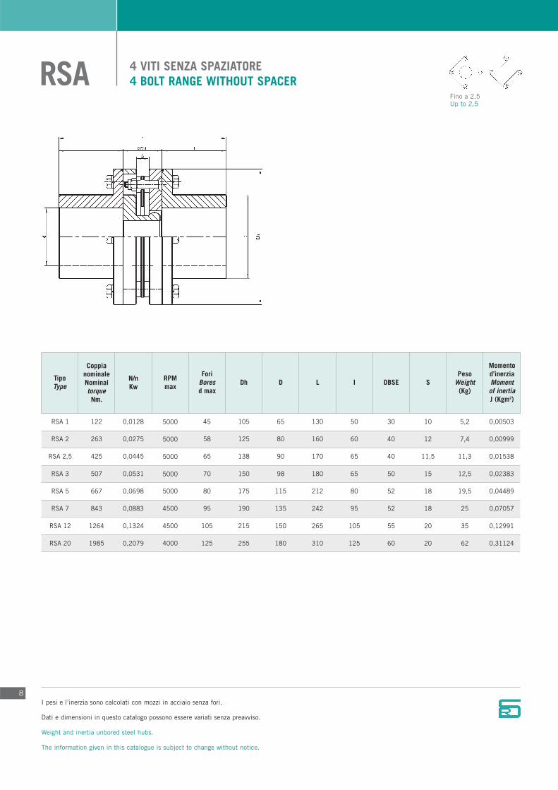
4 VITI SENZA SPAZIATORE4 BOLT RANGE WITHOUT SPACERRSA
TipoType
CoppianominaleNominaltorqueNm.
N/nKw
RPMmax
ForiBoresd max
Dh D L I DBSE S
Momentod’inerziaMomentof inertiaJ (Kgm2)
PesoWeight
(Kg)
I pesi e l’inerzia sono calcolati con mozzi in acciaio senza fori.
Dati e dimensioni in questo catalogo possono essere variati senza preavviso.
Weight and inertia unbored steel hubs.
The information given in this catalogue is subject to change without notice.
8
RSA 1
RSA 2
RSA 2,5
RSA 3
RSA 5
RSA 7
RSA 12
RSA 20
122
263
425
507
667
843
1264
1985
0,0128
0,0275
0,0445
0,0531
0,0698
0,0883
0,1324
0,2079
5000
5000
5000
5000
5000
4500
4500
4000
45
58
65
70
80
95
105
125
105
125
138
150
175
190
215
255
65
80
90
98
115
135
150
180
130
160
170
180
212
242
265
310
50
60
65
65
80
95
105
125
30
40
40
50
52
52
55
60
10
12
11,5
15
18
18
20
20
5,2
7,4
11,3
12,5
19,5
25
35
62
0,00503
0,00999
0,01538
0,02383
0,04489
0,07057
0,12991
0,31124
Fino a 2,5Up to 2,5

SEMPLICE. 4 VITI, REALIZZATO IN ALLUMINIOSIMPLE. 4 BOLT RANGE, MADE OF ALUMINIUMRSM
I pesi e l’inerzia sono calcolati con mozzi in acciaio senza fori.
Dati e dimensioni in questo catalogo possono essere variati senza preavviso.
Weight and inertia unbored steel hubs.
The information given in this catalogue is subject to change without notice.
9
TipoType
CoppianominaleNominaltorqueNm.
N/nKw
RPMmax
ForiBores
D2 max
A B C E F
Momentod’inerziaMomentof inertiaJ (Kgm2)
PesoWeight
(gr.)
RSM H
RSM Y
RSM X
RSM Z
3
8
14
27
0,0003
0,0008
0,0015
0,0028
5000
5000
5000
5000
8
14
19
25
8
14
28
35
9
10
11
12
41
46
53
54
25
35
30
35
16
18
21
21
25
35
53
68
60
110
200
600
0,000005
0,000022
0,000081
0,000320
DOPPIO. 4 VITI, REALIZZATO IN ALLUMINIODOUBLE. 4 BOLT RANGE, MADE OF ALUMINIUMRSM
RSM H
RSM Y
RSM X
RSM Z
3
8
14
27
0,0003
0,0008
0,0015
0,0028
5000
5000
5000
5000
8
14
19
25
8
14
28
35
22
24
26
70
54
60
68
68
25
35
30
35
16
18
21
21
25
35
55
68
80
140
260
900
0,000006
0,000030
0,000100
0,000720
D1 max

6 VITI SENZA SPAZIATORE6 BOLT RANGE WITHOUT SPACERRP
TipoType
CoppianominaleNominaltorqueNm.
N/nKw
RPMmax
ForiBores
d1 maxDh D1 L I S
PesoWeight
(Kg)
Momentod’inerziaMomentof inertiaJ (Kgm2) d2 max D2
10
RP 10
RP 15
RP 30
RP 70
RP 110
RP 170
RP 260
RP 400
RP 700
RP 900
RP 1200
RP 1500
98
147
294
687
1079
1668
2551
3924
6867
8829
11772
14715
0,010
0,015
0,031
0,072
0,113
0,175
0,267
0,411
0,719
0,925
1,233
1,541
11000
10800
10600
10300
10000
9800
9500
9000
8500
7500
6500
6000
30
38
44
50
62
75
85
90
105
115
130
145
78
90
110
135
160
180
205
225
250
295
315
335
45
55
65
75
92
112
130
135
155
170
195
210
78
88
100
122
137
154
195
242
255
268
312
332
35
40
45
55
62
70
90
110
115
120
140
150
8
8
10
12
13
14
15
22
25
28
32
32
1,2
2,3
3,8
6,1
9,9
14,8
24,5
35
44
66
93
113
0,00067
0,00162
0,00412
0,00931
0,01130
0,03889
0,08175
0,14014
0,26690
0,46911
0,75556
1,11360
35
44
50
58
70
85
95
105
120
130
150
165
52
64
75
88
105
125
145
155
180
195
225
245
Mozzo GHub G
Fino a 260Up to 260
I pesi e l’inerzia sono calcolati con mozzi in acciaio senza fori.
Dati e dimensioni in questo catalogo possono essere variati senza preavviso.
Weight and inertia unbored steel hubs.
The information given in this catalogue is subject to change without notice.
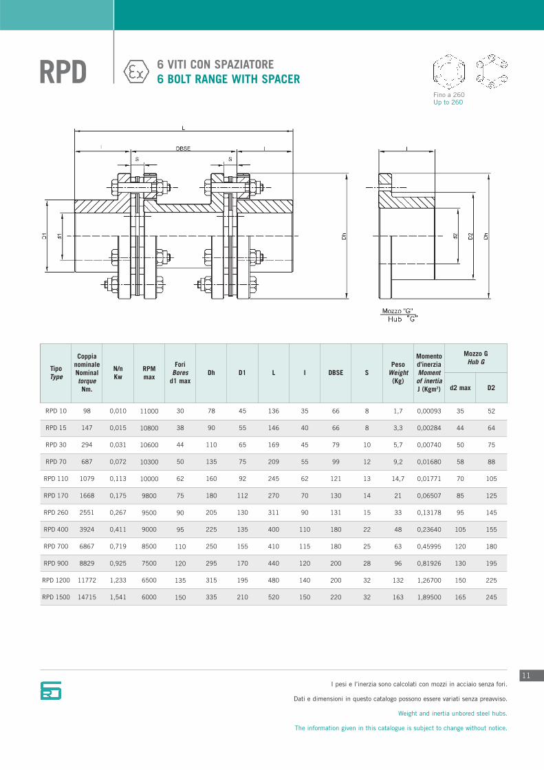
6 VITI CON SPAZIATORE6 BOLT RANGE WITH SPACERRPD
11
TipoType
CoppianominaleNominaltorqueNm.
N/nKw
RPMmax
ForiBores
d1 maxDh D1 L I DBSE S
PesoWeight
(Kg)
Momentod’inerziaMomentof inertiaJ (Kgm2) d2 max D2
RPD 10
RPD 15
RPD 30
RPD 70
RPD 110
RPD 170
RPD 260
RPD 400
RPD 700
RPD 900
RPD 1200
RPD 1500
98
147
294
687
1079
1668
2551
3924
6867
8829
11772
14715
0,010
0,015
0,031
0,072
0,113
0,175
0,267
0,411
0,719
0,925
1,233
1,541
11000
10800
10600
10300
10000
9800
9500
9000
8500
7500
6500
6000
30
38
44
50
62
75
90
95
110
120
135
150
78
90
110
135
160
180
205
225
250
295
315
335
45
55
65
75
92
112
130
135
155
170
195
210
136
146
169
209
245
270
311
400
410
440
480
520
35
40
45
55
62
70
90
110
115
120
140
150
66
66
79
99
121
130
131
180
180
200
200
220
8
8
10
12
13
14
15
22
25
28
32
32
1,7
3,3
5,7
9,2
14,7
21
33
48
63
96
132
163
0,00093
0,00284
0,00740
0,01680
0,01771
0,06507
0,13178
0,23640
0,45995
0,81926
1,26700
1,89500
35
44
50
58
70
85
95
105
120
130
150
165
52
64
75
88
105
125
145
155
180
195
225
245
Mozzo GHub G
Fino a 260Up to 260
I pesi e l’inerzia sono calcolati con mozzi in acciaio senza fori.
Dati e dimensioni in questo catalogo possono essere variati senza preavviso.
Weight and inertia unbored steel hubs.
The information given in this catalogue is subject to change without notice.
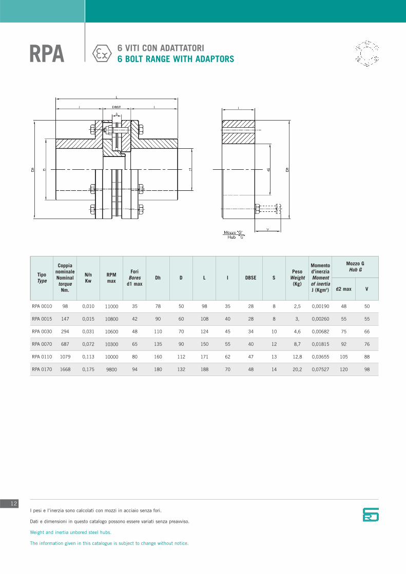
6 VITI CON ADATTATORI6 BOLT RANGE WITH ADAPTORSRPA
12
TipoType
CoppianominaleNominaltorqueNm.
N/nKw
RPMmax
ForiBores
d1 maxDh D L I DBSE S
PesoWeight
(Kg)
Momentod’inerziaMomentof inertiaJ (Kgm2) d2 max V
RPA 0010
RPA 0015
RPA 0030
RPA 0070
RPA 0110
RPA 0170
98
147
294
687
1079
1668
0,010
0,015
0,031
0,072
0,113
0,175
11000
10800
10600
10300
10000
9800
35
42
48
65
80
94
78
90
110
135
160
180
50
60
70
90
112
132
98
108
124
150
171
188
35
40
45
55
62
70
28
28
34
40
47
48
8
8
10
12
13
14
2,5
3,
4,6
8,7
12,8
20,2
0,00190
0,00260
0,00682
0,01815
0,03655
0,07527
48
55
75
92
105
120
50
55
66
76
88
98
Mozzo GHub G
I pesi e l’inerzia sono calcolati con mozzi in acciaio senza fori.
Dati e dimensioni in questo catalogo possono essere variati senza preavviso.
Weight and inertia unbored steel hubs.
The information given in this catalogue is subject to change without notice.

RSP
13
TipoType
CoppianominaleNominaltorqueNm.
N/nKw
RPMmax
ForiBores
d1 maxDh D L I DBSE S
PesoWeight
(Kg)
Momentod’inerziaMomentof inertiaJ (Kgm2) d2 max V
RSP 0010
RSP 0015
RSP 0030
RSP 0070
RSP 0110
RSP 0170
RSP 0260
RSP 0400
RSP 0700
RSP 0900
RSP 1200
RSP 1500
98
147
294
687
1079
1668
2551
3924
6867
8829
11772
14715
0,010
0,015
0,031
0,072
0,113
0,175
0,267
0,411
0,719
0,925
1,233
1,541
11000
10800
10600
10300
10000
9800
9500
9000
8500
7500
6500
6000
35
42
48
65
80
94
110
118
125
140
155
170
78
90
110
135
160
180
205
225
250
295
315
335
50
60
70
90
112
132
155
165
175
198
225
240
136
146
169
209
245
270
311
400
410
440
480
520
35
40
45
55
62
70
90
110
115
120
140
150
66
66
79
99
121
130
131
180
180
200
200
220
8
8
10
12
13
14
15
22
25
28
32
32
2,9
4,3
7,2
13,7
23,1
31,3
49,3
68,5
85
117
152
179
0,00137
0,00375
0,01037
0,02697
0,06425
0,11137
0,22787
0,36500
0,68550
0,91890
1,71350
2,32300
48
55
75
92
105
120
-
-
-
-
-
-
50
55
66
76
88
98
-
-
-
-
-
-
Mozzo GHub G
Fino a 0260Up to 0260
I pesi e l’inerzia sono calcolati con mozzi in acciaio senza fori.
Dati e dimensioni in questo catalogo possono essere variati senza preavviso.
Weight and inertia unbored steel hubs.
The information given in this catalogue is subject to change without notice.
6 VITI CON SPAZIATORE E ADATTATORI6 BOLT RANGE WITH SPACER AND ADAPTORS

8 VITI SENZA SPAZIATORE8 BOLT RANGE WITHOUT SPACERRP
14
TipoType
CoppianominaleNominaltorqueNm.
N/nKw
RPMmax
ForiBoresd max
Dh D L I SPeso
Weight(Kg)
Momentod’inerziaMomentof inertiaJ (Kgm2)
19620
24525
34335
49050
63765
78480
98100
127530
156960
196200
245250
294300
2,054
2,568
3,595
5,136
6,677
8,218
10,272
13,354
16,436
20,545
25,681
30,817
5800
5500
5000
4500
4000
3900
3700
3400
3100
2900
2800
2600
135
155
175
190
205
220
245
275
310
325
360
400
320
350
385
425
455
475
525
570
640
665
720
825
190
218
250
270
290
310
350
390
465
470
520
595
332
354
397
417
442
482
502
546
586
610
630
678
150
160
180
190
200
220
230
250
270
280
290
310
32
34
37
37
42
42
42
46
46
50
50
58
97
128
159
210
260
331
445
575
698
795
882
993
0,7648
1,2245
1,9480
3,1110
4,4100
6,3660
10,0020
15,1260
22,3360
26,7880
30,5180
38,1700
RP 2000
RP 2500
RP 3500
RP 5000
RP 6500
RP 8000
RP 10000
RP 13000
RP 16000
RP 20000
RP 25000
RP 30000
I pesi e l’inerzia sono calcolati con mozzi in acciaio senza fori.
Dati e dimensioni in questo catalogo possono essere variati senza preavviso.
Weight and inertia unbored steel hubs.
The information given in this catalogue is subject to change without notice.

8 VITI CON SPAZIATORE8 BOLT RANGE WITH SPACERRPD
15
TipoType
CoppianominaleNominaltorqueNm.
N/nKw
RPMmax
ForiBoresd max
Dh D L I DBSE S
Momentod’inerziaMomentof inertiaJ (Kgm2)
PesoWeight
(Kg)
19620
24525
34335
49050
63765
78480
98100
127530
156960
196200
245250
294300
2,054
2,568
3,595
5,136
6,677
8,218
10,272
13,354
16,436
20,545
25,681
30,817
5800
5500
5000
4500
4000
3900
3700
3400
3100
2900
2800
2600
135
155
175
190
205
220
245
275
310
325
360
400
320
350
385
425
455
475
525
570
640
665
720
825
190
218
250
270
290
310
350
390
465
470
520
595
530
560
660
690
730
790
830
890
960
990
1020
1130
150
160
180
190
200
220
230
250
270
280
290
340
230
240
300
310
330
350
370
390
420
430
440
450
32
34
37
37
42
42
42
46
46
50
50
58
138
175
210
276
341
409
547
674
797
899
985
1131
1,2728
1,9740
3,0690
4,8640
6,9090
9,7940
14,9870
22,0520
31,1960
37,0640
42,1290
52,7790
RPD 2000
RPD 2500
RPD 3500
RPD 5000
RPD 6500
RPD 8000
RPD 10000
RPD 13000
RPD 16000
RPD 20000
RPD 25000
RPD 30000
I pesi e l’inerzia sono calcolati con mozzi in acciaio senza fori.
Dati e dimensioni in questo catalogo possono essere variati senza preavviso.
Weight and inertia unbored steel hubs.
The information given in this catalogue is subject to change without notice.

8 VITI CON SPAZIATORE E ADATTATORI8 BOLT RANGE WITH SPACER AND ADAPTORSRSP
16
TipoType
CoppianominaleNominaltorqueNm.
N/nKw
RPMmax
ForiBoresd max
Dh D L I DBSE S
Momentod’inerziaMomentof inertiaJ (Kgm2)
PesoWeight
(Kg)
19620
24525
34335
49050
63765
78480
98100
127530
156960
196200
245250
294300
2,054
2,568
3,595
5,136
6,677
8,218
10,272
13,354
16,436
20,545
25,681
30,817
5800
5500
5000
4500
4000
3900
3700
3400
3100
2900
2800
2600
160
180
190
205
230
260
285
315
360
375
405
440
320
350
385
425
455
475
525
570
640
665
720
825
225
245
270
290
325
360
400
440
505
520
575
660
530
560
660
690
730
790
830
890
960
990
1020
1130
150
160
180
190
200
220
230
250
270
280
290
340
230
240
300
310
330
350
370
390
420
430
440
450
32
34
37
37
42
42
42
46
46
50
50
58
158
211
261
342
422
493
639
786
978
1093
1192
1489
1,6560
2,5600
4,0300
6,4230
8,9510
12,7330
18,9800
27,9890
39,9540
47,3400
53,7400
71,3610
RSP 2000
RSP 2500
RSP 3500
RSP 5000
RSP 6500
RSP 8000
RSP 10000
RSP 13000
RSP 16000
RSP 20000
RSP 25000
RSP 30000
I pesi e l’inerzia sono calcolati con mozzi in acciaio senza fori.
Dati e dimensioni in questo catalogo possono essere variati senza preavviso.
Weight and inertia unbored steel hubs.
The information given in this catalogue is subject to change without notice.

ESECUZIONI SPECIALISPECIAL EXECUTIONS
17
Esecuzione con allunga in acciaio, adatta a tutte le applicazioni.Si progettano soluzioni a richiesta anche realizzate in acciaio inos-sidabile AISI 304, AISI 316. Tale forma costruttiva è realizzabile conla serie RPD, RSP e RSL
Steel spacer execution, fitting to any applications. Requested solutionare provided even in stainless steel AISI 304, AISI 316. Such an exe-cution may be achieved with the RPD, RSP and RSL series.
Esecuzione con allunga in Fibra di Carbonio, particolarmente adattaalle applicazioni in torri di ventilazione, si progettano soluzioni a richi-esta anche realizzate in acciaio inossidabile AISI 304, AISI 316. Taleforma costruttiva è realizzabile con la serie RPD, RSP e RSL.
Steel spacer in carbon fibres execution, especially suitable to appli-cations in cooling towers. Requested applications are provided instainless steel AISI 304, AISI 316, too. Such an execution may beachieved with the RPD, RSP and RSL series.
Esecuzione con flangia di accoppiamento. Tale forma costruttivaè realizzabile con la serie RPD e RSP.
Coupling flange execution. Such an execution is achieved with RPDand RSP series.
Esecuzione compatta, realizzata con un distanziale fresato consentail montaggio di due elementi flessibili limitando la distanza tra leteste degli alberi. Tale forma costruttiva è realizzabile con la serieRPD e RSP.
Compact execution with a milled spacer allowing the assembly of twoflexible elements limiting the distance between the shaft-ends. Suchan application is achieved with RPD and RSP series.
Esecuzione supportante, adottabile per i montaggi verticali quando ilpeso dello spaziatore potrebbe danneggiare gli elementi flessibili.Tale forma costruttiva è realizzabile con la serie RPD e RSP.
Supporting execution, fitting to vertical assemblies whereas thespacer’s weight may damage the flexible elements. Such an executionis achieved with RPD and RSP series.
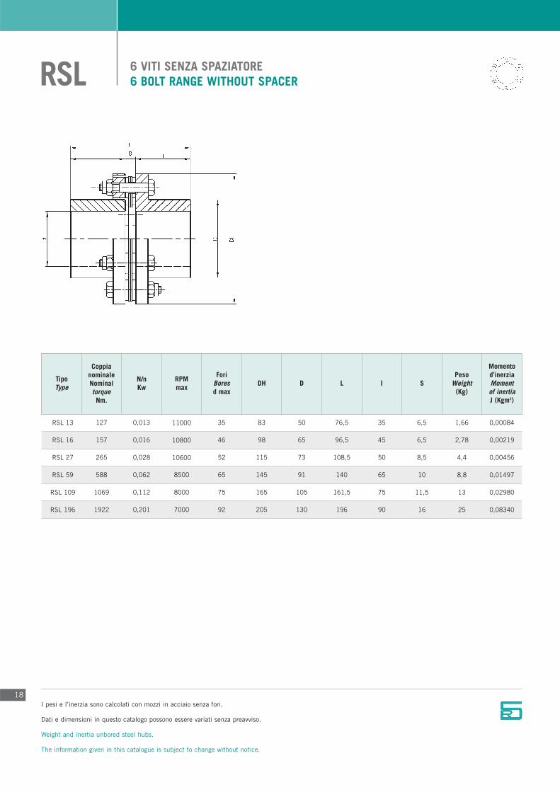
6 VITI SENZA SPAZIATORE 6 BOLT RANGE WITHOUT SPACERRSL
18
TipoType
CoppianominaleNominaltorqueNm.
N/nKw
RPMmax
ForiBoresd max
DH D L I SPeso
Weight(Kg)
Momentod’inerziaMomentof inertiaJ (Kgm2)
127
157
265
588
1069
1922
0,013
0,016
0,028
0,062
0,112
0,201
11000
10800
10600
8500
8000
7000
35
46
52
65
75
92
83
98
115
145
165
205
50
65
73
91
105
130
76,5
96,5
108,5
140
161,5
196
35
45
50
65
75
90
6,5
6,5
8,5
10
11,5
16
1,66
2,78
4,4
8,8
13
25
0,00084
0,00219
0,00456
0,01497
0,02980
0,08340
RSL 13
RSL 16
RSL 27
RSL 59
RSL 109
RSL 196
I pesi e l’inerzia sono calcolati con mozzi in acciaio senza fori.
Dati e dimensioni in questo catalogo possono essere variati senza preavviso.
Weight and inertia unbored steel hubs.
The information given in this catalogue is subject to change without notice.

6 VITI CON SPAZIATORE6 BOLT RANGE WITH SPACERRSLD
19
TipoType
CoppianominaleNominaltorqueNm.
N/nKw
RPMmax
ForiBoresd max
Dh D L I DBSE S
Momentod’inerziaMomentof inertiaJ (Kgm2)
PesoWeight
(Kg)
127
157
265
588
1069
1922
0,013
0,016
0,028
0,062
0,122
0,201
11000
10800
10600
8500
8000
7000
35
46
52
65
75
92
83
98
115
145
165
205
50
65
73
91
105
130
125
145
170
220
260
310
35
45
50
65
75
90
55
55
70
90
110
130
6,5
6,5
8,5
10
11,5
16
2,1
4,3
7,5
11,7
17
35
0,00118
0,00306
0,00704
0,02336
0,04606
0,13280
RSLD 13
RSLD 16
RSLD 27
RSLD 59
RSLD 109
RSLD 196
I pesi e l’inerzia sono calcolati con mozzi in acciaio senza fori.
Dati e dimensioni in questo catalogo possono essere variati senza preavviso.
Weight and inertia unbored steel hubs.
The information given in this catalogue is subject to change without notice.

6 VITI CON SPAZIATORE ED UN MOZZO INTERNO6 BOLT RANGE WITH SPACER AND AN INTERNAL HUBRSLE
TipoType
N/nKw
d1 max d2 max
ForiBores
Dh D1RPMmax
D2 L I l1 S
CoppianominaleNominaltorqueNm.
DBSEPeso
Weight(Kg)
Momentod’inerziaMomentof inertiaJ (Kgm2)
20
RSLE 13
RSLE 16
RSLE 27
RSLE 59
RSLE 109
RSLE 196
127
157
265
588
1069
1922
0,013
0,016
0,028
0,062
0,112
0,201
11000
10800
10600
8500
8000
7000
30
40
45
55
65
80
35
46
52
65
75
92
83
98
115
145
165
205
42
56
63
77
91
112
50
65
73
91
105
130
98
108
129
167
199
237
35
45
50
65
75
90
35
40
45
55
65
80
28
23
34
47
59
67
6,5
6,5
8,5
10
11,5
16
1,95
4,2
7,1
10,9
15,5
32,5
0,00112
0,00290
0,00668
0,02248
0,04375
0,12610
I pesi e l’inerzia sono calcolati con mozzi in acciaio senza fori.
Dati e dimensioni in questo catalogo possono essere variati senza preavviso.
Weight and inertia unbored steel hubs.
The information given in this catalogue is subject to change without notice.
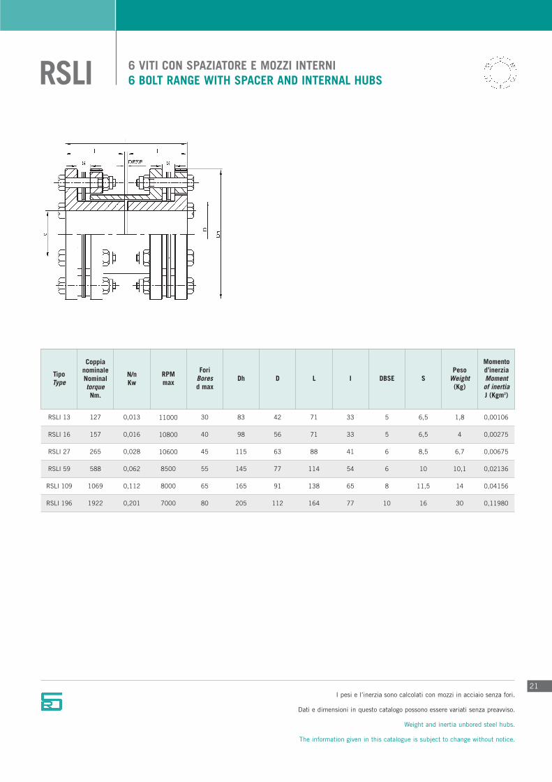
6 VITI CON SPAZIATORE E MOZZI INTERNI6 BOLT RANGE WITH SPACER AND INTERNAL HUBSRSLI
21
TipoType
CoppianominaleNominaltorqueNm.
N/nKw
RPMmax
ForiBoresd max
Dh D L I DBSE S
Momentod’inerziaMomentof inertiaJ (Kgm2)
PesoWeight
(Kg)
127
157
265
588
1069
1922
0,013
0,016
0,028
0,062
0,112
0,201
11000
10800
10600
8500
8000
7000
30
40
45
55
65
80
83
98
115
145
165
205
42
56
63
77
91
112
71
71
88
114
138
164
33
33
41
54
65
77
5
5
6
6
8
10
6,5
6,5
8,5
10
11,5
16
1,8
4
6,7
10,1
14
30
0,00106
0,00275
0,00675
0,02136
0,04156
0,11980
RSLI 13
RSLI 16
RSLI 27
RSLI 59
RSLI 109
RSLI 196
I pesi e l’inerzia sono calcolati con mozzi in acciaio senza fori.
Dati e dimensioni in questo catalogo possono essere variati senza preavviso.
Weight and inertia unbored steel hubs.
The information given in this catalogue is subject to change without notice.
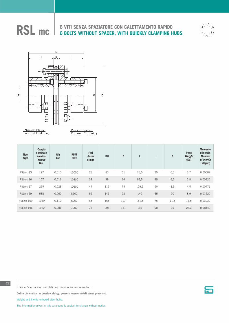
6 VITI SENZA SPAZIATORE CON CALETTAMENTO RAPIDO6 BOLTS WITHOUT SPACER, WITH QUICKLY CLAMPING HUBSRSL mc
22
TipoType
CoppianominaleNominaltorqueNm.
N/nKw
RPMmax
ForiBoresd max
DH D L I SPeso
Weight(Kg)
Momentod’inerziaMomentof inertiaJ (Kgm2)
127
157
265
588
1069
1922
0,013
0,016
0,028
0,062
0,112
0,201
11000
10800
10600
8500
8000
7000
28
38
44
55
65
75
83
98
115
145
165
205
51
66
75
92
107
131
76,5
96,5
108,5
140
161,5
196
35
45
50
65
75
90
6,5
6,5
8,5
10
11,5
16
1,7
1,8
4,5
8,9
13,5
23,3
0,00087
0,00225
0,00476
0,01520
0,03030
0,08440
RSLmc 13
RSLmc 16
RSLmc 27
RSLmc 59
RSLmc 109
RSLmc 196
I pesi e l’inerzia sono calcolati con mozzi in acciaio senza fori.
Dati e dimensioni in questo catalogo possono essere variati senza preavviso.
Weight and inertia unbored steel hubs.
The information given in this catalogue is subject to change without notice.
23
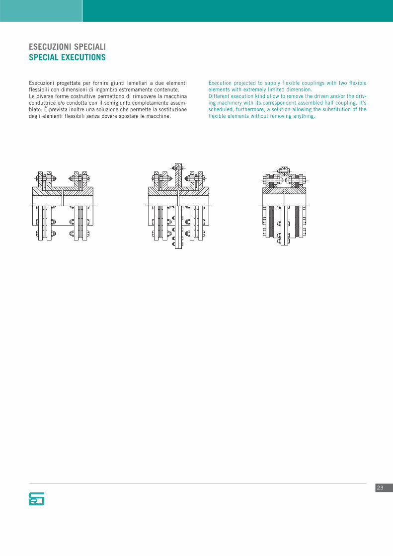
ESECUZIONI SPECIALISPECIAL EXECUTIONS
Esecuzioni progettate per fornire giunti lamellari a due elementiflessibili con dimensioni di ingombro estremamente contenute.Le diverse forme costruttive permettono di rimuovere la macchinaconduttrice e/o condotta con il semigiunto completamente assem-blato. È prevista inoltre una soluzione che permette la sostituzionedegli elementi flessibili senza dovere spostare le macchine.
Execution projected to supply flexible couplings with two flexibleelements with extremely limited dimension.Different execution kind allow to remove the driven and/or the driv-ing machinery with its correspondent assembled half coupling. It’sscheduled, furthermore, a solution allowing the substitution of theflexible elements without removing anything.

INDICAZIONI GENERALI PER IL MONTAGGIO E L’ ALLINEAMENTO
24
Allineamenti iniziali precisi consentiranno variazioni di condizionidurante l’esercizio e quindi una lunga durata dei giunti.I mozzi devono essere calettati in modo che la testa degli assi vengaa trovarsi a filo delle facce delle flangie: la distanza tra le due flangiesarà quindi pari alla quota “S” per i giunti con solo un elementoflessibile, pari alla quota dello spaziatore completo “DBSE” nei giun-ti con due elementi flessibili.Una volta posizionate le macchine si procede a un allineamentoiniziale posizionando una riga sulle flangie dei mozzi ogni 90° (fig. 1)avendo così un primo allineamento sia verticale che orizzontale, suc-cessivamente procedere al controllo dell’allineamento assiale chedeve rientrare nei limiti qui sotto riportati:
Allineamento assialeGiunti con un elemento flessibile:Giunti a 4 Viti: -0/+0,5 della quota “S”Giunti a 6 Viti: -0/+0,4 della quota “S”Giunti a 8 Viti: -0/+0,25 della quota “S”
Giunti con due elementi flessibili:Giunti a 4 Viti: -0/+1 della quota “DBSE”Giunti a 6 Viti: -0/+0,8 della quota “DBSE”Giunti a 8 Viti: -0/+0,5 della quota “DBSE”
Allineamento angolare e radiale Procedere a questo punto con il montaggio dell’elemento flessibile,o degli eventuali elementi flessibili completi di spaziatore serrandoi dadi con i rispettivi bulloni.
Rilevare con un comparatore (fig. 2) la quota minima tra le faccedelle rispettive flangie, azzerarlo, rilevare la quota massima,dividere tale dato per il diametro della flangia in mm., il risultatosarà un valore in mm. che non dovrà superare i parametri di segui-to riportati:
Giunti a 4 Viti: 0.0040 mm. per mm. del diametro della flangiaGiunti a 6 Viti: 0.0030 mm. per mm. del diametro della flangiaGiunti a 8 Viti: 0.0020 mm. per mm. del diametro della flangia
O in alternativa, rilevare accuratamente con un calibro centesimalela distanza tra le superfici interne delle flangie (fig.3) ricavando laquota massima A e la quota minima B. Con il diametro della flan-gia D si ha:
disassamento massimo in mm, che deve rispettarei valori sopraindicati.
Per i giunti con due elementi flessibili ripetere l’operazione daambo le parti del giunto, o procedere al bloccaggio di un lato delgiunto, inserendo tra le flangie degli spessori rettificati pari allaquota “S”, fissare la parte con dei morsetti irrigidendo completa-mente un lato. A questo punto procedere, dal lato opposto, al con-trollo come sopra indicato calcolando che i valori di confrontosaranno doppi. Tali procedimenti consentono un controllo del disassamento siaangolare che parallelo fornendo solo comunque direttive di massi-ma e non sono da intendersi come norme di montaggio e/omanutenzione dei giunti.
A – BD
=
fig. 1 fig. 2 fig. 3

25
GENERAL GUIDE-LINES FOR ASSEMBLY AND ALIGNEMENT
Precise alignments, when assembling the coupling, will allowchanges of conditions during operation and thus ensure a long,trouble free, working life to the coupling itself.Parallel bored hubs should be fitted so that the shaft end is flushedwith the flanges’ faces: the distance between the flanges willmatch with the “S” value for one-flexible element couplings, andwith the complete “DBSE” value with two-flexible elements cou-plings. Once the machines are ready to start, it is necessary tobegin with a first alignment placing a line on the hubs’ flangesevery 90°. (fig.1). Doing so both a vertical and an horizontal ali-gnment is approximately obtained. After that it is suggested tocheck the axial alignment which must be within the limits herequoted.
Axial alignmentOne flexible-element couplings:4 Bolt couplings: -0\+0.5 of “S” value6 Bolt couplings: -0\+0.4 of “S” value 8 Bolt couplings: -0\+0.25 of “S” value
Two-flexible elements couplings:4 Bolt couplings: -0\+1 of “DBSE” value6 Bolt couplings: -0\+0.8 of “DBSE” value8 Bolt couplings: -0\+0.5 of “DBSE” value
Radial and angular alignmentAt this point it is important to carry on the flexible elementassembly, or more flexible elements endowed with “DBSE”,
tightening the nuts to their correspondent bolts.Use a dial indicator in order to achieve the minimum distancebetween the flanges’ faces, then reset it, note the maximumdistance, divide such data by the flange’s diameter, the resultmustn’t exceed the limits here quoted:
4 Bolt couplings: 0.0040 mm. / mm. of the flange’s diameter6 Bolt couplings: 0.0030 mm. / mm. of the flange’s diameter8 Bolt couplings: 0.0020 mm. / mm. of the flange’s diameter
Alternatively, carefully note using a centesimal gauge thedistance between the flanges’ internal surfaces (fig.3) obtainingthe maximum distance A and the minimum distance B. Withthe D flange’s diameter:
Maximum Misalignment in mm, which must be within the up-quoted values.
When working with two-elements couplings repeat the operationon both coupling’s sides, or, alternatively, block one side of thecoupling inserting a grinding gauge equal to “S” value, tightenthat side with terminals completely stiffening one side. Now proceed, as above indicated, checking the other side of thecoupling, noting that the values shall be double.Such procedures allow both an angular and a parallel misali-gnment’s checks, but they mustn’t be regarded as assembly ormaintenance instructions whatsoever.
A – BD
=
fig. 1 fig. 2 fig. 3

MODULO RICHIESTA INFORMAZIONI DA INVIARE VIA FAXINFORMATIONS REQUEST FORM FOR FAX
Dimensionamento giunto - Data for the coupling choice
Macchina conduttrice :Conductor machine
Potenza Kw :Power
Velocità giri/1’ :Speed
Diametro albero :Shaft diameter
Macchina condotta :Conducted machine
Diametro albero :Shaft diameter
Distanza tra gli alberi delle macchine :Distance between shafts of machines
Montaggio :Assembling
Lavorazione mozzi :Hubs
Tipo avviamento :Type of start
Lunghezza albero mm.:Lenght shaft
Lunghezza albero mm.:Lenght shaft
Orizzontale:Horizontal
Verticale:Vertical
Note - Notes

Giunti elastici tipo “ULISSE”.Elastic couplings type “ULISSE”.
Giunti elastici tipo “GFE”.Elastic couplings type “GFE”.
Giunti a denti tipo “ZEUS”.Teeth couplings type “ZEUS”.
Giunti elastici tipo “E”.Elastic couplings type “E”.
Giunti elastici tipo “A” “B”.Elastic couplings type “A” “B”.
Spaziatore in fibra di carbonio tipo “LS”.Carbon fibre spacer type “LS”.
Giunti a denti autolubrificanti tipo “GD”.Self lubricating gear couplings type “GD”.
Giunti rigidi tipo “GRM”.Rigid couplings type “GRM”.
ALTRI GIUNTI IN PRODUZIONEOTHERS COUPLINGS IN PRODUCTION
Sede legale:
Via Sforza, 4
20060 Liscate (Mi)
Sede produttiva:
Via Ugo La Malfa, 25
20066 Melzo (Mi)
Tel. +39 02.95735269
Fax. +39 02.95735270
www.ru-steel.it
ww
w.c
rear
tcom
.itEDIZIONE
2007


![Tester della qualità di dishi e ruote on gamo lamellari - SMAsma-solutions.it/download/pdf/IT SMA-ECO-test.pdf · S.M.A. Srl Sede legale: Piazza Veronesi, 7 - 46019 Viadana [MN]](https://static.fdocuments.in/doc/165x107/5b5233e37f8b9ae22c8d072a/tester-della-qualita-di-dishi-e-ruote-on-gamo-lamellari-smasma-sma-eco-testpdf.jpg)