GIRTH GEARS AND PINIONS OVERVIEW Gears & Pinions Tubular mills and rotary kiln operations are the...
14
GIRTH GEARS AND PINIONS OVERVIEW
Transcript of GIRTH GEARS AND PINIONS OVERVIEW Gears & Pinions Tubular mills and rotary kiln operations are the...

GIRTH GEARS AND PINIONS OVERVIEW

Girth Gears & Pinions
Tubular mills and rotary kiln operations are the life support system for the processing industries, and necessitates reliable and uninterrupted operations.

Governing Specifications
The specifications of girth gears and pinions are governed by AGMA 6014/6114-A06, published in 2006 (this is the latest revision of AGMA 6004, which was published in 1988) The AGMA standard specifies the following components which are critical for the selection and life of girth gears and pinions.
Service Factors by application
Application Surface Durability Csf Strength Ksf
Ball Mills 1.50 - 1.75 2.25
Rod Mills 1.65 - 1.75 2.50
Kilns 1.00 - 1.40 1.75 – 2.25
Dryers & Coolers
1.00 - 1.40 1.50 – 2.25
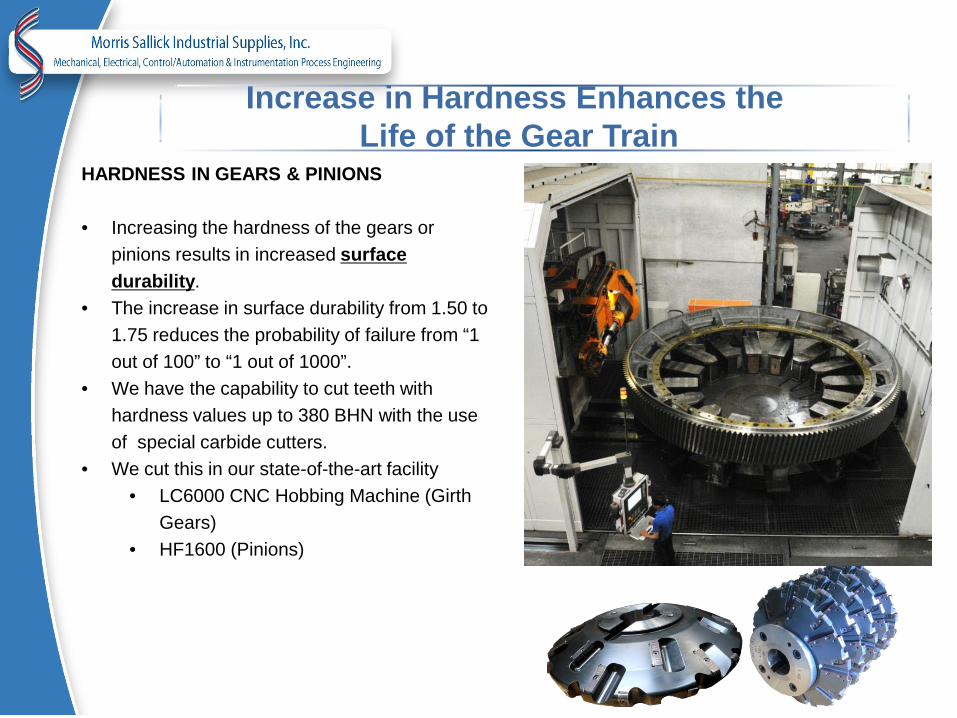
Increase in Hardness Enhances the Life of the Gear Train
HARDNESS IN GEARS & PINIONS • Increasing the hardness of the gears or
pinions results in increased surface durability.
• The increase in surface durability from 1.50 to 1.75 reduces the probability of failure from “1 out of 100” to “1 out of 1000”.
• We have the capability to cut teeth with hardness values up to 380 BHN with the use of special carbide cutters.
• We cut this in our state-of-the-art facility • LC6000 CNC Hobbing Machine (Girth
Gears) • HF1600 (Pinions)

Enhanced Pinion Hardness Requires Proper Material Selection
MATERIAL SELECTION FOR PINIONS
• Materials with higher alloys have increased core hardness, and thus proper selection of materials for a mill pinions are very important.
• Depending upon the ruling sections of a specific pinion, we offer correct grades of material to achieve higher core hardness.
Sr. No. Material Surface Hardness Ruling Section
1 Forged (AISI 4340 / En 24) 248-280 BHN 150 mm
2 EN 26 269-331 BHN 250 mm
3 EN 30B 341-401 BHN 300 mm

Higher Surface Hardness on Pinion Teeth Enhances the Life of the Gear Train
SURFACE HARDNESS OPTIONS FOR PINIONS Generally, the mill pinions undergo 5 times higher wear then the gears. • Higher surface hardness increases the durability service factor (Csf) which enables the pinion to
withstand the high wear. • We have capability to supply pinions with surface hardness up to 55 -62 HRC. • The higher surface hardness is achieved by either induction hardening or case carburizing.
Sr. No. Material Heat Treatment Surface
Hardness
1 AISI 4340 / En 24 Induction 52-55 HRC
2 EN 26 Induction 52-55 HRC
3 EN 30B Induction 52-55 HRC
4 18CrNiMo7-6 Case Carburizing 52-62 HRC

Myth

Gear Accuracy and Surface Finish Better AGMA quality levels result in higher durability and strength factors.
• We manufacture girth gears confirming to AGMA 10/DIN 8 and pinions confirming to AGMA 12/DIN 6.
• The quality levels of our girth gears and pinions are certified by test reports.
• We provide surface finishes finer than 1.6µ, which generates better rolling motions and improved teeth contact, providing better load distribution.
COMPARISION OF QUALITY LEVELS ON DURABILITY AND STRENGTH
AGMA 2000 Quality Levels
Available Service Factors Surface Durability Strength
7 1.11 2.52 8 1.27 2.88 9 1.35 3.06
10 1.43 3.24

Load Distribution Factors
Load distribution factors are one of the parameters that directly affects the life of the girth gears and pinions. • The mill may have inherent issues such as:
o Misalignment o Deflection and bending of teeth o Torsional twisting and bending of the pinion shaft
• These issues can cause an uneven load distribution, creating adverse effects on the gear set life.
• Higher quality levels of gears and pinions will ensure
that some of these factors are compensated for. • We strongly recommended that our customers consider
quality levels of AGMA 8 while designing the girth gears, but manufacture the gears with a level of AGMA 10, to compensate for the above factors.

Mill Pinions
The right combination of girth gears and pinions are very important for the overall performance of the mill.

Recommendations
The following table can serve as guideline for the right combination of the girth gears and their matching pinions.
Gear Pinion
Remarks Material
Surface Durability (Csf)
Strength (Ksf) Material
Surface Durability
(Csf)
Strength (Ksf)
SG Iron (GGG 70) 1.25 2.56 Forged (AISI 4340 / En 24) 1.86 2.78 Not in line with AGMA Standards
Cast Steel (CS 700 IS 2644) 1.38 3.25 EN 26 2.43 3.12 Not in line with AGMA Standards
Cast Steel (CS 840 IS 2644) 1.68 3.30 EN 26 2.43 3.12
Within AGMA Standards, but lower reliability
Forged (AISI 4140/ En 19) 2.07 3.36 EN 30B 3.08 3.45 Meets AGMA Standards
Forged (AISI 4340 / En 24) 2.70 3.77 EN 30B 3.08 3.45 Best Performance
Forged (AISI 4340 / En 24) 2.70 3.77 18CrNiMo7-6 5.96 4.42 Highest Performance

Why Forged Fabricated Gears?
› Castings have inherent internal defects such as blow holes, shrinkages,
and inclusions, which may result in premature failure of the gears.
› Forgings have practically zero internal defects.
› Forgings have a finer grain structure compared to castings, which
provides higher impact and elongation properties, giving better reliability
to the end user.
› The higher impact and elongation provides the ability to achieve higher
hardness levels in the forgings.
› Forged gears may result in higher initial costs as compared to cast
gears.

Equivalent Specifications
Equivalent grades of various material used for girth gears and pinions are given below.
IS BS DIN AISI / SAE IS:1865 EN 1563 GGG 70 ASTM A536
CS 700 IS 2644 BT1 as per BS:3100 GS25CrMo4-Q.T. ASTM A148
CS 840 IS 2644 BT2 as per BS:3100 GS34CrMo4 Q.T. ASTM A148
CS1030 IS 2644 BT3 as per BS:3100 GS42CrMo4 Q.T. N/A
40Cr1Mo28 En 19 (709M40) 42CrMo4 AISI 4140
40Ni2Cr1Mo28 En 24(817m40) 34CrNiMo6 AISI 4340
N/A EN 26 (826M40) N/A N/A
30Ni4Cr1Mo EN 30B(835m30) 36NiCrMo16 N/A
16NiCr2Mo20 N/A 18CrNiMo7-6 N/A

Production Range
Description Product Range
AGMA / DIN Quality Max. OD Max. Module (Dp)
External Gears Spur Gears & Pinions 6,400 50 AGMA 10 / DIN 8 Helical Gears & Pinions 6,400 50 AGMA 10 / DIN 8 Double Helical Gears 4,500 30 AGMA 10 / DIN 8 Pinion shaft & Splines 1,650 30 AGMA 10 / DIN 8 Spur Gear 6,000 (PCD) 30 Face width 500 mm AGMA 10/ DIN 8 Helical Gear 6,000 (PCD) 30 (<= 250 helix angle) face width 500 mm AGMA 10 / DIN 8 External Gear Grinding* Spur gears 6,000 50 AGMA 15 / DIN 3 Helical gears 6,000 50 AGMA 15 / DIN 3 Gear Inspection Lead 6,000 50 Profile 6,000 50 Pitch 6,000 50 Cumulative Pitch 6,000 50 Pitch line run out 6,000 50