GigE Vision cameras and network performance · Abstract This article discusses the most important...
18
GigE Vision cameras and network performance by Jan Becvar - Leutron Vision http://www.leutron.com © 2009 Leutron Vision AG 1
Transcript of GigE Vision cameras and network performance · Abstract This article discusses the most important...
GigE Vision cameras and network performance
by Jan Becvar - Leutron Vision
http://www.leutron.com
© 2009Leutron Vision AG 1
Table of content
Abstract........................................................................................................2Basic terms...................................................................................................2From trigger to the processed image............................................................4Usual system configurations.........................................................................4GigE Vision protocol and the OSI model.......................................................5Packet size, jumbo frames.............................................................................6Flow control (packet delay, image frame delay)............................................8Host PC resources.......................................................................................10Network card selection and configuration..................................................11Switch selection and configuration.............................................................12Cabling.......................................................................................................13Filter drivers................................................................................................14Input/output interface................................................................................15PicSight RTF and Smart models..................................................................16Using 100Mb/s Ethernet.............................................................................16Summary....................................................................................................17
© 2009Leutron Vision AG 2
Abstract
This article discusses the most important aspects of the use of PicSight GigE Vision cameras (PicSight-GigE and PicSight-Smart) from perspective of the network performance. The PicSight cameras are fully GigE Vision and GenICam compatible and can thus be used either with Leutron Vision SDK or with any other GigE Vision & GenICam compatible software package. Some of the options discussed below might differ slightly between individual software packages.
Gigabit Ethernet based cameras offer some obvious advantages over competing transport layer technologies:
• Cost effective solution based on off the shelf components.• Long distance connections: 100m per segment, total length practically unlimited.• Flexible network configurations, many cameras in a system.• High performance, good scalability (via multiple network cards).• Excellent interoperability and vendor independence thanks to the GigE Vision and
GenICam standards.
On the other hand, potential users are sometimes asking about the CPU load associated with acquisition from GigE cameras, about the system latency (and especially its predictability) and reliability. We'll show that GigE Vision systems demonstrate great performance numbers. With basic understanding of the networking technology and with elementary care for the important factors, the mentioned possible negative effects can be easily eliminated. The small required effort quickly pays off through the advantages that established networking technology offers. This text covers all the important aspects of the network performance that might need to be considered while building the system.
Basic terms
Link speed - describes the type of the Ethernet used to connect the camera(s). The PicSight GigE Vision cameras are primarily designed for Gigabit Ethernet (1Gb/s, 1000BASE-T). However, they can also be used in the Fast Ethernet (100Mb/s, 100BASE-TX) environments, if the limited performance of the Fast Ethernet satisfies the application needs.Bandwidth - defines the maximum theoretical capacity of the link, ie. how much data the medium can transfer in a time unit. Bandwidth is defined by the link speed. For Gigabit Ethernet it is 1Gb/s ie. 119.2MB/s (119.2 megabyte per second). If the conversion 1Gb/s=119.2MB/s looks weird to you, recall that by convention 1MB=1024*1024B, while the Gb/s unit for the link speed, based on the data signaling rate, is a decimal unit, ie. 1Gb/s=1E9b/s). It is important to understand that for different reasons (discussed in this article) the real amount of useful data transferred over the link is always lower than the theoretical bandwidth.Overhead - can be described as part of the bandwidth which cannot be used to transfer useful data. We need to consider especially two types of overhead. Part of the bandwidth is consumed for purposes of the protocols carrying the useful image data (headers/footers of individual packets, control packets, etc.). These data are so called "protocol overhead". Additional bandwidth is wasted whenever the link is inactive (collision, waiting until camera has more data ready or until the host can process the data available) or when additional data need to be sent over the link (lost packets, packet resends, errors). This can be called "processing overhead".Throughput - is the real amount of useful data (in our case usually image data) that can
© 2009Leutron Vision AG 3

be transferred in a time unit. The real throughput can be affected by many factors (such as network and system configuration, host loading, connected cameras) and depending on the conditions, it can vary over time. We'll discuss the important factors and ways to optimize them in this article.Latency - is the time between starting an action and finishing it. With GigE Vision cameras we can consider the basic network related latency (time elapsed between acquiring the image by the camera until it's delivered in the target buffer, ready for processing). In the more general case we can consider the full task latency (time elapsed between triggering/requesting the image and finishing its processing and performing resulting actions). Although the network related latency is usually low enough for most applications, due to the Ethernet nature, it cannot be fully deterministic, and latency sensitive applications need to keep an eye on corresponding issues. Moreover, throughput and latency frequently work against each other and attempts to optimize throughput can negatively affect latency.Jitter – is, in general, an unwanted variation of given timing characteristic. To achieve real-time behavior, the jitters in the system should be low, and especially predictable. Ethernet communication is not fully deterministic due to various reasons discussed below and therefore the timings are subject to a jitter. We'll discuss the jitter associated with individual measured latencies and provide hints how to minimize it.Collision domain - in Ethernet terminology, a network segment where packets sent from various devices might collide. In a more general case, collision domain can stand for any resource for which individual system components or processes compete. It might be the host CPU shared between packet retrieval and dissecting code and between the actual application processing. It might be other PC resources, such as memory or PCI bus. It might be a switch being shared by multiple connected cameras, possibly sending data at the same time. It can be a network shared for image acquisition and other purposes. Any of these collision domains can have significant influence on system throughput and latency.
From trigger to the processed image
To understand the performance related issues, it's useful to know the operations executed during the image acquisition:
• If working in triggered mode, the operation starts with the image trigger, which can be issued either through the camera's digital I/O interface or by means of a software command (applying the "TriggerSoftware" GenICam command). When using the software trigger, the trigger command travels to the camera through the network and is thus subject to additional latency.
• The camera's sensor acquires the image, camera starts reading it out into the on-camera frame buffer.
• When the amount of read out data reaches a certain limit, the camera sends the data out in a packet burst, by default at full speed. When the limit is reached again, another packet burst is sent, until the entire image is sent to the network.
• The packets are traveling across the network to the host. When crossing a switch, they might get temporarily blocked if the switch is processing packets from another camera(s). If the switch cannot cope with the incoming data, packets might get dropped.
• The packets reach the host's network card which collects them and signals new data through interrupts. The data gets processed by a standard operating system network stack or by a dedicated (filter) driver and delivered to the target buffer. If the host load is too high and cannot cope with the incoming data rate, the packets might again get dropped.
© 2009Leutron Vision AG 4
• The complete image is processed and the result possibly signaled to the external devices. When controlling external devices through the camera's digital I/O, the I/O status is again transferred across the network and thus subject to additional latency. In most cases this additional latency is insignificant compared to the complete process, however, it should be taken into consideration for latency and real-time critical applications.
Usual system configurations
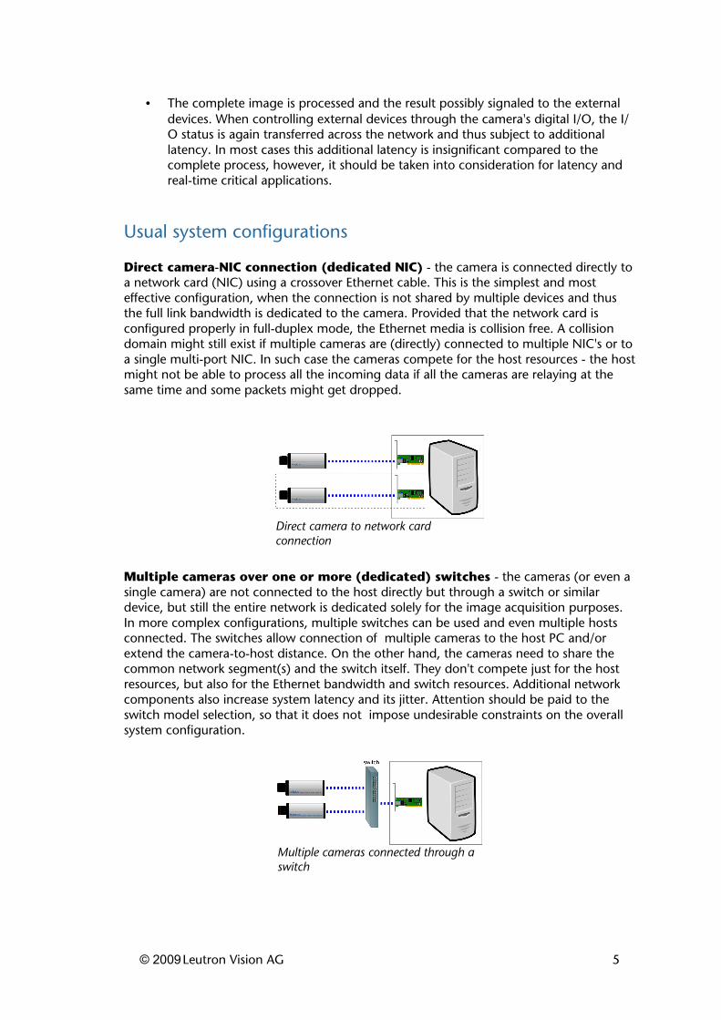
Direct camera-NIC connection (dedicated NIC) - the camera is connected directly to a network card (NIC) using a crossover Ethernet cable. This is the simplest and most effective configuration, when the connection is not shared by multiple devices and thus the full link bandwidth is dedicated to the camera. Provided that the network card is configured properly in full-duplex mode, the Ethernet media is collision free. A collision domain might still exist if multiple cameras are (directly) connected to multiple NIC's or to a single multi-port NIC. In such case the cameras compete for the host resources - the host might not be able to process all the incoming data if all the cameras are relaying at the same time and some packets might get dropped.
Multiple cameras over one or more (dedicated) switches - the cameras (or even a single camera) are not connected to the host directly but through a switch or similar device, but still the entire network is dedicated solely for the image acquisition purposes. In more complex configurations, multiple switches can be used and even multiple hosts connected. The switches allow connection of multiple cameras to the host PC and/or extend the camera-to-host distance. On the other hand, the cameras need to share the common network segment(s) and the switch itself. They don't compete just for the host resources, but also for the Ethernet bandwidth and switch resources. Additional network components also increase system latency and its jitter. Attention should be paid to the switch model selection, so that it does not impose undesirable constraints on the overall system configuration.
© 2009Leutron Vision AG 5
Multiple cameras connected through a switch
Direct camera to network card connection
General purpose network - same as the previous case, but the network is shared also for Internet, office or other traffic. In general this configuration is not suitable for machine vision applications, the "foreign" network traffic can significantly degrade the image acquisition performance. This configuration should only be considered in low performance applications, where a dedicated network segment is not suitable or possible.
GigE Vision protocol and the OSI model
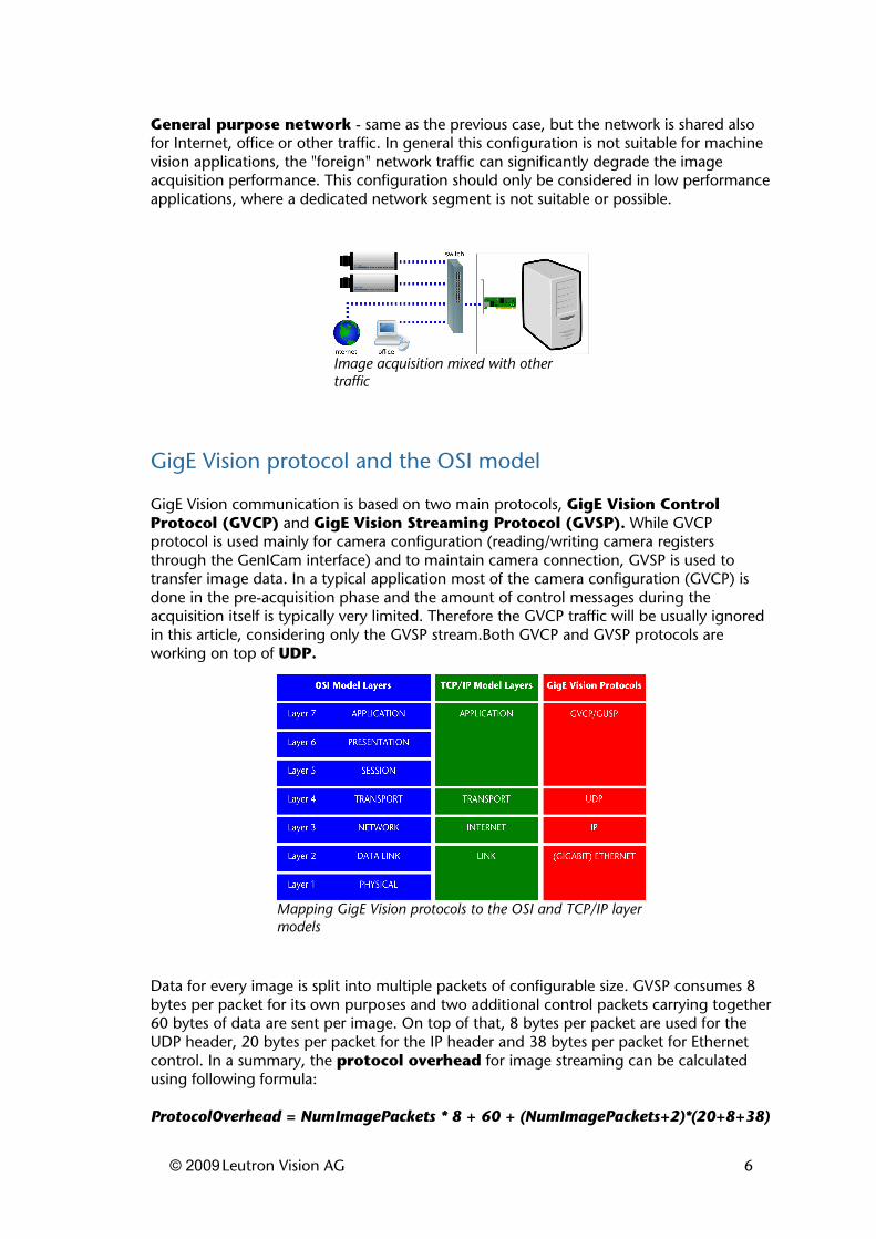
GigE Vision communication is based on two main protocols, GigE Vision Control Protocol (GVCP) and GigE Vision Streaming Protocol (GVSP). While GVCP protocol is used mainly for camera configuration (reading/writing camera registers through the GenICam interface) and to maintain camera connection, GVSP is used to transfer image data. In a typical application most of the camera configuration (GVCP) is done in the pre-acquisition phase and the amount of control messages during the acquisition itself is typically very limited. Therefore the GVCP traffic will be usually ignored in this article, considering only the GVSP stream.Both GVCP and GVSP protocols are working on top of UDP.
Data for every image is split into multiple packets of configurable size. GVSP consumes 8 bytes per packet for its own purposes and two additional control packets carrying together 60 bytes of data are sent per image. On top of that, 8 bytes per packet are used for the UDP header, 20 bytes per packet for the IP header and 38 bytes per packet for Ethernet control. In a summary, the protocol overhead for image streaming can be calculated using following formula:
ProtocolOverhead = NumImagePackets * 8 + 60 + (NumImagePackets+2)*(20+8+38)
© 2009Leutron Vision AG 6
Mapping GigE Vision protocols to the OSI and TCP/IP layer models
Image acquisition mixed with other traffic
Because the number of image packets is a function of packet size (the bigger the packet size, the less packets needed), also the overhead itself is a function of packet size. Leutron Vision provides a convenient calculator for the performance related quantities, allowing experimentation with the numbers corresponding with individual camera models and network configurations.The camera can be also configured to send additional data per image. This operation is known as "chunk mode" in GenICam terminology and allows transferring information such as timestamps, counters or other information with every image. This mode would of course slightly increase the amount of transferred data per image, however the amount of chunk data is very small compared to the image size (tens of bytes).Unless stated otherwise, the calculations in the following text will describe the case when the camera is streaming pure image without additional chunk data and without any packet resends.
Packet size, jumbo frames
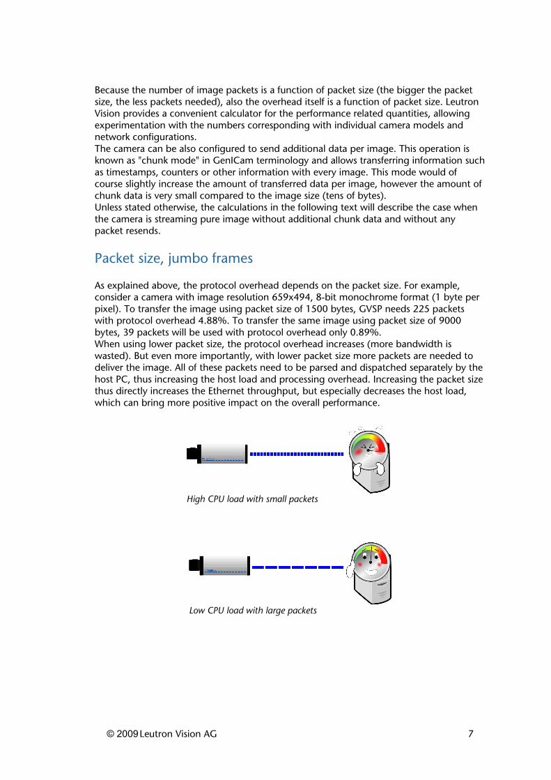
As explained above, the protocol overhead depends on the packet size. For example, consider a camera with image resolution 659x494, 8-bit monochrome format (1 byte per pixel). To transfer the image using packet size of 1500 bytes, GVSP needs 225 packets with protocol overhead 4.88%. To transfer the same image using packet size of 9000 bytes, 39 packets will be used with protocol overhead only 0.89%.When using lower packet size, the protocol overhead increases (more bandwidth is wasted). But even more importantly, with lower packet size more packets are needed to deliver the image. All of these packets need to be parsed and dispatched separately by the host PC, thus increasing the host load and processing overhead. Increasing the packet size thus directly increases the Ethernet throughput, but especially decreases the host load, which can bring more positive impact on the overall performance.
© 2009Leutron Vision AG 7
High CPU load with small packets
Low CPU load with large packets
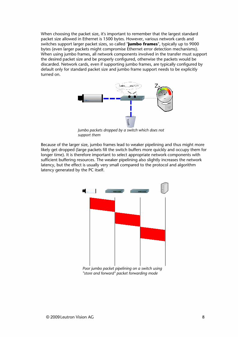
When choosing the packet size, it's important to remember that the largest standard packet size allowed in Ethernet is 1500 bytes. However, various network cards and switches support larger packet sizes, so called "jumbo frames", typically up to 9000 bytes (even larger packets might compromise Ethernet error detection mechanisms). When using jumbo frames, all network components involved in the transfer must support the desired packet size and be properly configured, otherwise the packets would be discarded. Network cards, even if supporting jumbo frames, are typically configured by default only for standard packet size and jumbo frame support needs to be explicitly turned on.
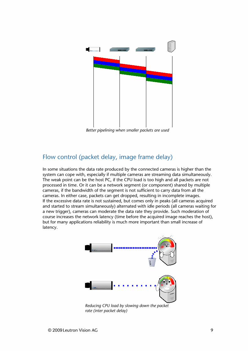
Because of the larger size, jumbo frames lead to weaker pipelining and thus might more likely get dropped (large packets fill the switch buffers more quickly and occupy them for longer time). It is therefore important to select appropriate network components with sufficient buffering resources. The weaker pipelining also slightly increases the network latency, but the effect is usually very small compared to the protocol and algorithm latency generated by the PC itself.
© 2009Leutron Vision AG 8
Poor jumbo packet pipelining on a switch using "store and forward" packet forwarding mode
Jumbo packets dropped by a switch which does not support them
Flow control (packet delay, image frame delay)
In some situations the data rate produced by the connected cameras is higher than the system can cope with, especially if multiple cameras are streaming data simultaneously. The weak point can be the host PC, if the CPU load is too high and all packets are not processed in time. Or it can be a network segment (or component) shared by multiple cameras, if the bandwidth of the segment is not sufficient to carry data from all the cameras. In either case, packets can get dropped, resulting in incomplete images.If the excessive data rate is not sustained, but comes only in peaks (all cameras acquired and started to stream simultaneously) alternated with idle periods (all cameras waiting for a new trigger), cameras can moderate the data rate they provide. Such moderation of course increases the network latency (time before the acquired image reaches the host), but for many applications reliability is much more important than small increase of latency.
© 2009Leutron Vision AG 9
Better pipelining when smaller packets are used
Reducing CPU load by slowing down the packet rate (inter packet delay)
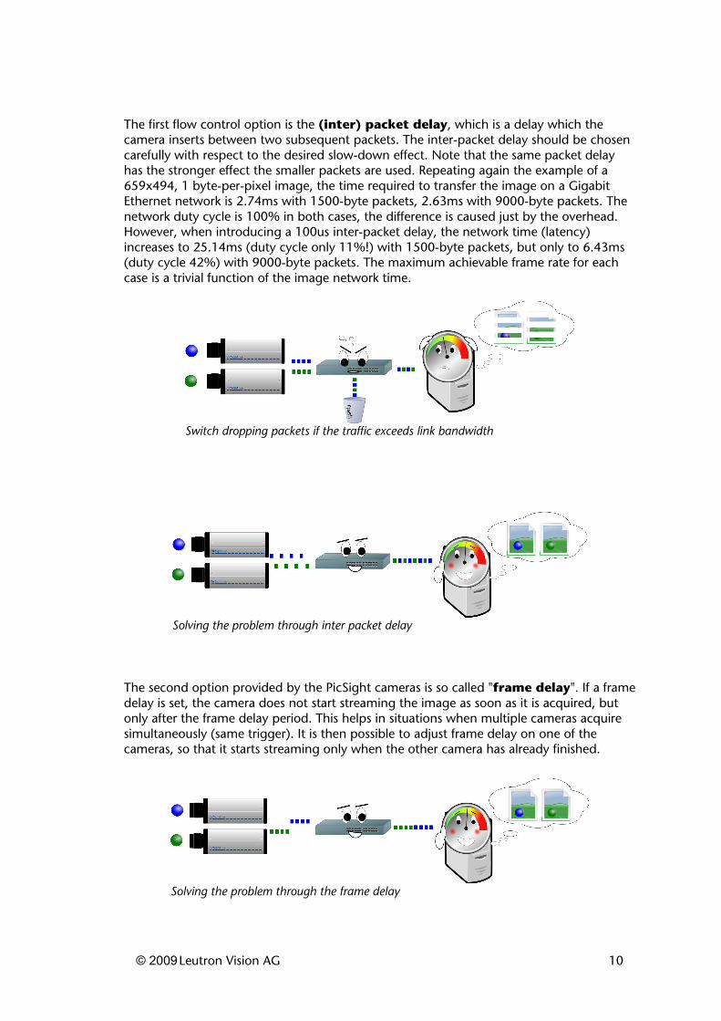
The first flow control option is the (inter) packet delay, which is a delay which the camera inserts between two subsequent packets. The inter-packet delay should be chosen carefully with respect to the desired slow-down effect. Note that the same packet delay has the stronger effect the smaller packets are used. Repeating again the example of a 659x494, 1 byte-per-pixel image, the time required to transfer the image on a Gigabit Ethernet network is 2.74ms with 1500-byte packets, 2.63ms with 9000-byte packets. The network duty cycle is 100% in both cases, the difference is caused just by the overhead. However, when introducing a 100us inter-packet delay, the network time (latency) increases to 25.14ms (duty cycle only 11%!) with 1500-byte packets, but only to 6.43ms (duty cycle 42%) with 9000-byte packets. The maximum achievable frame rate for each case is a trivial function of the image network time.
The second option provided by the PicSight cameras is so called "frame delay". If a frame delay is set, the camera does not start streaming the image as soon as it is acquired, but only after the frame delay period. This helps in situations when multiple cameras acquire simultaneously (same trigger). It is then possible to adjust frame delay on one of the cameras, so that it starts streaming only when the other camera has already finished.
© 2009Leutron Vision AG 10
Switch dropping packets if the traffic exceeds link bandwidth
Solving the problem through inter packet delay
Solving the problem through the frame delay
Host PC resources
The host PC, its resources, configuration and loading (both sustained and peak) are of the most important factors when considering the network performance.The host resources - particularly the processor time, but also the memory or PCI bus - need to be shared between image acquisition (packet processing), image processing (the application's main task) and possibly other actions performed by the computer.When the incoming data packets are processed by standard operating systems network stack, just the acquisition itself might consume a lot of precious processor time which is then not available for the application itself. The processing overhead is high and algorithm latency escalates. On the other hand, with overloaded processor, the image acquisition might not be fast enough to cope with the incoming data. Both sides would negatively influence each other. The problem can fortunately be solved by using a filter driver to dissect the GigE Vision packets - the driver dramatically decreases the CPU load required to process the packets and thus leaves the processor time for the application itself.A further portion of the CPU load may be saved by using a PicSight camera model capable of data preprocessing (such as Bayer decoding, color transformations, LUT's and the like).The slot connecting the network card might also play significant role. Note that the old-fashioned 32-bit/33MHz PCI bus hardly matches the Gigabit Ethernet bandwidth, moreover the conventional PCI bus is shared among all connected devices. Thus if the processed data are, for example, stored to the disk, the data are actually moved multiple times across the bus. PCI Express (PCIe) architecture allows higher bandwidth and also point-to-point connections allowing multiple simultaneous transfers. The PCI Express is thus much more suitable for high throughput applications.With high data rates, the network traffic can generate lots of interrupts causing frequent processor context switching and incurs excessive processing overhead (when using standard frame size the full speed Gigabit Ethernet traffic could generate over 80000 interrupts per second). The interrupt rate can be moderated by using larger packets (jumbo frames) for image streaming and configuring network card's driver options for interrupt throttling. The problem can get emphasized when another device generating a high number of interrupts is connected to the system, or even sharing the interrupt line with the network card.Another important consideration concerns the priority adjustments. If some application threads or processes are set to higher priority than the image acquisition threads (in particular when no filter driver is used and the acquisition threads need to perform the GigE Vision data dissection), then the image acquisition might be blocked by these high priority threads and again packets might get dropped. If adjusting the thread priorities is necessary, it should be understood that if a top-priority thread claims the processor for too long time, the image acquisition might fail.
© 2009Leutron Vision AG 11

Network card selection and configuration
To achieve good performance we recommend to use a network card based on the Intel PRO/1000 chipset. These adapters provide superior performance and various performance tuning options. We recommend the use of up-to-date device drivers (they exist for all versions of Windows and Linux operating systems).The network card performance can be configured through various device driver parameters. We'll discuss those most related to the network performance. Note that in Windows the parameters are configured through the driver properties dialog in the Device Manager. In Linux they can be configured (also depending on the driver version) either through module startup options (modprobe) and/or through standard network configuration tools (ifconfig, ethtool) and corresponding configuration files. We recommend studying the documentation corresponding to the actual driver version to get up-to-date information. Names of the individual parameters might slightly differ across operating systems and driver versions:
• Speed and Duplex: use always "auto detect" option, unless there's a good reason to set the mode manually.
• Jumbo Frames: switch the jumbo frames on, preferably the 9kB option. Remember that to use jumbo frames, all devices on the data path (switches) must support them and be configured to recognize them. Note that some boards may support 16kB jumbo frames - however, this option does not bring too big improvement over the 9kB option any more, while compromising the Ethernet error detection mechanisms.
• TCP/IP Checksum Offloading - switch on, the packet checksum computation will be done by the board itself instead of by the host processor, thus improving speed and saving CPU load.
• Receive/Transmit (Rx/Tx) Descriptors - these options configure the number of ring buffers used to store incoming packet data before processing (size of a single descriptor is usually 2kB). If the host CPU load gets too high and the packets are temporarily processed slower than they arrive, the ring buffer might overflow and then further packets get dropped. Increasing the number of ring buffer entries will help to survive such peaks. Because the amount of incoming data (images) will be much higher than the amount of outgoing data (camera control), you will usually need to touch only the Rx Descriptors option. If the system memory is not an issue, it might be good idea to always set the Rx Descriptor count to the maximum.
• Interrupt Moderation (Throttle) Rate (ITR) - as packets are arriving, the network card generates interrupts to inform the driver about data ready for processing. With high data rates, it might be desirable to reduce number of these interrupts and let the board deliver multiple packets per interrupt. This option allows to optimize packet processing and decrease CPU load, thus improving the system throughput. Because the small incurred increase of packet delivery latency is rarely an issue, we recommend switching the interrupt moderation rate to maximum. Only if minimizing the latency of small packets (used for camera control including e.g. the software triggering or for camera messages) is more important than the CPU load, then the ITR should be reduced or switched to the "adaptive" mode.
• Adaptive Inter-Frame Spacing - to be switched off. This option is irrelevant for full-duplex collision free Ethernet.
• Flow Control - to be switched off. Explicit flow control can be achieved through the packet delay settings.
© 2009Leutron Vision AG 12

When the expected data rate from the connected cameras exceeds the Gigabit Ethernet bandwidth and flow control techniques (such as inter-packet delay) are not an option, multiple network cards (or a multi-port card) can be used to scale the available bandwidth.
Switch selection and configuration
If the network configuration involves use of switches, these should be carefully selected according to the application performance requirements.First of all, obsolete components, such as network hubs should be avoided. Hubs and similar devices operating at the physical layer (OSI Layer 1) work as a dummy repeaters. All connected devices thus share the same collision domain and can work only in half-duplex mode (just one side relaying at a time).An Ethernet switch operates at least at the data link layer (OSI Layer 2) or at higher layers (for multicasting configurations a Layer 3 switch with multicasting support will be needed). It examines each packet and instead of repeating it on each port, it forwards it only to the correct destination, thus splitting the network to separate collision domains per segment. Every network segment (cable) is thus separated from the others and Ethernet collisions are fully eliminated. When both ends are capable and working in full-duplex mode, the full Gigabit Ethernet bandwidth is available in both directions.
Most important switch parameters to observe:
• The switch should be properly configured for proper link speed (1Gbps) and full-duplex operation. The switch is usually by default configured to auto negotiate these parameters, which is also the recommended option.
• The switch should support and be configured for jumbo frames. It is important that all devices on the path support the packet size used by the camera(s) for image streaming.
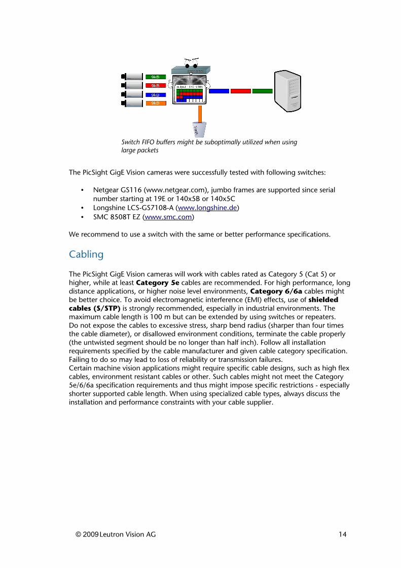
• Depending on the network configuration, number of used cameras and expected peak data rate, the switch should have sufficient packet forwarding capability (non-blocking operation) and packet queue buffer memory. This becomes particularly important when multiple cameras are connected to the switch and possibly sharing a common uplink to the host PC. Many modern switches can forward packets with full speed of all the switch ports. However, if the destination link is occupied by traffic from other ports, the switch has to queue and delay the packet. If such excessive data rate is not sustained, but comes in peaks, sufficient queue memory size on the switch can solve the problem. Finally note that if the switch offers low queue memory size per port, it's more likely to overflow when higher packet sizes are used. For example when the switch features 32kB buffer per port and using 9kB jumbo frames, just three packets (27kB) fit in the buffer (fourth incoming buffer would be dropped) and the remaining 5kB are permanently unused.
• Power over Ethernet (PoE) support if required by the application.• Other specific switch parameters and configuration options should be studied
carefully. If the switch for example uses a spanning tree protocol, significant delay (30-60 seconds) might occur before the connection is established with a newly connected device. Because for a typical machine vision configuration spanning tree protocol brings no advantage, we recommend switching it off.
• Latency sensitive applications could need to observe the packet forwarding latency.
© 2009Leutron Vision AG 13
The PicSight GigE Vision cameras were successfully tested with following switches:
• Netgear GS116 (www.netgear.com), jumbo frames are supported since serial number starting at 19E or 140x5B or 140x5C
• Longshine LCS-GS7108-A (www.longshine.de)• SMC 8508T EZ (www.smc.com)
We recommend to use a switch with the same or better performance specifications.
Cabling
The PicSight GigE Vision cameras will work with cables rated as Category 5 (Cat 5) or higher, while at least Category 5e cables are recommended. For high performance, long distance applications, or higher noise level environments, Category 6/6a cables might be better choice. To avoid electromagnetic interference (EMI) effects, use of shielded cables (S/STP) is strongly recommended, especially in industrial environments. The maximum cable length is 100 m but can be extended by using switches or repeaters. Do not expose the cables to excessive stress, sharp bend radius (sharper than four times the cable diameter), or disallowed environment conditions, terminate the cable properly (the untwisted segment should be no longer than half inch). Follow all installation requirements specified by the cable manufacturer and given cable category specification. Failing to do so may lead to loss of reliability or transmission failures.Certain machine vision applications might require specific cable designs, such as high flex cables, environment resistant cables or other. Such cables might not meet the Category 5e/6/6a specification requirements and thus might impose specific restrictions - especially shorter supported cable length. When using specialized cable types, always discuss the installation and performance constraints with your cable supplier.
© 2009Leutron Vision AG 14
Switch FIFO buffers might be suboptimally utilized when using large packets
Filter drivers
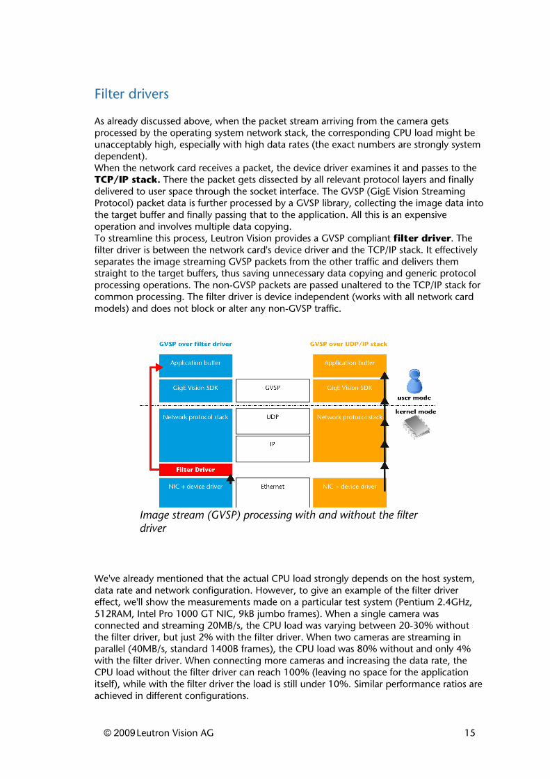
As already discussed above, when the packet stream arriving from the camera gets processed by the operating system network stack, the corresponding CPU load might be unacceptably high, especially with high data rates (the exact numbers are strongly system dependent).When the network card receives a packet, the device driver examines it and passes to the TCP/IP stack. There the packet gets dissected by all relevant protocol layers and finally delivered to user space through the socket interface. The GVSP (GigE Vision Streaming Protocol) packet data is further processed by a GVSP library, collecting the image data into the target buffer and finally passing that to the application. All this is an expensive operation and involves multiple data copying.To streamline this process, Leutron Vision provides a GVSP compliant filter driver. The filter driver is between the network card's device driver and the TCP/IP stack. It effectively separates the image streaming GVSP packets from the other traffic and delivers them straight to the target buffers, thus saving unnecessary data copying and generic protocol processing operations. The non-GVSP packets are passed unaltered to the TCP/IP stack for common processing. The filter driver is device independent (works with all network card models) and does not block or alter any non-GVSP traffic.
We've already mentioned that the actual CPU load strongly depends on the host system, data rate and network configuration. However, to give an example of the filter driver effect, we'll show the measurements made on a particular test system (Pentium 2.4GHz, 512RAM, Intel Pro 1000 GT NIC, 9kB jumbo frames). When a single camera was connected and streaming 20MB/s, the CPU load was varying between 20-30% without the filter driver, but just 2% with the filter driver. When two cameras are streaming in parallel (40MB/s, standard 1400B frames), the CPU load was 80% without and only 4% with the filter driver. When connecting more cameras and increasing the data rate, the CPU load without the filter driver can reach 100% (leaving no space for the application itself), while with the filter driver the load is still under 10%. Similar performance ratios are achieved in different configurations.
© 2009Leutron Vision AG 15
Image stream (GVSP) processing with and without the filter driver
Note that also the foreign (non GigE Vision) network traffic needs to pass the filter driver as well, being just forwarded to the standard network stack. Thus the effect on the foreign traffic is negative, however quite small (within 10%). The amount of foreign traffic during image acquisition should be very limited, if not zero.Because PicSight-GigE cameras are fully compatible with GigE Vision and GenICam (including GenICam Transport Layer a.k.a. GenTL) standards, they can be freely used with other GigE Vision/GenICam compliant software packages. Some of these packages also provide filter drivers, which should always be considered to reduce the protocol related CPU load.Some software packages provide different types of drivers called "high performance" or similar. Such drivers fully replaces the original network card's driver, turning the network card into a dedicated image acquisition device. Such a device then recognizes only the camera related packets, other network traffic is ignored. While providing only marginal performance advantage over a filter driver, these dedicated drivers disable any non GigE Vision communication over the port, thus prohibiting use of any other Ethernet based industrial devices in the system. The dedicated driver will also work only with the single network chipset it was designed for, thus limiting the network card choice. For these reasons, the filter driver is a preferred option.
© 2009Leutron Vision AG 16
Input/output interface
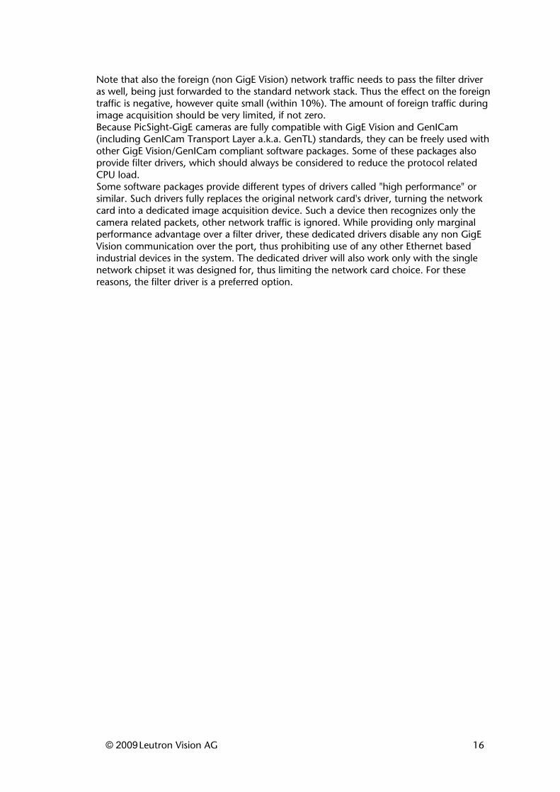
When using Gigabit Ethernet cameras, it's important to understand the slight difference between hardware and software triggering. A hardware trigger (physical pulse issued to one of the camera's general purpose inputs) provides very predictable and fast response - several tens of microseconds from the trigger to actual start of the exposure (the number is model specific and depends on the sensor used) and practically no jitter. It's useful to know that the TTL input is faster than the optocoupler input and that the optocoupler input has asymmetric timing characteristics (rising edge is faster than the falling edge).On the other hand, when using the software trigger, the trigger command has to be sent to the camera via the network and is thus exposed to all corresponding effects such as passing the TCP/IP stack on the host, the full network path or even possible packet corruption or loss and need for resend. While the added latency is not too high, when compared to the complete system latency per image, the real-time sensitive applications might worry about the jitter. The time from issuing the software command to the start of exposure depends not only on the camera sensor, but especially on the host PC and network configuration. To give an example, values measured on a given testing system varied between 310 to 570 microseconds - however these particular numbers cannot be taken too seriously, because they are strongly system dependent.
Similar latency and jitter as described for the software trigger has to be considered for the software access to the camera's general purpose I/O interface (TTL or optocoupler outputs). If the processing results need to be signaled to the external devices through the camera GPIO, the command adjusting the outputs has to be sent over the Ethernet. Similarly as with the trigger itself, the added delay is very small compared to the complete latency (including the image transfer and processing).GigE Vision based frame grabbers exist to solve the host load and I/O access limitations, however they bring an additional cost unjustifiable for vast majority of applications. The use of filter driver and possibly on-camera preprocessing (RTF and Smart PicSight models) provides in most cases the desired effect.
© 2009Leutron Vision AG 17
Sample measurements of trigger latency (model P52B)
PicSight RTF and Smart models
The PicSight family of GigE Vision cameras is versatile and offers various models which can help to reduce the host CPU and network load.The PicSight "RTF" (Real Time Function) models support various image preprocessing operations which would otherwise be performed by the host itself. Examples are Bayer pattern decoding, color transformations or LUT's.The PicSight-Smart family goes even further providing a fully programmable on-camera environment. The smart cameras feature a RISC processor, real-time operating system and C/C++ based SDK supporting image acquisition and processing, camera configuration, I/O access, streaming and network access and other functions. The application running on the smart camera can co-operate with the host side, performing part of the job and offloading the host and/or network. Or the camera can even run in standalone mode, when the host is not needed.
Using 100Mb/s Ethernet
The PicSight-GigE cameras can be used in the 100Mb/s (Fast Ethernet) environments. However, the network performance would not be sufficient for most applications and the network wouldn't even be able to deliver the image data at full frame rate.The 100Mb/s Ethernet equipment might also not support jumbo frames and other performance options discussed before.A specific problem can also occur in a mixed environment. If the camera is connected to a switch over a 1Gb/s link, but another 100Mb/s link occurs within the path to the host, the camera will not know about that bottleneck and will stream the image data in full 1Gb/s speed. The slow link will not be able to cope with those data and packets will get dropped. The problem can be compensated by configuring proper packet delay on the camera.
Summary
The Gigabit Ethernet based machine vision systems offer throughput over 100MB/s, moreover well scalable using multiple network cards. The CPU load bound to the image acquisition is within acceptable limits, especially when using the filter drivers. The latency related to the image transfer depends on the network configuration, number of connected cameras and flow control settings (such as inter-packet delay), but is well predictable. The I/O related jitter (if it is an issue) can be eliminated by using hardware instead of software triggering. In conclusion, the GigE Vision systems provide excellent performance and together with other aspects such as cost effectiveness, availability, flexibility or long distance operation, they beat the competing technologies in most areas.
© 2009Leutron Vision AG 18