Getting Started With - Vectric · PDF fileGetting Started With Tutorial 1 Bulls Head Sign....
20
G G e e t t t t i i n n g g S S t t a a r r t t e e d d W W i i t t h h Tutorial 1 Bulls Head Sign
Transcript of Getting Started With - Vectric · PDF fileGetting Started With Tutorial 1 Bulls Head Sign....

GGeettttiinngg SSttaarrtteedd WWiitthh
Tutorial 1 Bulls Head Sign

VCarve Pro
Disclaimer
All CNC machines (routing, engraving, and milling) are potentially dangerous and because Vectric Ltd has no control over how the software described in this manual might be used. Vectric Ltd or any associated Resellers cannot accept responsibility for any loss or damage to the work piece, machine or any individual, howsoever caused by misusing the software. Extreme care should always be taken and the output from the software thoroughly checked before sending it to a CNC machine.
The information in this manual may be subject to change without any prior notice. The software described in this manual is supplied under the terms and conditions of the software license agreement and may only be used in accordance with the terms of this agreement.
© Vectric Ltd
26 Peterbrook Close Redditch B98 7YF
UK
www.vectric.com
E-mail [email protected] Phone +44 (0) 1527 460 459
Fax +44 (0) 1527 460 459

Table of Contents What is V-Carving?........................................................................................... 2 What the software allows you to do .................................................................. 3 What file formats can be used? ........................................................................ 3 Getting Help...................................................................................................... 3 Watch the supporting tutorial videos................................................................. 3 Overview of the interface .................................................................................. 4
The VCarve Pro Logic....................................................................... .........................5 Managing windows - Auto Show / Hide............................................. .........................6
View Controls.................................................................................................... 7
2D Design Window ........................................................................... .........................7 3D Window ....................................................................................... .........................7
Vectors.............................................................................................................. 8
Vector selection methods.................................................................. .........................8 Vector deselect ................................................................................. .........................8 Vector editing .................................................................................... .........................9 Drawing shapes ................................................................................ .........................9
Tutorial 1 3D V-Cared Pub Sign............................................................ 10 Introduction ..................................................................................................... 10 1. Opening the Design............................................................................... 11 2. Select the Vectors to V-Carve ............................................................... 12 3. Calculate the V-Carve Toolpath ............................................................ 13 4. Preview the finished job......................................................................... 16 5. Estimating the Machining Times............................................................ 17 6. Editing and Saving the 3D V-Carved Toolpath...................................... 17

2
Introduction Many businesses use their CNC machine for simply cutting out flat letters and shapes from plastic sheet, or engraving standard badges and nameplates, which are all based on simple 2D machining strategies. VCarve Pro can handle all these day to day tasks, however this tutorial will show you how to use your CNC machine to route and engrave jobs that include decorative 3D designs that will be more interesting and hopefully more profitable if you run a business.
The manual takes you step-by-step through an illustrated tutorials that shows and explains exactly how to use the VCarve Pro Software. Tips and tricks have also been included that will help you get the most from your CNC machine.
We hope you enjoy using the software.
What is V-Carving? V-Carving produces a constantly varying and flowing 3D carved effect on the job, which is similar to how a craftsman would carve by hand. Imagine a ‘hand-carver’ cutting letters into a piece of wood or stone, starting at a sharp corner, pushing the chisel deeper where the font stroke gets wider and pulling the tool out to form precise, sharp corners. V-Carving, also known as 3D Engrave or Intaglio engraving allows a V shaped or engraving tool to cut at varying Z depths that are directly linked to the width of the geometry in which the cutter is moving.
This is effect is difficult to describe in words, but imagine using a flat-bottom end mill to cut 3mm (1/8th) deep inside the text shown below. The tool, being round will always leave a fillet radius in the corners and will not actually cut the complete letter where the diameter of the tool is too big to pass through the small gaps.
Sign including V-Carved Text
3
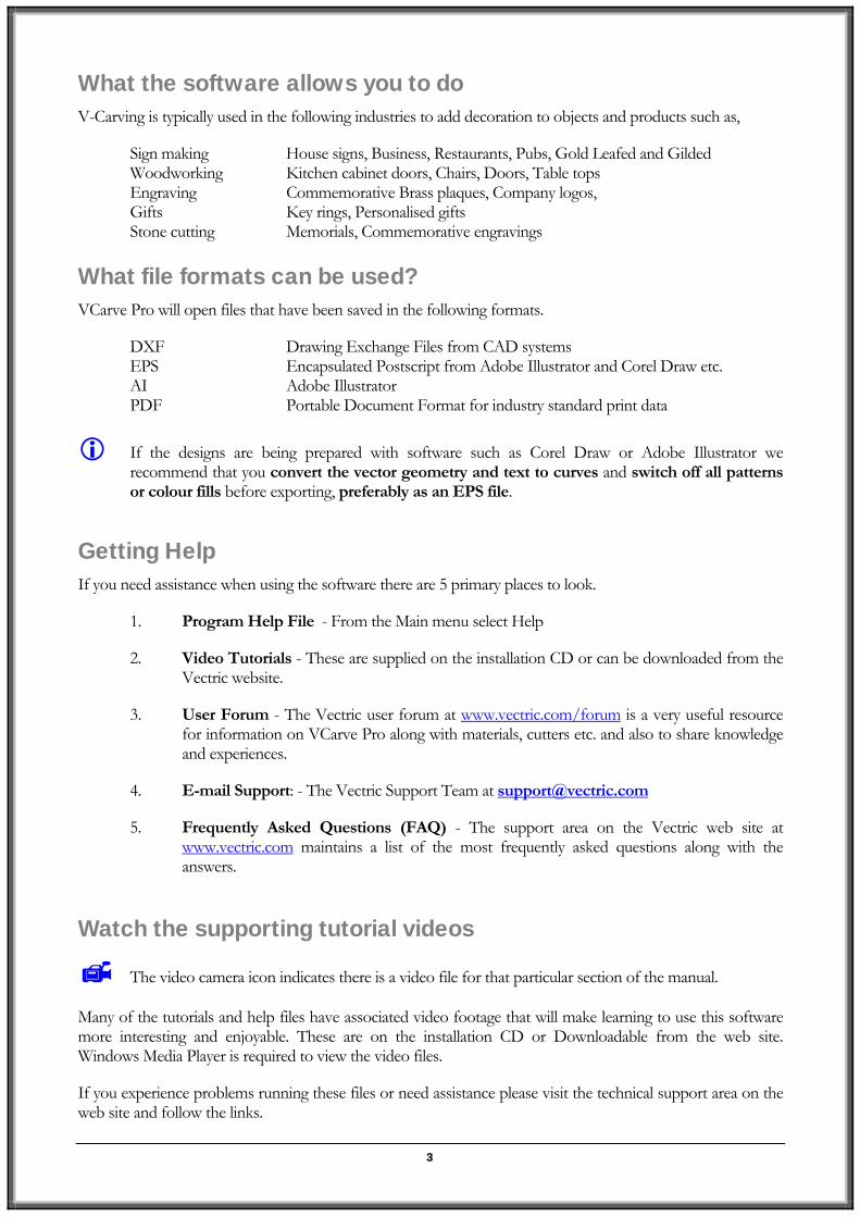
What the software allows you to do V-Carving is typically used in the following industries to add decoration to objects and products such as,
Sign making House signs, Business, Restaurants, Pubs, Gold Leafed and Gilded Woodworking Kitchen cabinet doors, Chairs, Doors, Table tops Engraving Commemorative Brass plaques, Company logos, Gifts Key rings, Personalised gifts Stone cutting Memorials, Commemorative engravings
What file formats can be used? VCarve Pro will open files that have been saved in the following formats.
DXF Drawing Exchange Files from CAD systems EPS Encapsulated Postscript from Adobe Illustrator and Corel Draw etc. AI Adobe Illustrator PDF Portable Document Format for industry standard print data
If the designs are being prepared with software such as Corel Draw or Adobe Illustrator we
recommend that you convert the vector geometry and text to curves and switch off all patterns or colour fills before exporting, preferably as an EPS file.
Getting Help If you need assistance when using the software there are 5 primary places to look.
1. Program Help File - From the Main menu select Help
2. Video Tutorials - These are supplied on the installation CD or can be downloaded from the Vectric website.
3. User Forum - The Vectric user forum at www.vectric.com/forum is a very useful resource for information on VCarve Pro along with materials, cutters etc. and also to share knowledge and experiences.
4. E-mail Support: - The Vectric Support Team at [email protected]
5. Frequently Asked Questions (FAQ) - The support area on the Vectric web site at www.vectric.com maintains a list of the most frequently asked questions along with the answers.
Watch the supporting tutorial videos
The video camera icon indicates there is a video file for that particular section of the manual.
Many of the tutorials and help files have associated video footage that will make learning to use this software more interesting and enjoyable. These are on the installation CD or Downloadable from the web site. Windows Media Player is required to view the video files.
If you experience problems running these files or need assistance please visit the technical support area on the web site and follow the links.

4
Overview of the interface The screen area is split into 6 main regions.
1. The Main Menu bar along the top of the screen provides access to additional, less commonly used commands available in the software. Simply click and each option will show a drop-down list of the functions.
2. The Drawing Tab on the left side of the screen provides general drawing tools for design modification, sizing, alignment etc. prior to machining.
3. The Toolpath Tab on the right side of the screen is where toolpaths are defined, calculated, edited and deleted. The Material set-up and Job Preview tools are also in this area.
4. The Command forms automatically appear in the Drawing window and the Toolpath tabs when tools are selected that require details to be entered such as dimensions for sizing or positioning etc.
5. The 2D Design window is where the design is drawn, edited and selected ready for machining. Designs can be imported or created directly in VCarve Pro. This occupies the same area as the 3D Preview window and the display can be toggled between the two using F2 and F3 or the tabs at the top of the window.
6. The 3D Preview window shows the calculated toolpaths and colour shaded carved job are displayed.
The User Interface
6
4
3
4
2
1 5

5
The VCarve Pro Logic
VCarve Pro has been developed specifically to open decorative designs and calculate perfect 3D V-Carve / 3D Engrave toolpaths as quickly and easily as possible. The general work flow logic to apply to most jobs is explained in the diagram below.
Although VCarve Pro’s key strength is the toolpath engine it also includes drawing and editing tools that allow design modifications such as positioning, alignment changes and node editing to be made. Multiple design elements can also be imported, scaled, positioned and interactively edited to make a new design. Text can also be created using any TrueType font installed on your computer.
1 Open or Import the
vector design
2 Select the regions to V-Carve or machine
3 Specify the tool
details and calculate toolpaths
4 Preview the job in
any material
5 Save the CNC code

6
Managing windows - Auto Show / Hide
The two primary Drawing and Toolpath Tabs have Auto Hide / Show behaviour which allows them to automatically close when not being used, maximizing the working screen area. They can be opened and closed at any time by clicking the left mouse over the Drawing and Toolpaths tabs in the top left and top right corners of the interface.
Click on the Drawing Tab to open the Drawing Window
Click on the Toolpaths Tab to open the Toolpaths Window
Clicking on the Drawing or Toolpath tab will also close an open window.
Both windows have Auto Hide / Show behavior and can be locked open by clicking on the Push-Pin button in the top right corner of the window region as shown below.
Auto Hide / Show windows
Lock Open Auto hide

7
View Controls The View Control options available when working in the 2D Design and 3D Preview windows are,
2D Design Window
Zoom Interactive Mouse with Middle Wheel – Push / Pull
Zoom Box Click top left corner Click bottom right corner
Pan Click and hold the Left mouse button – Esc to cancel Shortcut: Click and drag the Middle mouse button
Zoom Extents Zooms to show material limits in the 2D window
Zoom Selected
Click to select an object or objects Zooms to the bounding box of the selections
Mouse with Middle Wheel can be used to interactively zoom in / out.
3D Window
3D Twiddle Click and drag Left mouse button in the 3D window
Zoom Right mouse button – Push / Pull Mouse with Middle Wheel – Push / Pull
Pan Click and drag Right mouse button + Ctrl
Click and drag Right and Left mouse button
Plan View
Looks directly down the Z axis onto the design in 3D window
Isometric View
Shows the model in a 3D isometric view in the 3D window
Pressing F2 & F3 will toggle between displaying the 2D & 3D windows

8
Vectors Decorative vector designs and shapes will often be imported from another drawing package such as Corel
in VCarve Pro. The imported vector shape(s) can be modified, moved, scaled, rotated, mirrored or deleted.
Vector selection methods
Multiple
3. Moving the cursor from ght to Left selects all o the selection rectangle and also
rner of the objects and and then with the mouse button held down, drag the mouse to the corresponding Bottom or Top Left corner and release the mouse button. This selects all objects inside the selection rectangle + any that the selection touches.
4. Pressing the keyboard keys Ctrl + A will select all vector objects in the design
s dotted purple lines.
Vec
Selections can be cancelled by simply,
1. Left clicking on an area outside the selection
2. Pressing the Right mouse button and selecting Unselect All (top option) from the list. You must click on the white drawing background to get this option in the menu.
Draw, AutoCAD etc. rather than being completely drawn
vectors can be selected in the following 4 ways.
1. Manual multiple selection
Hold down the Shift key while clicking the Left mouse button on each vector required.
Objects can be deselected simply clicking on the object again with the Shift key pressed.
2. Moving the cursor from Left to Right selects only FULLY enclosed objects.
Click the left mouse button to the Top Left or Bottom Left of the objects and then with the mouse button held down, drag the mouse to the corresponding opposite Bottom Right or Top Right corner and release the mouse button. This selects all objects fully inside the rectangle.
Ri bjects INSIDEany objects that the selection rectangle TOUCHES.
Click the left mouse button Top or Bottom Right co
Selected vectors are displayed a
tor deselect

9
Vector editing
A design is created from vector lines, arcs and bezier spans, which all have different properties that can be selected, modified and moved at any time.
Vector Selection Tool Selected from the Drawing tab on the left
Selected vectors are shown as dotted purple lines. Vectors need to be selected before any of the editing tools such as scaling and moving etc. can be used.
Node Editing Tool Selected from the Drawing tab on the left
Vectors selected Bezier node editing
When the Node Editing tool is active the cursor changes to a Black Arrow indicating that individual points (nodes) can be edited. Nodes can be interactively moved by clicking the left mouse button over a node and dragging to move the node to a new position.
The shape of lines, arcs and bezier spans can be edited by clicking on the nodes or control points then dragging to where the point is to move to.
If you right click on nodes or spans a context sensitive popup menu will be displayed which allows you to insert or delete points and nodes, cut the vector, move the start point etc.
Drawing shapes Simple shapes and designs can be drawn using the Circle, Oval, Rectangle and Polyline options. These shapes are commonly used to create new borders for signs or as a reference plate for a kitchen cabinet door etc. Shapes can be created by either entering exact dimensions in the Command Window or simply clicking the left mouse button in the 2D window to specify the parameters and coordinates interactively.
Drawing shapes is covered in more detail during the tutorials in this manual.

10
Tutorial 1 3D V-Cared Pub Sign
We recommend that you watch the 5 minute Video for this Tutorial before proceeding. The video can be found on the installation CD or downloaded from the web site at www.vectric.com
Introduction This tutorial will show you how to 3D V-Carve the Pub Sign shown below in Figure 1, which is approximately 12” (300mm) wide by 4.5” (115mm) high. The artwork for this sign has been drawn using Corel Draw and saved as a DXF file.
We estimate that this tutorial should take you approximately 15 minutes to complete.
Figure 1. The finished Pub Sign
There are 6 key stages in opening and preparing toolpaths for this sign.
1. Open / Import the design
2. Select the vectors to V-Carve
3. Calculate the 3D V-Carved toolpath
4. Preview the completed job
5. Estimate the machining time
6. Save the Toolpaths
The file required for this tutorial are installed on your PC in the folder,
C:\ Program Files\VCarve Pro 3.0\Sample Files\Bulls_Head.dxf
NOTE: If you are using the Trial version of VCarve Pro, you will need to load the file Bulls_Head.crv if you want to be able to save and cut the toolpaths.

11
1. Opening the Design
1. From the Startup Tasks tab toolbar click on the Open an existing file icon.
2. Navigate to the folder - C:\ Program Files\VCarve Pro 3.0\Sample Files
3. Select the file named – Bulls_Head.dxf and click the Open button
The design shown below in Figure 2 will now be displayed in the 2D window and the Material Setup form is opened.
Figure 2 Original vector design
Note: The horizontal and vertical dotted pale grey lines represent the X0 and Y0 axes.
12
4. Complete this form as shown above
Width (X)= 12” Height (Y) = 4.5”
Material Thickness = 0.5”
Z Zero on the Material Surface
Click X0, Y0 Origin to be bottom Left corner
Check the option – Center vectors in material
Select the Units = Inches
Click OK to set the material size and place the vector design in the middle
2. Select the Vectors to V-Carve
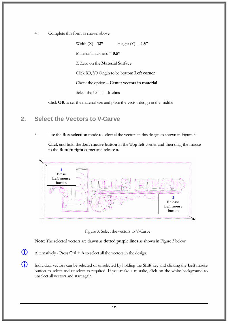
5. Use the Box selection mode to select al the vectors in this design as shown in Figure 3.
Click and hold the Left mouse button in the Top left corner and then drag the mouse to the Bottom right corner and release it.
Figure 3. Select the vectors to V-Carve
Note: The selected vectors are drawn as dotted purple lines as shown in Figure 3 below.
Alternatively - Press Ctrl + A to select all the vectors in the design.
Individual vectors can be selected or unselected by holding the Shift key and clicking the Left mouse button to select and unselect as required. If you make a mistake, click on the white background to unselect all vectors and start again.
1 Press
Left mouse button
2 Release
Left mouse button

13
3. Calculate the V-Carve Toolpath The design is now ready to calculate the v-carving toolpath.
6. From the View Control area select the Switch to Toolpaths tab .
This automatically closes the Drawing Tab and opens the Toolpath Tab on the Right side of the screen as shown below in Figure 4.
Figure 4. Toolpath Tab
To re-open the Drawing Tab simply click the cursor on the Drawing icon in the Top Left corner of the screen and the drawing tools will automatically appear.
The Drawing and Toolpath Tabs have an Auto Hide and Show behavior, which allows them to automatically close when not being used, maximizing the working screen area.
Click the Push-Pin to lock them in the Open position as shown below in Figure 5.
Figure 5. Auto Hide & Show windows
Toolpath Tab
Lock Open Auto hide

14
7. Select the Material Setup icon from the Toolpath Operations list on the Toolpaths tab and specify the Rapid Clearance Gap to be 0.2” and Home positions to be X0, Y0, Z2” as shown below in Figure 6.
Figure 6. Material Setup
Note that the Z Zero position is set to the top of the material.
8. Next, select the Create V-Carve Toolpath icon from the Toolpath Operations list and complete the form as shown below in Figure 7.
In this example we are cutting wood with a 0.5” (12mm) Diameter, 90 degree included angle V-Carving tool and the maximum cut depth per pass will be set to 0.20” (5mm), this can be greater if cutting soft materials.

15
Figure 7. V-Carve Toolpath parameters
Click on the Select button to open the Tool Database and select the tool shown below.
Important The Cutting Parameters should be set for the material you are cutting
Click the Edit button to modify the cutting parameters to match the tooling you are using and the material being machined
9. Click the Calculate button and the resulting toolpath will automatically be drawn in the 3D view and the Preview job form opened, as shown below in Figure 8.
Figure 8. 3D View showing Toolpath & Material
To rotate the model Click and hold the Left mouse button.
16
To zoom, use Middle Wheel on mouse or Push / Pull the Right mouse button
Pan using Ctrl + Right mouse button or the Left + Right mouse buttons together
For the standard views use the ISO and Plan view icons in the top right corner of the 3D view.
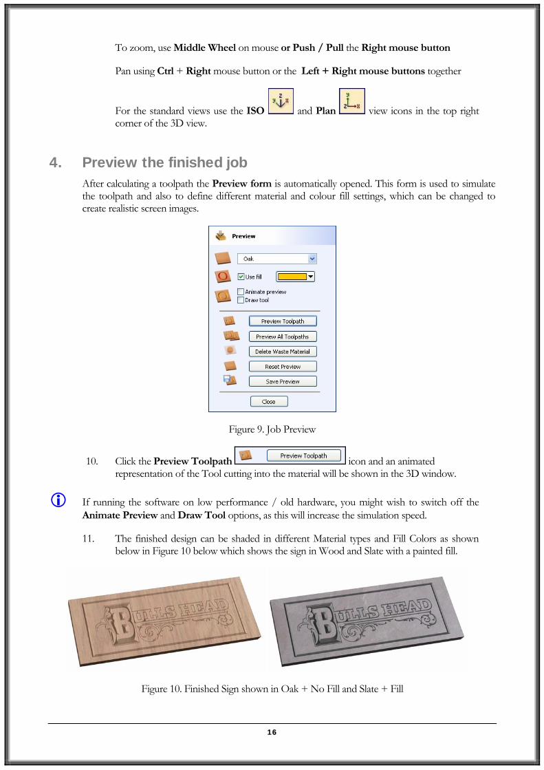
4. Preview the finished job After calculating a toolpath the Preview form is automatically opened. This form is used to simulate the toolpath and also to define different material and colour fill settings, which can be changed to create realistic screen images.
Figure 9. Job Preview
10. Click the Preview Toolpath icon and an animated representation of the Tool cutting into the material will be shown in the 3D window.
If running the software on low performance / old hardware, you might wish to switch off the Animate Preview and Draw Tool options, as this will increase the simulation speed.
11. The finished design can be shaded in different Material types and Fill Colors as shown below in Figure 10 below which shows the sign in Wood and Slate with a painted fill.
Figure 10. Finished Sign shown in Oak + No Fill and Slate + Fill

17
12. Click the Save Preview button to save the 3D window as an image file (bmp, jpg or gif) for use in customer quotations, marketing brochures or web site pictures etc.
5. Estimating the Machining Times
13. Selecting the Estimate Machining Times icon displays the estimated time required to machine the job in hours, minutes and seconds.
The Rapid Rate is the maximum feed rate at which the machine travels.
The Scaling Factor can be set to obtain more realistic estimates for jobs that include lots of complex 3D carved moves, where the machine may not run at the programmed feed rates due to the need to accelerate and decelerate when the tool changes direction.
6. Editing and Saving the 3D V-Carved Toolpath
Calculated toolpaths can be edited by either,
Clicking the Edit Toolpath icon . or Double clicking on the name of the Toolpath name in the Toolpath List.
14. Save the Toolpaths by clicking the Save Toolpath icon.

18
Figure 10. Save Toolpath
15. From the pull-down list of postprocessors, select the appropriate one for your CNC machine as shown above in Figure 10.
16. Click the Save button and enter a name to save the toolpath with.
Take extreme care to ensure the material and cutter are setup correctly before using the toolpath.
NOTE: If you are using the Trial version of VCarve Pro you must load the Bulls_Head.crv file to be able to save the toolpaths.