Getting Started With the CC13xx and CC26xx Sensor Controller · Getting Started With the CC13xx and...
23
1 SWRA578 – October 2017 Submit Documentation Feedback Copyright © 2017, Texas Instruments Incorporated Getting Started With the CC13xx and CC26xx Sensor Controller Application Report SWRA578 – October 2017 Getting Started With the CC13xx and CC26xx Sensor Controller Mandus Börjesson ABSTRACT This application note is intended to be an introduction to the low-power Sensor Controller Engine in CC13xx and CC26xx devices. It explains the benefits of using the Sensor Controller in various use cases. The application note also describes how to get started using the Sensor Controller and directs users to the required tools and collaterals. Contents 1 Introduction ................................................................................................................... 3 1.1 Background .......................................................................................................... 4 2 Device Overview ............................................................................................................. 5 2.1 Software.............................................................................................................. 5 2.2 Hardware............................................................................................................. 5 2.3 Recommended Reading ........................................................................................... 5 3 Device Description ........................................................................................................... 5 3.1 Getting Started With Sensor Controller Studio.................................................................. 5 4 Performance Comparison ................................................................................................. 13 4.1 Scenario Descriptions ............................................................................................ 13 5 Results ....................................................................................................................... 15 5.1 SPI – 18-Byte Transmission ..................................................................................... 15 5.2 ADC – Wake Up and Perform an ADC Read Operation ..................................................... 17 5.3 Comparator Reading.............................................................................................. 18 5.4 Waking Up and Returning to Sleep Immediately.............................................................. 19 5.5 Wake-Up and Shutdown ......................................................................................... 20 5.6 Pin Change Interrupt .............................................................................................. 21 6 Conclusion .................................................................................................................. 22 7 References .................................................................................................................. 22 List of Figures 1 Block Diagram Highlighting CC26xx Sensor Controller ................................................................ 3 2 Sensor Controller Studio Start Page ...................................................................................... 6 3 Project Window .............................................................................................................. 6 4 Task Window ................................................................................................................. 7 5 Sensor Controller Studio Editor Panel .................................................................................... 8 6 I/O Mapping Window ........................................................................................................ 8 7 Fill Out Fields for state.ledState Data Member .......................................................................... 9 8 Task Testing Window ...................................................................................................... 10 9 OBS_PWR_DWN (Top), Output Pin (Bottom) ......................................................................... 14 10 First Marker Before Application, Second Marker Before Next Application ......................................... 14 11 SPI Current Consumption ................................................................................................. 16 12 Current Traces for One Wake-Up of an SPI Application Running on Different Hardware........................ 16 13 ADC Current Consumption ............................................................................................... 17
Transcript of Getting Started With the CC13xx and CC26xx Sensor Controller · Getting Started With the CC13xx and...

1SWRA578–October 2017Submit Documentation Feedback
Copyright © 2017, Texas Instruments Incorporated
Getting Started With the CC13xx and CC26xx Sensor Controller
Application ReportSWRA578–October 2017
Getting Started With the CC13xx and CC26xx SensorController
MandusBörjesson
ABSTRACTThis application note is intended to be an introduction to the low-power Sensor Controller Engine inCC13xx and CC26xx devices. It explains the benefits of using the Sensor Controller in various use cases.The application note also describes how to get started using the Sensor Controller and directs users to therequired tools and collaterals.
Contents1 Introduction ................................................................................................................... 3
1.1 Background .......................................................................................................... 42 Device Overview ............................................................................................................. 5
2.1 Software.............................................................................................................. 52.2 Hardware............................................................................................................. 52.3 Recommended Reading ........................................................................................... 5
3 Device Description........................................................................................................... 53.1 Getting Started With Sensor Controller Studio.................................................................. 5
4 Performance Comparison ................................................................................................. 134.1 Scenario Descriptions ............................................................................................ 13
5 Results....................................................................................................................... 155.1 SPI – 18-Byte Transmission ..................................................................................... 155.2 ADC – Wake Up and Perform an ADC Read Operation ..................................................... 175.3 Comparator Reading.............................................................................................. 185.4 Waking Up and Returning to Sleep Immediately.............................................................. 195.5 Wake-Up and Shutdown ......................................................................................... 205.6 Pin Change Interrupt.............................................................................................. 21
6 Conclusion .................................................................................................................. 227 References .................................................................................................................. 22
List of Figures
1 Block Diagram Highlighting CC26xx Sensor Controller ................................................................ 32 Sensor Controller Studio Start Page ...................................................................................... 63 Project Window .............................................................................................................. 64 Task Window ................................................................................................................. 75 Sensor Controller Studio Editor Panel .................................................................................... 86 I/O Mapping Window ........................................................................................................ 87 Fill Out Fields for state.ledState Data Member .......................................................................... 98 Task Testing Window...................................................................................................... 109 OBS_PWR_DWN (Top), Output Pin (Bottom) ......................................................................... 1410 First Marker Before Application, Second Marker Before Next Application ......................................... 1411 SPI Current Consumption ................................................................................................. 1612 Current Traces for One Wake-Up of an SPI Application Running on Different Hardware........................ 1613 ADC Current Consumption ............................................................................................... 17

www.ti.com
2 SWRA578–October 2017Submit Documentation Feedback
Copyright © 2017, Texas Instruments Incorporated
Getting Started With the CC13xx and CC26xx Sensor Controller
14 Comparator Current Consumption ....................................................................................... 1815 Wake-Up Current Consumption .......................................................................................... 1916 Typical Waveform for One Wake-Up and Shutdown, SC (1-ms Active Time) ..................................... 2017 Wake-Up and Shutdown Time and Energy for SC and Cortex-M4 CPU ........................................... 2018 SC and Cortex CPU Interrupt Wake-Up Times ........................................................................ 21
List of Tables
1 Abbreviations ................................................................................................................. 42 CC13x0/CC26x0 SC and CC26x2/CC13x2 SC Feature Comparison ................................................ 43 Scenarios.................................................................................................................... 134 Average Current Consumption for 18-Byte SPI Transmission: 1, 20, and 100 Times Per Second ............. 155 Average Current for ADC Read Operation: 1, 20, and 100 Times Per Second ................................... 176 Average Current Consumption for Comparator Read: 1, 20, and 100 Times Per Second....................... 187 Average Current for Waking Up: 1, 20, and 100 Times Per Second................................................ 198 Wake-Up and Shutdown Time and Energy for CC2642R1 M4 and SC ............................................ 20
TrademarksLaunchPad, SimpleLink, Code Composer Studio, MSP432 are trademarks of Texas Instruments.All other trademarks are the property of their respective owners.

www.ti.com Introduction
3SWRA578–October 2017Submit Documentation Feedback
Copyright © 2017, Texas Instruments Incorporated
Getting Started With the CC13xx and CC26xx Sensor Controller
1 IntroductionThis application note explains what the Sensor Controller (SC) is, how to get started using it, and howusers can measure the current consumption of an application running on it. The focus of the applicationnote is a comparison between the CC26x2 Sensor Controller and the Sensor Controller in the CC13xxand CC26xx MCUs. To highlight the advantages of using the Sensor Controller instead of using the mainCPU, a comparison of the current consumption, where the main CPU performs the same tasks as the SC,is also included.
The measurements are performed on a CC1310 LaunchPad™, representing all CC13x0 and CC26x0devices, and a CC26x2R1 evaluation module representing all CC1312, CC1352, CC1352P, and CC26x2devices. In addition, the SimpleLink™ MSP432P401R LaunchPad is used for comparison.
Figure 1 shows the building blocks of the CC26x0 highlighting the Sensor Controller.
Figure 1. Block Diagram Highlighting CC26xx Sensor Controller

Introduction www.ti.com
4 SWRA578–October 2017Submit Documentation Feedback
Copyright © 2017, Texas Instruments Incorporated
Getting Started With the CC13xx and CC26xx Sensor Controller
Table 1 lists the acronyms used.
Table 1. Abbreviations
Acronym DefinitionADC Analog-to-digital converterCCS Code Composer Studio™CPU Central processing unitDMA Direct memory accessMCU Microcontroller unitRTC Real-time clockRTOS Real-time operating systemSC Sensor ControllerSCE Sensor Controller EngineSCIF Sensor Controller Interface DriverSCS Sensor Controller StudioSPI Serial peripheral interface
1.1 BackgroundThe Sensor Controller is a small CPU core that is highly optimized for low power consumption andefficient peripheral operation. The Sensor Controller is in the CC26xx/CC13xx auxiliary (AUX) power/clockdomain, and can perform simple background tasks autonomously and independent of the System CPUand MCU domain power state. The CC26x2 SC boasts some additional features over its predecessor, theCC13x0/CC26x0 SC. Those features include: additional timers, access to more I/O pins, and more low-power modes. Table 2 compares the SC features between the CC13x0/CC26x0 and the CC13x2/CC26x2devices.
Table 2. CC13x0/CC26x0 SC and CC26x2/CC13x2 SC Feature Comparison
CC13x0 and CC26x0 SC CC26x2 and CC13x2 SC2kB memory 4kB memory32-kHz, 24-MHz system clock 32-kHz, 2-MHz, 24-MHz system clockADC ADC2x comparators 2x comparatorsConfigurable current source Configurable current sourceTime-to-digital converter Time-to-digital converter1x timer 3x timers with additional capabilities (match, compare, PWM)Bit-banged SPI data transfer Hardware SPI data transferControl of up to 8 analog/digital and 8 digital IOs Control of up to 8 analog/digital and 22 digital IOs (all DIOs)
Reference DACDynamic power control (allows switching between active andlow-power mode during code execution)16 × 16-bit hardware multiplier with accumulatorSignal observation

www.ti.com Device Overview
5SWRA578–October 2017Submit Documentation Feedback
Copyright © 2017, Texas Instruments Incorporated
Getting Started With the CC13xx and CC26xx Sensor Controller
2 Device OverviewThis chapter covers the software, hardware, and recommended reading required to replicate the results inthis application note. A step-by-step description is given in Section 3.1.
2.1 SoftwareThe following software is used to create and work with Sensor Controller projects (revision numbers reflectversion used for performance testing in this document. The latest version of the tools should always beused).• Sensor Controller Studio (SCS) v2.0.0.86• Code Composer Studio (CCS) v7.2.0.00013
– SimpleLink CC26x2 SDK 0.90.00.18– SimpleLink SDK for MSP432 1.35
In addition, the software used to collect data on current consumption and logic signals from the DC poweranalyzer and logic can be found at the following web sites:• Saleae Logic 1.2.14• Keysight 14585A Control and Analysis Software
2.2 HardwareFor the measurements, the following three pieces of hardware were used:• MSP432P401R LaunchPad• CC1310 LaunchPad (rev. 1.0)• SmartRF06 EB and CC2642R1 EVM
For measuring the current and logic signals, the Keysight N6705 DC Power Analyzer and Saleae Logic16were used.
2.3 Recommended ReadingA video introduction to the Sensor Controller can be seen at training.ti.com.
Educational, hands-on training modules are available in Resource Explorer under SimpleLink Academy.The TI-RTOS training and Sensor Controller training are particularly useful when getting started withSensor Controller development.
3 Device Description
3.1 Getting Started With Sensor Controller StudioSensor Controller Studio is the program used to write, test, and debug code for the Sensor Controller. Theprogram generates files that can be included in a CCS project and compiled into the system CPUapplication. These files are referred to as the Sensor Controller interface driver (scif), and are a set of Csource files that contain the Sensor Controller firmware image. The scif files allow the system CPUapplication to control and exchange data with the Sensor Controller.
http://www.keysight.com/en/pd-1842303-pn-N6705B/dc-power-analyzer-modular-600-w-4-slots?cc=US&lc=eng

Device Description www.ti.com
6 SWRA578–October 2017Submit Documentation Feedback
Copyright © 2017, Texas Instruments Incorporated
Getting Started With the CC13xx and CC26xx Sensor Controller
Figure 2 shows the start page for the Sensor Controller studio. The start page contains recently openedprojects, examples, and documentation. There is a help panel that can be accessed by pressing Help →Sensor Controller Studio Help in the top left corner of the window. This panel contains some navigationhelp for the Sensor Controller Studio along with API, example code, and general information on how touse the Sensor Controller peripherals.
Figure 2. Sensor Controller Studio Start Page
To become familiar with SCS, let us create a simple LED toggling task.1. First, create a new project by pressing Create New Project (see Figure 2).2. When you create a new project, it appears to the left in SCS. Open the project by pressing it, the
window in Figure 3 opens.3. Select the chip name and version that you are using in the drop-down lists. Leave all other options as-
is for now.4. Name the project and save it.
Figure 3. Project Window
5. The next step is to add a task to the project. Press the Add new … button at the bottom of the window

www.ti.com Device Description
7SWRA578–October 2017Submit Documentation Feedback
Copyright © 2017, Texas Instruments Incorporated
Getting Started With the CC13xx and CC26xx Sensor Controller
(see Figure 3). A new window appears in the left panel, along with a few new options, as seen inFigure 4.
6. Change the task name to Toggle and select the Digital Output Pins and RTC Based Scheduling taskresources.
7. Name the digital output PIN_LED.
Figure 4. Task Window
There are four types of code blocks in SCS:• Initialization code: Runs once when the task is started.• Execution code: Runs each time the task is scheduled for execution, based on periodic ticks from
the RTC.• Event handler code: Only available if a Task Event Handling task resource has been included. This
code is executed based on an event in the Sensor Controller (see the Task Event Handling taskresource for more information).
• Terminations code: Runs once when the task is stopped through the task control interface.
NOTE: For more information on the blocks, see the Sensor Controller Tasks section of the the SCShelp tab (Help → Sensor Controller Studio Help → Introduction → Sensor Controller Tasks).

Device Description www.ti.com
8 SWRA578–October 2017Submit Documentation Feedback
Copyright © 2017, Texas Instruments Incorporated
Getting Started With the CC13xx and CC26xx Sensor Controller
8. Press Initialization Code, the editor panel in Figure 5 appears. Notice that a constant related to the pinwas created in the top right corner of the window, and that multiple procedures related to the taskresources have appeared in the bottom right corner.
Figure 5. Sensor Controller Studio Editor Panel
NOTE: For more information on a specific procedure, double-click it to open the reference page.
9. The next step is to tell SCS what pin is related to PIN_LED. Press I/O Mapping on the left to open thewindow in Figure 6, and select a board.
10. Map the pins by pressing the gray boxes at the top of the window. If a board has been selected in thebottom of the window, the name of the selected pin appears to the right of the gray boxes.
Figure 6. I/O Mapping Window

www.ti.com Device Description
9SWRA578–October 2017Submit Documentation Feedback
Copyright © 2017, Texas Instruments Incorporated
Getting Started With the CC13xx and CC26xx Sensor Controller
11. The next step is to add the code that toggles the LED. Add the following lines to the Initialization codeand Execution code:[Initialization code]gpioCfgMode(AUXIO_O_PIN_LED,GPIO_MODE_OUTPUT);fwScheduleTask(1);
[Execution Code]if(state.ledState == 1){gpioClearOutput(AUXIO_O_PIN_LED);state.ledState = 0;} else {gpioSetOutput(AUXIO_O_PIN_LED);state.ledState = 1;}fwScheduleTask(1);
NOTE: If you are unsure about the functionality of the procedures called, try looking them up bydouble-clicking them in the Available Procedures list.
Now we will see if the task works!1. Go to task testing by pressing the option in the left panel, or by pressing CTRL+T.2. The task tester should return Syntax error or unknown identifier(s) in the execution code. This is
because state.ledState was never declared. To fix the error, return to the execution code.3. To the left, there is an empty list of data structures. Press Add and fill out the fields, as shown in
Figure 7.
Figure 7. Fill Out Fields for state.ledState Data Member
Each Sensor Controller task stores its global variables in a standardized set of data structures. All thedata structures are stored as 16-bit words in the AUX RAM (RAM variables). The available datastructures for a task are as follows:• cfg: Performs run-time configuration of the task before the task is started• input: Pass input data to the task (for example dynamic parameters for an external sensor)• output: Passes output data to the system CPU application (for example accelerometer data)• state: Internal variables which store the state of the task between iterations

Device Description www.ti.com
10 SWRA578–October 2017Submit Documentation Feedback
Copyright © 2017, Texas Instruments Incorporated
Getting Started With the CC13xx and CC26xx Sensor Controller
NOTE: For more information on the data structures, see the Sensor Controller Tasks section of SCShelp (Help → Sensor Controller Studio Help → Introduction → Sensor Controller Tasks).
4. Go back to task testing, the code should compile this time and the window in Figure 8 appears.
Figure 8. Task Testing Window
5. Add the execution code to the Task iteration sequence by selecting it in the list at the bottom left andpressing Add below.
6. Press Connect (F12), followed by Run initialization code (F6), and Run task Iterations Continuously(F5), at the top of the window.
The LED should toggle as expected, but because the task iteration action sequence executes at a certaininterval, the LED toggles fairly quickly. Let us try and change that.1. Go to File → Preferences… and locate the Minimum task iteration interval option.2. Change the value to 500 ms and try going back to task testing again. After disconnecting and
reconnecting, the LED should blink at 1 Hz.
NOTE: This option only changes the interval at which the execution code is executed during tasktesting, the actual interval when implemented in code composer studio is decided by the realtime clock and fwScheduleTask(N).
3. The next step is to actually include the Sensor Controller code in a project written in CCS. Start bygoing to CCS and opening the empty project by pressing Project → include CCS project.
4. Press browse and navigate to SDK INSTALL PATH\examples\rtos\YOURBOARD\drivers\empty\tirtos\ccs and then press ok.
5. Press finish, the project is now available in the Project Explorer.
NOTE: If the include CCS project option is not available, ensure that you are in the CCS editperspective by selecting it in the upper right corner of CCS.
6. We must tell SCS where to generate the source code. Go to SCS and select your project name fromthe list on the left.
7. In the Source code output directory, press … and navigate to your CCS project folder (it should besomething like “C:\Users\username\workspace_v7\empty_CCYYXX…” by default), then press SelectFolder.
8. Go to the Code Generator (or press CTRL+G) and press the Generate driver source code button. Thisgenerates seven files in your CCS project directory.

www.ti.com Device Description
11SWRA578–October 2017Submit Documentation Feedback
Copyright © 2017, Texas Instruments Incorporated
Getting Started With the CC13xx and CC26xx Sensor Controller
9. To ensure they were generated in the right place, press the View output directory button in the codegenerator window. The CCS project folder should open and the seven files (six with scif and one withsce in the file name) should be there.
10. The next step is to tell the main CPU to start the Sensor Controller task. First, include the SensorController driver interface by opening empty.c and adding the following lines after the other includes:#include "scif.h"#define BV(x) (1 << (x))
This code includes the Sensor Controller driver interface and creates a bit vector macro that is usedlater. Remove everything in mainThread and add the following instead:scifOsalInit();scifInit(&scifDriverSetup);uint32_t rtc_Hz = 1;scifStartRtcTicksNow(0x00010000 / rtc_Hz);scifStartTasksNbl(BV(SCIF_TOGGLE_TASK_ID));
• scifOsalInit(); Initializes the operating system abstraction layer of the scif framework.• scifInit(&scifDriverSetup); Initializes the SC with your SC task driver.• uint32_t rtc_Hz = 1;• scifStartRtcTicksNow(0x00010000 / rtc_Hz);
– Can only be used if the RTC-Based Execution Scheduling task resource has been included inSCS.
– Starts the real-time clock with a frequency of rtc_Hz Hz.– Use fwScheduleTask(N) to schedule the execution code N rtc ticks ahead.
NOTE: fwScheduleTask(N) is necessary in both the initialization and execution code of theSC. It is a good idea to keep N as low as possible and rtc_Hz at the desired wake-upfrequency in order to reduce unnecessary wake-ups.
• scifStartTasksNbl(BV(SCIF_SAMPLE_TASK_ID)); Starts the SC task. Typically, the format of thename is: SCIF_YOURTASKNAME_TASK_ID. The name of the task is in scif.h, search for Task ID.
11. Press the Debug button to compile and load the program. The LED should toggle with the frequencyspecified by rtc_Hz.
Device Description www.ti.com
12 SWRA578–October 2017Submit Documentation Feedback
Copyright © 2017, Texas Instruments Incorporated
Getting Started With the CC13xx and CC26xx Sensor Controller
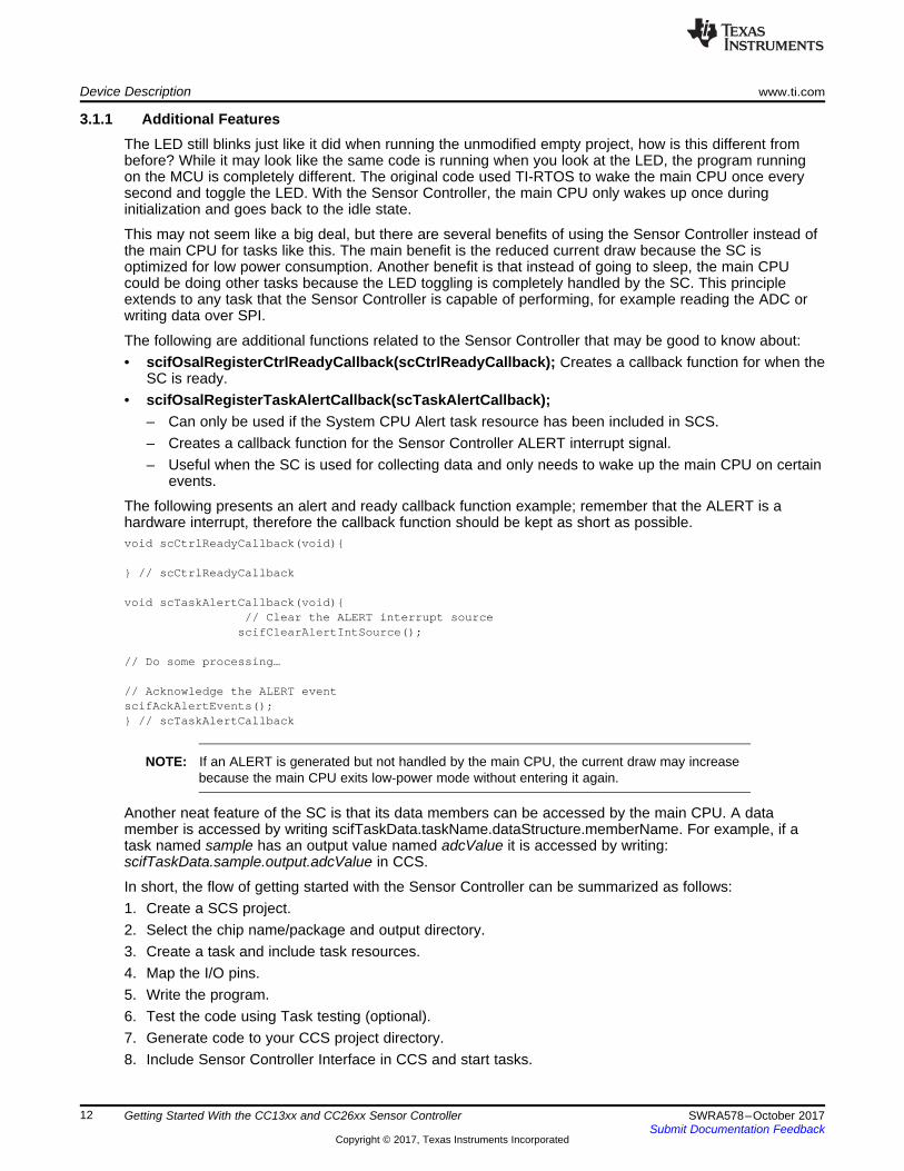
3.1.1 Additional FeaturesThe LED still blinks just like it did when running the unmodified empty project, how is this different frombefore? While it may look like the same code is running when you look at the LED, the program runningon the MCU is completely different. The original code used TI-RTOS to wake the main CPU once everysecond and toggle the LED. With the Sensor Controller, the main CPU only wakes up once duringinitialization and goes back to the idle state.
This may not seem like a big deal, but there are several benefits of using the Sensor Controller instead ofthe main CPU for tasks like this. The main benefit is the reduced current draw because the SC isoptimized for low power consumption. Another benefit is that instead of going to sleep, the main CPUcould be doing other tasks because the LED toggling is completely handled by the SC. This principleextends to any task that the Sensor Controller is capable of performing, for example reading the ADC orwriting data over SPI.
The following are additional functions related to the Sensor Controller that may be good to know about:• scifOsalRegisterCtrlReadyCallback(scCtrlReadyCallback); Creates a callback function for when the
SC is ready.• scifOsalRegisterTaskAlertCallback(scTaskAlertCallback);
– Can only be used if the System CPU Alert task resource has been included in SCS.– Creates a callback function for the Sensor Controller ALERT interrupt signal.– Useful when the SC is used for collecting data and only needs to wake up the main CPU on certain
events.
The following presents an alert and ready callback function example; remember that the ALERT is ahardware interrupt, therefore the callback function should be kept as short as possible.void scCtrlReadyCallback(void){
} // scCtrlReadyCallback
void scTaskAlertCallback(void){// Clear the ALERT interrupt source
scifClearAlertIntSource();
// Do some processing…
// Acknowledge the ALERT eventscifAckAlertEvents();} // scTaskAlertCallback
NOTE: If an ALERT is generated but not handled by the main CPU, the current draw may increasebecause the main CPU exits low-power mode without entering it again.
Another neat feature of the SC is that its data members can be accessed by the main CPU. A datamember is accessed by writing scifTaskData.taskName.dataStructure.memberName. For example, if atask named sample has an output value named adcValue it is accessed by writing:scifTaskData.sample.output.adcValue in CCS.
In short, the flow of getting started with the Sensor Controller can be summarized as follows:1. Create a SCS project.2. Select the chip name/package and output directory.3. Create a task and include task resources.4. Map the I/O pins.5. Write the program.6. Test the code using Task testing (optional).7. Generate code to your CCS project directory.8. Include Sensor Controller Interface in CCS and start tasks.
www.ti.com Performance Comparison
13SWRA578–October 2017Submit Documentation Feedback
Copyright © 2017, Texas Instruments Incorporated
Getting Started With the CC13xx and CC26xx Sensor Controller
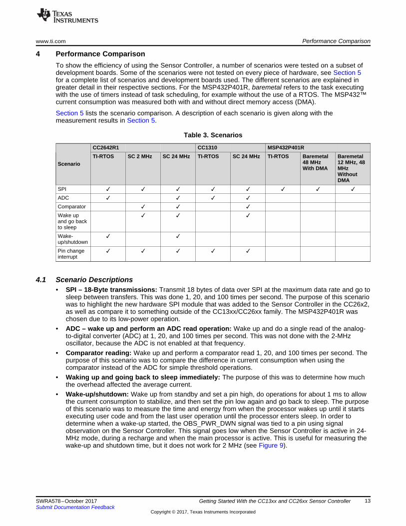
4 Performance ComparisonTo show the efficiency of using the Sensor Controller, a number of scenarios were tested on a subset ofdevelopment boards. Some of the scenarios were not tested on every piece of hardware, see Section 5for a complete list of scenarios and development boards used. The different scenarios are explained ingreater detail in their respective sections. For the MSP432P401R, baremetal refers to the task executingwith the use of timers instead of task scheduling, for example without the use of a RTOS. The MSP432™current consumption was measured both with and without direct memory access (DMA).
Section 5 lists the scenario comparison. A description of each scenario is given along with themeasurement results in Section 5.
Table 3. Scenarios
Scenario
CC2642R1 CC1310 MSP432P401RTI-RTOS SC 2 MHz SC 24 MHz TI-RTOS SC 24 MHz TI-RTOS Baremetal
48 MHzWith DMA
Baremetal12 MHz, 48MHzWithoutDMA
SPI ✓ ✓ ✓ ✓ ✓ ✓ ✓ ✓ADC ✓ ✓ ✓ ✓Comparator ✓ ✓ ✓Wake upand go backto sleep
✓ ✓ ✓
Wake-up/shutdown
✓ ✓
Pin changeinterrupt
✓ ✓ ✓ ✓ ✓
4.1 Scenario Descriptions• SPI – 18-Byte transmissions: Transmit 18 bytes of data over SPI at the maximum data rate and go to
sleep between transfers. This was done 1, 20, and 100 times per second. The purpose of this scenariowas to highlight the new hardware SPI module that was added to the Sensor Controller in the CC26x2,as well as compare it to something outside of the CC13xx/CC26xx family. The MSP432P401R waschosen due to its low-power operation.
• ADC – wake up and perform an ADC read operation: Wake up and do a single read of the analog-to-digital converter (ADC) at 1, 20, and 100 times per second. This was not done with the 2-MHzoscillator, because the ADC is not enabled at that frequency.
• Comparator reading: Wake up and perform a comparator read 1, 20, and 100 times per second. Thepurpose of this scenario was to compare the difference in current consumption when using thecomparator instead of the ADC for simple threshold operations.
• Waking up and going back to sleep immediately: The purpose of this was to determine how muchthe overhead affected the average current.
• Wake-up/shutdown: Wake up from standby and set a pin high, do operations for about 1 ms to allowthe current consumption to stabilize, and then set the pin low again and go back to sleep. The purposeof this scenario was to measure the time and energy from when the processor wakes up until it startsexecuting user code and from the last user operation until the processor enters sleep. In order todetermine when a wake-up started, the OBS_PWR_DWN signal was tied to a pin using signalobservation on the Sensor Controller. This signal goes low when the Sensor Controller is active in 24-MHz mode, during a recharge and when the main processor is active. This is useful for measuring thewake-up and shutdown time, but it does not work for 2 MHz (see Figure 9).

Performance Comparison www.ti.com
14 SWRA578–October 2017Submit Documentation Feedback
Copyright © 2017, Texas Instruments Incorporated
Getting Started With the CC13xx and CC26xx Sensor Controller
Figure 9. OBS_PWR_DWN (Top), Output Pin (Bottom)
• Pin change interrupt: Wake up from a falling edge on a pin and set an output pin high. Wait for 1 msand then set the pin low again, go back to sleep and wait for next interrupt. The wake-up time wasmeasured as the time it took from when the input signal went low until the output went high.
4.1.1 Measurement ConditionsA set of conditions are assumed in order to achieve consistent and reliable measurements that arereplicable. To suppress external interferences, all jumpers were removed from the LaunchPads and theSmartRF06 evaluation board, and short wires were used when connecting to the DC power analyzer.Additionally, the logic analyzer was completely removed when performing current measurements. On theCC1310 board there is a flash memory IC which was also physically removed from the board prior to themeasurements. The flash can be disabled through software and this should render results similar to whenit was completely removed.
The current averages were measured using the Keysight 14585A Control and Analysis Software. Thescope mode was used in single trigger mode, and markers were set from the start of one wake-up untilthe start of the next, as shown in Figure 3. Ten values were collected and averaged. Ensure to set theRange option to auto because the default range, 3A, results in poor resolution and inaccurate results (seeFigure 10).
You can read more about power measurements in the Measuring Bluetooth low energy application note.
Figure 10. First Marker Before Application, Second Marker Before Next Application

www.ti.com Results
15SWRA578–October 2017Submit Documentation Feedback
Copyright © 2017, Texas Instruments Incorporated
Getting Started With the CC13xx and CC26xx Sensor Controller
5 ResultsThe following sections present the results of the comparative measurements between the SensorController Engines and the Cortex CPUs.
5.1 SPI – 18-Byte TransmissionTable 4 lists the average current consumption for 18 byte SPI transmission. As expected, the CC2642R1Sensor Controller has a lower current consumption. The difference is most striking when waking up 100times per second.
Table 4. Average Current Consumption for 18-Byte SPI Transmission: 1, 20, and 100 Times PerSecond
ProcessorConfiguration
SPI Clock Frequency [MHz] Wake-Ups Per Second Units1 time 20 times 100 times
CC2642R1 SC, 2MHz
1 1.0 1.4 3.0 µA
CC2642R1 SC,24 MHz
12 1.5 4.0 15.6 µA
CC2642R1Cortex-M4 runningTI-RTOS
12 2.4 25.4 119.2 µA
CC1310 SC, 24MHz
2 1.1 5.3 22.9 µA
CC1310 Cortex-M3 running TI-RTOS
12 2.6 32.8 158.3 µA
MSP432 runningTI-RTOS
12 2.3 21.5 108.3 µA
MSP432baremetal 48 MHzWith DMA
16 1.2 5.8 26.2 µA
MSP432baremetal 12MHz, 48 MHzWithout DMA
16 1.3 7.4 32.8 µA

Results www.ti.com
16 SWRA578–October 2017Submit Documentation Feedback
Copyright © 2017, Texas Instruments Incorporated
Getting Started With the CC13xx and CC26xx Sensor Controller
Figure 11 shows the current consumption when performing SPI communication.
Figure 11. SPI Current Consumption
Figure 12 shows the current profile for a single SPI transaction.
Figure 12. Current Traces for One Wake-Up of an SPI Application Running on Different Hardware
www.ti.com Results
17SWRA578–October 2017Submit Documentation Feedback
Copyright © 2017, Texas Instruments Incorporated
Getting Started With the CC13xx and CC26xx Sensor Controller
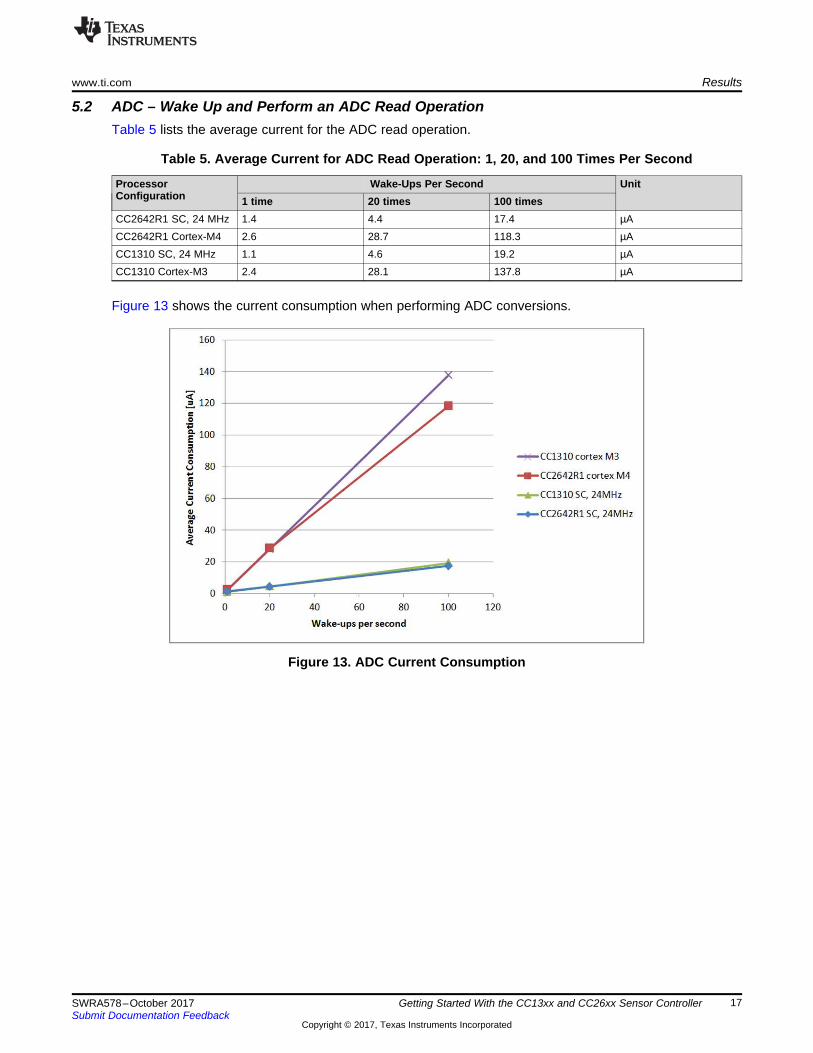
5.2 ADC – Wake Up and Perform an ADC Read OperationTable 5 lists the average current for the ADC read operation.
Table 5. Average Current for ADC Read Operation: 1, 20, and 100 Times Per Second
ProcessorConfiguration
Wake-Ups Per Second Unit1 time 20 times 100 times
CC2642R1 SC, 24 MHz 1.4 4.4 17.4 µACC2642R1 Cortex-M4 2.6 28.7 118.3 µACC1310 SC, 24 MHz 1.1 4.6 19.2 µACC1310 Cortex-M3 2.4 28.1 137.8 µA
Figure 13 shows the current consumption when performing ADC conversions.
Figure 13. ADC Current Consumption

Results www.ti.com
18 SWRA578–October 2017Submit Documentation Feedback
Copyright © 2017, Texas Instruments Incorporated
Getting Started With the CC13xx and CC26xx Sensor Controller
5.3 Comparator ReadingTable 6 lists the average current consumption for a comparator read.
Table 6. Average Current Consumption for Comparator Read: 1, 20, and 100 Times Per Second
ProcessorConfiguration
Wake-Ups Per Second Units1 time 20 times 100 times
CC2642R1 SC, 2 MHz 0.9 1.0 1.5 µACC2642R1 SC, 24 MHz 1.4 3.6 13.6 µACC1310 SC, 24 MHz 2.1 4.0 15.5 µA
Figure 14 shows the current consumption when running the comparator.
Figure 14. Comparator Current Consumption

www.ti.com Results
19SWRA578–October 2017Submit Documentation Feedback
Copyright © 2017, Texas Instruments Incorporated
Getting Started With the CC13xx and CC26xx Sensor Controller
5.4 Waking Up and Returning to Sleep ImmediatelyTable 7 lists the average current for waking up 1, 20, and 100 times per second.
Table 7. Average Current for Waking Up: 1, 20, and 100 Times Per Second
ProcessorConfiguration
Wake-Ups Per Second Units1 time 20 times 100 times
CC2642R1 SC, 2 MHz 1.0 1.0 1.2 µACC2642R1 SC, 24 MHz 1.4 3.4 13.0 µACC1310 SC, 24 MHz 2.2 4.1 15.7 µA
Figure 15 shows the current consumption for SC wake-ups only.
Figure 15. Wake-Up Current Consumption

Results www.ti.com
20 SWRA578–October 2017Submit Documentation Feedback
Copyright © 2017, Texas Instruments Incorporated
Getting Started With the CC13xx and CC26xx Sensor Controller
5.5 Wake-Up and ShutdownTable 8 lists the wake-up and shutdown time and energy for the CC2642R1 M4 and SC.
Table 8. Wake-Up and Shutdown Time and Energy for CC2642R1 M4 and SC
Parameter CC2642R1 Sensor Controller, 24 MHz CC2642R1 M4 Running TI-RTOSWake-up time 143 µs 282.3 µsWake-up energy 82.5 nC 628.1 nCShutdown time 32.6 µs 100.1 µsShutdown energy 14.4 nC 335.1 nC
Figure 16 shows a typical wake-up and shutdown.
Figure 16. Typical Waveform for One Wake-Up and Shutdown, SC (1-ms Active Time)
Figure 17 shows the wake-up and shutdown times and energies.
Figure 17. Wake-Up and Shutdown Time and Energy for SC and Cortex-M4 CPU

www.ti.com Results
21SWRA578–October 2017Submit Documentation Feedback
Copyright © 2017, Texas Instruments Incorporated
Getting Started With the CC13xx and CC26xx Sensor Controller
5.6 Pin Change InterruptFigure 18 shows the wake-up time when reacting to an interrupt for the SC and the Cortex CPUs.
Figure 18. SC and Cortex CPU Interrupt Wake-Up Times

Conclusion www.ti.com
22 SWRA578–October 2017Submit Documentation Feedback
Copyright © 2017, Texas Instruments Incorporated
Getting Started With the CC13xx and CC26xx Sensor Controller
6 ConclusionJudging from the results, the Sensor Controller has significantly lower power consumption compared tothe main CPU in the CC2642R1, and CC1310 and MSP432 when performing data collection fromsensors. However, there are some areas where the main CPU is the better option. Specifically, whenperforming complex mathematical operations and calculations, because the M3 and M4 are better suitedfor such tasks.
There are some interesting use cases for the Sensor Controller that have yet to be discussed in thisapplication note. The first case is a method for further reducing power consumption of a system using theSensor Controller. Usually, sensors do not need to be active constantly since they are usually readperiodically. One way of reducing the power consumption of such an application is to only enable thesensors so that they are stable when the Sensor Controller wakes up to read them. In the CC2642R1Sensor Controller, this can be done using Timer 2 without having to wake up to set the enable pins high.This is especially useful for applications that only poll sensors rarely, because the sensors themselvescontribute to the overall power consumption.
Another use case for the Sensor Controller is to collect data and only wake the main processor for dataprocessing. This use of the Sensor Controller offers two main benefits over using the main CPUexclusively. The first use being that since the Sensor Controller uses less power than the main CPU, thepower used for collecting data is reduced significantly. When the Sensor Controller is done collecting data,it can generate an alert to wake the main CPU for processing the data. The second benefit that may notbe as evident as the first, is that by using the SC to collect the data the main CPU is offloaded and free todo other tasks while the data is being collected. For example, the Sensor Controller can sample an ADCchannel continuously and only wake the main processor when the signal passes a threshold.
The 2-MHz low-power mode in the CC2642R1 Sensor Controller enables even lower power consumptionas well as quicker reaction to pin change interrupts. The trade-off is that some peripherals are notavailable in low-power mode and that the processing speed is slower.
Getting started using the Sensor Controller is easy, all that is required is an appropriate device SDK, aswell as Sensor Controller Studio. For more details on how the Sensor Controller works, see the SensorController Studio examples, help documentation, and user's guide, as well as the SimpleLink Academytraining for the Sensor Controller.
7 References1. Texas Instruments, SimpleLink Academy: Introduction to Sensor Controller Presentation2. Texas Instruments, TI Resource Explorer3. Texas Instruments, Measuring Bluetooth low energy Power Consumption, application report4. Texas Instruments, CC13x0, CC26x0 SimpleLink™ Wireless MCU Technical Reference Manual

IMPORTANT NOTICE FOR TI DESIGN INFORMATION AND RESOURCES
Texas Instruments Incorporated (‘TI”) technical, application or other design advice, services or information, including, but not limited to,reference designs and materials relating to evaluation modules, (collectively, “TI Resources”) are intended to assist designers who aredeveloping applications that incorporate TI products; by downloading, accessing or using any particular TI Resource in any way, you(individually or, if you are acting on behalf of a company, your company) agree to use it solely for this purpose and subject to the terms ofthis Notice.TI’s provision of TI Resources does not expand or otherwise alter TI’s applicable published warranties or warranty disclaimers for TIproducts, and no additional obligations or liabilities arise from TI providing such TI Resources. TI reserves the right to make corrections,enhancements, improvements and other changes to its TI Resources.You understand and agree that you remain responsible for using your independent analysis, evaluation and judgment in designing yourapplications and that you have full and exclusive responsibility to assure the safety of your applications and compliance of your applications(and of all TI products used in or for your applications) with all applicable regulations, laws and other applicable requirements. Yourepresent that, with respect to your applications, you have all the necessary expertise to create and implement safeguards that (1)anticipate dangerous consequences of failures, (2) monitor failures and their consequences, and (3) lessen the likelihood of failures thatmight cause harm and take appropriate actions. You agree that prior to using or distributing any applications that include TI products, youwill thoroughly test such applications and the functionality of such TI products as used in such applications. TI has not conducted anytesting other than that specifically described in the published documentation for a particular TI Resource.You are authorized to use, copy and modify any individual TI Resource only in connection with the development of applications that includethe TI product(s) identified in such TI Resource. NO OTHER LICENSE, EXPRESS OR IMPLIED, BY ESTOPPEL OR OTHERWISE TOANY OTHER TI INTELLECTUAL PROPERTY RIGHT, AND NO LICENSE TO ANY TECHNOLOGY OR INTELLECTUAL PROPERTYRIGHT OF TI OR ANY THIRD PARTY IS GRANTED HEREIN, including but not limited to any patent right, copyright, mask work right, orother intellectual property right relating to any combination, machine, or process in which TI products or services are used. Informationregarding or referencing third-party products or services does not constitute a license to use such products or services, or a warranty orendorsement thereof. Use of TI Resources may require a license from a third party under the patents or other intellectual property of thethird party, or a license from TI under the patents or other intellectual property of TI.TI RESOURCES ARE PROVIDED “AS IS” AND WITH ALL FAULTS. TI DISCLAIMS ALL OTHER WARRANTIES ORREPRESENTATIONS, EXPRESS OR IMPLIED, REGARDING TI RESOURCES OR USE THEREOF, INCLUDING BUT NOT LIMITED TOACCURACY OR COMPLETENESS, TITLE, ANY EPIDEMIC FAILURE WARRANTY AND ANY IMPLIED WARRANTIES OFMERCHANTABILITY, FITNESS FOR A PARTICULAR PURPOSE, AND NON-INFRINGEMENT OF ANY THIRD PARTY INTELLECTUALPROPERTY RIGHTS.TI SHALL NOT BE LIABLE FOR AND SHALL NOT DEFEND OR INDEMNIFY YOU AGAINST ANY CLAIM, INCLUDING BUT NOTLIMITED TO ANY INFRINGEMENT CLAIM THAT RELATES TO OR IS BASED ON ANY COMBINATION OF PRODUCTS EVEN IFDESCRIBED IN TI RESOURCES OR OTHERWISE. IN NO EVENT SHALL TI BE LIABLE FOR ANY ACTUAL, DIRECT, SPECIAL,COLLATERAL, INDIRECT, PUNITIVE, INCIDENTAL, CONSEQUENTIAL OR EXEMPLARY DAMAGES IN CONNECTION WITH ORARISING OUT OF TI RESOURCES OR USE THEREOF, AND REGARDLESS OF WHETHER TI HAS BEEN ADVISED OF THEPOSSIBILITY OF SUCH DAMAGES.You agree to fully indemnify TI and its representatives against any damages, costs, losses, and/or liabilities arising out of your non-compliance with the terms and provisions of this Notice.This Notice applies to TI Resources. Additional terms apply to the use and purchase of certain types of materials, TI products and services.These include; without limitation, TI’s standard terms for semiconductor products http://www.ti.com/sc/docs/stdterms.htm), evaluationmodules, and samples (http://www.ti.com/sc/docs/sampterms.htm).
Mailing Address: Texas Instruments, Post Office Box 655303, Dallas, Texas 75265Copyright © 2017, Texas Instruments Incorporated


![Skaffold - storage.googleapis.com · [getting-started getting-started] Hello world! [getting-started getting-started] Hello world! [getting-started getting-started] Hello world! 5.](https://static.fdocuments.in/doc/165x107/5ec939f2a76a033f091c5ac7/skaffold-getting-started-getting-started-hello-world-getting-started-getting-started.jpg)