Getting Started - · PDF fileThis will undo your last Cadpipe fitting placement. ... Cadpipe...
31
Getting Started Introduction to the Basics Cadpipe Control Center When you first select the Cadpipe Program icon on your desktop, you will automatically start up the Cadpipe Control Center. The Control Center helps you create and organize a directory structure for your projects in a way that all of the Cadpipe modules understand. When you enter for the first time, you will be in the default working project directory created during installation. Of course, you can always just use that, but for this purpose we will assume that you have already created projects within the Industrial 3D Pipe document. All projects created apply to all Cadpipe Industrial modules. If you have already gone through that, you will see a very similar dialog box here.
Transcript of Getting Started - · PDF fileThis will undo your last Cadpipe fitting placement. ... Cadpipe...

Getting Started
Introduction to the Basics
Cadpipe Control Center
When you first select the Cadpipe Program icon on your desktop, you will automatically start up the Cadpipe Control Center. The Control Center helps you create and organize a directory structure for your projects in a way that all of the Cadpipe modules understand. When you enter for the first time, you will be in the default working project directory created during installation. Of course, you can always just use that, but for this purpose we will assume that you have already created projects within the Industrial 3D Pipe document. All projects created apply to all Cadpipe Industrial modules. If you have already gone through that, you will see a very similar dialog box here.

Create a Drawing
Right click within the Drawing area, and you will see the File Operations dialog as shown here.
Select Create.
Enter your Drawing name. For this purpose, we will accept the default prototype drawing, but you can select the Browse Prototypes to choose any that you require. Pick OK, and your drawing will appear in the listing in the control center.
Either double ‘click’ the drawing name, or highlight the drawing name, and select Launch at the bottom of the control center. AutoCAD will open the drawing, and Cadpipe will load.
If you have both metric and imperial Iso installed, you will see the following prompt. Please select your preference. If you only have one of these installed, you won’t see this next dialog box, and will go straight to the next.
See the Available options listed. The Move and Copy options will open a Browse window. Here we will select the Create option.
Enter your required drawing name
Browse to your required prototype drawing, or accept the default iso.dwg (or miso.dwg) in the cpacadw directory

As this is a new drawing, you will have to go through an initialization procedure. This only happens the first time you enter a new uninitialized drawing file. First you will be prompted as to whether or not you would like to initialize the dwg. It is best to agree.
Job numbers entered in this screen can be used for the BOM or for the global bill of materials. In this case, enter anything you’d like, or simply leave that empty, and select OK. We will also leave the scale factor listed at 1, at least for now.
You should see the dialog box below, which confirms that Cadpipe is loaded.
Once Cadpipe is loaded, please set up your AutoCAD screen to your preferences. For example, you may want to dock your toolbars, units of preference etc.
It is a good idea to have your AutoCAD Osnap toolbar docked as well for easy access.

Customizing your setup
You can easily make changes to the way that your isometrics are going to be drawn. While more information on this is readily available through other documentation, a quick look prior to starting your drawing might be a good idea. It is simple to set up to suit your company standards.
You will find this command under the Edit pulldown menu >> Customizing >> Edit Defaults file. You can also access this command from your Utilities Toolbar, or your CP Iso Ribbon tab.
For this purpose, we will simply make one change – to have our piping drawn with a width.
Select Drawing Standards.
Select #8. Plotted Width of Pipe on Drawing, then OK
Make your change – Here we are setting to .03125 (0.8mm)

You will see your change reflected in the listing, select OK, then Update. Your system settings have now been modified for all drawings that you will create – whether manually, or through autoiso.

Commands to Remember
Reset – Located under the Settings pulldown menu, the CP Iso Ribbon Tab, and on the Settings toolbar as shown.
This command will reset all of your applicable current settings to those of a digitized fitting. For example, line designation, size, rating, schedule, etc.
Undo Back – Located under the Edit pulldown menu, All Cadpipe Ribbon Tabs, and on the Settings toolbar as shown. This will undo your last Cadpipe fitting placement.
Erase Fitting – Located under the Edit >> Fittings pulldown menu, the CP Modify Ribbon Tab, or on the Edit toolbar as shown. You can also use the keyboard command EF.
This command will erase a complete fitting with one pick, ensuring that all nodes, tags etc are also removed. You should also use this with Cadpipe dimensions, or the BOM.
Cadpipe Current Settings
Current Settings
This dialog box shows you all of your current settings. That is, all of the parameters that define the pipe or fittings that you are going to place. ie Pipe size, schedule, rating etc. It is available on the Settings toolbar as illustrated, under the Settings pulldown menu, or on the CP ISO ribbon tab.
The first thing that you will want to look at here is the Line Designation. Set your line number to whatever you like. (P-101 used here) Do not include the pipe size in the line number – this will only cause duplication.

Cadpipe comes equipped with many example piping specifications. Obviously, you would set up your own, initially by copying one of our supplied samples and renaming that. For this purpose though, we will set to c12a – which is a supplied, generic 150# CS spec. Further information on customizing piping specs will be discussed later.
For now, set your spec to c12a. You will see a spec check ‘button’. When that is turned on, you will see all the settings below become deactivated. The spec controls the schedules, ratings etc. If you want to change any of these, you can turn spec check off, and it is all activated again.
Set your Spec Alternate button on as well. This will give you options including all items within the spec, rather than the defaults only.
The spec override button disables spec check for one placement, and is also available on the placement dialog boxes. Don’t worry about that one at this time.
For example, with c12a, spec on – change your pipe size from 1” to 6” (25-150mm), and you’ll see the settings in the dialog box change. This spec is SW small bore, and BW 150# large bore.
While it is not required to use piping specs at all, it is recommended. We’ll use c12a in this example, but feel free to use another if you prefer. A brief description of our generic supplied specs follows. All listed use the AP database unless otherwise noted.

For your information....
Summary of Supplied Example Specs : All use the ANSI Plus database unless otherwise noted.
AAA1 300# CS
ABB1 300# CS / THRD Small Bore
C12A 150# CS
C12LJ 150# CS, Lap Joint Flanges
C32A 300# CS
C62A 600# CS
C92A 900# CS
CA2B 1500# CS
CB2B 2500# CS
CL-001 600# Clamped
F-LINED 150# CS Lined
FLGD 150# CS Flanged
FRP1 150# Fibercast (Plastics db)
FRP2 150# FRP Lapped (Plastics db)
PVC 150# PVC (Plastics db)
S11C 150# 304 SS (AP db)
S11D 150# 304L SS (AP db)
S11E 150# 316 SS (AP db)
S11F 150# 316L SS (AP db)
S11LJ 150# 304 SS Lap Joint (SS db)
S31C 300# 304 SS (AP db)
S31D 300# 304L SS (AP db)
S31E 300# 316 SS (AP db)
S31F 300# 316L SS (AP db)
S61C 600# 304 SS (AP db)
S61D 600# 304L SS (AP db)
S61E 600# 316 SS (AP db)
S61F 600# 316L SS (AP db)
Depending on your installation, you may also see supplied example specs from the DIN or BS databases.
Cadpipe Iso gives you the ability to place schematic isometric representations of your equipment. In this instance, we won’t, but you can refer to the Iso Help file for information on how to do that where required.

Routing Line
Cadpipe uses an intelligent 3D polyline, or a routing line, to represent a run of pipe. Items placed on that routing line automatically adopt the intelligence of that routing line. (line number and specification)
Generally, you will draw your routing line with Ortho mode set on, to ensure that your line is at standard isoplane angles. Turn it off when you want to illustrate a roll or offset.
You will find the routing line command on the Cadpipe Place pulldown menu, on the CP ISO Ribbon tab, or on your Place toolbar as shown. Routing lines, as well as all of the information nodes and join points within Cadpipe are all placed on non-plotting layers.
Notice on the command line, that you have the option to set your line designation (line number and spec) during routing line placement, or you can use the Current Settings dialog box. Your current line designation is reflected on the command line.
For this example, layout a simple routing line similar to the one shown below. Use your Transparent IsoPlane settings to change your isoplane where required. Keep your Ortho mode set on in this instance.

Auto Elbow
Once you have your routing line laid out, use the Auto Elbow LR Command to place elbows. You can access the Auto Elbow command under the Cadpipe Auto pulldown menu, the CP ISO Ribbon Tab, or on your Automatic Functions toolbar. (You can also use the shortcut command typing AE at the command line.)
Select Auto Elbow LR, and digitize anywhere on your routing line. Return to complete the entire line. You can select the routing line at any location and return for the entire line, or you could select a start and end point to only place elbows on a section of your line.
It is a good idea to have your AutoCAD Osnap toolbar docked for easy access. You will notice that some of the osnap options come up automatically. In this case ‘Nearest’.
The Status line at the bottom left of your drawing will always let you know what your current settings are (line number, spec, size, and isoplane) Spec is also listed there if your spec check is turned on. Currently you should see:
Place Flange
Now we can place a flange at the 6” end of this particular spool. Flange placement is accessed under the Cadpipe Place pulldown menu, the CP ISO Ribbon Tab, or the Place toolbar as shown.
Notice that as your Spec is ON, that the Face, Rating etc are ‘greyed’ out or deactivated. Also notice the flange orientation icons at the bottom right of your screen. These indicate whether you will be placing the flange by butt or face. Here we will set to face, then Place 1 flange, using the nearest osnap, butt orientated toward your routing line, at each end of our routing line. With your Ortho mode set on, simply drag your cursor to set your outlet orientation.
Command: << <<Place flange>> <6"><150#><Sch STD><Weld Neck><Raised Face>
Digitize face of flange/Insert/ <Exit>:: near
Angle to butt:
Digitize face of flange/Insert/ <Exit>::
.
Here, note the double colon. Anywhere you see that, you can use your transparent isoplanes to select the plane that you want the flange placed in.


Then we will place a reducing tee and a concentric reducer. These commands are available under your CP ISO Ribbon tab, your Place pulldown menu, or on the Place toolbar as shown.
Select 4” (100) for your outlet size, to place a 6x4 (150x100) tee.
You will also select 4” as the outlet of your concentric reducer.

Notice that, after placing the reducer, your current size is re-set from 6” to 4”.
Next, we will place a gate valve.
You’ll find the valve dialog box under the Cadpipe Place pulldown menu, the CP ISO Ribbon Tab, or the Place toolbar as shown.
Notice in the bottom right of the dialog box, that you can set the insertion and configuration of the valve. Ie: 1, 2 or no flanges, and the insertion point. Ensure that you are set to 2 flanges, valve insertion to the flange butt.

Digitize the outlet node of the concentric reducer just placed, to ensure that the valve is placed fitting to fitting. When prompted, drag the handwheel into the required orientation. (up) Watch your command line.
Then place a couple of 4” (100) flanges as shown.

Command: << <<Place flange>> <4"><150#><Sch STD><Weld Neck><Raised Face>
Digitize butt of flange/Insert/ <Exit>:: near to
Angle to face:
Digitize butt of flange/Insert/ <Exit>:: i
Flange insertion point <Flange face>
Digitize face of flange/Insert/ <Exit>:: nod of
Flange Face <Raised Face
Digitize face of flange/Insert/ <Exit>::
Flange Face <Raised Face>
Reset
There is a Reset command located under the Settings pulldown, the CP ISO Ribbon Tab, or on the Settings toolbar as shown. This will reset your current settings to the values of the selected item.
We will also place a flange and a blind flange on the outlet of the reducing tee that was placed earlier. If you had used another line number for the outlet of that reducing tee, select that after selecting Reset.
Notice that you can change the insertion point of the flange on the command line.

Placing Pipe
There are a couple of ways to Place Pipe in Cadpipe Iso. Because this is a schematic drawing, if you want to use the Auto Pipe command, your isometric needs to be fully dimensioned. You can also Place pipe between 2 fittings by typing in the pipe length – with the Place Pipe command. If you want to place a known length of piping, not between 2 fittings, use the place nipple command under the Fittings placement dialog box. A BW nipple will appear in your material list as a cut pipe length.
For example, let place a known pipe length, using the place pipe command. You will find this command under the Place >> Piping pulldown menu, the CP ISO Ribbon Tab, or on the Placement toolbar as shown. You can also use a keyboard command PP.

Iso Dimensioning
The Iso Dimensioning commands are located under the Annotation pulldown, the CP Tools Ribbon Tab, or on the Iso dimensioning toolbar as shown.
Select the Valve Iso Dimensioning command first. Use this option everywhere that you want to account for 1 or 2 gaskets. Here we will use this to dimension from the elbow to the flange face as shown. Because the pipe has been placed, this will behave like a fitting to fitting dimension, not asking you for the value. We will also use this to dimension the other end of the drawing, again from the elbow to the flange fce, but you will be prompted to enter the dimension value – as no pipe has yet been placed. We will enter 5’6 (1675) in this case. You will also be prompted for the dimension line placement location. Notice that you will be prompted to digitize the routing line where no gasket is found, and you are not fitting to fitting.
Use the Iso Dimensioning command to place the other dimensions, using the examples shown if you like. Notice that you will be prompted to digitize the routing line in each instance. Watch your command line.

Auto Pipe
You will find the AutoPipe command under the Auto pulldown menu, the CP Iso Ribbon Tab, or on the Automatic Functions toolbar as shown.
Select AutoPipe, and digitize the routing line – anywhere. All of your pipe lengths will be placed. Pipe that is already placed, such as the one segment that we placed manually, will not be duplicated.
Note: There is a connection node at the dimension arrow tip, that you can use to ensure that your dimensions line up precisely.

AutoBOM
Cadpipe’s Bill of Materials can extract your material list into several different formats, depending on your specific requirements. (ie: excel, access, ascii, display, to printer, or to the drawing.) You can extract material information from a single drawing file, or from an entire project.
Material descriptions and user codes – or part numbers – are read in from your piping specifications, so can be as simple or detailed as you require. More information on this is included in the documentation on Cadpipe Specs.
The Auto BOM command is found on the Cadpipe Tools pulldown, on the CPTools ribbon tab, or on the Reporting toolbar as shown.
Selecting the AutoBOM icon, will bring up the dialog box above.
Use the CDF option to export the BOM into excel.
As here we will simply run a report to our display, select Process BOM in the above dialog box.
As we selected the report, you should see an additional dialog box with reporting options. (sorting, output etc)

Also note that you can include or exclude Revision information, Long descriptions or weight. Here, check Include Long Desc., then OK
In this instance, your BOM will appear on your screen, complete with the material descriptions from your piping specifications.
If you did want to place the material listing on your drawing, notice that the Drawing BOM Sort Order options become available in this first dialog box. A BOM formatting Utility is available on your menu to customize the BOM on the drawing. You will find more information on the formatting utility in subsequent documentation.
Simply selecting Place BOM on Drawing, and the default – Total Pipe – All, will give you something similar to what you see below, on your drawing.

Again, this formatting is easily modified with our BOM to drawing formatting utility. Customization of this format will be discussed in subsequent documentation.

Annotations
North Arrow
While isometrics created through the AutoIso command already have a north arrow placed, manual ones may not. You will find the north arrow under the Place >> Symbols pulldown menu, the CP ISO Ribbon Tab, or on the Symbols toolbar as shown.
Please note that you must be in one of the Top isoplanes to place a north arrow.
Line Label
The Line label will be found under the Annotation pulldown menu, the CP Tools Ribbon Tab, or the Annotation toolbar as shown.
BOM Off
Cadpipe Iso allows you to set the BOM off for selected items. For example, perhaps on continuations for this particular iso. You will find this utility under the Edit pulldown, the CP Tools Ribbon tab, or on the utilities toolbar as shown.
For example, lets change the mating flange on the right of the line drawn. Select the command, and window the continuation flange as shown. You should see that change to an existing layer, and a dashed linetype. Simply re-run the BOM to the drawing – it will be automatically updated to reflect this change.

See editing of dimensions, and ballooning your drawings, following AutoIsos.
AutoIso
If you have previously gone through the Industrial 3D module, you will have created 2 ude (Universal Data Exchange) files from your model. These are the files used to generate isometrics automatically.
If you did not go through the 3D module Getting Started, creating these files, please skip over this section of this document.
Prepare Prototype
First create an empty iso drawing that you want to use as a prototype drawing for your isometrics. Here we will use the default iso template supplied.
So lets create a drawing from the project manager, in this instance we will call it iso prototype. Go through the initialization accepting all defaults, as we did earlier in this document.
Under the Cadpipe Settings pulldown, the CP Tools Ribbon Tab, or the Settings Toolbar as shown, you will find the Cadpipe Prepare Prototype command. You will have to run this command only once – on each prototype drawing that you have.

Watch your command line. When you select the command, you will be asked to digitize the lower left, then upper right of the drawing area. Accept the default scale factor of 1 at this time, and Save the drawing.
Digitize lower left limit of your drawing area::
Digitize upper right limit of your drawing area:
Enter default scale factor <1.0000>:
Save drawing [Yes/No] <Yes>:
Once you have prepared this prototype drawing, you can use it to create as many isometric drawings as required.
The AutoIso command can be found Under the Cadpipe Auto pulldown menu, on the Auto Toolbar or on the CP Tools Ribbon Tab.
Selecting the AutoIso command, as shown, will bring up the following screen. You will see the 2 ude files created in the 3D Design Getting Started module listed on the right. Highlight one, or both of those. (Use your Control or shift key for multiple selections.) Here we will select both.

Please note your options for the isometric generation on the left. For these 2, we will accept the default selections, although you can make any changes that you like.
Select OK after you have highlighted the ude files.
You will then see ‘ghosting’ of the lines chosen. You can modify these as required, or simply return past them.
If you want to, Type R at the command line shown, and change the direction of your North Arrow.

We will return, accepting the default ‘Left’, at the next prompt.
Once you have accepted these, the isos will be generated.
Once the isos have been completed, AutoCAD will exit, and you will be shown a Report of the isos created. Note that these are both stamped complete. An incomplete listed in this report indicates an iso that may have had issues.
Accept OK there, and you will exit AutoCAD and return to the Control Center. Note that there are 2 additional isos there – by the names of the ude files that you had selected. (You may have to refresh your screen, or simply re-select the Iso module.)

Opening either of the new drawing files created should show you something similar to what you see below.
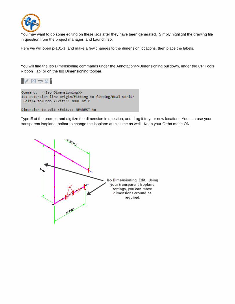
You may want to do some editing on these isos after they have been generated. Simply highlight the drawing file in question from the project manager, and Launch Iso.
Here we will open p-101-1, and make a few changes to the dimension locations, then place the labels.
You will find the Iso Dimensioning commands under the Annotation>>Dimensioning pulldown, under the CP Tools Ribbon Tab, or on the Iso Dimensioning toolbar.
Type E at the prompt, and digitize the dimension in question, and drag it to your new location. You can use your transparent isoplane toolbar to change the isoplane at this time as well. Keep your Ortho mode ON.

Balloons / Labels
Labelling your completed iso is quick and simple. You can do this with any of your isos, manually done, or done through the autoiso command. As long as the bom has been placed on the drawing.
You will find the AutoBalloon command under the Auto pulldown menu, on the CP Tools Ribbon Tab, or on the Auto toolbar as shown.
All of your available options will appear on the command line.
It is easiest to place all your ‘grouped’ balloons prior to running autoballoon.
For example, let’s place a single group for the valve, including both flanges, gaskets and bolts. Then another group for each flange set.
Then do the same for each flange.
Watching your command line, type ‘a’ for AutoBalloon when you have completed the groups. This will label everything that you didn’t initially, and can also be used to update all of your previously placed labels to suit an updated BOM.

Then, again, watching the command line, type E for Edit, M for move, and you can select and move the bubbles to wherever you like.
You should end up with something similar to the view below.

Potential Issues
Note: If, for some reason you do not see this dialog box when you enter the drawing, it is most likely that the Cadpipe module is not loaded. In this case, please confirm that the cp12\cpacadw directory is included in your support file search path within the AutoCAD options command. There are some AutoCAD installations that are not automatically reading the Autodesk switches – particularly if you are using any of the Autodesk Mechanical installations.
Note: If you wish to use the pulldowns, and they do not appear, set menubar to 1 at the command line.