Getting Started and Product Document of Compliance … Getting Started and Product Document of...
16
1 Cisco Systems, Inc. www.cisco.com Getting Started and Product Document of Compliance for the Cisco Wireless Gateway for LoRaWAN First Published: 2016-09-20 Last Updated: 2017-12-21 78-100921-01C0 Cisco Information, page 2 Introduction, page 2 Unpacking the Device, page 2 Equipment That You Supply, page 3 Related Documentation, page 3 Installation Warning and Caution Statements, page 4 Becoming Familiar With the Device, page 5 Power, page 8 Pole/Wall Mounting, page 9 Grounding the Device, page 13 Regulatory Compliance and Safety Information, page 14 For the complete installation procedure, please refer to the Cisco Wireless Gateway for LoRaWAN Hardware Installation Guide on Cisco.com: http://www.cisco.com/c/en/us/support/routers/interface-module-lorawan/products-installation-guides-list.html Important! Read All the Safety Information Before Installing the Hardware.
Transcript of Getting Started and Product Document of Compliance … Getting Started and Product Document of...
Getting Started andProduct Document of Compliance for theCisco Wireless Gateway for LoRaWAN
First Published: 2016-09-20
Last Updated: 2017-12-21
78-100921-01C0
Cisco Information, page 2
Introduction, page 2
Unpacking the Device, page 2
Equipment That You Supply, page 3
Related Documentation, page 3
Installation Warning and Caution Statements, page 4
Becoming Familiar With the Device, page 5
Power, page 8
Pole/Wall Mounting, page 9
Grounding the Device, page 13
Regulatory Compliance and Safety Information, page 14
For the complete installation procedure, please refer to the Cisco Wireless Gateway for LoRaWAN Hardware Installation Guide on Cisco.com:
http://www.cisco.com/c/en/us/support/routers/interface-module-lorawan/products-installation-guides-list.html
Important!
Read All the Safety Information Before Installing the Hardware.
1
Cisco Systems, Inc. www.cisco.com
Getting Started and Product Document of Compliance for the Cisco Wireless Gateway for LoRaWAN
Cisco Information
Cisco Information
IntroductionThe purpose of this document is to provide the installer the necessary information for installing the Cisco Wireless Gateway for LoRaWAN. The documentation is on-line, and subject to change. Make sure that you are downloading or viewing on-line the latest version before beginning an installation:
http://www.cisco.com/c/en/us/support/routers/interface-module-lorawan/products-installation-guides-list.html
Unpacking the DeviceFollow these steps to unpack the box:
1. Open the shipping container and carefully remove the contents.
2. Return all packing materials to the shipping container and save it.
3. Ensure that all items listed in the “Package Contents” section on page 2 are included in the shipment. Check each item for damage. If any item is damaged or missing, notify your authorized Cisco sales representative.
Package Contents
Each Cisco Wireless Gateway for LoRaWAN package contains the following items:
One Cisco Wireless Gateway for LoRaWAN (IXM-LPWA-800-16-K9 or IXM-LPWA-900-16-K9)
This document (Part Number 78-100921-01)
Optional Equipment
Depending on what you ordered, the following optional equipment may be part of your shipment:
Wall/pole mount kit (AIR-ACC1530-PMK1=)
DC-IN power adapter jack plug (PLG-PWRJCK=)
Grounding lug
LoRa Antenna
— Omni-directional antenna (ANT-LPWA-DB-O-N=)
— Antennas lightning arrestor (ACC-LA-H-NM-NF=)
— 10-ft low-loss cable assembly with N type connector (AIR-CAB010LL-N=)
GPS Antenna
— Outdoor GPS antenna with integrated 15-ft cable (ANT-GPS-OUT-TNC=)
Table 1 Cisco Company Name and Address Details
Company Name Cisco Address
Cisco Systems, Inc. 170 West Tasman Drive, San Jose, CA 95134-1706, United States.
2
Getting Started and Product Document of Compliance for the Cisco Wireless Gateway for LoRaWAN
Equipment That You Supply
— Outdoor GPS antenna lightning arrestor (ACC-LA-G-TM-TF=)
Equipment That You Supply ESD-preventive cord and wrist strap.
Crimping tool (such as Thomas & Bett part number WT2000, ERG-2001, or equivalent).
6 AWG (13.3 mm2) copper ground wire
Wire-stripping tools for stripping 6 AWG (13.3 mm2) wire
A number-2 Phillips screwdriver
Related DocumentationTo access resources or to display the latest Cisco Wireless Gateway for LoRaWAN documentation on-line, go to this URL:
www.cisco.com/go/lorawanmodule
This portal has all of the information you need to get to know your device, install and configure it, as well as access software. Look at the right side of the page under Support. You will see the following categories as well as other important information:
All support information for Cisco Wireless Gateway for LoRaWAN: Provides the most requested resources and a list of all of the models in the series.
Software Downloads, Release and General Information: Links to the Software Download site, Compatibility Information, Licensing Information, and Product Release notes.
Install and Upgrade: This is your starting point for Installing the Router. look under the Install and Upgrade Guide section for this model,
Configure: These links provide configuration information. Look first under the Configuration Guide section for this model.
Other important and helpful links to Cisco information are here:
Cisco.com: www.cisco.com
Warranty Information: www.cisco-warrantyfinder.com
Cisco Information Packet, consisting of Cisco Limited Warranty, Disclaimer of Warranty, End User License Agreement, and United States Federal Communications Commission Notice: www.cisco.com/en/US/docs/general/warranty/English/SL3DEN__.html
Cisco Marketplace: marketplace.cisco.com
Cisco Product Documentation: www.cisco.com/go/techdocs
Cisco Support: www.cisco.com/cisco/web/support/index.html
3
Getting Started and Product Document of Compliance for the Cisco Wireless Gateway for LoRaWAN
Installation Warning and Caution Statements
Installation Warning and Caution StatementsWarning: IMPORTANT SAFETY INSTRUCTIONS
Means danger. You are in a situation that could cause bodily injury. Before you work on any equipment, be aware of
the hazards involved with electrical circuitry and be familiar with standard practices for preventing accidents. Use
the statement number provided at the end of each warning to locate its translation in the translated safety warnings
that accompanied this device. Statement 1071
Warning: Before performing any of the following procedures, ensure that power is removed from the DC circuit. Statement 1003
Warning: Read the installation instructions before you connect the system to its power source. Statement 1004
Warning: This product relies on the building’s installation for short-circuit (overcurrent) protection. Ensure that the
protective device is rated not greater than: 2 A. Statement 1005
Warning: This unit is intended for installation in restricted access areas. A restricted access area can be accessed
only through the use of a special tool, lock and key, or other means of security. Statement 1017
Warning: A readily accessible two-poled disconnect device must be incorporated in the fixed wiring.
Statement 1022
Warning: This equipment must be grounded. Never defeat the ground conductor or operate the equipment in the
absence of a suitably installed ground conductor. Contact the appropriate electrical inspection authority or an
electrician if you are uncertain that suitable grounding is available. Statement 1024
Warning: Only trained and qualified personnel should be allowed to install, replace, or service this equipment. Statement 1030
Warning: Ultimate disposal of this product should be handled according to all national laws and regulations. Statement 1040
Warning: For connections outside the building where the equipment is installed, the following ports must be
connected through an approved network termination unit with integral circuit protection: 10/100 Ethernet Statement 1044
Warning: To prevent the system from overheating, do not operate it in an area that exceeds the maximum
recommended ambient temperature of: 131°F (55°C) Statement 1047
Warning: This equipment is intended to be grounded to comply with emission and immunity requirements. Ensure
that the switch functional ground lug is connected to earth ground during normal use. Statement 1064
Warning: Installation of the equipment must comply with local and national electrical codes. Statement 1074
Warning: Avoid using or servicing any equipment that has outdoor connections during an electrical storm. There
may be a risk of electric shock from lightning. Statement 1088
Caution: For the device, connect only to an NEC Class 2 power source or limited power source as defined by IEC
60950-1.
Warning: This product is designed for specific application and needs to be installed by a qualified personal who has
RF and related rule knowledge. The general user shall not attempt to install or change the setting.
Warning: The product shall be installed at a location where the radiating antenna can be kept 34 cm from nearby
person in normal operation condition to meet regulatory RF exposure requirement.
Warning: Use only the antennas which have been approved by the applicant. The non-approved antenna(s) may
produce unwanted spurious or excessive RF transmitting power which may lead to the violation of FCC/ISED limit
and is prohibited.
4
Getting Started and Product Document of Compliance for the Cisco Wireless Gateway for LoRaWAN
Becoming Familiar With the Device
Warning: Please carefully select the installation position and make sure that the final output power does not exceed
the limit set force in relevant rules. The violation of the rule could lead to serious federal penalty.
Note: The device is suitable for use in environmental air space in accordance with section 300.22.C of the National Electrical Code and sections 2-128, 12-010(3), and 12-100 of the Canadian Electrical Code, Part 1, C22.1. You should not install the power supply or power injector in air handling spaces.
Note: Use only with listed ITE equipment.
Note: The maximum ambient operating temperature range is –40 to 131°F (–40 to 55°C), plus solar load.
Note: The POE source which the unit is intended to connect is IEEE 802.3 at.
FCC Caution
Any changes or modifications not expressly approved by the party responsible for compliance could void the user's authority to operate this equipment.
This transmitter must not be co-located or operating in conjunction with any other antenna or transmitter, except the collocation in accordance with FCC multi-transmitter product guidelines.
Industry Canada Statement
This device complies with ISED’s licence-exempt RSSs. Operation is subject to the following two conditions: (1) This device may not cause harmful interference, and (2) this device must accept any interference received, including interference that may cause undesired operation.
Le présent appareil est conforme aux CNR d’ ISED applicables aux appareils radio exempts de licence. L’exploitation est autorisée aux deux conditions suivantes : (1) le dispositif ne doit pas produire de brouillage préjudiciable, et (2) ce dispositif doit accepter tout brouillage reçu, y compris un brouillage susceptible de provoquer un fonctionnement indésirable.
Radiation Exposure Statement
This equipment complies with FCC and ISED radiation exposure limits set forth for an uncontrolled environment. This equipment should be installed and operated with minimum distance 34 cm between the radiator and your body.
Déclaration d'exposition aux radiations
Cet équipement est conforme aux limites d'exposition aux rayonnements ISED établies pour un environnement non contrôlé. Cet équipement doit être installé et utilisé avec un minimum de 34 cm de distance entre la source de rayonnement et votre corps.
Becoming Familiar With the DeviceThe following illustrations show the connections of the Cisco Wireless Gateway for LoRaWAN. Before you begin the installation process, use these illustrations to familiarize yourself with the device.
5
Getting Started and Product Document of Compliance for the Cisco Wireless Gateway for LoRaWAN
Becoming Familiar With the Device
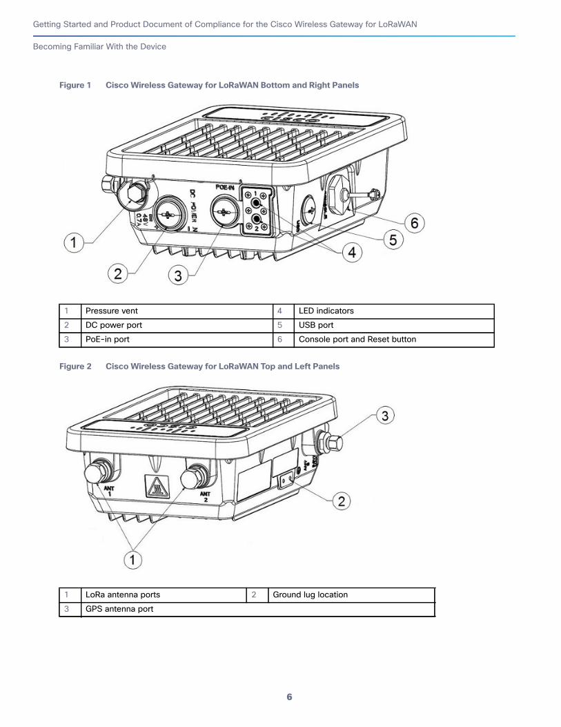
Figure 1 Cisco Wireless Gateway for LoRaWAN Bottom and Right Panels
Figure 2 Cisco Wireless Gateway for LoRaWAN Top and Left Panels
1 Pressure vent 4 LED indicators
2 DC power port 5 USB port
3 PoE-in port 6 Console port and Reset button
1 LoRa antenna ports 2 Ground lug location
3 GPS antenna port
6
Getting Started and Product Document of Compliance for the Cisco Wireless Gateway for LoRaWAN
Becoming Familiar With the Device
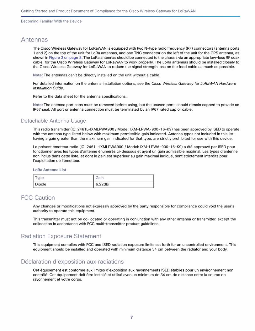
Antennas
The Cisco Wireless Gateway for LoRaWAN is equipped with two N-type radio frequency (RF) connectors (antenna ports 1 and 2) on the top of the unit for LoRa antennas, and one TNC connector on the left of the unit for the GPS antenna, as shown in Figure 3 on page 8. The LoRa antennas should be connected to the chassis via an appropriate low-loss RF coax cable, for the Cisco Wireless Gateway for LoRaWAN to work properly. The LoRa antennas should be installed closely to the Cisco Wireless Gateway for LoRaWAN to reduce the signal strength loss on the feed cable as much as possible.
Note: The antennas can't be directly installed on the unit without a cable.
For detailed information on the antenna installation options, see the Cisco Wireless Gateway for LoRaWAN Hardware Installation Guide.
Refer to the data sheet for the antenna specifications.
Note: The antenna port caps must be removed before using, but the unused ports should remain capped to provide an IP67 seal. All port or antenna connection must be terminated by an IP67 rated cap or cable.
Detachable Antenna Usage
This radio transmitter (IC: 2461L-IXMLPWA900 / Model: IXM-LPWA-900-16-K9) has been approved by ISED to operate with the antenna type listed below with maximum permissible gain indicated. Antenna types not included in this list, having a gain greater than the maximum gain indicated for that type, are strictly prohibited for use with this device.
Le présent émetteur radio (IC: 2461L-IXMLPWA900 / Model: IXM-LPWA-900-16-K9) a été approuvé par ISED pour fonctionner avec les types d'antenne énumérés ci-dessous et ayant un gain admissible maximal. Les types d'antenne non inclus dans cette liste, et dont le gain est supérieur au gain maximal indiqué, sont strictement interdits pour l'exploitation de l'émetteur.
LoRa Antenna List
FCC Caution
Any changes or modifications not expressly approved by the party responsible for compliance could void the user's authority to operate this equipment.
This transmitter must not be co-located or operating in conjunction with any other antenna or transmitter, except the collocation in accordance with FCC multi-transmitter product guidelines.
Radiation Exposure Statement
This equipment complies with FCC and ISED radiation exposure limits set forth for an uncontrolled environment. This equipment should be installed and operated with minimum distance 34 cm between the radiator and your body.
Déclaration d'exposition aux radiations
Cet équipement est conforme aux limites d'exposition aux rayonnements ISED établies pour un environnement non contrôlé. Cet équipement doit être installé et utilisé avec un minimum de 34 cm de distance entre la source de rayonnement et votre corps.
Type Gain
Dipole 6.22dBi
7
Getting Started and Product Document of Compliance for the Cisco Wireless Gateway for LoRaWAN
Becoming Familiar With the Device
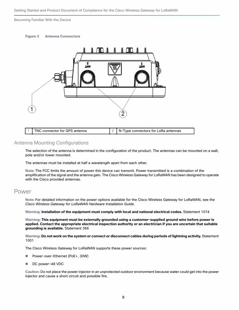
Figure 3 Antenna Connectors
Antenna Mounting Configurations
The selection of the antenna is determined in the configuration of the product. The antennas can be mounted on a wall, pole and/or tower mounted.
The antennas must be installed at half a wavelength apart from each other.
Note: The FCC limits the amount of power this device can transmit. Power transmitted is a combination of the amplification of the signal and the antenna gain. The Cisco Wireless Gateway for LoRaWAN has been designed to operate with the Cisco provided antennas.
Power
Note: For detailed information on the power options available for the Cisco Wireless Gateway for LoRaWAN, see theCisco Wireless Gateway for LoRaWAN Hardware Installation Guide.
Warning: Installation of the equipment must comply with local and national electrical codes. Statement 1074
Warning: This equipment must be externally grounded using a customer-supplied ground wire before power is
applied. Contact the appropriate electrical inspection authority or an electrician if you are uncertain that suitable
grounding is available. Statement 366
Warning: Do not work on the system or connect or disconnect cables during periods of lightning activity. Statement 1001
The Cisco Wireless Gateway for LoRaWAN supports these power sources:
Power-over-Ethernet (PoE+, 30W)
DC power—48 VDC
Caution: Do not place the power injector in an unprotected outdoor environment because water could get into the power injector and cause a short circuit and possible fire.
1 TNC connector for GPS antenna 2 N-Type connectors for LoRa antennas
8
Getting Started and Product Document of Compliance for the Cisco Wireless Gateway for LoRaWAN
Pole/Wall Mounting
Warning: Connect the unit only to DC power source that complies with the Safety Extra-Low Voltage (SELV)
requirements in IEC 60950 based safety standards Statement 1033
Ethernet (PoE+) Ports
The Cisco Wireless Gateway for LoRaWAN supports an Ethernet uplink port (PoE-In). The RJ-45 connector (with weatherproofing) links the device to the 10BASE-T or 100BASE-T network. The Ethernet cable is used to send and receive Ethernet data and to optionally supply inline 56-VDC power from the power injector.
Warning: To reduce the risk of fire, use only No. 26 AWG or larger telecommunication line cord. Statement 1023
The Ethernet cable must be a shielded outdoor rated Category 5 (CAT5) or better cable. The Cisco Wireless Gateway for LoRaWAN senses the Ethernet and power signals and automatically switches internal circuitry to match the cable connections.
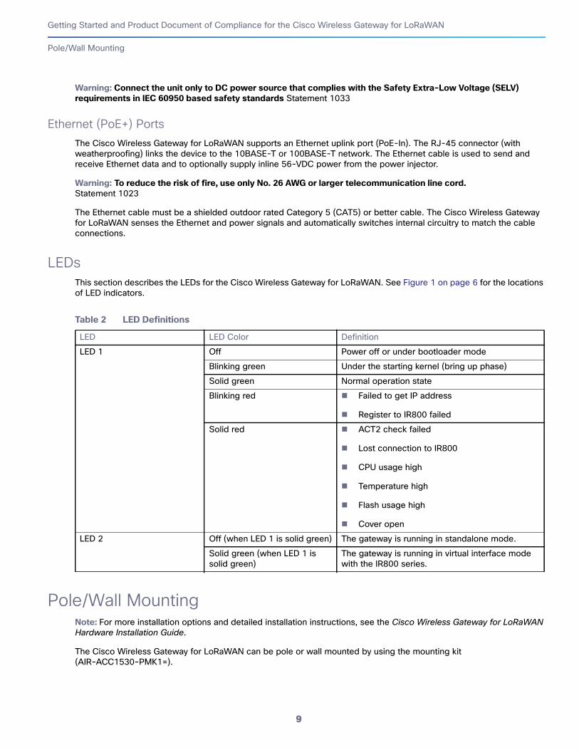
LEDs
This section describes the LEDs for the Cisco Wireless Gateway for LoRaWAN. See Figure 1 on page 6 for the locations of LED indicators.
Pole/Wall MountingNote: For more installation options and detailed installation instructions, see the Cisco Wireless Gateway for LoRaWAN Hardware Installation Guide.
The Cisco Wireless Gateway for LoRaWAN can be pole or wall mounted by using the mounting kit (AIR-ACC1530-PMK1=).
Table 2 LED Definitions
LED LED Color Definition
LED 1 Off Power off or under bootloader mode
Blinking green Under the starting kernel (bring up phase)
Solid green Normal operation state
Blinking red Failed to get IP address
Register to IR800 failed
Solid red ACT2 check failed
Lost connection to IR800
CPU usage high
Temperature high
Flash usage high
Cover open
LED 2 Off (when LED 1 is solid green) The gateway is running in standalone mode.
Solid green (when LED 1 is solid green)
The gateway is running in virtual interface mode with the IR800 series.
9
Getting Started and Product Document of Compliance for the Cisco Wireless Gateway for LoRaWAN
Pole/Wall Mounting
Warning: Only trained and qualified personnel should be allowed to install, replace, or service this equipment. Statement 1030
Warning: Installation of the equipment must comply with local and national electric codes. Statement 1074
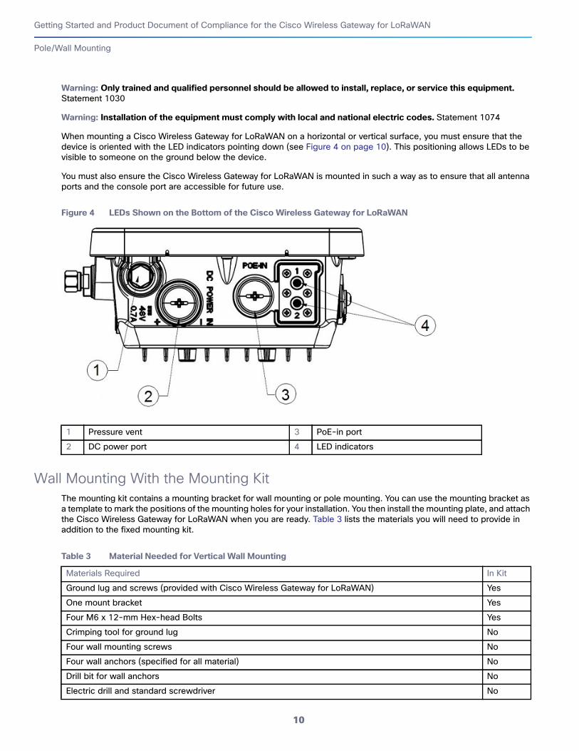
When mounting a Cisco Wireless Gateway for LoRaWAN on a horizontal or vertical surface, you must ensure that the device is oriented with the LED indicators pointing down (see Figure 4 on page 10). This positioning allows LEDs to be visible to someone on the ground below the device.
You must also ensure the Cisco Wireless Gateway for LoRaWAN is mounted in such a way as to ensure that all antenna ports and the console port are accessible for future use.
Figure 4 LEDs Shown on the Bottom of the Cisco Wireless Gateway for LoRaWAN
Wall Mounting With the Mounting Kit
The mounting kit contains a mounting bracket for wall mounting or pole mounting. You can use the mounting bracket as a template to mark the positions of the mounting holes for your installation. You then install the mounting plate, and attach the Cisco Wireless Gateway for LoRaWAN when you are ready. Table 3 lists the materials you will need to provide in addition to the fixed mounting kit.
1 Pressure vent 3 PoE-in port
2 DC power port 4 LED indicators
Table 3 Material Needed for Vertical Wall Mounting
Materials Required In Kit
Ground lug and screws (provided with Cisco Wireless Gateway for LoRaWAN) Yes
One mount bracket Yes
Four M6 x 12-mm Hex-head Bolts Yes
Crimping tool for ground lug No
Four wall mounting screws No
Four wall anchors (specified for all material) No
Drill bit for wall anchors No
Electric drill and standard screwdriver No
10
Getting Started and Product Document of Compliance for the Cisco Wireless Gateway for LoRaWAN
Pole/Wall Mounting
Note: The mounting surface, attaching screws and optional wall anchors must be able to support a 50-lb (22.7 kg) static weight.
To mount the Cisco Wireless Gateway for LoRaWAN on a vertical wall, follow these instructions:
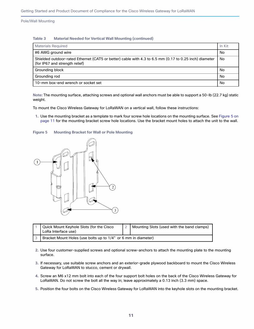
1. Use the mounting bracket as a template to mark four screw hole locations on the mounting surface. See Figure 5 on page 11 for the mounting bracket screw hole locations. Use the bracket mount holes to attach the unit to the wall.
Figure 5 Mounting Bracket for Wall or Pole Mounting
2. Use four customer-supplied screws and optional screw-anchors to attach the mounting plate to the mounting surface.
3. If necessary, use suitable screw anchors and an exterior-grade plywood backboard to mount the Cisco Wireless Gateway for LoRaWAN to stucco, cement or drywall.
4. Screw an M6 x12 mm bolt into each of the four support bolt holes on the back of the Cisco Wireless Gateway for LoRaWAN. Do not screw the bolt all the way in; leave approximately a 0.13 inch (3.3 mm) space.
5. Position the four bolts on the Cisco Wireless Gateway for LoRaWAN into the keyhole slots on the mounting bracket.
#6 AWG ground wire No
Shielded outdoor-rated Ethernet (CAT5 or better) cable with 4.3 to 6.5 mm (0.17 to 0.25 inch) diameter (for IP67 and strength relief)
No
Grounding block No
Grounding rod No
10-mm box-end wrench or socket set No
1 Quick Mount Keyhole Slots (for the Cisco LoRa Interface use)
2 Mounting Slots (used with the band clamps)
3 Bracket Mount Holes (use bolts up to 1/4" or 6 mm in diameter)
Table 3 Material Needed for Vertical Wall Mounting (continued)
Materials Required In Kit
11
Getting Started and Product Document of Compliance for the Cisco Wireless Gateway for LoRaWAN
Pole/Wall Mounting
6. Slide the Cisco Wireless Gateway for LoRaWAN down to sit securely in the quick mount slots.
7. Using a 10mm wrench, secure the Cisco Wireless Gateway for LoRaWAN to the bracket by tightening the bolts to the bracket; torque to 40 in-lbs (4.52 N-m).
8. Continue with Grounding the Device, page 13.
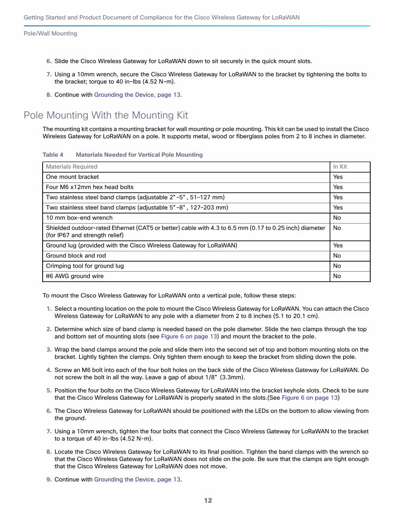
Pole Mounting With the Mounting Kit
The mounting kit contains a mounting bracket for wall mounting or pole mounting. This kit can be used to install the Cisco Wireless Gateway for LoRaWAN on a pole. It supports metal, wood or fiberglass poles from 2 to 8 inches in diameter.
To mount the Cisco Wireless Gateway for LoRaWAN onto a vertical pole, follow these steps:
1. Select a mounting location on the pole to mount the Cisco Wireless Gateway for LoRaWAN. You can attach the Cisco Wireless Gateway for LoRaWAN to any pole with a diameter from 2 to 8 inches (5.1 to 20.1 cm).
2. Determine which size of band clamp is needed based on the pole diameter. Slide the two clamps through the top and bottom set of mounting slots (see Figure 6 on page 13) and mount the bracket to the pole.
3. Wrap the band clamps around the pole and slide them into the second set of top and bottom mounting slots on the bracket. Lightly tighten the clamps. Only tighten them enough to keep the bracket from sliding down the pole.
4. Screw an M6 bolt into each of the four bolt holes on the back side of the Cisco Wireless Gateway for LoRaWAN. Do not screw the bolt in all the way. Leave a gap of about 1/8" (3.3mm).
5. Position the four bolts on the Cisco Wireless Gateway for LoRaWAN into the bracket keyhole slots. Check to be sure that the Cisco Wireless Gateway for LoRaWAN is properly seated in the slots.(See Figure 6 on page 13)
6. The Cisco Wireless Gateway for LoRaWAN should be positioned with the LEDs on the bottom to allow viewing from the ground.
7. Using a 10mm wrench, tighten the four bolts that connect the Cisco Wireless Gateway for LoRaWAN to the bracket to a torque of 40 in-lbs (4.52 N-m).
8. Locate the Cisco Wireless Gateway for LoRaWAN to its final position. Tighten the band clamps with the wrench so that the Cisco Wireless Gateway for LoRaWAN does not slide on the pole. Be sure that the clamps are tight enough that the Cisco Wireless Gateway for LoRaWAN does not move.
9. Continue with Grounding the Device, page 13.
Table 4 Materials Needed for Vertical Pole Mounting
Materials Required In Kit
One mount bracket Yes
Four M6 x12mm hex head bolts Yes
Two stainless steel band clamps (adjustable 2"–5", 51–127 mm) Yes
Two stainless steel band clamps (adjustable 5"–8", 127–203 mm) Yes
10 mm box-end wrench No
Shielded outdoor-rated Ethernet (CAT5 or better) cable with 4.3 to 6.5 mm (0.17 to 0.25 inch) diameter (for IP67 and strength relief)
No
Ground lug (provided with the Cisco Wireless Gateway for LoRaWAN) Yes
Ground block and rod No
Crimping tool for ground lug No
#6 AWG ground wire No
12
Getting Started and Product Document of Compliance for the Cisco Wireless Gateway for LoRaWAN
Grounding the Device
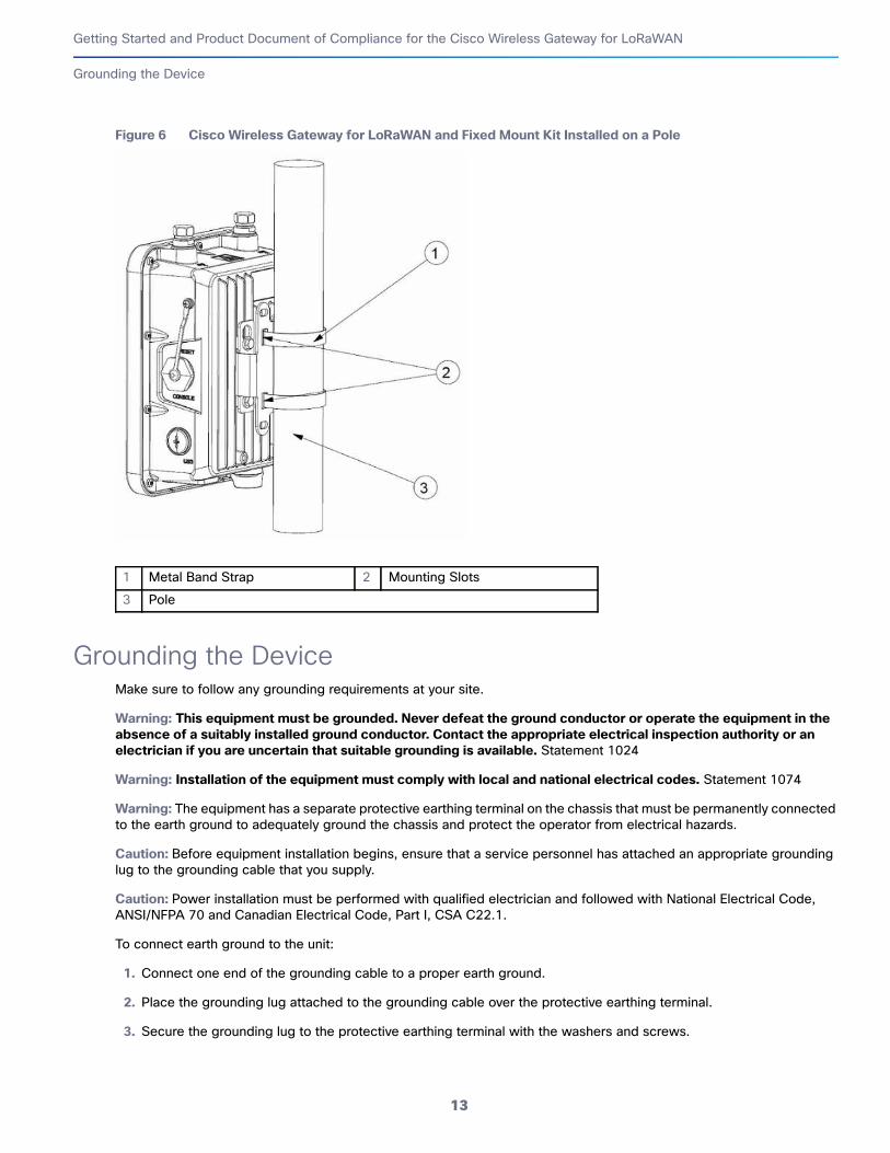
Figure 6 Cisco Wireless Gateway for LoRaWAN and Fixed Mount Kit Installed on a Pole
Grounding the DeviceMake sure to follow any grounding requirements at your site.
Warning: This equipment must be grounded. Never defeat the ground conductor or operate the equipment in the
absence of a suitably installed ground conductor. Contact the appropriate electrical inspection authority or an
electrician if you are uncertain that suitable grounding is available. Statement 1024
Warning: Installation of the equipment must comply with local and national electrical codes. Statement 1074
Warning: The equipment has a separate protective earthing terminal on the chassis that must be permanently connected to the earth ground to adequately ground the chassis and protect the operator from electrical hazards.
Caution: Before equipment installation begins, ensure that a service personnel has attached an appropriate grounding lug to the grounding cable that you supply.
Caution: Power installation must be performed with qualified electrician and followed with National Electrical Code, ANSI/NFPA 70 and Canadian Electrical Code, Part I, CSA C22.1.
To connect earth ground to the unit:
1. Connect one end of the grounding cable to a proper earth ground.
2. Place the grounding lug attached to the grounding cable over the protective earthing terminal.
3. Secure the grounding lug to the protective earthing terminal with the washers and screws.
1 Metal Band Strap 2 Mounting Slots
3 Pole
13

Getting Started and Product Document of Compliance for the Cisco Wireless Gateway for LoRaWAN
Regulatory Compliance and Safety Information
4. Dress the grounding cable and ensure that it does not touch or block access to other components.
Warning: Before the device is powered on, connect the frame of the unit to the earth.
Warning: For the earthing wire, green-and-yellow insulation is required and the cross-sectional area of the conductor must be more than 0.75mm2 or 26 AWG.
Warning: The product shall be installed by a qualified service person and the installation shall conform to all local codes.
Regulatory Compliance and Safety InformationThis product has not obtained the authentication of Japan terminal equipment technical (TBL) standards.
Declarations of Conformity and Regulatory Information
For the declarations of conformity and regulatory information for the Cisco Wireless Gateway for LoRaWAN, see the Cisco Wireless Gateway for LoRaWAN Hardware Installation Guide.
For EMC and safety information, see the Regulatory Compliance and Safety Information at this URL:
http://www.cisco.com/go/lorawanmodule
Compliance Information
Class A Notice for FCC
Modifying the equipment without Cisco’s authorization may result in the equipment no longer complying with FCC requirements for Class A digital devices. In that event, your right to use the equipment may be limited by FCC regulations, and you may be required to correct any interference to radio or television communications at your own expense.
This equipment has been tested and found to comply with the limits for a Class A digital device, pursuant to Part 15 of the FCC Rules. These limits are designed to provide reasonable protection against harmful interference when the equipment is operated in a commercial environment. This equipment generates, uses, and can radiate radio frequency energy and, if not installed and used in accordance with the instruction manual, may cause harmful interference to radio communications. Operation of this equipment in a residential area is likely to cause harmful interference in which case users will be required to correct the interference at their own expense.
Specification Description
Safety IEC 60950-1EN 60950-1UL 60950-1EN 60950-22EN 50385IEC/EN 60529
EMC Electromagnetic Emissions FCC 47 CFR Part 15 Class AEN 55022 Class AVCCI-A
Electromagnetic Immunity EN 55024EN 301 489-1/-3
Radio EN 300 220-2EN 300 440-2
14
Getting Started and Product Document of Compliance for the Cisco Wireless Gateway for LoRaWAN
Regulatory Compliance and Safety Information
EMC Class A Notices and Warnings
Statement 340—Class A Warning for CISPR22
Statement 191—VCCI Class A Warning for Japan
Warnung Dies ist ein Produkt der Klasse A. Bei der Verwendung dieses Produkts im Haus- oder Wohnungsbereichkann es zu Funkstörungen kommen. In diesem Fall muss der Benutzer u. U. angemessene Maßnahmenergreifen.
Warning This is a Class A product based on the standard of the Voluntary Control Council for Interferenceby Information Technology Equipment (VCCI). If this equipment is used in a domesticenvironment, radio disturbance may arise. When such trouble occurs, the user may be requiredto take corrective actions.
15
Getting Started and Product Document of Compliance for the Cisco Wireless Gateway for LoRaWAN
Regulatory Compliance and Safety Information
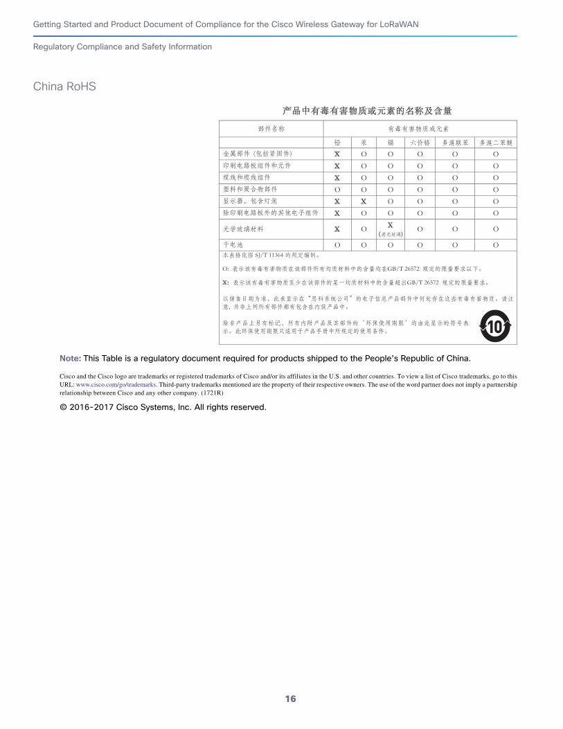
China RoHS
Note: This Table is a regulatory document required for products shipped to the People’s Republic of China.
Cisco and the Cisco logo are trademarks or registered trademarks of Cisco and/or its affiliates in the U.S. and other countries. To view a list of Cisco trademarks, go to thisURL: www.cisco.com/go/trademarks. Third-party trademarks mentioned are the property of their respective owners. The use of the word partner does not imply a partnershiprelationship between Cisco and any other company. (1721R)
© 2016-2017 Cisco Systems, Inc. All rights reserved.
16