
Gestion complexe d’une contamination des sols par du … · Previous end of thermal desorption...
31
Gestion complexe d’une contamination des sols par du mercure au droit d’un site sensible Complex remediation management of mercury soil contamination on a sensitive site BIOGENIE EUROPE : Jérémie LEPLAT ‐ Julien CHIBLEUR HAEMERS TECHNOLOGIES : Jan HAEMERS ‐ Aurélien VANDEKERCKHOVE
-
Upload
duongxuyen -
Category
Documents
-
view
216 -
download
0
Transcript of Gestion complexe d’une contamination des sols par du … · Previous end of thermal desorption...
Gestion complexe d’une contamination des sols par du mercure
au droit d’un site sensible
Complex remediation management of mercury soil contamination on a
sensitive site
BIOGENIE EUROPE : Jérémie LEPLAT ‐ Julien CHIBLEUR
HAEMERS TECHNOLOGIES : Jan HAEMERS ‐ Aurélien VANDEKERCKHOVE

Contents
Crédit photos : © Inventaire général, ADAGP
1. Contexte d’intervention – Site sensible / Sensitive site context
2. Gestion des sols pollués accessibles par terrassement et gestionmultifilière / Off site soil disposal for accessible materials
3. Essais pilotes préalables / Pilot trial ‐ Design
4. Traitement sur site / in situ par désorption thermique et / InSitu‐ Ex Situ Thermal desorption
5. Monitoring and results
6. Conclusions

1. Context / sensitive site

Site Context
End of activity
Buildings demolition
Earthwork excavation for Sensitive building(basement, foundation…)
Volatile mercury concentration over ambiant airquality criteria (up to 12 µg/m3) in the futurecourtyard
Site complementary studies, remediationsolution evaluation
1985
2010
2013
May2015
May2015 March 2016
Old former company (lights company) – South of Paris
Crédit photos : © Inventaire général, ADAGP

Site Contest
Thermal desorption cinetic bench test with mercury speciation.Other studies and analysis (SEMOFI)
First earthwork phase with off site disposal for specific remediation.
Second earthwork phase
Thermal Remediation mobilization (drillings, setup…)
Remediation ignition (successive area loaded)
Previous end of thermal desorption – Final monitoring, Sampling andanalysis : « Agence Régionale de Santé » advice
Winter2015
May 2016
Nov. 2016
June2017
Nov. 2017
Summer2018

Project team

2. Earthwork remediationphases with several off-
sites disposals

Earthwork phases :‐ excavation, on site storage and sampling‐ Loading and off site disposal
80 % Non Hazardous (ISDND) 10 % Hazardous (ISDD) 10 % Stabilization Hazardous (ISDD Stab.)
Free phase collect‐ Mercury Drops and puddles Difficulties for collect
and segregation About 2 liters of free phase (25kg) About 2 m3 of soil mixed with drops sent to valorization site
Earthworksand collect
PHASE SCHEDULE QUANTITIES
PHASE 1 June‐Oct 2016 6.500 t
PHASE 2 Nov 2016 – today 16.700 t

Dense residential area Under Building earthwork
Electricity concrete pipe protection225.000 V
Specific operations

Sensitive excavation – low cadencies
Network electricity … protection
Earthwork close to cheminey
Specific operations
3. Thermal desorption –Essais pilotes / Pilot Trial

Definitions / goals• ESTD / ISTD : volatilizing the polluting compounds by thermal and recovering of the pollutants
volatilized with on‐site treatement• Thermal treatment known and proven for managing high concentrations (source zones) but need to be
adapted to local restrictions :‐ Existing buildings, networks, etc.‐ Hg concentrations on residual crude although more volatile
ISTD and ESTDThermal Desorption On site
Objectives: To eliminate any risk of volatil Hg°and/or unstable HgCl2 compounds

Feedback from experiences:
Thermal desorption kinetics tests with speciation analysis
T = 100 to 260°C over 12 to 168h
On‐site/In situthermal desorption

Results:
• Metal mercury disappears at 150°C;• Most species disappear (HgCl2 and Hg linked to organic matter) at 240°C; • Residual form present in the samples: HgS (mercury sulphide)
Thermal desorption efficiency on tested samples Allows to eliminate the mobile forms of Hg (Hg°, HgCl2)
On‐site/In situthermal desorption
4. ISTD / ESTDThe project
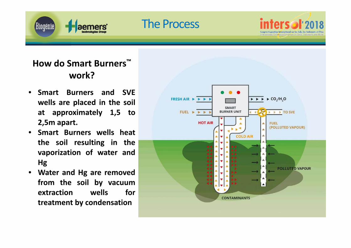
How do Smart Burners™work?
• Smart Burners and SVEwells are placed in the soilat approximately 1,5 to2,5m apart.
• Smart Burners wells heatthe soil resulting in thevaporization of water andHg
• Water and Hg are removedfrom the soil by vacuumextraction wells fortreatment by condensation
The Process

Heating the soil
The heating elements are placed in a triangular pattern.
Heating time vs interdistance
Heating mechanisms
Heat transfer is based on conduction
• Provides a constant radius of action (homogeneity)
• Predictable treatment time for the whole area
• Adapted geometries for specific projects/site
configurations
• Pipe length can be variable and adapted to the depth
of the contamination
Advantages of conduction:
• Almost not influenced by soil heterogeneity
• Predictable heating/transfer time
• Whole mass is treated (no rebound)
• Can treat all types of soil
Vapour tube Heating tube
haemers‐technologies.com
Remediation mechanisms

Design –Horizontal Drilling
41 horizontal drillings – 15 m long with 41 Smart Burners

Vertical Drilling
165 vertical heating tubes (2,9m belowground level into the basement)
90 vertical heating tubes (1,6m belowground level into the excavated areas under building)


Vapor treatment
Condensation / Activated Carbon adsorption

Water treatment
• Thermal desorption required low water moisture and no water table • Project required dewatering (about 1 m dewatering) • Dewatering system 265 m3/h with 14 boreholes (Pumping)• Treatment plant with 8 activated carbon tower + 4 resin vessel tower
• Ponctual storage capacity for process water (from SVE DT plant) : 4 tanks of 70 m3

5. Monitoring / Results

Processmonitoring
BIOGENIE HAEMERS Monitoring :
‐ Temperatures : 2700 thermocouples‐ Control of pressure, flowrates…‐ Combustion gaz control (Nox, SO2, CO…)
‐ Discharge effluent control of water and gaz :direct mesuring with Jérôme and Lumex
‐ Gas Sampling on AC tubes (weekly)‐ Water sampling water tank (one/tank)
‐ Dust control analysis on Owen Jauge (quaterly)
‐ Total mass recovery calculation
Initial quantification between 91 – 250 kg of Hg

Monitoring –T°C
Temperatures monitoring (Thermographies) – 3 Areas controlled
• 9 thermography/day (zone A) + 15 Th/day (zone B/C) + 9 Th/day (zone D)• About 33 Thermography/day to foillow T° evolution

Efficiency results
‐ Average Hg Total recovery / dayabout 2 kg/d recovered
‐ More than 15 kg of total mercuryvaporized and collected sorbed onactivated carbon
‐ Expected free liquid phase condensedin the piping and knockout : > 150 kg soabout 10 liters

Monitoring
ON‐SITE ‐Monitoring (assumed by Maître d’Œuvre – Consultant SEMOFI)‐ Continual LUMEX measurement‐ Water discharge control (daily)‐ Air sampling with hopkalite tube and passive badge
OUTSIDE – Air quality Monitoring (SEMOFI)‐ Daily monitoring with LUMEX
Employees Monitoring‐ Medical exposure monitoring due to high toxicity

6. Conclusions

Conclusions
Complex management of mercury on‐site implies :
Specific approach and multi technologies of earthwork
Specific waste management
Thermal desorption in process : free phase collected
High monitoring required
Pour aller plus loin : snowmannetwork.com (ImaHg) ; rapports BRGM ; INERIS…
15.000 m3
excavated
2.500 m3
treated by ISTD
Free Phase recovery
270 m3 ESTD
2.700 Thermocouples
265 m3/h water discharge

http://www.biogenie‐europe.fr/
BIOGENIE EUROPEChemin de Braseux, Echarcon, France
www.biogenie‐europe.fr | tél : +33 1 64 56 78 00
HAEMERSTechnologies104 Chaussée de Vilvorde, 1120 Brussels ‐ Belgium
haemers‐technologies.com | tél : +32 2 219 13 42


![[MS-ISTD]: iSCSI Software Target Discovery ProtocolMS-ISTD].pdf · iSCSI Software Target Discovery Protocol ... [MS-ISTD]: iSCSI Software Target Discovery Protocol ... The component](https://static.fdocuments.in/doc/165x107/5aa8c7067f8b9a9a188c0144/ms-istd-iscsi-software-target-discovery-protocol-ms-istdpdfiscsi-software-target.jpg)