German WW2 ECM - North Shore Amateur Radio · PDF file17 October 2013 NSARC – German WW2...
34
- • - • - - • - - • • • • • • - • - - • • • - • • • • • - • NSARC – German WW2 ECM 1 17 October 2013 German WW2 ECM German WW2 ECM (Electronic Countermeasures) (Electronic Countermeasures) Adam Farson Adam Farson VA7OJ VA7OJ
Transcript of German WW2 ECM - North Shore Amateur Radio · PDF file17 October 2013 NSARC – German WW2...

- • - • - - • - - • • • • • • - • - - • • • - • • • • • - •
NSARC – German WW2 ECM 1 17 October 2013
German WW2 ECMGerman WW2 ECM
(Electronic Countermeasures)(Electronic Countermeasures)
Adam FarsonAdam Farson
VA7OJVA7OJ

- • - • - - • - - • • • • • • - • - - • • • - • • • • • - •
NSARC – German WW2 ECM 2 17 October 2013
Glossary of termsGlossary of terms
Common acronyms:Common acronyms: SIGINT: SIGINT: SIGSIGnals nals INTINTelligenceelligence
COMINT: COMINT: COMCOMmunicationsmunications INTINTelligenceelligence (communications between people or (communications between people or entities)entities)
ELINT: ELINT: ELELectronicsectronics INTINTelligenceelligence (electronic signals not directly used in (electronic signals not directly used in communications e.g. radar, radiocommunications e.g. radar, radio--navigation)navigation)
ECM: ECM: EElectronic lectronic CCounterounterMMeasureseasures
ECCM: ECCM: EElectronic lectronic CCounterounter--CCounterounterMMeasureseasures
EW: EW: EElectronic lectronic WWarfare (encompasses all the above)arfare (encompasses all the above)
System designators:System designators: AI: AI: AAirborne irborne IInterception radarnterception radar
ASV: ASV: AAir to ir to SSurface urface VVessel radaressel radar
CD: CD: CCoastal oastal DDefence radarefence radar
CH: CH: CChain hain HHome radar (CHL = ome radar (CHL = CChain hain HHome ome LLow)ow)
D/F: D/F: DDirection irection FFindinginding
HuffHuff--Duff: Duff: HHigh igh FFrequency requency D/FD/F
HH22S: British 3 GHz radar with PPI (planS: British 3 GHz radar with PPI (plan--position indicator) displayposition indicator) display (possible (possible abbreviation for abbreviation for ““Home Sweet HomeHome Sweet Home””))
HH22X: US 10 GHz variant of HX: US 10 GHz variant of H22SS

- • - • - - • - - • • • • • • - • - - • • • - • • • • • - •
NSARC – German WW2 ECM 3 17 October 2013
Scope of presentationScope of presentation
Detection, interception & analysisDetection, interception & analysis Communications vs. radar monitoringCommunications vs. radar monitoring
DirectionDirection--findingfinding
Examples of COMINT, ELINT, Examples of COMINT, ELINT, SIGINTSIGINT sitessites
Radar detectionRadar detection VHF/UHF & microwave radar detectors & threat receiversVHF/UHF & microwave radar detectors & threat receivers
Land, shipboard & airborne systemsLand, shipboard & airborne systems
Notes on German microwave technologyNotes on German microwave technology
Jamming & spoofing:Jamming & spoofing: Radio communications: HF, VHF Radio communications: HF, VHF
NavaidsNavaids: GEE, OBOE: GEE, OBOE
Radar: VHF/UHF, 3 GHz, 10 GHzRadar: VHF/UHF, 3 GHz, 10 GHz
Equipment examplesEquipment examples
A case A case historyhistory: Operation Channel Dash : Operation Channel Dash (Cerberus)(Cerberus)

- • - • - - • - - • • • • • • - • - - • • • - • • • • • - •
NSARC – German WW2 ECM 4 17 October 2013
COMINT/ELINT/SIGINTCOMINT/ELINT/SIGINT
Communications monitoringCommunications monitoring HF and VHF land, sea and air radio interceptionHF and VHF land, sea and air radio interception
Decryption; content analysis, distribution to client agenciesDecryption; content analysis, distribution to client agencies
Analysis of signals and equipment signaturesAnalysis of signals and equipment signatures
Radar monitoringRadar monitoring Signal evaluation; pulse rate, spectral & signature analysisSignal evaluation; pulse rate, spectral & signature analysis
Location of fixed radar sitesLocation of fixed radar sites
Identification of land, sea and airborne radarsIdentification of land, sea and airborne radars
COMINT/ELINT/SIGINT clientsCOMINT/ELINT/SIGINT clients Countermeasures developers and operatorsCountermeasures developers and operators
Tactical and strategic intelligence agenciesTactical and strategic intelligence agencies
Field signals and radar formationsField signals and radar formations
Naval and air force ECM unitsNaval and air force ECM units

- • - • - - • - - • • • • • • - • - - • • • - • • • • • - •
NSARC – German WW2 ECM 5 17 October 2013
CommsComms vs. radar monitoringvs. radar monitoring
a question of bandwidtha question of bandwidth
CommsComms emissions & nominal bandwidths (in WW2)emissions & nominal bandwidths (in WW2) A1A (CW), ≈ 150 HzA1A (CW), ≈ 150 Hz
A3E (AM) voice, 6 kHz A3E (AM) voice, 6 kHz
F3E (FM), 36 kHzF3E (FM), 36 kHz
F1B F1B (FSK) RTTY, 350 Hz(FSK) RTTY, 350 Hz
Radar emissions & nominal bandwidthsRadar emissions & nominal bandwidths CW/FM: 100 kHz CW/FM: 100 kHz –– 1 MHz1 MHz
Doppler: 100 kHz Doppler: 100 kHz –– 1 MHz1 MHz
Pulsed: 1 Pulsed: 1 –– 10 MHz10 MHz
Receiver requirements differ radically:Receiver requirements differ radically: CommsComms: freq. ranges 0.1 : freq. ranges 0.1 –– 75, 100 75, 100 –– 156, 225 156, 225 –– 400 MHz (typ.)400 MHz (typ.)
CW, AM & FM detectorsCW, AM & FM detectors
VHF/UHF radar: 20 VHF/UHF radar: 20 –– 40, 100 40, 100 –– 400, 400 400, 400 –– 800 MHz (typ.)800 MHz (typ.) CW, FM & pulse detectorsCW, FM & pulse detectors
Microwave radar: 3 Microwave radar: 3 –– 18 GHz; pulse detectors18 GHz; pulse detectors

- • - • - - • - - • • • • • • - • - - • • • - • • • • • - •
NSARC – German WW2 ECM 6 17 October 2013
DirectionDirection--finding (D/F)finding (D/F)
an essential part of SIGINTan essential part of SIGINT
Interceptors needed to locate the source of the enemy Interceptors needed to locate the source of the enemy signal as accurately as possiblesignal as accurately as possible
OmniOmni--directional and highly directional antennas were used directional and highly directional antennas were used in combination to read bearing of signalin combination to read bearing of signal
Two or more sites could obtain position fixTwo or more sites could obtain position fix
Same RX & antenna served for D/F and monitoringSame RX & antenna served for D/F and monitoring
CommsComms D/F antennas:D/F antennas: HF: Adcock (4 verticals & HF: Adcock (4 verticals & goniometergoniometer))
HF: Rotatable loopHF: Rotatable loop
VHF: VHF: YagiYagi or corner reflector on rotatable mountor corner reflector on rotatable mount
Radar D/F antennas:Radar D/F antennas: “Mattress” dipole array (rotary or fixed to ship superstructure)“Mattress” dipole array (rotary or fixed to ship superstructure)
Rotatable corner reflector (VHF/UHF) Rotatable corner reflector (VHF/UHF)
YagiYagi array on aircraft nosearray on aircraft nose
Microwave: horn, dielectric (polyrod), parabolic dishMicrowave: horn, dielectric (polyrod), parabolic dish Rotatable, or fixed to land vehicleRotatable, or fixed to land vehicle
- • - • - - • - - • • • • • • - • - - • • • - • • • • • - •
NSARC – German WW2 ECM 7 17 October 2013
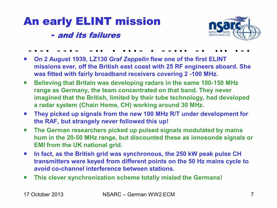
An early ELINT missionAn early ELINT mission
-- and its failuresand its failures
On 2 August 1939, LZ130 Graf Zeppelin flew one of the first ELINT
missions ever, off the British east coast with 25 RF engineers aboard. She
was fitted with fairly broadband receivers covering 2 -100 MHz.
Believing that Britain was developing radars in the same 100-150 MHz
range as Germany, the team concentrated on that band. They never
imagined that the British, limited by their tube technology, had developed
a radar system (Chain Home, CH) working around 30 MHz.
They picked up signals from the new 100 MHz R/T under development for
the RAF, but strangely never followed this up!
The German researchers picked up pulsed signals modulated by mains
hum in the 20-50 MHz range, but discounted these as ionosonde signals or
EMI from the UK national grid.
In fact, as the British grid was synchronous, the 250 kW peak pulse CH
transmitters were keyed from different points on the 50 Hz mains cycle to
avoid co-channel interference between stations.
This clever synchronization scheme totally misled the Germans!

- • - • - - • - - • • • • • • - • - - • • • - • • • • • - •
NSARC – German WW2 ECM 8 17 October 2013
Naval shipboard SIGINT/ELINT Naval shipboard SIGINT/ELINT
centrecentre
Source: Fritz Trenkle
PrinzPrinz EugenEugen ECMECM
centre in foretop.centre in foretop.
Table: Table: R&S R&S SAMOSSAMOS
receiver (80 receiver (80 –– 480 MHz) 480 MHz)
& & W.AnzW.Anz g2 spectrum g2 spectrum
analyzer (146analyzer (146--254MHz).254MHz).
Bulkhead above table:Bulkhead above table:
3 3 NaxosNaxos radar detectors radar detectors
(3 GHz).(3 GHz).
Source:Source: Fritz Fritz TrenkleTrenkle..
Spectrum analyzer displaySpectrum analyzer display

- • - • - - • - - • • • • • • - • - - • • • - • • • • • - •
NSARC – German WW2 ECM 9 17 October 2013
Typical mobile COMINT stationTypical mobile COMINT station
Images courtesy LA6NCAImages courtesy LA6NCA
Left: D/F antenna. Right: HF TX antenna.
Interior: Operator at EP2a RX (75 kHz - 3.3 MHz).
The interceptors passed their data to the ECM (jamming) unit via HF CW, with Enigma encryption. This was often most helpful to Allied ECCM if the traffic was decrypted in time.

- • - • - - • - - • • • • • • - • - - • • • - • • • • • - •
NSARC – German WW2 ECM 10 17 October 2013
Early radar detectors:Early radar detectors:
MetoxMetox, , NaxosNaxos
From 1940, RAF sub-hunter aircraft were fitted with 1.5m Mk. II ASV (Air to Surface Vessel) radar (180-210 MHz).
Mk. II ASV could detect a U-boat at 20 km range. For night ops, a Leigh light (a powerful searchlight steered by the radar) was also fitted. The radar operator switched on the light when radar returns were lost, trapping the U-boat and allowing visual attack.
Metox beeped on detecting radar pulses. The beep rate doubled when the radar operator switched to a higher PRF at closer range, alerting the U-boat to imminent attack. This allowed the boat to crash-dive in time.
Rumours that the Allies were locating U-boats via Metox LO leakage proved untrue – but triggered orders to shut the system down fleet-wide!
The advent of 3 GHz H2S radar in 1943 neutralized Metox, so the German side developed the Naxos series. The US 10 GHz H2X radar deployed by the RAF in 1945, rendered Naxos useless. This is the nature of EW; measure, countermeasure, counter-countermeasure without end.

- • - • - - • - - • • • • • • - • - - • • • - • • • • • - •
NSARC – German WW2 ECM 11 17 October 2013
Examples of radar SIGINT:Examples of radar SIGINT:
FuMBFuMB 1 1 MetoxMetox
Source: Fritz Trenkle
FuMBFuMB 1 1 MetoxMetox: fitted to U: fitted to U--boats to detect British ASV radar (180boats to detect British ASV radar (180--210 MHz)210 MHz)
ReceiverReceiver
RX interiorRX interior
Biscay Cross antenna: erected above
conning-tower hatch & taken below
prior to dive! Bali antenna replaced it.
Newer U-boat mounted Bali
circular dipole (90-470 MHz).

- • - • - - • - - • • • • • • - • - - • • • - • • • • • - •
NSARC – German WW2 ECM 12 17 October 2013
FuGFuG 227 227 Flensburg Flensburg detector:detector:
countermeasure to RAF Monicacountermeasure to RAF Monica
((FuGFuG: : FunkgerFunkgerätät = radio equipment)= radio equipment)
Flensburg cockpit display
Brightness
Focus
Flensburg was a threat receiver fitted to Luftwaffe night-fighters in Spring 1944, and tuned to the 300 MHz emissions of the RAF Monica tail-warning radar. It had good sensitivity and angular discrimination, and enabled the fighter pilot to pick out a single bomber even in a stream, radiating multiple Monica signals.
Flensburg caused such an escalation in bomber losses that RAF Bomber Command ordered withdrawal of Monica from all its aircraft. Similar measures reduced the use of H2S radar sets until the bombers were within 25 km of their targets.

- • - • - - • - - • • • • • • - • - - • • • - • • • • • - •
NSARC – German WW2 ECM 13 17 October 2013
Examples of radar SIGINT:Examples of radar SIGINT:
FuMBFuMB 11 11 –– 17 17 KorfuKorfu ground stationsground stations
((FuMBFuMB: : FunkmeFunkmeßßbeobachtungbeobachtung = radar monitoring) = radar monitoring)
FuMB 11 – 17 Korfu was a superhet system covering the microwave bands 1.6-7.5 GHz, later 7.5-11 and even 11.5-17.7 GHz. It was developed by Blaupunkt Radio GmbH. It gave bearings of aircraft operating H2S/H2X radar.
Kornax-X, with a rotating polyrod antenna, covered the 10 GHz band and was able to detect RAF and USAAF bombers assembling over the English coast, 550 km away. Another variant, Naxburg, used the Würzburg ground radar dish to increase gain.

- • - • - - • - - • • • • • • - • - - • • • - • • • • • - •
Korfu microwave radar
threat receiver
Source: Arthur O. Bauer
NSARC – German WW2 ECM 14 17 October 2013
Plug-in tuning units
cover 3 and 10 GHz bands.
Front end consists of
semiconductor diodes
(NF > 26 dB!) and a split-
anode magnetron LO.

- • - • - - • - - • • • • • • - • - - • • • - • • • • • - •
NSARC – German WW2 ECM 15 17 October 2013
The The NaxosNaxos ZZ Series:Series:
UU--boat, surface ship & airborne variantsboat, surface ship & airborne variants
Sources: Fritz Trenkle, Arthur O. Bauer
Naxos Display & Receiver
Directional display Rotating polyrod antenna
Distant
Near
(Clear plastic radome removed)

- • - • - - • - - • • • • • • - • - - • • • - • • • • • - •
NSARC – German WW2 ECM 16 17 October 2013
The The NaxosNaxos ZZ Series:Series:
Block diagramBlock diagram
Source: Fritz Trenkle
Naxos was a wideband, untuned
detector-type receiver – in effect,
a crystal set. Initially, a ceramic
HPF was fitted as shown, but this
was later removed to improve
sensitivity and reliability.
The polyrod antenna rotated at
1200 rpm to ensure capture of
H2S RF pulses. The detector out-
put was modulated by the radar
PRF and contained a 22 Hz com-
ponent from the rotation.
The CRT was deflected circularly
in sync with the antenna rotation,
A 120 dB gain LF amplifier after
the detector drove the CRT grid
(Z-axis) to create a bright spot on
the display when a signal was
picked up.
Coax
(System diagram)

- • - • - - • - - • • • • • • - • - - • • • - • • • • • - •
NSARC – German WW2 ECM 17 17 October 2013
No limit to the engineers’ No limit to the engineers’
imagination imagination -- a bodya body--worn detector!worn detector!
Indicator, amplifier & batteries
Telefunken FuMB 33 Liliput 1 body-worn detector (2.5-3.75 GHz) for
use in small craft without on-board power. The belt-worn amplifier was
fragile and had poor sensitivity. Due to the 50° beamwidth, the operator
“scanned” by constantly turning his head back and forth. Deployed in
September 1944; 300 units built. Also issued to U-boats.

- • - • - - • - - • • • • • • - • - - • • • - • • • • • - •
NSARC – German WW2 Radar 18 05 March 2009
Notes on microwave Notes on microwave
radar technologyradar technology
It has been reported* that Hitler personally ordered the cessation of all microwave
research in 1941-42. Early in WW2, German scientists tried to get his permission to
work on the development of microwave radar. When told this might take several
years, Hitler refused. His policy required that scientific research produce usable
applications for the military within 6 months' to a year's time. Telefunken even closed
their microwave research laboratories!
Still, German intelligence and scientific personnel were desperate to discover what
the Allies were using. They combed downed Allied bombers for radar equipment,
hoping to piece together a working radar set, or even a recoverable microwave radar
system. Ultimately they succeeded in salvaging enough of an RAF H2S 3 GHz set
(including the cavity magnetron) from the wreckage of a Stirling bomber in Rotterdam
to build a workable system (Rotterdam-Gerät).
The development of the FuG 350 Naxos family of radar detectors was undoubtedly
one of the spinoffs from the H2S capture. (The modern term is “threat warning
receivers”). The ever-increasing numbers of Allied bombers using 3 and 10 GHz
drove German researchers into a frenzied effort to develop microwave radar
countermeasures. *Source: Fritz Trenkle, "Die deutschen Funkmeßverfahren bis 1945"
*

- • - • - - • - - • • • • • • - • - - • • • - • • • • • - •
NSARC – German WW2 Radar 19 05 March 2009
Limitations of German WW2 Limitations of German WW2
microwave receiver technologymicrowave receiver technology
A standing Führerverbot blocked all semiconductor research until 1944.
As a result, the best German solid-state mixer/detector diodes had NF >
26dB. For critical applications, thermionic diodes were used (NF ≈ 16dB).
Frequency generation above 1 GHz was also a major problem due to
vacuum-tube limitations. The split-anode magnetron was used as LO at 3
and 10 GHz, but was unstable and limited in power output.
The Allies used reflex klystrons as radar LO‘s, but Germany acquired this
technology only after WW2.
An irrational fear of LO leakage and consequent detection by Allied SIGINT
inhibited deployment of VHF/UHF and microwave superhet detectors. This
was later proven to be largely unfounded.
Microwave test equipment was all but non-existent right up to war’s end.
The best lab signal generator used a buzzer as a signal source!
Constant Allied bombing of electronics R&D and manufacturing sites, plus
ongoing sabotage at sites in occupied Europe, created extreme shortages
of specialized components such as tubes, RF tuning assemblies etc. Inter-
organizational secrecy also created enormous difficulties.

- • - • - - • - - • • • • • • - • - - • • • - • • • • • - •
NSARC – German WW2 ECM 20 17 October 2013
Jamming objectives:Jamming objectives:
commcomm//navnav, radar & broadcasting, radar & broadcasting
CommunicationsCommunications Tactical ground radio (HF, VHF)Tactical ground radio (HF, VHF)
Airborne R/T (VHF)Airborne R/T (VHF)
Naval CW and R/T (LF, HF)Naval CW and R/T (LF, HF)
Navigational aidsNavigational aids GEE (British VHF hyperbolic navigation)GEE (British VHF hyperbolic navigation)
OBOE I & II (VHF & UHF blindOBOE I & II (VHF & UHF blind--bombing aids)bombing aids)
RadarsRadars VHF ground radar (CH, CD, CHL)VHF ground radar (CH, CD, CHL)
VHF airborne (AI, ASV)VHF airborne (AI, ASV)
Microwave airborne (HMicrowave airborne (H22S, HS, H22X)X)
Naval shore radars (VHF & microwave)Naval shore radars (VHF & microwave)
BroadcastingBroadcasting BBC services to Germany & occupied EuropeBBC services to Germany & occupied Europe
Responsibility of Post Office, not armed forcesResponsibility of Post Office, not armed forces

- • - • - - • - - • • • • • • - • - - • • • - • • • • • - •
NSARC – German WW2 ECM 21 17 October 2013
Communications jammersCommunications jammers
HF: In general, the German monitoring sites preferred to glean COMINT HF: In general, the German monitoring sites preferred to glean COMINT from strategic HF from strategic HF commscomms links than to jam them.links than to jam them. Example: German Example: German ““cracking” of Londoncracking” of London--New York R/T link used by FDR and Churchill.New York R/T link used by FDR and Churchill.
By contrast, tactical situations e.g. transmission of critical orders, reports By contrast, tactical situations e.g. transmission of critical orders, reports on German force dispositions, emergency calls from convoys under Uon German force dispositions, emergency calls from convoys under U--boat attack etc. called for boat attack etc. called for ad hoc ad hoc jamming. jamming. FuG10FuG10 HF transmitters (S 10 K, 70W) were modified to jam Soviet HF airborne R/T, but were HF transmitters (S 10 K, 70W) were modified to jam Soviet HF airborne R/T, but were
never deployed. Ancient spark transmitters were even “dusted off” in a few cases!never deployed. Ancient spark transmitters were even “dusted off” in a few cases!
Land and shipboard HF transmitters (typ. 200W Land and shipboard HF transmitters (typ. 200W –– 1.5 kW) were tuned to 1.5 kW) were tuned to the target frequency and either keyed rapidly and irregularly or noisethe target frequency and either keyed rapidly and irregularly or noise--modulated. A modulated. A spectrum analyzer spectrum analyzer served as a tuning aid in some systems.served as a tuning aid in some systems. Examples: holding the Examples: holding the micmic to the HV dynamotor PSU, to the HV dynamotor PSU, micmic in aircraft engine housing.in aircraft engine housing.
Allied VHF air/ground RAllied VHF air/ground R/T in 100/T in 100--156 MHz band was attacked by 156 MHz band was attacked by Caruso Caruso (30W), later by (30W), later by Karl I Karl I (400W) & (400W) & Karl IIKarl II (2 kW) jammers (90(2 kW) jammers (90--150 MHz), 150 MHz), StarnbergStarnberg II II (98(98--156 MHz, 20W) and FuG40 156 MHz, 20W) and FuG40 Nervtöter Nervtöter (Gadfly, 25W) (Gadfly, 25W) covering 90covering 90--140 MHz140 MHz. Lower. Lower--powered units were probably airborne. US powered units were probably airborne. US deployment of UHF (225deployment of UHF (225--400 MHz) R/T largely eliminated this problem.400 MHz) R/T largely eliminated this problem. Modulation: Caruso: 150 Hz triangular wave. Karl: Modulation: Caruso: 150 Hz triangular wave. Karl: sawtoothsawtooth. .

- • - • - - • - - • • • • • • - • - - • • • - • • • • • - •
Telefunken AS60 HF transmitter
- suitable for jamming service
Source: Arthur O. Bauer
NSARC – German WW2 ECM 22 17 October 2013
The AS60 may have been
designed by the same group
as the E52 Köln receiver.
Bandswitched VFO drive unit
with optical projection freq.
display allowed precise tuning
onto target signal. Freq. stabi-
lity 5 * 10-6 per °C.
The AS60 was intended as a
fixed or shipboard HF comms
transmitter, but its high power
and stability made it very sui-
table for jamming missions.

- • - • - - • - - • • • • • • - • - - • • • - • • • • • - •
NSARC – German WW2 ECM 23 17 October 2013
Jamming of navigational aidsJamming of navigational aids
GEEGEE
GEEGEE was a hyperbolic navigation system in which a receiver aboard an was a hyperbolic navigation system in which a receiver aboard an aircraft or vessel measured the time delay between two pulsed radio aircraft or vessel measured the time delay between two pulsed radio signals to yield a “fix”. Operational until 1970.signals to yield a “fix”. Operational until 1970.
The system operated in the 20The system operated in the 20--30, 4030, 40--50, 5050, 50--70 and 7070 and 70--90 MHz bands. The 90 MHz bands. The onon--board receiver had plugboard receiver had plug--in RF units for rapid QSY in the event of in RF units for rapid QSY in the event of jamming. jamming.
The Germans captured receivers from downed bombers, and devised The Germans captured receivers from downed bombers, and devised effective jamming systems in which “spoof” ground stations in France or effective jamming systems in which “spoof” ground stations in France or Holland transmitted fake pulses.Holland transmitted fake pulses.
Using D/F receivers and loops, Allied radio operators could often identify Using D/F receivers and loops, Allied radio operators could often identify false signals.false signals.
The The Breslau I Breslau I (22(22--28 MHz) and28 MHz) and Breslau II Breslau II (40(40--50 MHz) jammers were very 50 MHz) jammers were very effective against GEE. Each had 5 1 kW effective against GEE. Each had 5 1 kW PA’sPA’s (2 LS180 triodes in push(2 LS180 triodes in push--pull) pull) and a complex pulse modulator synced to the British GEE pulses.and a complex pulse modulator synced to the British GEE pulses.
AM at 20 kHz could also be applied to the RF pulses for further confusion.AM at 20 kHz could also be applied to the RF pulses for further confusion.

- • - • - - • - - • • • • • • - • - - • • • - • • • • • - •
Breslau II jamming transmitter
- against GEE & British low-band radars
Source: Fritz Trenkle
NSARC – German WW2 ECM 24 17 October 2013
1 kW transmitter chassis
(2 X LS180 in push-pull)
TX 1 TX 2
TX 3 TX 4
TX5
Exciter Mod
CU
PSU

- • - • - - • - - • • • • • • - • - - • • • - • • • • • - •
NSARC – German WW2 ECM 25 17 October 2013
Jamming of navigational aidsJamming of navigational aids
OBOE I & II OBOE I & II (German codename (German codename BumerangBumerang))
OBOEOBOE was a transponderwas a transponder--based aerial blindbased aerial blind--bombing system using two bombing system using two fixed stations in England. These stations transmitted a signal to a fixed stations in England. These stations transmitted a signal to a Pathfinder bomber fitted with a transponder which repeated the signals to Pathfinder bomber fitted with a transponder which repeated the signals to the ground stations. the ground stations.
The signal transit times enabled the ground stations to guide the bomber The signal transit times enabled the ground stations to guide the bomber on a circular path to the target. A computer at one of the stations on a circular path to the target. A computer at one of the stations determined the bombsdetermined the bombs--away point, and transmitted the bombaway point, and transmitted the bomb--release release signal to the bomber.signal to the bomber.
OBOE 1 operated on 200OBOE 1 operated on 200--250 MHz with PRF ≈ 133 Hz. It was vulnerable to 250 MHz with PRF ≈ 133 Hz. It was vulnerable to jamming and “spoofing” by ABG jamming and “spoofing” by ABG (Anti(Anti--BumerangBumerang--GerGerätät)), an interrogator, an interrogator--repeater system.repeater system.
ABG repeated the airborne transponder’s downlink signal back to the ABG repeated the airborne transponder’s downlink signal back to the bomber on its uplink frequency at 25 kW peak pulse power and 200 Hz bomber on its uplink frequency at 25 kW peak pulse power and 200 Hz PRF, thus capturing the transponder in a feedback loop. PRF, thus capturing the transponder in a feedback loop.
OBOE II, operating at 3 GHz, evaded this jamming. Several Marks OBOE II, operating at 3 GHz, evaded this jamming. Several Marks otot 3 GHz 3 GHz ABG were built, but never seriously compromised OBOE.ABG were built, but never seriously compromised OBOE.

- • - • - - • - - • • • • • • - • - - • • • - • • • • • - •
ABG (Anti(Anti--BumerangBumerang--GerGerät) ät) AA
- against OBOE I
Source: Fritz Trenkle
NSARC – German WW2 ECM 26 17 October 2013
ABG A antenna mast

- • - • - - • - - • • • • • • - • - - • • • - • • • • • - •
NSARC – German WW2 ECM 27 17 October 2013
Jamming of British radarsJamming of British radars
VHF/UHF: CH, CHL, CD, AI, ASVVHF/UHF: CH, CHL, CD, AI, ASV
Microwave: HMicrowave: H22S, HS, H
22X, newer AI & ASVX, newer AI & ASV
Chain Home (CH) operated in the 20Chain Home (CH) operated in the 20--55 MHz band; Chain Home Low (CHL)55 MHz band; Chain Home Low (CHL)
and CD (Coastal Defence) radar used the180-210 MHz band, as did band, as did
Airborne Interception (AI to Mk V) and Air to Surface Vessel (ASV) radars.Airborne Interception (AI to Mk V) and Air to Surface Vessel (ASV) radars.
Prior to the cavity magnetron (early 1941), 200 MHz was the most widelyPrior to the cavity magnetron (early 1941), 200 MHz was the most widely--
used band in Allied radar. used band in Allied radar. DDüppel, üppel, the German version of the German version of WindowWindow (chaff) (chaff)
used 75cm foil strips (used 75cm foil strips (λλ/2 at 200 MHz). A variety of German jammers e.g. /2 at 200 MHz). A variety of German jammers e.g.
Breslau II, Karl IIBreslau II, Karl II etc. covered 200 etc. covered 200 MHz.MHz.
Microwave radar jamming was more problematical; the power levels Microwave radar jamming was more problematical; the power levels
required to jam effectively were beyond German capabilities. Transmitters required to jam effectively were beyond German capabilities. Transmitters
using using LMS 10 LMS 10 cavity magnetrons were unreliable and ineffective. cavity magnetrons were unreliable and ineffective.
PostklystronPostklystron, a 100W transmitter using a water, a 100W transmitter using a water--cooled klystron with horn cooled klystron with horn
or dish antennas, was deployed in 1943or dish antennas, was deployed in 1943--44 against 3 GHz radars (H44 against 3 GHz radars (H22S, S,
newer AI & ASV) but had no strategic impact.newer AI & ASV) but had no strategic impact.
By war’s end, there was still no effective German 10 GHz jammer.By war’s end, there was still no effective German 10 GHz jammer.

- • - • - - • - - • • • • • • - • - - • • • - • • • • • - •
NSARC – German WW2 ECM 28 17 October 2013
General principles of radar General principles of radar
jammingjamming
“Brute“Brute--force” method, where an force” method, where an unmodulatedunmodulated or “or “wobbulatedwobbulated” carrier ” carrier
swamps echoes at radar receiver, is effective but requires very high ERP.swamps echoes at radar receiver, is effective but requires very high ERP.
Carrier modulated by triangular pulses with PRF slightly higher than that Carrier modulated by triangular pulses with PRF slightly higher than that
of target radar generates false echoes.of target radar generates false echoes.
Pulsed microwave jamming transmitter with pulsePulsed microwave jamming transmitter with pulse--shaping to enhance shaping to enhance
false echoes at target radar receiver, at PRF close to that of target radar, false echoes at target radar receiver, at PRF close to that of target radar,
can “trash” PPI (plancan “trash” PPI (plan--position indicator) displays.position indicator) displays.
The pulsed microwave jammer can be even more effective if AFC derived The pulsed microwave jammer can be even more effective if AFC derived
from a receiver capturing the target radar’s emissions holds the jammer from a receiver capturing the target radar’s emissions holds the jammer
exactly on the target’s frequency. exactly on the target’s frequency.
Despite some early successes, German radar jamming was strategically Despite some early successes, German radar jamming was strategically
ineffective in the end as Allied technology was advancing too rapidly.ineffective in the end as Allied technology was advancing too rapidly.

- • - • - - • - - • • • • • • - • - - • • • - • • • • • - •
Karl I jamming transmitter(2 kW)
- against 200 MHz radars
Source: Fritz Trenkle
NSARC – German WW2 ECM 29 17 October 2013
Tube sockets
LS1500 triode
(1 kW dissipation)
PA stage w/tuned anode lines
Arrows: cooling air for grid circuit & output coupling loop
Modulation: Triangular
waves at 150 kHz

- • - • - - • - - • • • • • • - • - - • • • - • • • • • - •
Examples of jammed radar
displays
Source: Fritz Trenkle
NSARC – German WW2 ECM 30 17 October 2013
A-scope jammed by 30 kHz pulses, almost masking echo
A-scope jammed by high-power noise-modulated signal
PPI jammed by pulsed magnetron TX

- • - • - - • - - • • • • • • - • - - • • • - • • • • • - •
NSARC – German WW2 ECM 31 17 October 2013
Operation Channel Dash Operation Channel Dash (Cerberus)(Cerberus)
-- a case history of radar jamminga case history of radar jamming
Operation Operation Channel Dash Channel Dash (German: (German: UnternehmenUnternehmen CerberusCerberus) was the planned escape ) was the planned escape
of the battleships of the battleships Scharnhorst, Scharnhorst, GneisenauGneisenau andand PrinzPrinz EugenEugen from the French port of from the French port of
Brest, up the English Channel to the North Sea and thence to Germany.Brest, up the English Channel to the North Sea and thence to Germany.
A key component of the plan was the jamming of British CH and CD (CHL) coastal A key component of the plan was the jamming of British CH and CD (CHL) coastal
radars by multiple jamming sites along the Normandy coast. German accounts hold radars by multiple jamming sites along the Normandy coast. German accounts hold
this up as key to the plan’s success, but the Germans were unaware of cothis up as key to the plan’s success, but the Germans were unaware of co--sited 3 GHz sited 3 GHz
CD Mk. IV (NT 271) radars which were thus not jammed. These radars detected and CD Mk. IV (NT 271) radars which were thus not jammed. These radars detected and
duly reported the escaping fleet.duly reported the escaping fleet.
Ultimately, Channel Dash succeeded because of a number of snafu’s on the British Ultimately, Channel Dash succeeded because of a number of snafu’s on the British
side; interside; inter--service information barriers, RAF Coastal Command patrols with nonservice information barriers, RAF Coastal Command patrols with non--
working ASV Mk. II (200 MHz) radar and radio silence rules blocking timely reporting working ASV Mk. II (200 MHz) radar and radio silence rules blocking timely reporting
of sightings. Inexplicably, the ASV’s were not jammed.of sightings. Inexplicably, the ASV’s were not jammed.
Despite their escape, all 3 battleships were effectively neutralized. Scharnhorst & Despite their escape, all 3 battleships were effectively neutralized. Scharnhorst &
GneisenauGneisenau were damaged beyond use, and were damaged beyond use, and PrinzPrinz EugenEugen was “stuck” in a Norwegian was “stuck” in a Norwegian
port until the end of WW2.port until the end of WW2.

- • - • - - • - - • • • • • • - • - - • • • - • • • • • - •
NSARC – German WW2 ECM 32 17 October 2013
Acknowledgements & references
1. Foundation for German Communications
2. Fritz Trenkle (many images)
3. Fritz Trenkle, „Die deutschen Funkstörverfahren
bis 1945“, AEG-Telefunken
4. Alfred Price, “Instruments of Darkness”,
Greenhill Books
5. Louis Brown, “A Radar History of World War II”,
IoP Publishing
6. Werner Niehaus, „Die Radarschlacht“,
Motorbuch-Verlag

- • - • - - • - - • • • • • • - • - - • • • - • • • • • - •
NSARC – German WW2 ECM 33 17 October 2013
Links for further studyLinks for further study
http://www.radarworld.org/germany.html
Foundation for German Communications
Aspects of German Airborne Radar, 1942-45
http://www.cdvandtext2.org/ADIK380all.pdf
The Effects of Interception Procedures Interesting video on German ECM/EW, in German, notes in Dutch

- • - • - - • - - • • • • • • - • - - • • • - • • • • • - •
NSARC – German WW2 ECM 34 17 October 2013
Future Presentations on Future Presentations on
German WW2 RF TopicsGerman WW2 RF Topics
Radio Direction Finding: Allied & German
land, airborne & naval D/F, including British
“Huff-Duff”