Geotextile Sand Filter - Eljen Manuals- PDF/PA Manual 7-15.pdf · 2015 Pennsylvania Design &...
32
Geotextile Sand Filter CORPORATION Innovative Environmental Products & Solutions Since 1970
Transcript of Geotextile Sand Filter - Eljen Manuals- PDF/PA Manual 7-15.pdf · 2015 Pennsylvania Design &...
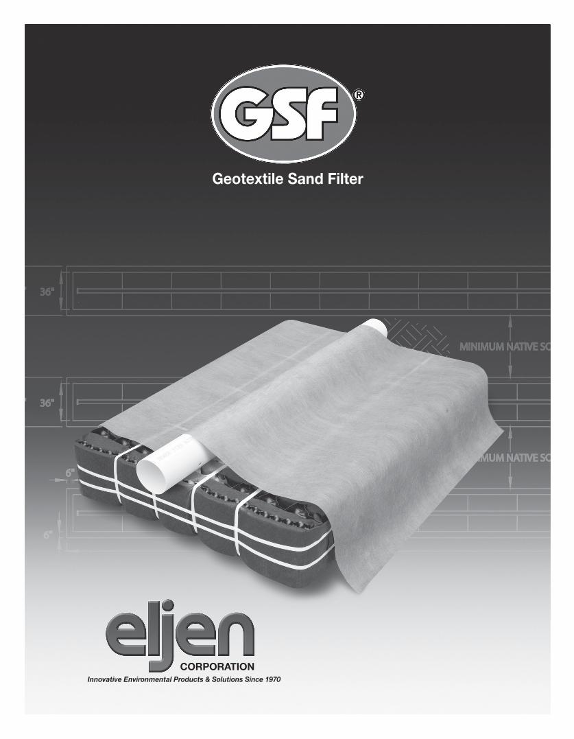
Geotextile Sand Filter
CORPORATIONInnovative Environmental Products & Solutions Since 1970
Tech1
Typewritten Text
Tech1
Typewritten Text
Pennsylvania Design & Installation Manual
Tech1
Typewritten Text
Tech1
Typewritten Text
Tech1
Typewritten Text
www.eljen.com
Tech1
Typewritten Text
July 2015
2015 Pennsylvania Design & Installation Manual 2 www.eljen.com
Table of Contents
SUBJECT
GLOSSARY OF TERMS ...................................................................................................................................... 3 GSF SYSTEM DESCRIPTION ............................................................................................................................ 4 TESTING AND PERFORMANCE ........................................................................................................................ 5 1.0 DESIGN AND INSTALLATION ...................................................................................................................... 6 GSF SIZING EXAMPLE – PRESSURE DOSED MOUND DESIGN: <61 MIN/INCH ........................................ 11 GSF SIZING EXAMPLE – PRESSURE DOSED MOUND DESIGN: 61+ MIN/INCH ........................................ 14 GSF SIZING EXAMPLE – LESS THAN 20 INCHES FROM LIMITING HORIZON ........................................... 17 2.0 ELEVATED GSF INSTALLATION GUIDELINE ........................................................................................... 19 3.0 IN-GROUND TRENCH INSTALLATION GUIDELINE ................................................................................. 20 4.0 IN-GROUND BED INSTALLATION GUIDELINE ......................................................................................... 21 MOUND DRAWINGS ......................................................................................................................................... 22 5.0 PRESSURE DISTRIBUTION GUIDANCE ................................................................................................... 23 6.0 DOSING DISTRIBUTION GUIDANCE ........................................................................................................ 27 7.0 PUMP CONTROLS ...................................................................................................................................... 27 8.0 SYSTEM VENTILATION .............................................................................................................................. 28 SYSTEM VENTILATION EXAMPLE DRAWINGS ............................................................................................. 28 ELJEN INSTALLATION CHECK LIST ............................................................................................................... 31
GSF FIGURES
FIGURE 1: GSF SYSTEM OPERATION ........................................................................................................... 4 FIGURE 2: CROSS SECTION FOR PERCOLATION RATES FROM 3 MIN/IN – 60 MIN/IN ............................ 6 FIGURE 3: CROSS SECTION FOR PERCOLATION RATES FROM 61 MIN/IN – 180 MIN/IN ........................ 6 FIGURE 4: MINIMUM VERTICAL ISOLATION DISTANCES FOR FINAL TREATMENT ................................. 8 FIGURE 5: B43 PRESSURE DOSED CENTRAL MANIFOLD MOUND DESIGN – 3 BED – 31 MIN/INCH ... 12 FIGURE 6: B43 PRESSURE DOSED END FEED MOUND DESIGN – 3 BED – 31 MIN/INCH ...................... 12 FIGURE 7: B43 PRESSURE DOSED MOUND DESIGN – CROSS SECTION – 3 BED – 31 MIN/INCH ........ 13 FIGURE 8: B43 PRESSURE DOSED CENTRAL MANIFOLD MOUND DESIGN – 3 BED – 61 MIN/INCH ... 15 FIGURE 9: B43 PRESSURE DOSED END FEED MOUND DESIGN – 3 BEDROOMS – 61 MIN/INCH ......... 15 FIGURE 10: B43 PRESSURE DOSED MOUND DESIGN – CROSS SECTION 3 BED – 61 MIN/INCH ........... 16 FIGURE 11: LESS THAN 20 INCHES FROM LIMITING HORIZON PLAN VIEW – CENTER FED................... 18 FIGURE 12: LESS THAN 20 INCHES FROM LIMITING HORIZON PLAN VIEW – END FED .......................... 18 FIGURE 13: LESS THAN 20 INCHES FROM LIMITING HORIZON CROSS SECTION ................................... 18 FIGURE 14: B43 SINGLE LATERAL MOUND SYSTEM................................................................................... 22 FIGURE 15: B43 MULTIPLE LATERAL MOUND SYSTEM .............................................................................. 22 FIGURE 16: B43 MULTIPLE LATERAL MOUND SYSTEM .............................................................................. 22 FIGURE 17: PRESSURE PIPE PLACEMENT .................................................................................................. 24 FIGURE 18: ALTERNATIVE HOLE PLACEMENT FOR 4 INCH DISTRIBUTION PIPE ................................... 25 FIGURE 19: ALTERNATIVE HOLE PLACEMENT FOR 4 INCH DISTRIBUTION PIPE ................................... 25 FIGURE 20: CONTOURED TRENCH PRESSURE DISTRIBUTION ................................................................ 26 FIGURE 21: EXAMPLE PRESSURE DISTRIBUTION ...................................................................................... 26 FIGURE 22: PRESSURE CLEAN OUT AND VENT FOR A PRESSURE DOSED SYSTEM ............................ 27 FIGURE 23: VENT FOR GRAVITY AND PRESSURE DOSED SYSTEMS ...................................................... 28 FIGURE 24: GSF WITH 4” VENT EXTENDED TO CONVENIENT LOCATION ................................................ 29
GSF TABLES
TABLE 1: SPECIFIED SAND SIEVE REQUIREMENTS ................................................................................... 3 TABLE 2: TESTING RESULTS .......................................................................................................................... 5 TABLE 3: EXAMPLE GUIDE ............................................................................................................................ 10 TABLE 4: DESIGN SUMMARY TABLE............................................................................................................ 10 TABLE 5: HYDRAULIC LINEAR LOADING RATE TABLE .............................................................................. 30
2015 Pennsylvania Design & Installation Manual 3 www.eljen.com
Glossary of Terms
B43 Module (or Module) Dimensions – 48” x 36” x 7” (L x W x H)
Cover Fabric The geotextile cover fabric (provided by manufacturer) that is placed over the GSF modules.
Design Flow The estimated peak daily flow that is used to size a GSF system, and is in accordance with Chapter 73.
Distribution Box A plastic or concrete box that receives effluent from a septic tank and splits the flow to pipes placed above the GSF modules. For equal distribution, the outlet pipe orifices are typically set at the same elevation to equalize the flow to each line.
GSF The Eljen Geotextile Sand Filter modules and the sand layer along the base and sides of the modules.
GSF Module The individual module of a GSF system. The module is comprised of a cuspated plastic core and corrugated geotextile fabric.
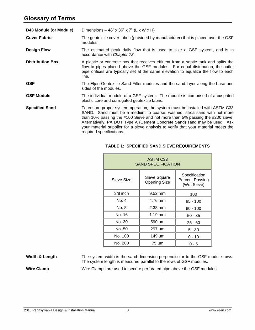
Specified Sand To ensure proper system operation, the system must be installed with ASTM C33 SAND. Sand must be a medium to coarse, washed, silica sand with not more than 10% passing the #100 Sieve and not more than 5% passing the #200 sieve. Alternatively, PA DOT Type A (Cement Concrete Sand) sand may be used. Ask your material supplier for a sieve analysis to verify that your material meets the required specifications.
TABLE 1: SPECIFIED SAND SIEVE REQUIREMENTS
ASTM C33 SAND SPECIFICATION
Sieve Size Sieve Square Opening Size
Specification Percent Passing
(Wet Sieve)
3/8 inch 9.52 mm 100
No. 4 4.76 mm 95 - 100
No. 8 2.38 mm 80 - 100
No. 16 1.19 mm 50 - 85
No. 30 590 µm 25 - 60
No. 50 297 µm 5 - 30
No. 100 149 µm 0 - 10
No. 200 75 µm 0 - 5
Width & Length The system width is the sand dimension perpendicular to the GSF module rows. The system length is measured parallel to the rows of GSF modules.
Wire Clamp Wire Clamps are used to secure perforated pipe above the GSF modules.
2015 Pennsylvania Design & Installation Manual 4 www.eljen.com
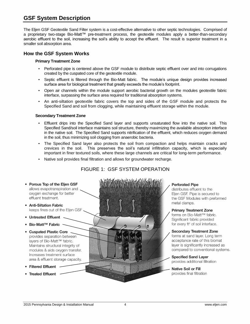
GSF System Description
The Eljen GSF Geotextile Sand Filter system is a cost-effective alternative to other septic technologies. Comprised of a proprietary two-stage Bio-Matt™ pre-treatment process, the geotextile modules apply a better-than-secondary aerobic effluent to the soil, increasing the soil’s ability to accept the effluent. The result is superior treatment in a smaller soil absorption area.
How the GSF System Works
Primary Treatment Zone
▪ Perforated pipe is centered above the GSF module to distribute septic effluent over and into corrugations created by the cuspated core of the geotextile module.
▪ Septic effluent is filtered through the Bio-Matt fabric. The module’s unique design provides increased surface area for biological treatment that greatly exceeds the module’s footprint.
▪ Open air channels within the module support aerobic bacterial growth on the modules geotextile fabric interface, surpassing the surface area required for traditional absorption systems.
▪ An anti-siltation geotextile fabric covers the top and sides of the GSF module and protects the Specified Sand and soil from clogging, while maintaining effluent storage within the module.
Secondary Treatment Zone
▪ Effluent drips into the Specified Sand layer and supports unsaturated flow into the native soil. This Specified Sand/soil interface maintains soil structure, thereby maximizing the available absorption interface in the native soil. The Specified Sand supports nitrification of the effluent, which reduces oxygen demand in the soil, thus minimizing soil clogging from anaerobic bacteria.
▪ The Specified Sand layer also protects the soil from compaction and helps maintain cracks and crevices in the soil. This preserves the soil’s natural infiltration capacity, which is especially important in finer textured soils, where these large channels are critical for long-term performance.
▪ Native soil provides final filtration and allows for groundwater recharge.
FIGURE 1: GSF SYSTEM OPERATION
2015 Pennsylvania Design & Installation Manual 5 www.eljen.com
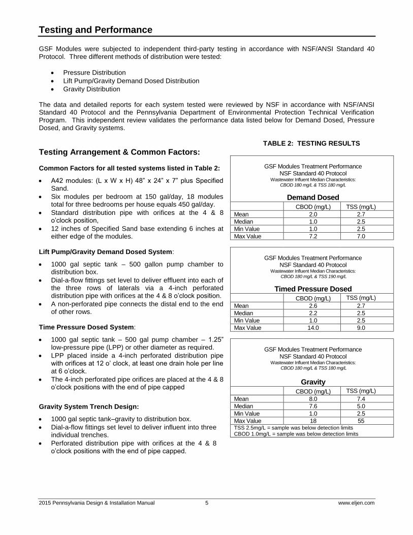
Testing and Performance
GSF Modules were subjected to independent third-party testing in accordance with NSF/ANSI Standard 40 Protocol. Three different methods of distribution were tested:
Pressure Distribution
Lift Pump/Gravity Demand Dosed Distribution
Gravity Distribution The data and detailed reports for each system tested were reviewed by NSF in accordance with NSF/ANSI Standard 40 Protocol and the Pennsylvania Department of Environmental Protection Technical Verification Program. This independent review validates the performance data listed below for Demand Dosed, Pressure Dosed, and Gravity systems.
TABLE 2: TESTING RESULTS
Testing Arrangement & Common Factors: Common Factors for all tested systems listed in Table 2:
A42 modules: (L x W x H) 48” x 24” x 7” plus Specified Sand.
Six modules per bedroom at 150 gal/day, 18 modules total for three bedrooms per house equals 450 gal/day.
Standard distribution pipe with orifices at the 4 & 8 o’clock position,
12 inches of Specified Sand base extending 6 inches at either edge of the modules.
Lift Pump/Gravity Demand Dosed System:
1000 gal septic tank – 500 gallon pump chamber to distribution box.
Dial-a-flow fittings set level to deliver effluent into each of the three rows of laterals via a 4-inch perforated distribution pipe with orifices at the 4 & 8 o’clock position.
A non-perforated pipe connects the distal end to the end of other rows.
Time Pressure Dosed System:
1000 gal septic tank – 500 gal pump chamber – 1.25” low-pressure pipe (LPP) or other diameter as required.
LPP placed inside a 4-inch perforated distribution pipe with orifices at 12 o’ clock, at least one drain hole per line at 6 o’clock.
The 4-inch perforated pipe orifices are placed at the 4 & 8 o’clock positions with the end of pipe capped
Gravity System Trench Design:
1000 gal septic tank–gravity to distribution box.
Dial-a-flow fittings set level to deliver influent into three individual trenches.
Perforated distribution pipe with orifices at the 4 & 8 o’clock positions with the end of pipe capped.
GSF Modules Treatment Performance
NSF Standard 40 Protocol Wastewater Influent Median Characteristics:
CBOD 180 mg/L & TSS 180 mg/L
Demand Dosed
CBOD (mg/L) TSS (mg/L)
Mean 2.0 2.7
Median 1.0 2.5
Min Value 1.0 2.5
Max Value 7.2 7.0
GSF Modules Treatment Performance
NSF Standard 40 Protocol Wastewater Influent Median Characteristics:
CBOD 180 mg/L & TSS 190 mg/L
Timed Pressure Dosed
CBOD (mg/L) TSS (mg/L)
Mean 2.6 2.7
Median 2.2 2.5
Min Value 1.0 2.5
Max Value 14.0 9.0
GSF Modules Treatment Performance
NSF Standard 40 Protocol Wastewater Influent Median Characteristics:
CBOD 180 mg/L & TSS 180 mg/L
Gravity CBOD (mg/L) TSS (mg/L)
Mean 8.0 7.4
Median 7.6 5.0
Min Value 1.0 2.5
Max Value 18 55 TSS 2.5mg/L = sample was below detection limits CBOD 1.0mg/L = sample was below detection limits
2015 Pennsylvania Design & Installation Manual 6 www.eljen.com
1.0 Design and Installation
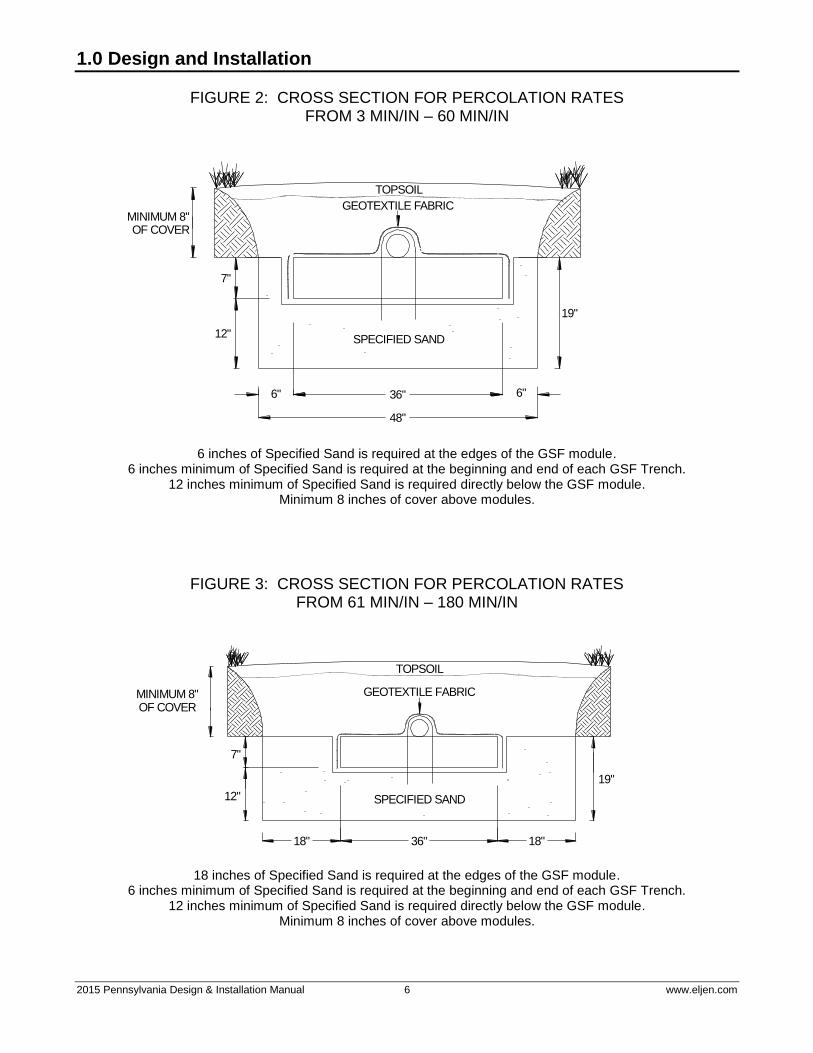
FIGURE 2: CROSS SECTION FOR PERCOLATION RATES FROM 3 MIN/IN – 60 MIN/IN
48"
36"6" 6"
SPECIFIED SAND
GEOTEXTILE FABRICMINIMUM 8"OF COVER
7"
12"
19"
TOPSOIL
6 inches of Specified Sand is required at the edges of the GSF module. 6 inches minimum of Specified Sand is required at the beginning and end of each GSF Trench.
12 inches minimum of Specified Sand is required directly below the GSF module. Minimum 8 inches of cover above modules.
FIGURE 3: CROSS SECTION FOR PERCOLATION RATES FROM 61 MIN/IN – 180 MIN/IN
TOPSOIL
GEOTEXTILE FABRICMINIMUM 8"OF COVER
SPECIFIED SAND
19"
18"36"18"
12"
7"
18 inches of Specified Sand is required at the edges of the GSF module. 6 inches minimum of Specified Sand is required at the beginning and end of each GSF Trench.
12 inches minimum of Specified Sand is required directly below the GSF module. Minimum 8 inches of cover above modules.

2015 Pennsylvania Design & Installation Manual 7 www.eljen.com
1.0 Design and Installation
1.1 REQUIREMENTS: GSF Design and Installation must meet Pennsylvania Title 25, Chapter 73 (hereinafter the Guidelines), except as outlined in this manual.
The sizing information in Section 1.17 of this manual applies to systems that serve residential development or other facilities producing sewage having chemical characteristics typical of untreated domestic wastewater (reference the Eljen GSF onlot listing #A2010-0007-0005). Please contact Eljen’s Technical Resource Department at 1-800-444-1359 for design information on systems not covered in this manual.
1.2 SPECIFIED SAND SPECIFICATION FOR GSF SYSTEMS: Specified Sand immediately under, between rows, and around the perimeter of the GSF system must be an ASTM C33 WASHED CONCRETE SAND WITH LESS THAN 10% PASSING A #100 SIEVE AND LESS THAN 5% PASSING A #200 SIEVE. Alternatively, PA DOT Type A (Cement Concrete Sand) sand may be used. Ask your material supplier for a sieve analysis to verify that your material meets the required specifications. Please place a prominent note to this effect on each design drawing. See Table 1 for more information on the ASTM C33 sand and sieve specifications.
The minimum amount of sand required at the beginning and end of each module row is six inches (6”) of sand. A minimum of twelve (12”) of specified sand must be place underneath modules. For percolation rates ranging between 3 min/in to 60 min/in, a minimum of six inches (6”) of sand must be placed at the perimeter of the modules. For percolation rates ranging from 61 min/in to 180 min/in, a minimum of eighteen inches (18”) of sand will be required along the sides of the modules. A minimum of twelve inches (12”) of specified sand must be used between rows or modules in beds with percolations rates between 3 min/in to 60 min/in. For percolation rates between 61 min/in to 180 min/in, thirty-six inches (36”) of specified sand between rows of modules in beds must be used.
1.3 CONNECTIONS AND FITTINGS: Connections of lines to tanks and distribution boxes must be made in accordance with local codes and regulations.
1.4 PLACING GSF MODULES: The “White Stripe” on the GSF modules indicates the top of the module and is not intended to indicate the location of the distribution pipe. With the white stripe facing up, all rows of GSF modules are set level, end to end on the Specified Sand layer. No mechanical connection is required between modules.
1.5 DISTRIBUTION PIPE:
For gravity systems, the PVC pipe distributing effluent to the B43 modules shall meet the following specifications: The diameter of the SDR-35 or equivalent pipe shall be 4 inches. The perforations shall be located at both the 4 o’clock and 8 o’clock positions.
For pressurized systems, the PVC pipe distributing effluent to the B43 modules shall meet the following specifications: The diameter of the SDR-35 or equivalent pipe shall be 4 inches. The perforations shall be located at both the 4 o’clock and 8 o’clock positions.
For Pressurized systems only - The 4 inch distribution pipe may also have perforations that conform to the following configuration:
Pipe purchased from a manufacturer shall have a 3-hole perforation with the 5/8” diameter holes located at the 4 o’clock, 6 o’clock, and 8 o’clock positions.
Pipe purchased from a manufacturer shall have a 2-hole perforation with the 5/8” diameter holes located at the 4 o’clock and 8 o’clock positions. Additional perforations at the 6 o’clock position are acceptable provided that there are three 6 o’clock perforations in the pipe for each B43 module. The perforations shall be placed such that the first hole be placed 8” from the end of the B43 module. Subsequent perforations shall be placed 16” center to center (i.e. one 6 o’clock perforation 8” from the end of each module and one 6 o’clock perforation in the center of the B43 module.). The diameter of the perforations at the 6 o’clock shall be either 5/8” diameter or 3/4" diameter.

2015 Pennsylvania Design & Installation Manual 8 www.eljen.com
1.0 Design and Installation
For pressurized systems, the lateral (inner pipe) design must generally conform to Section 73.44 with the following clarification. The discharge holes should be “nominally” 6’ on center, but no farther apart than 10’ and shall be evenly spaced along the lateral length. The distance from the last hole in the lateral to the end of the lateral shall be equal to the distance from the edge of the first module to the first hole. The orifices for the discharge holes must be placed at the 12 o’clock position and shall include a minimum of one 1/4” diameter drain hole at the 6 o’clock position for each lateral.
Distribution of effluent to the individual laterals shall be by:
A central manifold extending into the absorption area from the delivery pipe, or
A header located at the beginning or the end of the system,
The overall length of the laterals may exceed 51 feet
1.6 DISTRIBUTION BOX: Set the gravity system D-box outlet invert a minimum of ⅛ inch drop in elevation per linear foot to the top first module in the row. Set a 2-inch minimum drop for dosed systems from the D-box to the modules. Ensure that the distribution box and pipes feeding the system are placed on settled soil. Flow Dials may be used in either Gravity or Dosed installations.
1.7 COVER FABRIC: Geotextile cover fabric is provided by Eljen Corporation for all GSF systems. It is placed over the top and sides of the module rows to prevent long term siltation and failure. Cover fabric substitution is NOT allowed. Fabric should drape vertically over the pipe and must NOT block holes in the distribution pipe or be stretched from the top of the pipe to the outside edge of the modules. “Tenting” will cause undue stress on fabric and pipe.
1.8 BACKFILL & FINISH GRADING: Complete backfill with a 8 - 12 inches of clean porous fill measured from the top of modules. Use backfill material that is soil suitable for the growth of vegetation, and be seeded to control erosion. Do not use wheeled equipment over the system. A light track machine may be used with caution, avoiding crushing or shifting of pipe assembly. Divert surface runoff from the Effluent Disposal Area, (EDA). Finish grade to prevent surface ponding. Add topsoil and seed to the system area to protect from erosion. 1.9 VERTICAL ISOLATION SEPARATION: For final treatment and disposal for an elevated absorption area, the minimum vertical isolation distances for this final treatment option are greater than or equal to 10 inches to the seasonal high water table, or greater than or equal to 16 inches to rock formation.
FIGURE 4: MINIMUM VERTICAL ISOLATION DISTANCES FOR
FINAL TREATMENT
SPECIFIED SAND
10" MINIMUM
SEASONALHIGH WATER
TABLE
16" MINIMUM
ROCKFORMATIONS

2015 Pennsylvania Design & Installation Manual 9 www.eljen.com
1.0 Design and Installation
1.10 LIMITING ZONES GREATER THAN OR EQUAL TO 20 INCHES FROM THE MINERAL SOIL SURFACE: An absorption area designed in accordance with the Eljen GSF onlot listing (Listing #A2010-0007-005) may be used, except that the soil profile must show that there is a minimum 20 inches of suitable soil between the bottom of the proposed absorption area and the limiting zone rather than the 48 to 60 inches of suitable soil or sand/soil. Where the percolation rate is in the range of 3 to 60 min/in, inclusive, up to a 40 percent reduction in the size of the absorption area is allowed. However, where the percolation rate is in the range of 61 to 180 min/in, inclusive, no reduction in absorption area sizing is permitted. 1.11 LIMITING ZONES LESS THAN 20 INCHES FROM THE MINERAL SOIL SURFACE: On sites exhibiting limiting zones less than 20 inches from the mineral surface the slope of the installation must not exceed 15 percent. The vertical separation must be 10 inches to the season high water table or 16 inches to rock. A minimum of four soil profile test pits shall be evaluated to verify the morphology of the proposed absorption site for an elevated Eljen GSF System. These soil profiles shall include two soil profile evaluations on contour, bracketing the proposed absorption area and two companion profile evaluations on contour downgradient of the upper profiles at a distance determined by the soil scientist. 1.12 MINIMUM LENGTH TO WIDTH REQUIREMENTS: A minimum 4:1 length to width ratio is recommended for slopes ranging from 8% to 12%. Slopes ranging from 12% to 15% should utilize a 6:1 length to width ratio or greater. There is no minimum length to width ratio for slopes less than 8%. 1.13 MINIMUM SEPARATION DISTANCE BETWEEN IN-GROUND TRENCHES: There is a minimum 5-foot separation between trenches, measured from sidewall to sidewall as per 73.52 (b) (7). 1.14 SEPTIC TANK: Septic tank standards as set forth in Chapter 73, Section 31, must be adhered to for alternate system installations, with the following additional specifications:
The minimum capacity for a liquid septic tank for any installation is 900 gallons.
For a single-family dwelling unit that does not occupy a community onlot system, a minimum daily flow of 400 gpd should be used to determine the septic tank capacity. If the unit that has more than three bedrooms, an additional 100 gallons shall be increased per bedroom.
Septic tanks must be rectangular in shape.
A septic tank may consist of a dual compartment tank or two single compartment tanks connected in series. Two single compartment tanks connected in series are equivalent to one dual compartment tank.
An effluent filter bearing the seal of NSF indicating testing and approval by that agency under Standard No. 46 must be installed on the outlet of the final tank or compartment. In accordance to Chapter 73, section 31.The minimum septic tank capacity shall be calculated from the following table using the estimated sewage flows: Design flow (gallons per day) Tank capacity (gallons) 0-500 (3.5 x flow exceeding 400 gpd) + (900) 500-5,000 (1.50 x flow exceeding 500 gpd) + (1,250) 5,000-7,500 (1.45 x flow exceeding 5,000 gpd) + (8,000) 7,500-10,000 (1.35 x flow exceeding 7,500 gpd) + (11,625) Over 10,000 (1.50 x the daily flow) Note: Septic tanks may be connected in series to attain required capacity.
1.15 ADDITIONAL FACTORS EFFECTING RESIDENTIAL SYSTEM SIZE: Homes with expected higher than normal water usage may consider increasing the septic tank volume. Consideration for disposal area may be up-sized for expected higher than normal water use.
For example:
Luxury homes, homes with a Jacuzzi style tubs, and other high use fixtures.
Homes with expected higher than normal occupancy.

2015 Pennsylvania Design & Installation Manual 10 www.eljen.com
1.0 Design and Installation
1.16 GARBAGE DISPOSALS: Garbage disposals are not recommended to be used with the GSF system. However, if such units are proposed to be used, other measures must be taken to prevent solids from leaving the tank and entering the system such as:
Increasing the septic tank capacity by a minimum of 30%, or
Installation of a second septic tank installed in series, or
Installation of an appropriate sized septic tank outlet effluent filter.
1.17 SIZING GSF SYSTEMS: When determining the correct sizing for your GSF system, it is important to follow your local codes and regulations for proper surface and subsurface classification as specified under Chapter 73, Section 17. Furthermore, refer to Chapter 73, Section 16, Table A, “Subsurface Sand Filters and Elevated Sand Mounds” column for Absorption Area Requirements.
Important note: For final treatment and disposal for an onlot system where the percolation rate is in the range of 3 to 60 minutes per inch (min/in), inclusive, up to a 40 percent reduction in the size of the absorption area is allowed. When a sizing reduction is taken it is recommended that the downslope sand toe be a minimum of 3:1 in order to maximize the available absorption area. However, where the percolation rate is in the range of 61 to 180 min/in, inclusive, no reduction in absorption area sizing is permitted.
If absorption area sizing reductions are proposed, where the system is used to serve a new dwelling, the soil profile evaluations and percolation testing must document that sufficient area is available for installation of a full-sized absorption area (prior to the calculation of the 40% reduction).
When calculating the number of modules necessary, the effective bottom absorption area will be either 16 ft2
per module for percolation rates between 3 min/in to 60 min/in or 24 ft
2 per module for percolation rates between 61
min/in to 180 min/in.
To determine which example you should use for your system, please consult the table below:
TABLE 3: EXAMPLE GUIDE
All systems are based on design flow. Slope is evaluated in all systems. For systems with a 8 – 12% slope use a 4:1 length to width ratio. For systems with greater than 12% slope, use a 6:1 length to width ratio. There is no minimum length to width ratio for slopes less than 8%.
TABLE 4: DESIGN SUMMARY TABLE
Separation to Restrictive Layer Absorption Area Use Example
Less than 20 Inches Mound 3
Trench 4,5
Bed 7,8
Mound 1
Trench 6
Mound 2
Soil Profile
What do you need?
20 Inches or Greater Percolation Rate
<61 mpi
61+ mpi
Percolation RateReduction
Allowed
GSF Module
Area (ft2)Sand Perimeter
Sand at the
Ends of Row
Sand Between
Module Rows
3 min/in to 60 min/in Up to 40% 16 Min 6" Min 6" Min 12"
61 min/in to 180 min/in No 24 Min 18" Min 6" Min 36"
HLLR table No
calculate
using HLLR
table
Total width of absorption
area must be rounded up
to nearest whole number
Min 6" Not Applicable
2015 Pennsylvania Design & Installation Manual 11 www.eljen.com
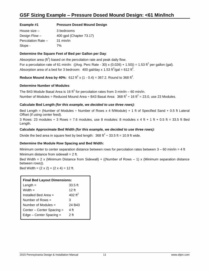
GSF Sizing Example – Pressure Dosed Mound Design: <61 Min/Inch
Example #1 Pressure Dosed Mound Design
House size – 3 bedrooms
Design Flow – 400 gpd (Chapter 73.17)
Percolation Rate – 31 min/in
Slope - 7%
Determine the Square Feet of Bed per Gallon per Day:
Absorption area (ft2) based on the percolation rate and peak daily flow.
For a percolation rate of 61 min/in: ((Avg. Perc Rate - 30) x (0.026) + 1.50)) = 1.53 ft2 per gallon (gal).
Absorption area of a bed for 3 bedroom: 400 gal/day x 1.53 ft2/gal = 612 ft
2.
Reduce Mound Area by 40%: 612 ft2 x (1 - 0.4) = 367.2. Round to 368 ft
2.
Determine Number of Modules:
The B43 Module Basal Area is 16 ft2 for percolation rates from 3 min/in – 60 min/in.
Number of Modules = Reduced Mound Area ÷ B43 Basal Area: 368 ft2 ÷ 16 ft
2 = 23.0, use 23 Modules.
Calculate Bed Length (for this example, we decided to use three rows):
Bed Length = (Number of Modules ÷ Number of Rows x 4 ft/Module) + 1 ft of Specified Sand + 0.5 ft Lateral Offset (if using center feed).
3 Rows: 23 modules ÷ 3 Rows = 7.6 modules, use 8 modules: 8 modules x 4 ft + 1 ft + 0.5 ft = 33.5 ft Bed Length.
Calculate Approximate Bed Width (for this example, we decided to use three rows):
Divide the bed area in square feet by bed length: 368 ft2 ÷ 33.5 ft = 10.9 ft wide.
Determine the Module Row Spacing and Bed Width:
Minimum center to center separation distance between rows for percolation rates between 3 – 60 min/in = 4 ft
Minimum distance from sidewall = 2 ft.
Bed Width = 2 x (Minimum Distance from Sidewall) + ((Number of Rows – 1) x (Minimum separation distance between rows)).
Bed Width = (2 x 2) + (2 x 4) = 12 ft.
Final Bed Layout Dimensions:
Length = 33.5 ft
Width = 12 ft
Installed Bed Area = 402 ft2
Number of Rows = 3
Number of Modules = 24 B43
Center – Center Spacing = 4 ft
Edge – Center Spacing = 2 ft
2015 Pennsylvania Design & Installation Manual 12 www.eljen.com
GSF Sizing Example – Pressure Dosed Mound Design: <61 Min/Inch
FIGURE 5: B43 PRESSURE DOSED CENTRAL MANIFOLD MOUND DESIGN PLAN VIEW – 3 BEDROOMS – 31 MIN/INCH
SPECIFIED SAND
SEPTIC
TANK
3" MIN
33.5'
6" MIN
PRESSURE LINE PER CODE
4" DISTRIBUTION PIPE
PUMP
CHAMBER
4'
12'
2'
6"
B43 / 36"
FIGURE 6: B43 PRESSURE DOSED END FEED MOUND DESIGN – PLAN VIEW 3 BEDROOMS – 31 MIN/INCH
SPECIFIED SAND
SEPTIC
TANK
33'
PRESSURE LINE PER CODE
4" DISTRIBUTION PIPE
PUMP
CHAMBER
6"
B43 / 36"
12'
2' 4'

2015 Pennsylvania Design & Installation Manual 13 www.eljen.com
GSF Sizing Example – Pressure Dosed Mound Design: <61 Min/Inch
FIGURE 7: B43 PRESSURE DOSED MOUND DESIGN – CROSS SECTION 3 BEDROOMS – 31 MIN/INCH
SPECIFIED SAND
1
1
8"
12" 2
36"
12"
12'
12"
NOTE: GSF Modules can be installed on a level pad or “stepped” as shown above. For a level example see Figure 14.
Lateral can be greater than 1 foot away from the upslope edge of sand bed for sloped designs.
2015 Pennsylvania Design & Installation Manual 14 www.eljen.com
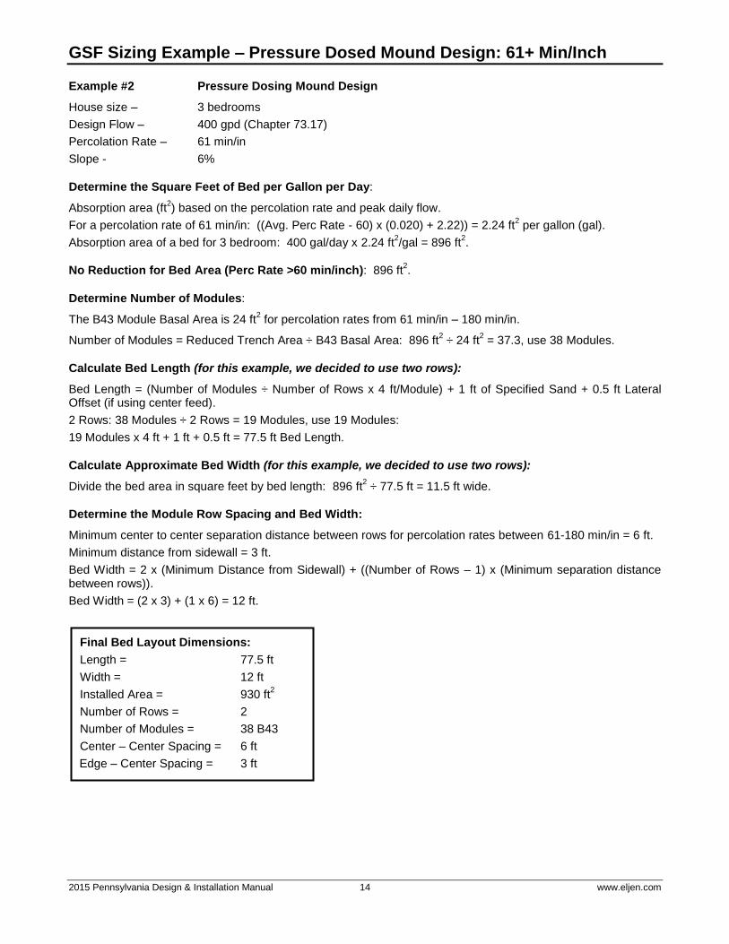
GSF Sizing Example – Pressure Dosed Mound Design: 61+ Min/Inch
Example #2 Pressure Dosing Mound Design
House size – 3 bedrooms
Design Flow – 400 gpd (Chapter 73.17)
Percolation Rate – 61 min/in
Slope - 6%
Determine the Square Feet of Bed per Gallon per Day:
Absorption area (ft2) based on the percolation rate and peak daily flow.
For a percolation rate of 61 min/in: ((Avg. Perc Rate - 60) x (0.020) + 2.22)) = 2.24 ft2 per gallon (gal).
Absorption area of a bed for 3 bedroom: 400 gal/day x 2.24 ft2/gal = 896 ft
2.
No Reduction for Bed Area (Perc Rate >60 min/inch): 896 ft2.
Determine Number of Modules:
The B43 Module Basal Area is 24 ft2 for percolation rates from 61 min/in – 180 min/in.
Number of Modules = Reduced Trench Area ÷ B43 Basal Area: 896 ft2 ÷ 24 ft
2 = 37.3, use 38 Modules.
Calculate Bed Length (for this example, we decided to use two rows):
Bed Length = (Number of Modules ÷ Number of Rows x 4 ft/Module) + 1 ft of Specified Sand + 0.5 ft Lateral Offset (if using center feed).
2 Rows: 38 Modules ÷ 2 Rows = 19 Modules, use 19 Modules:
19 Modules x 4 ft + 1 ft + 0.5 ft = 77.5 ft Bed Length.
Calculate Approximate Bed Width (for this example, we decided to use two rows):
Divide the bed area in square feet by bed length: 896 ft2 ÷ 77.5 ft = 11.5 ft wide.
Determine the Module Row Spacing and Bed Width:
Minimum center to center separation distance between rows for percolation rates between 61-180 min/in = 6 ft.
Minimum distance from sidewall = 3 ft.
Bed Width = 2 x (Minimum Distance from Sidewall) + ((Number of Rows – 1) x (Minimum separation distance between rows)).
Bed Width = (2 x 3) + (1 x 6) = 12 ft.
Final Bed Layout Dimensions:
Length = 77.5 ft
Width = 12 ft
Installed Area = 930 ft2
Number of Rows = 2
Number of Modules = 38 B43
Center – Center Spacing = 6 ft
Edge – Center Spacing = 3 ft

2015 Pennsylvania Design & Installation Manual 15 www.eljen.com
GSF Sizing Example – Pressure Dosed Mound Design: 61+ Min/Inch
FIGURE 8: B43 PRESSURE DOSED CENTRAL MANIFOLD MOUND DESIGN PLAN VIEW – 3 BEDROOMS – 61 MIN/INCH
SEPTIC
TANKSPECIFIED SAND
PUMP
CHAMBER6"
18"
B43 / 36"
3" MIN
77.5'
3'
6'12'
6" MIN
2 INCH PRESSURE LINE INSIDE 4 INCH DISTRIBUTION PIPE
END CAP
FIGURE 9: B43 PRESSURE DOSED END FEED MOUND DESIGN – PLAN VIEW 3 BEDROOMS – 61 MIN/INCH
SEPTIC
TANKSPECIFIED SAND
PUMP
CHAMBER
12'6'
77'
6"
B43 / 36"
18"
36"

2015 Pennsylvania Design & Installation Manual 16 www.eljen.com
GSF Sizing Example – Pressure Dosed Mound Design: 61+ Min/Inch
FIGURE 10: B43 PRESSURE DOSED MOUND DESIGN – CROSS SECTION 3 BEDROOMS – 61 MIN/INCH
SPECIFIED SAND
1
1
8"
12"12"
2
318" 36"18"
NOTE: GSF Modules can be installed on a level pad or “stepped” as shown above. For a level example see Figure 14.
Lateral can be greater than 1 foot away from the upslope edge of sand bed for sloped designs.
2015 Pennsylvania Design & Installation Manual 17 www.eljen.com
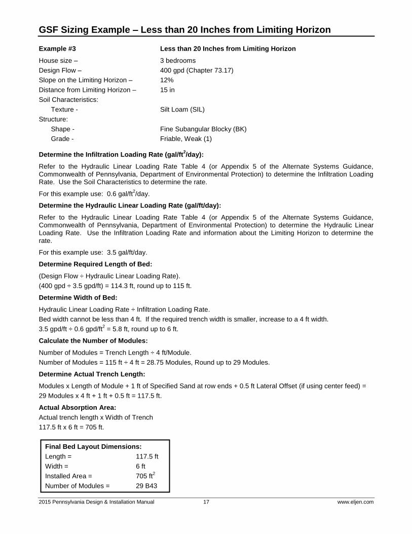
GSF Sizing Example – Less than 20 Inches from Limiting Horizon
Example #3 Less than 20 Inches from Limiting Horizon
House size – 3 bedrooms
Design Flow – 400 gpd (Chapter 73.17)
Slope on the Limiting Horizon – 12%
Distance from Limiting Horizon – 15 in
Soil Characteristics:
Texture - Silt Loam (SIL)
Structure:
Shape - Fine Subangular Blocky (BK)
Grade - Friable, Weak (1)
Determine the Infiltration Loading Rate (gal/ft2/day):
Refer to the Hydraulic Linear Loading Rate Table 4 (or Appendix 5 of the Alternate Systems Guidance, Commonwealth of Pennsylvania, Department of Environmental Protection) to determine the Infiltration Loading Rate. Use the Soil Characteristics to determine the rate.
For this example use: 0.6 gal/ft2/day.
Determine the Hydraulic Linear Loading Rate (gal/ft/day):
Refer to the Hydraulic Linear Loading Rate Table 4 (or Appendix 5 of the Alternate Systems Guidance, Commonwealth of Pennsylvania, Department of Environmental Protection) to determine the Hydraulic Linear Loading Rate. Use the Infiltration Loading Rate and information about the Limiting Horizon to determine the rate.
For this example use: 3.5 gal/ft/day.
Determine Required Length of Bed:
(Design Flow ÷ Hydraulic Linear Loading Rate).
(400 gpd ÷ 3.5 gpd/ft) = 114.3 ft, round up to 115 ft.
Determine Width of Bed:
Hydraulic Linear Loading Rate ÷ Infiltration Loading Rate.
Bed width cannot be less than 4 ft. If the required trench width is smaller, increase to a 4 ft width.
3.5 gpd/ft ÷ 0.6 gpd/ft2 = 5.8 ft, round up to 6 ft.
Calculate the Number of Modules:
Number of Modules = Trench Length ÷ 4 ft/Module.
Number of Modules = 115 ft ÷ 4 ft = 28.75 Modules, Round up to 29 Modules.
Determine Actual Trench Length:
Modules x Length of Module + 1 ft of Specified Sand at row ends + 0.5 ft Lateral Offset (if using center feed) =
29 Modules x 4 ft + 1 ft + 0.5 ft = 117.5 ft.
Actual Absorption Area:
Actual trench length x Width of Trench
117.5 ft x 6 ft = 705 ft.
Final Bed Layout Dimensions:
Length = 117.5 ft
Width = 6 ft
Installed Area = 705 ft2
Number of Modules = 29 B43

2015 Pennsylvania Design & Installation Manual 18 www.eljen.com
GSF Sizing Example – Less than 20 Inches from Limiting Horizon
FIGURE 11: LESS THAN 20 INCHES FROM LIMITING HORIZON PLAN VIEW – CENTER FED
36"
4'
SEPTIC
TANK
SPECIFIED SAND
117.5'
6'
PUMP CHAMBER
6" MINON ENDS
4" DISTRIBUTION PIPE
PRESSURE LINE PER CODE
FIGURE 12: LESS THAN 20 INCHES FROM LIMITING HORIZON
PLAN VIEW – END FED
SEPTIC
TANK
PUMP CHAMBER
PRESSURE LINE PER CODE
SPECIFIED SAND 4" DISTRIBUTION PIPE
6'36"
6" MINON ENDS
117'
48"
FIGURE 13: LESS THAN 20 INCHES FROM LIMITING HORIZON CROSS SECTION
312
112" MIN
8" MIN6.0'
2.5'
SPECIFIED SAND
12 % SLOPE
6" MIN
NOTE: Offset edge of GSF module a minimum of 6 inches from the upslope edge of sand layer. Place the remaining required sand (depending on width specified by soil scientist) on the downslope side of the GSF. See example above.
2015 Pennsylvania Design & Installation Manual 19 www.eljen.com
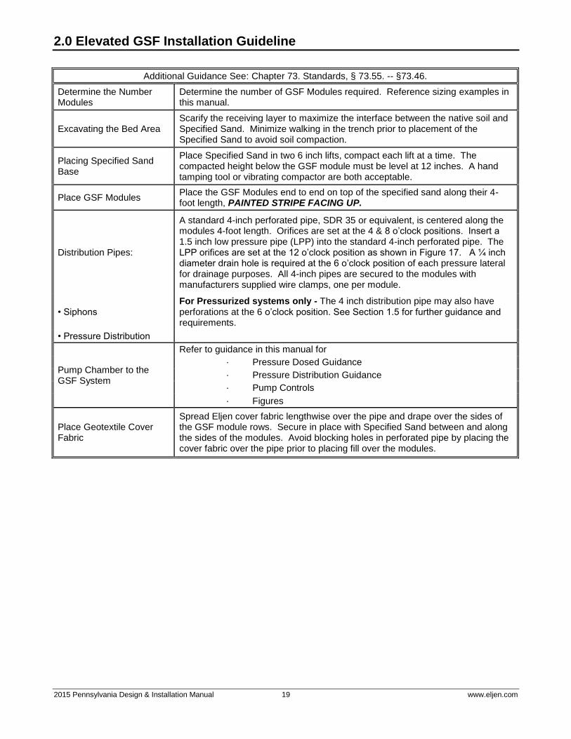
2.0 Elevated GSF Installation Guideline
Additional Guidance See: Chapter 73. Standards, § 73.55. -- §73.46.
Determine the Number Modules
Determine the number of GSF Modules required. Reference sizing examples in this manual.
Excavating the Bed Area Scarify the receiving layer to maximize the interface between the native soil and Specified Sand. Minimize walking in the trench prior to placement of the Specified Sand to avoid soil compaction.
Placing Specified Sand Base
Place Specified Sand in two 6 inch lifts, compact each lift at a time. The compacted height below the GSF module must be level at 12 inches. A hand tamping tool or vibrating compactor are both acceptable.
Place GSF Modules Place the GSF Modules end to end on top of the specified sand along their 4-foot length, PAINTED STRIPE FACING UP.
Distribution Pipes:
A standard 4-inch perforated pipe, SDR 35 or equivalent, is centered along the modules 4-foot length. Orifices are set at the 4 & 8 o’clock positions. Insert a 1.5 inch low pressure pipe (LPP) into the standard 4-inch perforated pipe. The LPP orifices are set at the 12 o’clock position as shown in Figure 17. A ¼ inch diameter drain hole is required at the 6 o’clock position of each pressure lateral for drainage purposes. All 4-inch pipes are secured to the modules with manufacturers supplied wire clamps, one per module.
• Siphons For Pressurized systems only - The 4 inch distribution pipe may also have perforations at the 6 o’clock position. See Section 1.5 for further guidance and requirements.
• Pressure Distribution
Pump Chamber to the GSF System
Refer to guidance in this manual for
· Pressure Dosed Guidance
· Pressure Distribution Guidance
· Pump Controls
· Figures
Place Geotextile Cover Fabric
Spread Eljen cover fabric lengthwise over the pipe and drape over the sides of the GSF module rows. Secure in place with Specified Sand between and along the sides of the modules. Avoid blocking holes in perforated pipe by placing the cover fabric over the pipe prior to placing fill over the modules.

2015 Pennsylvania Design & Installation Manual 20 www.eljen.com
3.0 In-Ground Trench Installation Guideline
Additional Guidance See: Chapter 73. Standards, § 73.52
Determine the Number Modules
Determine the number of GSF Modules required. Reference sizing examples in this manual.
Determine Trench Dimensions
Calculate the length, width and number of trenches using the sizing examples. The maximum single trench length in Pennsylvania is 100 ft.
Plan all Drainage Requirements
Plan all drainage requirements up-slope of the system. Set soil grades to ensure that storm water drainage and ground water is diverted away from the absorption area once the system is complete.
Excavating the Trench Area
Scarify the receiving layer to maximize interface between the native soil and Specified Sand. Minimize walking in the trench prior to placement of the Specified Sand to avoid soil compaction.
Placing Specified Sand Base
Place Specified Sand in two 6 inch lifts into the bed, compact each lift at a time. The compacted height below the GSF module must be level at 12 inches. A hand tamping tool or vibrating compactor is acceptable.
Place GSF Modules Place the GSF Modules end to end on top of the specified sand along their 4-foot length, PAINTED STRIPE FACING UP.
Distribution Pipes: Gravity
A standard 4-inch perforated pipe, SDR 35 or equivalent, is centered along the modules 4-foot length. Orifices are set at the 4 & 8 o’clock positions. All 4-inch pipes are secured with manufacturers supplied wire clamps, one per module. Section 1.5 of this manual has more information on pipe selection.
Distribution Pipes: Pressure Distribution Systems
A standard 4-inch perforated pipe, SDR 35 or equivalent, is centered along the modules 4-foot length. Orifices are set at the 4 & 8 o’clock positions. Insert a 1.5 inch low pressure pipe (LPP) into the standard 4-inch perforated pipe. The LPP orifices are set at the 12 o’clock position as shown in Figure 17. A ¼ inch diameter drain hole is required at the 6 o’clock position of each pressure lateral for drainage purposes. All 4-inch pipes are secured to the modules with manufacturers supplied wire clamps, one per module.
For Pressurized systems only - The 4 inch distribution pipe may also have perforations at the 6 o’clock position. See Section 1.5 for further guidance and requirements.
Place Geotextile Cover Fabric
Spread Eljen supplied cover fabric lengthwise over the pipe and drape over the sides of the GSF module rows. Secure in place with Specified Sand between and along the sides of the modules. Avoid blocking holes in perforated pipe by placing the cover fabric over the pipe prior to placing fill over the modules.
Placing Specified Sand after Cover Fabric is in place
Place 6 inches minimum of Specified Sand along both sides of the modules edge when percolation rates are between 3 – 60 min/in. Place 18 inches of Specified Sand along both sides of the modules edge when percolation rates are between 61 – 180 min/in. A minimum of 6 inches of Specified Sand is placed at the beginning and end of each row.
Backfilling the System
Complete backfill with topsoil, a minimum of 8 inches over the GSF modules. Backfill exceeding 18 inches requires venting at the distal end of the system. Fill must be clean, porous and devoid of rocks. Do not use wheeled equipment over the system during backfill operation. A light track machine may be used with extreme caution, avoiding crushing or shifting of pipe assembly. Divert surface runoff. Finish grade to prevent surface ponding. Use backfill material that is soil suitable for the growth of vegetation, and be seeded to control erosion.
Place Geotextile Cover Fabric
Spread Eljen cover fabric lengthwise over the pipe and drape over the sides of the GSF module rows. Secure in place with Specified Sand between and along the sides of the modules. Avoid blocking holes in perforated pipe by placing the cover fabric over the pipe prior to placing fill over the modules.
2015 Pennsylvania Design & Installation Manual 21 www.eljen.com
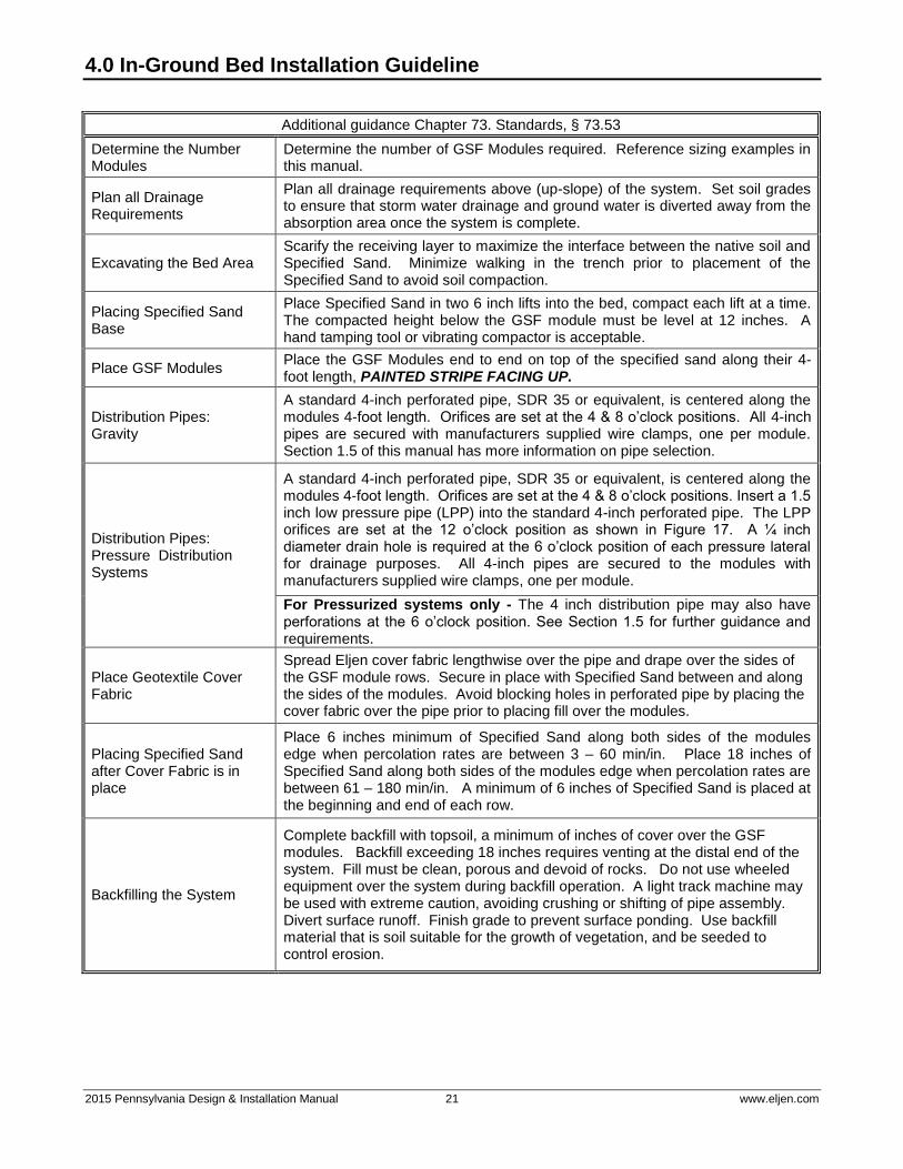
4.0 In-Ground Bed Installation Guideline
Additional guidance Chapter 73. Standards, § 73.53
Determine the Number Modules
Determine the number of GSF Modules required. Reference sizing examples in this manual.
Plan all Drainage Requirements
Plan all drainage requirements above (up-slope) of the system. Set soil grades to ensure that storm water drainage and ground water is diverted away from the absorption area once the system is complete.
Excavating the Bed Area Scarify the receiving layer to maximize the interface between the native soil and Specified Sand. Minimize walking in the trench prior to placement of the Specified Sand to avoid soil compaction.
Placing Specified Sand Base
Place Specified Sand in two 6 inch lifts into the bed, compact each lift at a time. The compacted height below the GSF module must be level at 12 inches. A hand tamping tool or vibrating compactor is acceptable.
Place GSF Modules Place the GSF Modules end to end on top of the specified sand along their 4-foot length, PAINTED STRIPE FACING UP.
Distribution Pipes: Gravity
A standard 4-inch perforated pipe, SDR 35 or equivalent, is centered along the modules 4-foot length. Orifices are set at the 4 & 8 o’clock positions. All 4-inch pipes are secured with manufacturers supplied wire clamps, one per module. Section 1.5 of this manual has more information on pipe selection.
Distribution Pipes: Pressure Distribution Systems
A standard 4-inch perforated pipe, SDR 35 or equivalent, is centered along the modules 4-foot length. Orifices are set at the 4 & 8 o’clock positions. Insert a 1.5 inch low pressure pipe (LPP) into the standard 4-inch perforated pipe. The LPP orifices are set at the 12 o’clock position as shown in Figure 17. A ¼ inch diameter drain hole is required at the 6 o’clock position of each pressure lateral for drainage purposes. All 4-inch pipes are secured to the modules with manufacturers supplied wire clamps, one per module.
For Pressurized systems only - The 4 inch distribution pipe may also have perforations at the 6 o’clock position. See Section 1.5 for further guidance and requirements.
Place Geotextile Cover Fabric
Spread Eljen cover fabric lengthwise over the pipe and drape over the sides of the GSF module rows. Secure in place with Specified Sand between and along the sides of the modules. Avoid blocking holes in perforated pipe by placing the cover fabric over the pipe prior to placing fill over the modules.
Placing Specified Sand after Cover Fabric is in place
Place 6 inches minimum of Specified Sand along both sides of the modules edge when percolation rates are between 3 – 60 min/in. Place 18 inches of Specified Sand along both sides of the modules edge when percolation rates are between 61 – 180 min/in. A minimum of 6 inches of Specified Sand is placed at the beginning and end of each row.
Backfilling the System
Complete backfill with topsoil, a minimum of inches of cover over the GSF modules. Backfill exceeding 18 inches requires venting at the distal end of the system. Fill must be clean, porous and devoid of rocks. Do not use wheeled equipment over the system during backfill operation. A light track machine may be used with extreme caution, avoiding crushing or shifting of pipe assembly. Divert surface runoff. Finish grade to prevent surface ponding. Use backfill material that is soil suitable for the growth of vegetation, and be seeded to control erosion.
2015 Pennsylvania Design & Installation Manual 22 www.eljen.com
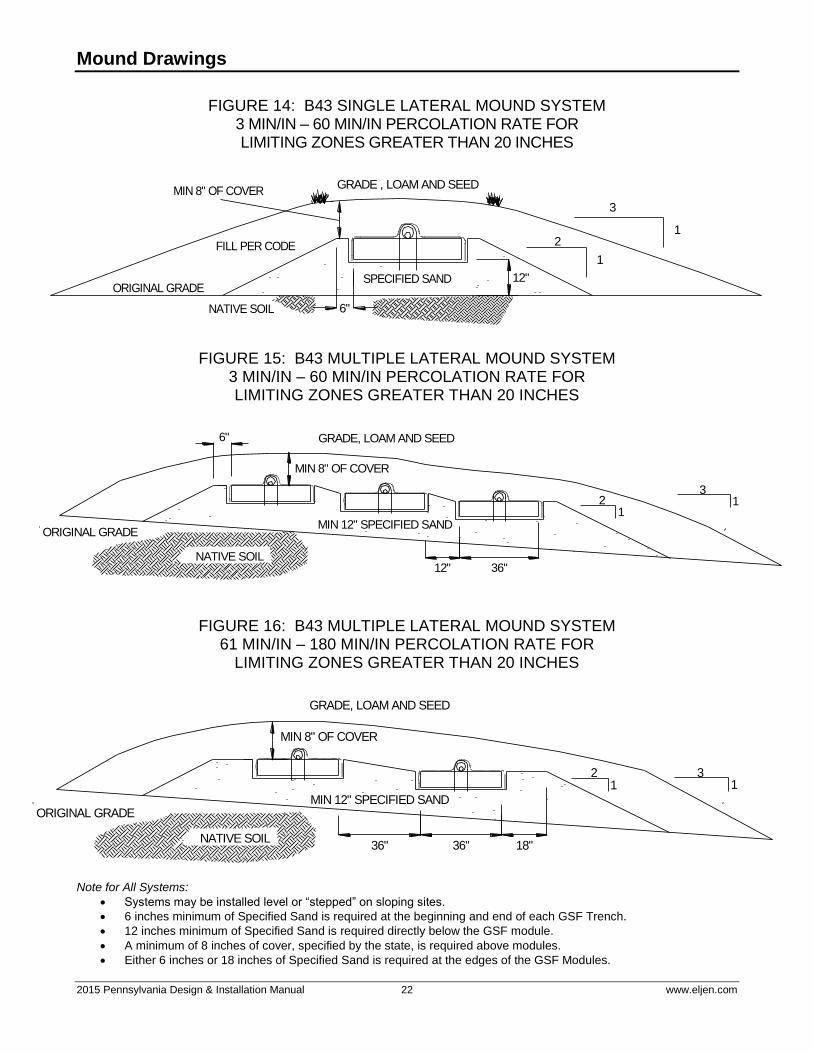
Mound Drawings
FIGURE 14: B43 SINGLE LATERAL MOUND SYSTEM 3 MIN/IN – 60 MIN/IN PERCOLATION RATE FOR LIMITING ZONES GREATER THAN 20 INCHES
GRADE , LOAM AND SEED
3
12
1
NATIVE SOIL
MIN 8" OF COVER
SPECIFIED SANDORIGINAL GRADE
12"
FILL PER CODE
6"
FIGURE 15: B43 MULTIPLE LATERAL MOUND SYSTEM 3 MIN/IN – 60 MIN/IN PERCOLATION RATE FOR LIMITING ZONES GREATER THAN 20 INCHES
6"
MIN 12" SPECIFIED SANDORIGINAL GRADE
GRADE, LOAM AND SEED
MIN 8" OF COVER
312
1
NATIVE SOIL36"12"
FIGURE 16: B43 MULTIPLE LATERAL MOUND SYSTEM 61 MIN/IN – 180 MIN/IN PERCOLATION RATE FOR
LIMITING ZONES GREATER THAN 20 INCHES
MIN 12" SPECIFIED SANDORIGINAL GRADE
GRADE, LOAM AND SEED
MIN 8" OF COVER
31
21
NATIVE SOIL18"36"36"
Note for All Systems:
Systems may be installed level or “stepped” on sloping sites.
6 inches minimum of Specified Sand is required at the beginning and end of each GSF Trench.
12 inches minimum of Specified Sand is required directly below the GSF module.
A minimum of 8 inches of cover, specified by the state, is required above modules.
Either 6 inches or 18 inches of Specified Sand is required at the edges of the GSF Modules.
2015 Pennsylvania Design & Installation Manual 23 www.eljen.com
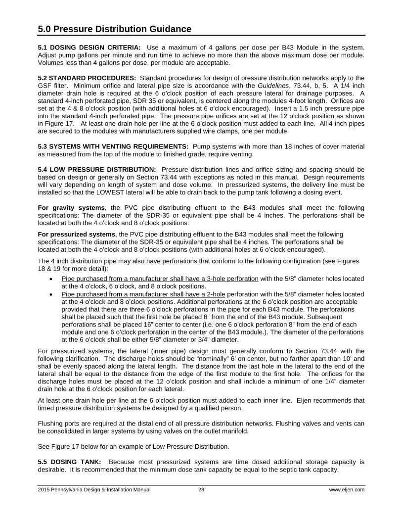
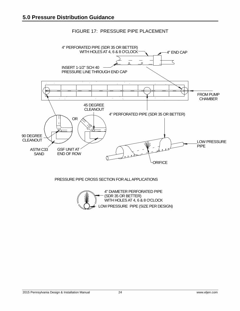
5.0 Pressure Distribution Guidance
5.1 DOSING DESIGN CRITERIA: Use a maximum of 4 gallons per dose per B43 Module in the system. Adjust pump gallons per minute and run time to achieve no more than the above maximum dose per module. Volumes less than 4 gallons per dose, per module are acceptable.
5.2 STANDARD PROCEDURES: Standard procedures for design of pressure distribution networks apply to the GSF filter. Minimum orifice and lateral pipe size is accordance with the Guidelines, 73.44, b, 5. A 1/4 inch diameter drain hole is required at the 6 o’clock position of each pressure lateral for drainage purposes. A standard 4-inch perforated pipe, SDR 35 or equivalent, is centered along the modules 4-foot length. Orifices are set at the 4 & 8 o’clock position (with additional holes at 6 o’clock encouraged). Insert a 1.5 inch pressure pipe into the standard 4-inch perforated pipe. The pressure pipe orifices are set at the 12 o’clock position as shown in Figure 17. At least one drain hole per line at the 6 o’clock position must added to each line. All 4-inch pipes are secured to the modules with manufacturers supplied wire clamps, one per module.
5.3 SYSTEMS WITH VENTING REQUIREMENTS: Pump systems with more than 18 inches of cover material as measured from the top of the module to finished grade, require venting.
5.4 LOW PRESSURE DISTRIBUTION: Pressure distribution lines and orifice sizing and spacing should be based on design or generally on Section 73.44 with exceptions as noted in this manual. Design requirements will vary depending on length of system and dose volume. In pressurized systems, the delivery line must be installed so that the LOWEST lateral will be able to drain back to the pump tank following a dosing event.
For gravity systems, the PVC pipe distributing effluent to the B43 modules shall meet the following specifications: The diameter of the SDR-35 or equivalent pipe shall be 4 inches. The perforations shall be located at both the 4 o’clock and 8 o’clock positions.
For pressurized systems, the PVC pipe distributing effluent to the B43 modules shall meet the following specifications: The diameter of the SDR-35 or equivalent pipe shall be 4 inches. The perforations shall be located at both the 4 o’clock and 8 o’clock positions (with additional holes at 6 o’clock encouraged).
The 4 inch distribution pipe may also have perforations that conform to the following configuration (see Figures 18 & 19 for more detail):
• Pipe purchased from a manufacturer shall have a 3-hole perforation with the 5/8” diameter holes located at the 4 o’clock, 6 o’clock, and 8 o’clock positions.
• Pipe purchased from a manufacturer shall have a 2-hole perforation with the 5/8” diameter holes located at the 4 o’clock and 8 o’clock positions. Additional perforations at the 6 o’clock position are acceptable provided that there are three 6 o’clock perforations in the pipe for each B43 module. The perforations shall be placed such that the first hole be placed 8” from the end of the B43 module. Subsequent perforations shall be placed 16” center to center (i.e. one 6 o’clock perforation 8” from the end of each module and one 6 o’clock perforation in the center of the B43 module.). The diameter of the perforations at the 6 o’clock shall be either 5/8” diameter or 3/4" diameter.
For pressurized systems, the lateral (inner pipe) design must generally conform to Section 73.44 with the following clarification. The discharge holes should be “nominally” 6’ on center, but no farther apart than 10’ and shall be evenly spaced along the lateral length. The distance from the last hole in the lateral to the end of the lateral shall be equal to the distance from the edge of the first module to the first hole. The orifices for the discharge holes must be placed at the 12 o’clock position and shall include a minimum of one 1/4” diameter drain hole at the 6 o’clock position for each lateral.
At least one drain hole per line at the 6 o’clock position must added to each inner line. Eljen recommends that timed pressure distribution systems be designed by a qualified person.
Flushing ports are required at the distal end of all pressure distribution networks. Flushing valves and vents can be consolidated in larger systems by using valves on the outlet manifold.
See Figure 17 below for an example of Low Pressure Distribution.
5.5 DOSING TANK: Because most pressurized systems are time dosed additional storage capacity is desirable. It is recommended that the minimum dose tank capacity be equal to the septic tank capacity.
2015 Pennsylvania Design & Installation Manual 24 www.eljen.com
5.0 Pressure Distribution Guidance
FIGURE 17: PRESSURE PIPE PLACEMENT
FROM PUMPCHAMBER
4" PERFORATED PIPE (SDR 35 OR BETTER)
90 DEGREECLEANOUT
GSF UNIT ATEND OF ROW
ASTM C33SAND
LOW PRESSUREPIPE
4" DIAMETER PERFORATED PIPE(SDR 35 OR BETTER)WITH HOLES AT 4, 6 & 8 O'CLOCK
LOW PRESSURE PIPE (SIZE PER DESIGN)
PRESSURE PIPE CROSS SECTION FOR ALL APPLICATIONS
ORIFICE
4" PERFORATED PIPE (SDR 35 OR BETTER)WITH HOLES AT 4, 6 & 8 O'CLOCK 4" END CAP
INSERT 1-1/2" SCH 40 PRESSURE LINE THROUGH END CAP
45 DEGREECLEANOUT
OR

2015 Pennsylvania Design & Installation Manual 25 www.eljen.com
5.0 Pressure Distribution Guidance
FIGURE 18: ALTERNATIVE HOLE PLACEMENT FOR 4 INCH DISTRIBUTION PIPE PRESSURIZED SYSTEMS ONLY – MANUFACTURED 3 HOLE PIPE
B43 MODULEB43 MODULE B43 MODULE
5" 5" 5" 5" 5"5" 5" 5"
PERFORATIONS AT6:00 POSITION
FIGURE 19: ALTERNATIVE HOLE PLACEMENT FOR 4 INCH DISTRIBUTION PIPE PRESSURIZED SYSTEMS ONLY – INSTALLER DRILLED PIPE
8"
B43 MODULEB43 MODULE B43 MODULE
8" 16"16" 8" 8"
INSTALLER DRILLS PERFORATIONSAT 6:00 POSITION MARKED FROM EDGE OF EACH MODULE
2015 Pennsylvania Design & Installation Manual 26 www.eljen.com
5.0 Pressure Distribution Guidance
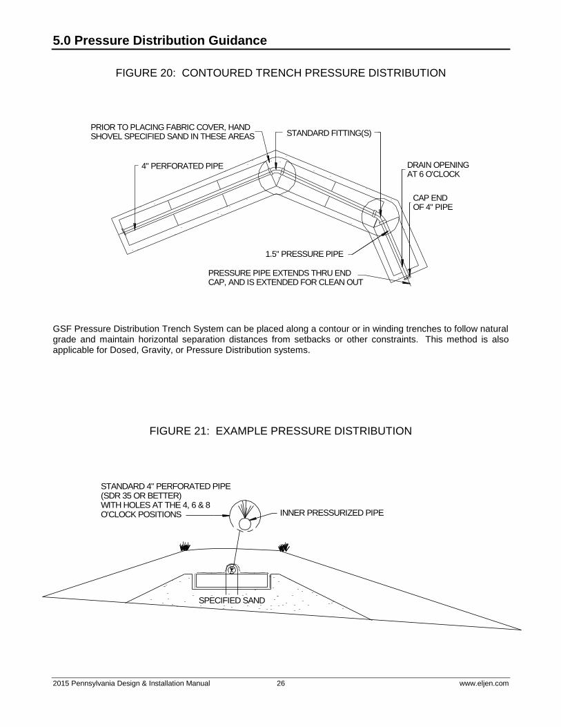
FIGURE 20: CONTOURED TRENCH PRESSURE DISTRIBUTION
PRIOR TO PLACING FABRIC COVER, HANDSHOVEL SPECIFIED SAND IN THESE AREAS STANDARD FITTING(S)
4" PERFORATED PIPE
1.5" PRESSURE PIPE
PRESSURE PIPE EXTENDS THRU ENDCAP, AND IS EXTENDED FOR CLEAN OUT
DRAIN OPENING AT 6 O'CLOCK
CAP ENDOF 4" PIPE
GSF Pressure Distribution Trench System can be placed along a contour or in winding trenches to follow natural grade and maintain horizontal separation distances from setbacks or other constraints. This method is also applicable for Dosed, Gravity, or Pressure Distribution systems.
FIGURE 21: EXAMPLE PRESSURE DISTRIBUTION
SPECIFIED SAND
INNER PRESSURIZED PIPE
STANDARD 4" PERFORATED PIPE(SDR 35 OR BETTER)WITH HOLES AT THE 4, 6 & 8O'CLOCK POSITIONS
2015 Pennsylvania Design & Installation Manual 27 www.eljen.com
5.0 Pressure Distribution Guidance
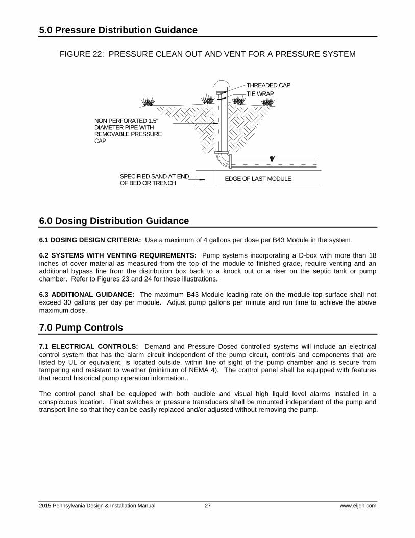
FIGURE 22: PRESSURE CLEAN OUT AND VENT FOR A PRESSURE SYSTEM
EDGE OF LAST MODULE
NON PERFORATED 1.5"DIAMETER PIPE WITHREMOVABLE PRESSURECAP
SPECIFIED SAND AT ENDOF BED OR TRENCH
THREADED CAP
TIE WRAP
6.0 Dosing Distribution Guidance
6.1 DOSING DESIGN CRITERIA: Use a maximum of 4 gallons per dose per B43 Module in the system. 6.2 SYSTEMS WITH VENTING REQUIREMENTS: Pump systems incorporating a D-box with more than 18 inches of cover material as measured from the top of the module to finished grade, require venting and an additional bypass line from the distribution box back to a knock out or a riser on the septic tank or pump chamber. Refer to Figures 23 and 24 for these illustrations. 6.3 ADDITIONAL GUIDANCE: The maximum B43 Module loading rate on the module top surface shall not exceed 30 gallons per day per module. Adjust pump gallons per minute and run time to achieve the above maximum dose.
7.0 Pump Controls
7.1 ELECTRICAL CONTROLS: Demand and Pressure Dosed controlled systems will include an electrical control system that has the alarm circuit independent of the pump circuit, controls and components that are listed by UL or equivalent, is located outside, within line of sight of the pump chamber and is secure from tampering and resistant to weather (minimum of NEMA 4). The control panel shall be equipped with features that record historical pump operation information..
The control panel shall be equipped with both audible and visual high liquid level alarms installed in a conspicuous location. Float switches or pressure transducers shall be mounted independent of the pump and transport line so that they can be easily replaced and/or adjusted without removing the pump.
2015 Pennsylvania Design & Installation Manual 28 www.eljen.com
8.0 System Ventilation
8.1 SYSTEM VENTILATION: Air vents are required on all absorption systems located under impervious surfaces or systems with more than 18 inches of cover material as measured from the top of the GSF Module to finished grade. This will ensure proper aeration of the modules and sand filter. Under normal operating conditions, only a fraction of the filter is in use. The unused portion of the GSF remains open for intermittent peak flows and the transfer of air. The extension of the distribution pipe to the vent provides adequate delivery of air into the GSF system, as shown in Figures 23 & 24.
To maintain this airflow and fully aerate the GSF system, it is important that air vents are located only on the distal end of the GSF pipe network.
If a pressure or demand dosed system with a D-box is specified with greater than 18 inches of cover, an additional 2-inch minimum airline must be extended from the GSF D-box back to a knockout or riser on the septic tank or pump chamber. This maintains the continuity of airflow from the field into the house plumbing.
In a pressure dosed system not incorporating a D-box, or in a gravity fed GSF system, the vent is usually a 4-inch diameter pipe extended to grade or to a convenient location behind shrubs, as shown in Figure 22. Corrugated pipe can be used with the placement and grade such that any condensation that may accumulate in the pipe does not fill and thus close off this line. If the vent is extended, the pipe must not drain effluent and must have an invert higher than the system.
System Ventilation Example Drawings
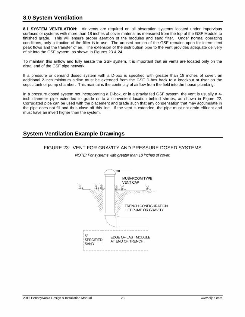
FIGURE 23: VENT FOR GRAVITY AND PRESSURE DOSED SYSTEMS
NOTE: For systems with greater than 18 inches of cover.
6" SPECIFIEDSAND
EDGE OF LAST MODULEAT END OF TRENCH
TRENCH CONFIGURATIONLIFT PUMP OR GRAVITY
MUSHROOM TYPEVENT CAP

2015 Pennsylvania Design & Installation Manual 29 www.eljen.com
System Ventilation Example Drawings
FIGURE 24: GSF WITH 4” VENT EXTENDED TO CONVENIENT LOCATION
NOTE: For systems with greater than 18 inches of cover.
SHRUB
GSF MODULES
MOUNDED BACKFILL OVER MODULES
COVER FABRIC NOT SHOWN OVER DISTRIBUTION PIPE AND MODULES
CLEAN BACKFILLFINISHED GRADE
SPECIFIED SAND

2015 Pennsylvania Design & Installation Manual 30 www.eljen.com
TABLE 5: HYDRAULIC LINEAR LOADING RATE TABLE
Hydraulic Liner Loading Rate, gal/ft/d
Slope
Soil Characteristics
Infiltration
Loading Rate,
gal/ft2/d
0-4% 5-9% >10%
Texture
Structure Infiltration Distance,
Inch
Infiltration Distance,
Inch
Infiltration Distance,
Inch
Shape Grade 10-12 12-20 10-12 12-20 10-12 12-20
COS, S, LCOS, LS -- 0SG 1.6 4.0 5.0 5.0 6.0 6.0 7.0
FS, VFS, LFS, LVFS -- 0SG 1.0 3.5 4.5 4.0 5.0 5.0 6.0
CSL, SL
-- 0M 0.6 3.0 3.5 3.6 4.1 5.0 6.0
PL 1 0.5 3.0 3.5 3.6 4.1 4.0 5.0
2, 3
PR/BK
/GR
1 0.7 3.5 4.5 4.0 5.0 5.0 6.0
2, 3 1.0 3.5 4.5 4.0 5.0 5.0 6.0
FSL, VFSL
-- 0M 0.5 2.0 2.3 2.4 2.7 2.7 3.2
PL 1, 2, 3
PR/BK
/GR
1 0.6 3.0 3.5 3.3 3.8 3.6 4.1
2, 3 0.8 3.3 3.8 3.6 4.1 3.9 4.4
L
-- 0M 0.5 2.0 2.3 2.4 2.7 2.7 3.2
PL 1, 2, 3
PR/BK
/GR
1 0.6 3.0 3.5 3.3 3.8 3.6 4.1
2, 3 0.8 3.3 3.8 3.6 4.1 3.9 4.4
SIL
-- 0M 0.2 2.0 2.5 2.2 2.7 2.4 2.9
PL 1, 2, 3
PR/BK
/GR
1 0.6 2.4 2.7 2.7 3.0 3.0 3.5
2, 3 0.8 2.7 3.0 3.0 3.5 3.3 3.8
SCL, CL, SICL
-- 0M
PL 1, 2, 3
PR/BK
/GR
1 0.3 2.0 2.5 2.2 2.7 2.4 2.9
2, 3 0.6 2.4 2.9 2.7 3.0 3.0 3.5
SC, C, SIC
-- 0M
PL 1, 2, 3
PR/BK
/GR
1
2, 3 0.3 2.0 2.5 2.2 2.7 2.4 2.9
Adapted from Tyler, 2000.
Width of Infiltration Field = Hydraulic Linear Loading Rate divided by Infiltration Hydraulic Loading Rate
Length of Infiltration Field = Wastewater Volume divided by Hydraulic Linear Loading Rate
2015 Pennsylvania Design & Installation Manual 31 www.eljen.com
Eljen Installation Check List
Prior to final backfill over the GSF modules, ensure that all of the installation check points listed below have been completed.
ALL SYSTEMS
1. Each line or row of the system is level.
2. Ensure that the painted white stripe is facing up on each module.
3. Verify there is a minimum of 12 inches of Specified Sand underneath each module in the system.
4. Based on the system design, verify the appropriate amount of Specified Sand is installed between
module rows in bed systems, and along the 4-foot module length in trench systems.
5. Ensure there is a minimum of 6 inches of Specified Sand at the beginning and end of module rows in bed or trench systems.
6. The 4-inch perforated pipe on top of the module is SDR-35 or equivalent.
7. The perforated 4-inch pipe has orifices at 4 & 8 o'clock over the modules or alternative 4, 8 and 6
o’clock positions for pressurized systems.
8. The wire clamps that fit over the 4-inch distribution pipe are installed, one per module.
9. The cover fabric is placed over the 4-inch perforated pipe, and draped over the sides of each module prior to Specified Sand placement around modules. The cover fabric shall NOT be pulled tightly over the 4-inch perforated pipe, which causes tenting.
PRESSURE DISTRIBUTION ONLY
1. In the 1.5-inch LPP, there is at least one drain hole at the 6 o’clock position.
2. The LPP has its orifices at the 12 o'clock position.
3. The 4-inch perforated pipe has holes at 4 & 8 o'clock or alternative 4, 8 and 6 o’clock positions per
designers preference.
4. Verify that there is a minimum of 3 feet of head at the terminal end of each lateral.
5. For at-grade absorption areas, verify the length and width ratio is a minimum of 4:1 for slopes ranging from 8 percent to 12 percent or 6:1 for slopes ranging 12 percent to 15 percent.
6. Verify there is minimum 2:1 approved sand slope on all sides of the aggregate.
7. Verify the berms meet the requirements of Section 73.55(b)(7), 73.55(d)(3), and 73.55(d)(4).
8. Verify the inclusion of lateral end cleanout.
ALL SYSTEMS - MAINTENANCE
1. DEP has determined that a maintenance agreement is not a requirement for Eljen permit issuance and that the manufacturer should determine the frequency of maintenance activities as specified in the Eljen System owner’s manual. Eljen recommends that the maintenance activities and frequency for Geotextile Sand Filter systems be equal to the maintenance activities and frequency specified by the local agency for Elevated Sand mounds.

125 McKee Street, East Hartford, CT 06108 • Tel: 800-444-1359 • Fax: 860-610-0427
www.eljen.com
COMPANY HISTORYEstablished in 1970, Eljen Corporation created the world’s first
prefabricated drainage system for foundation drainage and erosion control applications. In the mid-1980s, we introduced our Geotextile Sand Filter products for the passive advanced
treatment of onsite wastewater in both residential and commercial applications. Today, Eljen is a global leader in providing innovative
products and solutions for protecting our environment and public health.
COMPANY PHILOSOPHYEljen Corporation is committed to advancing the onsite industry through continuous development of innovative new products, delivering high quality products and services to our customers
at the best price, and building lasting partnerships with our employees, suppliers, and customers.
© Copyright Eljen Corporation
CORPORATIONInnovative Environmental Products & Solutions Since 1970
Printed in U.S.A. on recycled paper