Geotechnical Memorandum #1 PLANS/A8693 Cactus and Camero…Rock-like cemented deposits were...
19
Geotechnical Memorandum #1: TO: David J. O’Donnell / Boos Development West, LLC FROM: Michael C. Stojanoff, PG, PE / Terracon Consultants, Inc. DATE: November 23, 2016 RE: Cactus Street Commercial Site Northeast Corner of Cactus Avenue and Cameron Street Clark County, Nevada Terracon Project No. 64165132 The purpose of this memorandum is to present interim boring data to evaluate the hardness of materials expected to be encountered during construction excavation. The location of the subject site is shown on attached Exhibit A-1, Site Location Map. Field Explorations As part of the field exploration program, 11 soil borings were performed to characterize the subsurface soils and conditions at the referenced subject site. The approximate locations of the borings are shown on attached Exhibit A-2, Boring Location Plan. The results of the borings are presented in detail on the boring logs shown in attached Exhibits A-3 through A-13. Cemented deposits consisting of cemented alluvial sand and gravel were encountered in the borings. Cemented deposits encountered are summarized as follows: n At the proposed Jiffy Lube Building where relatively deep excavation for the auto shop bays are planned, cemented deposits were first encountered at depths ranging from 7.5 to 13 feet below ground surface (bgs). n At the proposed Gas Station and Convenience Store where relatively deep excavation for the underground fuel storage tank is planned, no fully cemented deposits were encountered. n The shallowest cemented deposits were encountered 3 feet bgs, but were relatively weak and were encountered at the proposed Fitness Center Building where deep excavation is not anticipated. n The table below provides a more detailed summary of cemented deposits encountered at the site.
Transcript of Geotechnical Memorandum #1 PLANS/A8693 Cactus and Camero…Rock-like cemented deposits were...

Geotechnical Memorandum #1:TO: David J. O’Donnell / Boos Development West, LLC
FROM: Michael C. Stojanoff, PG, PE / Terracon Consultants, Inc.
DATE: November 23, 2016
RE: Cactus Street Commercial SiteNortheast Corner of Cactus Avenue and Cameron StreetClark County, NevadaTerracon Project No. 64165132
The purpose of this memorandum is to present interim boring data to evaluate the hardness ofmaterials expected to be encountered during construction excavation. The location of the subjectsite is shown on attached Exhibit A-1, Site Location Map.
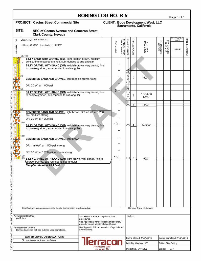
Field ExplorationsAs part of the field exploration program, 11 soil borings were performed to characterize thesubsurface soils and conditions at the referenced subject site. The approximate locations of theborings are shown on attached Exhibit A-2, Boring Location Plan. The results of the borings arepresented in detail on the boring logs shown in attached Exhibits A-3 through A-13. Cementeddeposits consisting of cemented alluvial sand and gravel were encountered in the borings.Cemented deposits encountered are summarized as follows:
n At the proposed Jiffy Lube Building where relatively deep excavation for the auto shopbays are planned, cemented deposits were first encountered at depths ranging from 7.5to 13 feet below ground surface (bgs).
n At the proposed Gas Station and Convenience Store where relatively deep excavation forthe underground fuel storage tank is planned, no fully cemented deposits wereencountered.
n The shallowest cemented deposits were encountered 3 feet bgs, but were relatively weakand were encountered at the proposed Fitness Center Building where deep excavation isnot anticipated.
n The table below provides a more detailed summary of cemented deposits encountered atthe site.

Geotechnical Memorandum #1Cactus Street Commercial Site ■ Clark County, NevadaNovember 23, 2016 ■ Terracon Project No. 64165132
Responsive ■ Resourceful ■ Reliable 2
Improvement BoringNumber
DepthInterval
Hardness ofCemented Deposit 1, 2, 3, 4
Jiffy Lube Building
B-1 7.5’ to 10’ Weak to medium strong13’ to 15’ Medium strong
B-213’ to 15’ Weak to medium strong16’ to 18’ Weak
B-3 12’ to 15’ Weak to medium strongGas Station and
Convenience Store B-7 No fully cemented deposits encountered
Fitness Center Building
B-48’ to 10’ Weak to medium strong
11’ to >15’ Medium strong
B-53’ to 5’ Weak
8’ to 10’ Medium strong12’ to 15’ Medium strong to strong
Quick-ServiceRestaurant
B-10 8’ to >15’ Weak to strong
B-116.5’ to 7’ Weak9’ to 10’ Medium strong12’ to 15’ Weak to medium strong
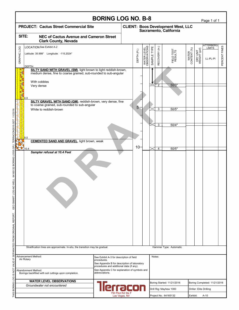
Parking AreasB-6 8’ to >10’ Medium strongB-8 9’ to >10’ WeakB-9 No fully cemented deposits encountered
1. Reference attached Exhibit C-3, Description of Rock Properties, for description of hardness.2. Weak refers to cemented soil which is rock-like and can be peeled with a pocket knife only with
difficulty and shallow indentation is made by firm blow with the point of a geological hammer.3. Medium strong refers to cemented soil which is rock-like and cannot be scraped or peeled with
a pocket knife and can be fractured with a single firm blow of a geological hammer.4. Strong refers to cemented soil which is rock-like and requires more than one blow of a
geological hammer to fracture.
Soil samples were identified by visual-manual methods using the Unified Soil ClassificationSystem (USCS). Rock-like cemented deposits were described using terminology adopted fromthe International Society for Rock Mechanics (ISRM). Descriptive classifications of soil and rockindicated on the boring logs are in accordance with the USCS and ISRM methods. Terms usedto describe soils are defined in the attached Exhibit C-1, General Notes. USCS symbols andISRM terminology are defined in attached Exhibit C-2, Unified Soil Classification System, andExhibit C-3, Description of Rock Properties.
Geotechnical Memorandum #1Cactus Street Commercial Site ■ Clark County, NevadaNovember 23, 2016 ■ Terracon Project No. 64165132
Responsive ■ Resourceful ■ Reliable 3
ClosureThis memorandum cannot be considered an independent document, as it does not contain sufficientbackground information. Thus, this memorandum is directed solely to the persons with detailedknowledge of the referenced subject site.
Our professional services have been performed using that degree of care and skill ordinarily exercisedunder similar circumstances by reputable engineering consultants practicing in this or similar localities.No other warranty, either express or implied, is made as to the professional advice included orintended in this letter.
Respectfully submitted,
Michael C. Stojanoff, PG, PEGeotechnical Department Manager
Distribution 1 PDF copy to David J. O’Donnell, [email protected]
Attachments Exhibit A-1, Site Location Map Exhibit A-2, Boring Location Plan Exhibits A-3 through A-13, Boring Logs Exhibit C-1, General Notes Exhibit C-2, Unified Soil Classification System Exhibit C-3, Description of Rock Properties
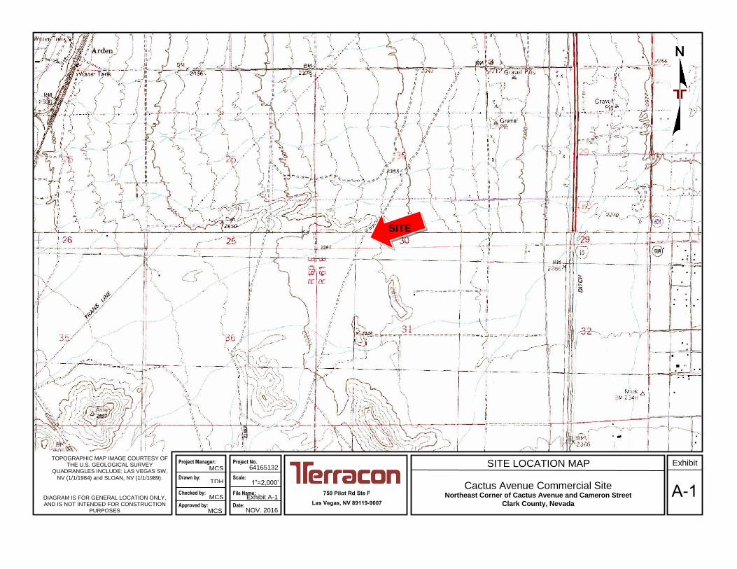
TOPOGRAPHIC MAP IMAGE COURTESY OF
THE U.S. GEOLOGICAL SURVEY QUADRANGLES INCLUDE: LAS VEGAS SW,
NV (1/1/1984) and SLOAN, NV (1/1/1989).
SITE LOCATION MAP
Cactus Avenue Commercial SiteNortheast Corner of Cactus Avenue and Cameron Street
Clark County, Nevada
750 Pilot Rd Ste F
Las Vegas, NV 89119-9007
64165132
DIAGRAM IS FOR GENERAL LOCATION ONLY, AND IS NOT INTENDED FOR CONSTRUCTION
PURPOSES
Project Manager:
Drawn by:
Checked by: Approved by:
TDH
MCS
MCS
MCS
Exhibit A-1
NOV. 2016
Project No.
File Name: Date:
A-1
Exhibit
SITE
1”=2,000’ Scale:

BORING LOCATION PLAN
Cactus Street Commercial SiteNortheast Corner of Cactus Avenue and Cameron Street
Clark County, NevadaA-2
2817 McGaw Avenue Irvine, California
PH. (949) 864-2086 FAX. (949) 261-6110
64165132
NOV. 2016
MCS
TDH
MCS
MCS
1” ~ 70’
Project Manager:
Drawn by:
Checked by:
Approved by:
Project No.
Scale:
File Name:
Date:
Exhibit
EHIBIT A-2DIAGRAM IS FOR GENERAL LOCATION
ONLY, AND IS NOT INTENDED FOR
CONSTRUCTION PURPOSES
B-1B-2
B-3
B-4
B-5
B-6
B-7B-9
B-8
B-10
B-11
LEGEND:
APPROXIMATE BORING LOCATION AND DESIGNATIONB-1

D R A
F T23-26-17
N=43
50/5"
37-50/0"
50/5"
50/6"
34-47-50/4"
1.0
5.0
7.5
10.0
13.0
15.0
18.0
20.0
21.3
SILTY GRAVEL WITH SAND (GM), light brown, medium dense, fineto coarse grained, sub-rounded to sub-angular
SILTY SAND WITH GRAVEL (SM), reddish-brown, fine to coarsegrained, sub-rounded to sub-angular
Light reddish-brown, dense
SILTY GRAVEL WITH SAND (GM), reddish-brown, very dense, fineto coarse grained, sub-rounded to sub-angular
Trace clay
CEMENTED SAND AND GRAVEL, light brown
Drilling Resistance (DR): 30 s/ft at 1,000 psi, weak to medium strong
SILTY GRAVEL WITH SAND (GM), reddish-brown, very dense, fineto coarse grained, sub-rounded to sub-angular
CEMENTED SAND AND GRAVEL, light brown, DR: 43 s/ft at 1,000psi, medium strong
DR: 20 s/ft at 1,200 psi, weak
SILTY GRAVEL WITH SAND (GM), reddish-brown, very dense, fineto coarse grained, sub-rounded to sub-angular
POORLY GRADED GRAVEL WITH SAND (GP), light reddish-brown,coarse grained, sub-rounded
SILTY GRAVEL WITH SAND (GM), light reddish-brown, fine tocoarse grained, sub-rounded to sub-angular
Sampler refusal at 21.3 Feet
6
4
2
2
2
8
GR
AP
HIC
LO
G
Hammer Type: AutomaticStratification lines are approximate. In-situ, the transition may be gradual.
TH
IS B
OR
ING
LO
G IS
NO
T V
ALI
D IF
SE
PA
RA
TE
D F
RO
M O
RIG
INA
L R
EP
OR
T.
G
EO
SM
AR
T L
OG
-NO
WE
LL 6
416
513
2 B
OR
ING
LO
GS
.GP
J T
ER
RA
CO
N20
15.G
DT
11
/23/
16
FIE
LD T
ES
TR
ES
ULT
S
DEPTH
LOCATION
Latitude: 35.9994° Longitude: -115.2032°
See Exhibit A-2
PE
RC
EN
T F
INE
S
WA
TE
RC
ON
TE
NT
(%
)
DR
Y U
NIT
WE
IGH
T (
pcf)
LL-PL-PI
ATTERBERGLIMITS
SA
MP
LE T
YP
E
WA
TE
R L
EV
EL
OB
SE
RV
AT
ION
S
DE
PT
H (
Ft.)
5
10
15
20
RE
CO
VE
RY
(In
.)
NEC of Cactus Avenue and Cameron Street Clark County, NevadaSITE:
Page 1 of 1
Advancement Method:Air Rotary
Abandonment Method:Borings backfilled with soil cuttings upon completion.
Notes:
Project No.: 64165132
Drill Rig: Mayhew 1000
Boring Started: 11/21/2016
BORING LOG NO. B-1Boos Development West, LLCCLIENT:Sacramento, California
Driller: Elite Drilling
Boring Completed: 11/21/2016
Exhibit: A-3
See Exhibit A-3 for description of fieldprocedures.See Appendix B for description of laboratoryprocedures and additional data (if any).
See Appendix C for explanation of symbols andabbreviations.
PROJECT: Cactus Street Commercial Site
750 Pilot Rd Ste FLas Vegas, NV
Groundwater not encounteredWATER LEVEL OBSERVATIONS

D R A
F T
24-50/4"
36-50/1"
39-50/0"
50/2"
50/5"
47-45-35N=80
5.0
10.0
13.0
15.0
16.0
18.0
19.5
21.5
SILTY SAND WITH GRAVEL (SM), and cobbles, light brown, mediumdense, fine to coarse grained, sub-rounded to sub-angular
With cobbles, reddish-brown
Very dense
SILTY GRAVEL WITH SAND (GM), and cobbles, reddish-brown, verydense, fine to coarse grained, sub-rounded to sub-angular
POORLY GRADED GRAVEL WITH SAND (GP), reddish-brown, verydense, coarse grained, sub-rounded
CEMENTED SAND AND GRAVEL, light brownDR: 47 s/ft at 1,200 psi, medium strong
DR: 15 s/0.5ft at 1,200 psi, weak to medium strongPOORLY GRADED GRAVEL WITH SAND (GP), reddish-brown, verydense, coarse grained, sub-roundedCEMENTED SAND AND GRAVEL, light brown, DR: 10 s/ft at 1,500psi, weak
DR: 13 s/ft at 1,200 psi
SILTY SAND WITH GRAVEL (SM), light brown, very dense, fine tocoarse grained, sub-rounded to sub-angular
SILTY GRAVEL WITH SAND (GM), reddish-brown to white, verydense, fine to coarse grained, sub-rounded to sub-angular
With cemented lenses from 21' to 21.5'
Boring Terminated at 21.5 Feet
8
3
2
0
0
GR
AP
HIC
LO
G
Hammer Type: AutomaticStratification lines are approximate. In-situ, the transition may be gradual.
TH
IS B
OR
ING
LO
G IS
NO
T V
ALI
D IF
SE
PA
RA
TE
D F
RO
M O
RIG
INA
L R
EP
OR
T.
G
EO
SM
AR
T L
OG
-NO
WE
LL 6
416
513
2 B
OR
ING
LO
GS
.GP
J T
ER
RA
CO
N20
15.G
DT
11
/23/
16
FIE
LD T
ES
TR
ES
ULT
S
DEPTH
LOCATION
Latitude: 35.9994° Longitude: -115.203°
See Exhibit A-2
PE
RC
EN
T F
INE
S
WA
TE
RC
ON
TE
NT
(%
)
DR
Y U
NIT
WE
IGH
T (
pcf)
LL-PL-PI
ATTERBERGLIMITS
SA
MP
LE T
YP
E
WA
TE
R L
EV
EL
OB
SE
RV
AT
ION
S
DE
PT
H (
Ft.)
5
10
15
20
RE
CO
VE
RY
(In
.)
NEC of Cactus Avenue and Cameron Street Clark County, NevadaSITE:
Page 1 of 1
Advancement Method:Air Rotary
Abandonment Method:Borings backfilled with soil cuttings upon completion.
Notes:
Project No.: 64165132
Drill Rig: Mayhew 1000
Boring Started: 11/21/2016
BORING LOG NO. B-2Boos Development West, LLCCLIENT:Sacramento, California
Driller: Elite Drilling
Boring Completed: 11/21/2016
Exhibit: A-4
See Exhibit A-3 for description of fieldprocedures.See Appendix B for description of laboratoryprocedures and additional data (if any).
See Appendix C for explanation of symbols andabbreviations.
PROJECT: Cactus Street Commercial Site
750 Pilot Rd Ste FLas Vegas, NV
Groundwater not encounteredWATER LEVEL OBSERVATIONS

D R A
F T12-35-50/3"
35-50/3"
50/5"
42-50/0"
25-50/2"
50/3"
2.0
4.5
5.5
12.0
15.0
20.3
SILTY SAND WITH GRAVEL (SM), light brown, medium dense, fineto coarse grained, sub-rounded to sub-angular
Reddish-brown
SILTY GRAVEL WITH SAND (GM), reddish-brown, very dense, fineto coarse grained, sub-rounded to sub-angular
POORLY GRADED GRAVEL WITH SAND (GP), reddish-brown, verydense, medium to coarse grained, sub-rounded
SILTY GRAVEL WITH SAND (GM), light reddish-brown, very dense,fine to coarse grained, sub-rounded to sub-angular
CEMENTED SAND AND GRAVEL, light brown, DR: 14 s/ft at 1,200psi, weak
DR: 17 s/ft at 1,200 psi
DR: 32 s/ft at 1,500 psi, medium strong
SILTY GRAVEL WITH SAND (GM), reddish-brown, very dense, fineto coarse grained, sub-rounded to sub-angular
Sampler refusal at 20.3 Feet
12
5
3
4
4
0
GR
AP
HIC
LO
G
Hammer Type: AutomaticStratification lines are approximate. In-situ, the transition may be gradual.
TH
IS B
OR
ING
LO
G IS
NO
T V
ALI
D IF
SE
PA
RA
TE
D F
RO
M O
RIG
INA
L R
EP
OR
T.
G
EO
SM
AR
T L
OG
-NO
WE
LL 6
416
513
2 B
OR
ING
LO
GS
.GP
J T
ER
RA
CO
N20
15.G
DT
11
/23/
16
FIE
LD T
ES
TR
ES
ULT
S
DEPTH
LOCATION
Latitude: 35.9994° Longitude: -115.2028°
See Exhibit A-2
PE
RC
EN
T F
INE
S
WA
TE
RC
ON
TE
NT
(%
)
DR
Y U
NIT
WE
IGH
T (
pcf)
LL-PL-PI
ATTERBERGLIMITS
SA
MP
LE T
YP
E
WA
TE
R L
EV
EL
OB
SE
RV
AT
ION
S
DE
PT
H (
Ft.)
5
10
15
20
RE
CO
VE
RY
(In
.)
NEC of Cactus Avenue and Cameron Street Clark County, NevadaSITE:
Page 1 of 1
Advancement Method:Air Rotary
Abandonment Method:Borings backfilled with soil cuttings upon completion.
Notes:
Project No.: 64165132
Drill Rig: Mayhew 1000
Boring Started: 11/21/2016
BORING LOG NO. B-3CLIENT: Boos Development West, LLC
Sacramento, California
Driller: Elite Drilling
Boring Completed: 11/21/2016
Exhibit: A-5
See Exhibit A-3 for description of fieldprocedures.See Appendix B for description of laboratoryprocedures and additional data (if any).
See Appendix C for explanation of symbols andabbreviations.
PROJECT: Cactus Street Commercial Site
750 Pilot Rd Ste FLas Vegas, NV
Groundwater not encounteredWATER LEVEL OBSERVATIONS

D R A
F T19-30-502"
50/3"
50/2"
50/5"
50/0"
4.0
8.0
10.0
11.0
15.0
SILTY SAND WITH GRAVEL (SM), light reddish-brown, toreddish-brown, medium dense, fine to coarse grained, sub-rounded tosub-angular
Very dense
With cemented lenses from 3' to 3.5'
SILTY GRAVEL WITH SAND (GM), light reddish-brown, very dense,fine to coarse grained, sub-rounded to sub-angular
CEMENTED SAND AND GRAVEL, light reddish-brown, DR: 22 s/ft at1,000 psi, weak
DR: 33 s/ft at 1,200 psi, medium strong
SILTY GRAVEL WITH SAND (GM), light reddish-brown, very dense,fine to coarse grained, sub-rounded to sub-angular
CEMENTED SAND AND GRAVEL, light brown, DR: 32 s/ft at 1,500psi, medium strong
DR: 38 s/ft at 1200 psi
DR: 45 s/ft at 1,500 psi
DR: 30 s/ft at 1,500 psi
Sampler refusal at 15 Feet
8
0
0
2
0
GR
AP
HIC
LO
G
Hammer Type: AutomaticStratification lines are approximate. In-situ, the transition may be gradual.
TH
IS B
OR
ING
LO
G IS
NO
T V
ALI
D IF
SE
PA
RA
TE
D F
RO
M O
RIG
INA
L R
EP
OR
T.
G
EO
SM
AR
T L
OG
-NO
WE
LL 6
416
513
2 B
OR
ING
LO
GS
.GP
J T
ER
RA
CO
N20
15.G
DT
11
/23/
16
FIE
LD T
ES
TR
ES
ULT
S
DEPTH
LOCATION
Latitude: 35.9996° Longitude: -115.2025°
See Exhibit A-2
PE
RC
EN
T F
INE
S
WA
TE
RC
ON
TE
NT
(%
)
DR
Y U
NIT
WE
IGH
T (
pcf)
LL-PL-PI
ATTERBERGLIMITS
SA
MP
LE T
YP
E
WA
TE
R L
EV
EL
OB
SE
RV
AT
ION
S
DE
PT
H (
Ft.)
5
10
15
RE
CO
VE
RY
(In
.)
NEC of Cactus Avenue and Cameron Street Clark County, NevadaSITE:
Page 1 of 1
Advancement Method:Air Rotary
Abandonment Method:Borings backfilled with soil cuttings upon completion.
Notes:
Project No.: 64165132
Drill Rig: Mayhew 1000
Boring Started: 11/21/2016
BORING LOG NO. B-4Boos Development West, LLCCLIENT:Sacramento, California
Driller: Elite Drilling
Boring Completed: 11/21/2016
Exhibit: A-6
See Exhibit A-3 for description of fieldprocedures.See Appendix B for description of laboratoryprocedures and additional data (if any).
See Appendix C for explanation of symbols andabbreviations.
PROJECT: Cactus Street Commercial Site
750 Pilot Rd Ste FLas Vegas, NV
Groundwater not encounteredWATER LEVEL OBSERVATIONS
D R A
F T50/1"
15-34-33N=67
50/4"
14-50/4"
50/3"
1.0
3.0
5.0
8.0
10.0
12.0
15.015.3
SILTY SAND WITH GRAVEL (SM), light reddish-brown, mediumdense, fine to coarse grained, sub-rounded to sub-angular
SILTY GRAVEL WITH SAND (GM), reddish-brown, very dense, fineto coarse grained, sub-rounded to sub-angular
CEMENTED SAND AND GRAVEL, light reddish-brown, weak
DR: 20 s/ft at 1,000 psi
SILTY GRAVEL WITH SAND (GM), reddish-brown, very dense, fineto coarse grained, sub-rounded to sub-angular
CEMENTED SAND AND GRAVEL, light brown, DR: 45 s/ft at 1,200psi, medium strong
DR: 29 s/ft at 1,200 psi
SILTY GRAVEL WITH SAND (GM), reddish-brown, very dense, fineto coarse grained, sub-rounded to sub-angular
CEMENTED SAND AND GRAVEL, light brown,
DR: 1m40s/ft at 1,500 psi, strong
DR: 37 s/ft at 1,200 psi, medium strong
SILTY GRAVEL WITH SAND (GM), light brown, very dense, fine tocoarse grained, sub-rounded to sub-angularSampler refusal at 15.3 Feet
0
3
2
4
0
GR
AP
HIC
LO
G
Hammer Type: AutomaticStratification lines are approximate. In-situ, the transition may be gradual.
TH
IS B
OR
ING
LO
G IS
NO
T V
ALI
D IF
SE
PA
RA
TE
D F
RO
M O
RIG
INA
L R
EP
OR
T.
G
EO
SM
AR
T L
OG
-NO
WE
LL 6
416
513
2 B
OR
ING
LO
GS
.GP
J T
ER
RA
CO
N20
15.G
DT
11
/23/
16
FIE
LD T
ES
TR
ES
ULT
S
DEPTH
LOCATION
Latitude: 35.9994° Longitude: -115.2021°
See Exhibit A-2
PE
RC
EN
T F
INE
S
WA
TE
RC
ON
TE
NT
(%
)
DR
Y U
NIT
WE
IGH
T (
pcf)
LL-PL-PI
ATTERBERGLIMITS
SA
MP
LE T
YP
E
WA
TE
R L
EV
EL
OB
SE
RV
AT
ION
S
DE
PT
H (
Ft.)
5
10
15
RE
CO
VE
RY
(In
.)
NEC of Cactus Avenue and Cameron Street Clark County, NevadaSITE:
Page 1 of 1
Advancement Method:Air Rotary
Abandonment Method:Borings backfilled with soil cuttings upon completion.
Notes:
Project No.: 64165132
Drill Rig: Mayhew 1000
Boring Started: 11/21/2016
BORING LOG NO. B-5Boos Development West, LLCCLIENT:Sacramento, California
Driller: Elite Drilling
Boring Completed: 11/21/2016
Exhibit: A-7
See Exhibit A-3 for description of fieldprocedures.See Appendix B for description of laboratoryprocedures and additional data (if any).
See Appendix C for explanation of symbols andabbreviations.
PROJECT: Cactus Street Commercial Site
750 Pilot Rd Ste FLas Vegas, NV
Groundwater not encounteredWATER LEVEL OBSERVATIONS

D R A
F T
50/3"
32-50/4"
50/2"
50/5"
1.5
4.0
5.0
8.0
10.4
SILTY SAND WITH GRAVEL (SM), light brown, medium dense, fineto coarse grained, sub-rounded to sub-angular
Reddish-brownSILTY GRAVEL WITH SAND (GM), reddish-brown, very dense, fineto coarse grained, sub-rounded to sub-angular
SILTY SAND WITH GRAVEL (SM), reddish-brown, very dense, fine tocoarse grained, sub-rounded to sub-angular
SILTY GRAVEL WITH SAND (GM), light brown to white, very dense,fine to coarse grained, sub-rounded to sub-angular
CEMENTED SAND AND GRAVEL, light brown, DR: 36 s/ft at 1,000psi, medium strong
DR: 46 s/ft at 1,200 psi
Sampler refusal at 10.4 Feet
0
8
0
2
GR
AP
HIC
LO
G
Hammer Type: AutomaticStratification lines are approximate. In-situ, the transition may be gradual.
TH
IS B
OR
ING
LO
G IS
NO
T V
ALI
D IF
SE
PA
RA
TE
D F
RO
M O
RIG
INA
L R
EP
OR
T.
G
EO
SM
AR
T L
OG
-NO
WE
LL 6
416
513
2 B
OR
ING
LO
GS
.GP
J T
ER
RA
CO
N20
15.G
DT
11
/23/
16
FIE
LD T
ES
TR
ES
ULT
S
DEPTH
LOCATION
Latitude: 35.9995° Longitude: -115.2018°
See Exhibit A-2
PE
RC
EN
T F
INE
S
WA
TE
RC
ON
TE
NT
(%
)
DR
Y U
NIT
WE
IGH
T (
pcf)
LL-PL-PI
ATTERBERGLIMITS
SA
MP
LE T
YP
E
WA
TE
R L
EV
EL
OB
SE
RV
AT
ION
S
DE
PT
H (
Ft.)
5
10
RE
CO
VE
RY
(In
.)
NEC of Cactus Avenue and Cameron Street Clark County, NevadaSITE:
Page 1 of 1
Advancement Method:Air Rotary
Abandonment Method:Borings backfilled with soil cuttings upon completion.
Notes:
Project No.: 64165132
Drill Rig: Mayhew 1000
Boring Started: 11/21/2016
BORING LOG NO. B-6Boos Development West, LLCCLIENT:Sacramento, California
Driller: Elite Drilling
Boring Completed: 11/21/2016
Exhibit: A-8
See Exhibit A-3 for description of fieldprocedures.See Appendix B for description of laboratoryprocedures and additional data (if any).
See Appendix C for explanation of symbols andabbreviations.
PROJECT: Cactus Street Commercial Site
750 Pilot Rd Ste FLas Vegas, NV
Groundwater not encounteredWATER LEVEL OBSERVATIONS

D R A
F T20-25-50/3"
27-50/2"
50/6"
50/5"
50/3"
50/3"
5.0
20.3
SILTY SAND WITH GRAVEL (SM), cobbles and boulders, light greyto light brown, medium dense, medium grained, sub-rounded tosub-angular
Very dense
Trace clay
POORLY GRADED GRAVEL WITH SILT AND SAND (GP-GM), lightbrown to light grey, very dense, medium to coarse grained, sub-angular
Fine to coarse grained
Trace clay
Sampler refusal at 20.3 Feet
4
4
3
3
2
3
GR
AP
HIC
LO
G
Hammer Type: AutomaticStratification lines are approximate. In-situ, the transition may be gradual.
TH
IS B
OR
ING
LO
G IS
NO
T V
ALI
D IF
SE
PA
RA
TE
D F
RO
M O
RIG
INA
L R
EP
OR
T.
G
EO
SM
AR
T L
OG
-NO
WE
LL 6
416
513
2 B
OR
ING
LO
GS
.GP
J T
ER
RA
CO
N20
15.G
DT
11
/23/
16
FIE
LD T
ES
TR
ES
ULT
S
DEPTH
LOCATION
Latitude: 35.999° Longitude: -115.2029°
See Exhibit A-2
PE
RC
EN
T F
INE
S
WA
TE
RC
ON
TE
NT
(%
)
DR
Y U
NIT
WE
IGH
T (
pcf)
LL-PL-PI
ATTERBERGLIMITS
SA
MP
LE T
YP
E
WA
TE
R L
EV
EL
OB
SE
RV
AT
ION
S
DE
PT
H (
Ft.)
5
10
15
20
RE
CO
VE
RY
(In
.)
NEC of Cactus Avenue and Cameron Street Clark County, NevadaSITE:
Page 1 of 1
Advancement Method:Air Rotary
Abandonment Method:Borings backfilled with soil cuttings upon completion.
Notes:
Project No.: 64165132
Drill Rig: Mayhew 1000
Boring Started: 11/21/2016
BORING LOG NO. B-7Boos Development West, LLCCLIENT:Sacramento, California
Driller: Elite Drilling
Boring Completed: 11/21/2016
Exhibit: A-9
See Exhibit A-3 for description of fieldprocedures.See Appendix B for description of laboratoryprocedures and additional data (if any).
See Appendix C for explanation of symbols andabbreviations.
PROJECT: Cactus Street Commercial Site
750 Pilot Rd Ste FLas Vegas, NV
Groundwater not encounteredWATER LEVEL OBSERVATIONS
D R A
F T
50/3"
50/5"
50/4"
50/5"
4.0
9.0
10.4
SILTY SAND WITH GRAVEL (SM), light brown to light reddish-brown,medium dense, fine to coarse grained, sub-rounded to sub-angular
With cobblesVery dense
SILTY GRAVEL WITH SAND (GM), reddish-brown, very dense, fineto coarse grained, sub-rounded to sub-angular
White to reddish-brown
CEMENTED SAND AND GRAVEL, light brown, weak
Sampler refusal at 10.4 Feet
2
3
3
4
GR
AP
HIC
LO
G
Hammer Type: AutomaticStratification lines are approximate. In-situ, the transition may be gradual.
TH
IS B
OR
ING
LO
G IS
NO
T V
ALI
D IF
SE
PA
RA
TE
D F
RO
M O
RIG
INA
L R
EP
OR
T.
G
EO
SM
AR
T L
OG
-NO
WE
LL 6
416
513
2 B
OR
ING
LO
GS
.GP
J T
ER
RA
CO
N20
15.G
DT
11
/23/
16
FIE
LD T
ES
TR
ES
ULT
S
DEPTH
LOCATION
Latitude: 35.999° Longitude: -115.2024°
See Exhibit A-2
PE
RC
EN
T F
INE
S
WA
TE
RC
ON
TE
NT
(%
)
DR
Y U
NIT
WE
IGH
T (
pcf)
LL-PL-PI
ATTERBERGLIMITS
SA
MP
LE T
YP
E
WA
TE
R L
EV
EL
OB
SE
RV
AT
ION
S
DE
PT
H (
Ft.)
5
10
RE
CO
VE
RY
(In
.)
NEC of Cactus Avenue and Cameron Street Clark County, NevadaSITE:
Page 1 of 1
Advancement Method:Air Rotary
Abandonment Method:Borings backfilled with soil cuttings upon completion.
Notes:
Project No.: 64165132
Drill Rig: Mayhew 1000
Boring Started: 11/21/2016
BORING LOG NO. B-8Boos Development West, LLCCLIENT:Sacramento, California
Driller: Elite Drilling
Boring Completed: 11/21/2016
Exhibit: A-10
See Exhibit A-3 for description of fieldprocedures.See Appendix B for description of laboratoryprocedures and additional data (if any).
See Appendix C for explanation of symbols andabbreviations.
PROJECT: Cactus Street Commercial Site
750 Pilot Rd Ste FLas Vegas, NV
Groundwater not encounteredWATER LEVEL OBSERVATIONS

D R A
F T
36-50/4"
7-7-9N=16
20-50/5"
16-34-40N=74
0.5
2.0
3.5
5.0
11.0
11.5
FILL - POORLY GRADED GRAVEL WITH SILT AND SAND(GP-GM), and cobbles, light brown, dense fine to coarse grained,sub-rounded to sub-angularPOORLY GRADED GRAVEL WITH SILT AND SAND (GP-GM),reddish-brown, very dense, fine to coarse grained, sub-rounded tosub-angularSILTY GRAVEL WITH SAND (GM), light reddish-brown, very dense,fine to coarse grained, sub-rounded to sub-angularSILTY SAND WITH GRAVEL (SM), reddish-brown, very dense, fine tocoarse grained, sub-rounded to sub-angular
POORLY GRADED GRAVEL WITH SAND (GP), reddish-brown,medium dense, fine to coarse grained, sub-rounded to sub-angular
Trace clay, very dense
Trace clay
SILTY SAND WITH GRAVEL (SM), light reddish-brown, very dense,fine to coarse grained, sub-rounded to sub-angularBoring Terminated at 11.5 Feet
9
10
6
10
GR
AP
HIC
LO
G
Hammer Type: AutomaticStratification lines are approximate. In-situ, the transition may be gradual.
TH
IS B
OR
ING
LO
G IS
NO
T V
ALI
D IF
SE
PA
RA
TE
D F
RO
M O
RIG
INA
L R
EP
OR
T.
G
EO
SM
AR
T L
OG
-NO
WE
LL 6
416
513
2 B
OR
ING
LO
GS
.GP
J T
ER
RA
CO
N20
15.G
DT
11
/23/
16
FIE
LD T
ES
TR
ES
ULT
S
DEPTH
LOCATION
Latitude: 35.9991° Longitude: -115.2018°
See Exhibit A-2
PE
RC
EN
T F
INE
S
WA
TE
RC
ON
TE
NT
(%
)
DR
Y U
NIT
WE
IGH
T (
pcf)
LL-PL-PI
ATTERBERGLIMITS
SA
MP
LE T
YP
E
WA
TE
R L
EV
EL
OB
SE
RV
AT
ION
S
DE
PT
H (
Ft.)
5
10
RE
CO
VE
RY
(In
.)
NEC of Cactus Avenue and Cameron Street Clark County, NevadaSITE:
Page 1 of 1
Advancement Method:Air Rotary
Abandonment Method:Borings backfilled with soil cuttings upon completion.
Notes:
Project No.: 64165132
Drill Rig: Mayhew 1000
Boring Started: 11/21/2016
BORING LOG NO. B-9Boos Development West, LLCCLIENT:Sacramento, California
Driller: Elite Drilling
Boring Completed: 11/21/2016
Exhibit: A-11
See Exhibit A-3 for description of fieldprocedures.See Appendix B for description of laboratoryprocedures and additional data (if any).
See Appendix C for explanation of symbols andabbreviations.
PROJECT: Cactus Street Commercial Site
750 Pilot Rd Ste FLas Vegas, NV
Groundwater not encounteredWATER LEVEL OBSERVATIONS

D R A
F T
50/5"
50/3"
20-50/3"
50/0"
50/1"
1.0
4.0
8.0
15.1
FILL - SILTY GRAVEL WITH SAND (GM), light grey, medium dense,fine to coarse grained, sub-rounded to sub-angular
SILTY SAND WITH GRAVEL (SM), reddish-brown, very dense, fine tocoarse grained, sub-rounded to sub-angular
SILTY GRAVEL WITH SAND (GM), reddish-brown, very dense, fineto coarse grained, sub-rounded to sub-angular
CEMENTED SAND AND GRAVEL, light brown, DR: 1m6s/ft at 1,500psi, strong
DR: 38 s/ft at 1,500 psi, medium strong
DR: 20 s/ft at 1,200 psi, weak
DR: 26 s/ft at 1,200 psi
DR: 26 s/ft at 1,200 psi
DR: 25 s/ft at 1,200 psi
DR: 24 s/ft at 1,200 psi
Sampler refusal at 15.1 Feet
0
3
5
0
0
GR
AP
HIC
LO
G
Hammer Type: AutomaticStratification lines are approximate. In-situ, the transition may be gradual.
TH
IS B
OR
ING
LO
G IS
NO
T V
ALI
D IF
SE
PA
RA
TE
D F
RO
M O
RIG
INA
L R
EP
OR
T.
G
EO
SM
AR
T L
OG
-NO
WE
LL 6
416
513
2 B
OR
ING
LO
GS
.GP
J T
ER
RA
CO
N20
15.G
DT
11
/23/
16
FIE
LD T
ES
TR
ES
ULT
S
DEPTH
LOCATION
Latitude: 35.999° Longitude: -115.2014°
See Exhibit A-2
PE
RC
EN
T F
INE
S
WA
TE
RC
ON
TE
NT
(%
)
DR
Y U
NIT
WE
IGH
T (
pcf)
LL-PL-PI
ATTERBERGLIMITS
SA
MP
LE T
YP
E
WA
TE
R L
EV
EL
OB
SE
RV
AT
ION
S
DE
PT
H (
Ft.)
5
10
15
RE
CO
VE
RY
(In
.)
NEC of Cactus Avenue and Cameron Street Clark County, NevadaSITE:
Page 1 of 1
Advancement Method:Air Rotary
Abandonment Method:Borings backfilled with soil cuttings upon completion.
Notes:
Project No.: 64165132
Drill Rig: Mayhew 1000
Boring Started: 11/21/2016
BORING LOG NO. B-10Boos Development West, LLCCLIENT:Sacramento, California
Driller: Elite Drilling
Boring Completed: 11/21/2016
Exhibit: A-12
See Exhibit A-3 for description of fieldprocedures.See Appendix B for description of laboratoryprocedures and additional data (if any).
See Appendix C for explanation of symbols andabbreviations.
PROJECT: Cactus Street Commercial Site
750 Pilot Rd Ste FLas Vegas, NV
Groundwater not encounteredWATER LEVEL OBSERVATIONS

D R A
F T
50/5"
27-50/0"
22-50/5"
50/3"
50/3"
1.0
2.0
6.5
7.0
9.0
10.0
12.0
15.015.3
FILL - SILTY GRAVEL WITH SAND (GM), and cobbles, light brown,medium dense, fine to coarse grained, sub-rounded to sub-angular
SILTY SAND WITH GRAVEL (SM), reddish-brown, dense, fine tocoarse grained, sub-rounded to sub-angular
SILTY GRAVEL WITH SAND (GM), light reddish-brown, very dense,fine to coarse grained, sub-rounded to sub-angular
With moderate cementation from 3.5' to 5'
Brown
CEMENTED SAND AND GRAVEL, light brown, weakSILTY GRAVEL WITH SAND (GM), light brown, very dense, fine tocoarse grained, sub-rounded to sub-angularWith cemented lenses from 7.5' to 8'
CEMENTED SAND AND GRAVEL, light brown, DR: 38 s/ft at 1,200psi, medium strong
SILTY GRAVEL WITH SAND (GM), light brown, very dense, fine tocoarse grained, sub-rounded to sub-angular
CEMENTED SAND AND GRAVEL, light brown, DR: 36 s/ft at 1,500psi, medium strong
DR: 27 s/ft at 1,500 psi
DR: 20 s/ft at 1,500 psi, weak to medium strong
SILTY GRAVEL WITH SAND (GM), brown, fine to coarse grained,sub-rounded to sub-angularSampler refusal at 15.3 Feet
2
2
9
0
2
GR
AP
HIC
LO
G
Hammer Type: AutomaticStratification lines are approximate. In-situ, the transition may be gradual.
TH
IS B
OR
ING
LO
G IS
NO
T V
ALI
D IF
SE
PA
RA
TE
D F
RO
M O
RIG
INA
L R
EP
OR
T.
G
EO
SM
AR
T L
OG
-NO
WE
LL 6
416
513
2 B
OR
ING
LO
GS
.GP
J T
ER
RA
CO
N20
15.G
DT
11
/23/
16
FIE
LD T
ES
TR
ES
ULT
S
DEPTH
LOCATION
Latitude: 35.9992° Longitude: -115.2014°
See Exhibit A-2
PE
RC
EN
T F
INE
S
WA
TE
RC
ON
TE
NT
(%
)
DR
Y U
NIT
WE
IGH
T (
pcf)
LL-PL-PI
ATTERBERGLIMITS
SA
MP
LE T
YP
E
WA
TE
R L
EV
EL
OB
SE
RV
AT
ION
S
DE
PT
H (
Ft.)
5
10
15
RE
CO
VE
RY
(In
.)
NEC of Cactus Avenue and Cameron Street Clark County, NevadaSITE:
Page 1 of 1
Advancement Method:Air Rotary
Abandonment Method:Borings backfilled with soil cuttings upon completion.
Notes:
Project No.: 64165132
Drill Rig: Mayhew 1000
Boring Started: 11/21/2016
BORING LOG NO. B-11Boos Development West, LLCCLIENT:Sacramento, California
Driller: Elite Drilling
Boring Completed: 11/21/2016
Exhibit: A-13
See Exhibit A-3 for description of fieldprocedures.See Appendix B for description of laboratoryprocedures and additional data (if any).
See Appendix C for explanation of symbols andabbreviations.
PROJECT: Cactus Street Commercial Site
750 Pilot Rd Ste FLas Vegas, NV
Groundwater not encounteredWATER LEVEL OBSERVATIONS

Exhibit: C-1
Unconfined Compressive StrengthQu, (psf)
500 to 1,000
2,000 to 4,000
4,000 to 8,000
1,000 to 2,000
less than 500
> 8,000
AugerCuttings
StandardPenetrationTest
Non-plasticLowMediumHigh
DESCRIPTION OF SYMBOLS AND ABBREVIATIONS
GENERAL NOTES
Over 12 in. (300 mm)12 in. to 3 in. (300mm to 75mm)3 in. to #4 sieve (75mm to 4.75 mm)#4 to #200 sieve (4.75mm to 0.075mmPassing #200 sieve (0.075mm)
Particle Size
< 55 - 12> 12
Percent ofDry Weight
Descriptive Term(s)of other constituents
RELATIVE PROPORTIONS OF FINES
01 - 1011 - 30
> 30
Plasticity Index
Soil classification is based on the Unified Soil Classification System. Coarse Grained Soils have more than 50% of their dryweight retained on a #200 sieve; their principal descriptors are: boulders, cobbles, gravel or sand. Fine Grained Soils haveless than 50% of their dry weight retained on a #200 sieve; they are principally described as clays if they are plastic, andsilts if they are slightly plastic or non-plastic. Major constituents may be added as modifiers and minor constituents may beadded according to the relative proportions based on grain size. In addition to gradation, coarse-grained soils are definedon the basis of their in-place relative density and fine-grained soils on the basis of their consistency.
LOCATION AND ELEVATION NOTES
Percent ofDry Weight
Major Componentof Sample
TraceWithModifier
RELATIVE PROPORTIONS OF SAND AND GRAVEL GRAIN SIZE TERMINOLOGY
TraceWithModifier
DESCRIPTIVE SOIL CLASSIFICATION
BouldersCobblesGravelSandSilt or Clay
Descriptive Term(s)of other constituents
< 1515 - 29> 30
Term
PLASTICITY DESCRIPTION
Water levels indicated on the soil boringlogs are the levels measured in theborehole at the times indicated.Groundwater level variations will occurover time. In low permeability soils,accurate determination of groundwaterlevels is not possible with short termwater level observations.
Water Level Aftera Specified Period of Time
Water Level After aSpecified Period of Time
Water InitiallyEncountered
Standard Penetration TestResistance (Blows/Ft.)
Hand Penetrometer
Torvane
Dynamic Cone Penetrometer
Photo-Ionization Detector
Organic Vapor Analyzer
Unless otherwise noted, Latitude and Longitude are approximately determined using a hand-held GPS device. The accuracyof such devices is variable. Surface elevation data annotated with +/- indicates that no actual topographical survey wasconducted to confirm the surface elevation. Instead, the surface elevation was approximately determined from topographicmaps of the area.
N
(HP)
(T)
(DCP)
(PID)
(OVA)
FIE
LD
TE
ST
S
WA
TE
R L
EV
EL
SA
MP
LIN
GS
TR
EN
GT
H T
ER
MS Standard Penetration or
N-ValueBlows/Ft.
Descriptive Term(Consistency)
Descriptive Term(Density)
CONSISTENCY OF FINE-GRAINED SOILS
(50% or more passing the No. 200 sieve.)Consistency determined by laboratory shear strength testing, field
visual-manual procedures or standard penetration resistance
Standard Penetration orN-Value
Blows/Ft.
(More than 50% retained on No. 200 sieve.)Density determined by Standard Penetration Resistance
RELATIVE DENSITY OF COARSE-GRAINED SOILS
Hard > 30
> 50 15 - 30Very Stiff
Stiff
Medium Stiff
Very Soft 0 - 1
Medium Dense
SoftLoose
Very Dense
8 - 1530 - 50Dense
4 - 810 - 29
2 - 44 - 9
Very Loose 0 - 3

Exhibit C-2
UNIFIED SOIL CLASSIFICATION SYSTEM
Criteria for Assigning Group Symbols and Group Names Using Laboratory Tests A Soil Classification
Group Symbol
Group Name B
Coarse Grained Soils: More than 50% retained on No. 200 sieve
Gravels: More than 50% of coarse fraction retained on No. 4 sieve
Clean Gravels: Less than 5% fines C
Cu 4 and 1 Cc 3 E GW Well-graded gravel F
Cu 4 and/or 1 Cc 3 E GP Poorly graded gravel F
Gravels with Fines: More than 12% fines C
Fines classify as ML or MH GM Silty gravel F,G,H
Fines classify as CL or CH GC Clayey gravel F,G,H
Sands: 50% or more of coarse fraction passes No. 4 sieve
Clean Sands: Less than 5% fines D
Cu 6 and 1 Cc 3 E SW Well-graded sand I
Cu 6 and/or 1 Cc 3 E SP Poorly graded sand I
Sands with Fines: More than 12% fines D
Fines classify as ML or MH SM Silty sand G,H,I
Fines classify as CL or CH SC Clayey sand G,H,I
Fine-Grained Soils: 50% or more passes the No. 200 sieve
Silts and Clays: Liquid limit less than 50
Inorganic: PI 7 and plots on or above “A” line J CL Lean clay K,L,M
PI 4 or plots below “A” line J ML Silt K,L,M
Organic: Liquid limit - oven dried
0.75 OL Organic clay K,L,M,N
Liquid limit - not dried Organic silt K,L,M,O
Silts and Clays: Liquid limit 50 or more
Inorganic: PI plots on or above “A” line CH Fat clay K,L,M
PI plots below “A” line MH Elastic Silt K,L,M
Organic: Liquid limit - oven dried
0.75 OH Organic clay K,L,M,P
Liquid limit - not dried Organic silt K,L,M,Q
Highly organic soils: Primarily organic matter, dark in color, and organic odor PT Peat
A Based on the material passing the 3-inch (75-mm) sieve B If field sample contained cobbles or boulders, or both, add “with cobbles
or boulders, or both” to group name. C Gravels with 5 to 12% fines require dual symbols: GW-GM well-graded
gravel with silt, GW-GC well-graded gravel with clay, GP-GM poorly graded gravel with silt, GP-GC poorly graded gravel with clay.
D Sands with 5 to 12% fines require dual symbols: SW-SM well-graded sand with silt, SW-SC well-graded sand with clay, SP-SM poorly graded sand with silt, SP-SC poorly graded sand with clay
E Cu = D60/D10 Cc =
6010
2
30
DxD
)(D
F If soil contains 15% sand, add “with sand” to group name. G If fines classify as CL-ML, use dual symbol GC-GM, or SC-SM.
H If fines are organic, add “with organic fines” to group name. I If soil contains 15% gravel, add “with gravel” to group name. J If Atterberg limits plot in shaded area, soil is a CL-ML, silty clay. K If soil contains 15 to 29% plus No. 200, add “with sand” or “with gravel,”
whichever is predominant. L If soil contains 30% plus No. 200 predominantly sand, add “sandy” to
group name. M If soil contains 30% plus No. 200, predominantly gravel, add
“gravelly” to group name. N PI 4 and plots on or above “A” line. O PI 4 or plots below “A” line. P PI plots on or above “A” line. Q PI plots below “A” line.

Exhibit C-3
DESCRIPTION OF ROCK PROPERTIES
WEATHERINGTerm Description Unweathered No visible sign of rock material weathering, perhaps slight discoloration on major discontinuity surfaces. Slightly weathered
Discoloration indicates weathering of rock material and discontinuity surfaces. All the rock material may be discolored by weathering and may be somewhat weaker externally than in its fresh condition.
Moderately weathered
Less than half of the rock material is decomposed and/or disintegrated to a soil. Fresh or discolored rock is present either as a continuous framework or as corestones.
Highly weathered
More than half of the rock material is decomposed and/or disintegrated to a soil. Fresh or discolored rock is present either as a discontinuous framework or as corestones.
Completely weathered
All rock material is decomposed and/or disintegrated to soil. The original mass structure is still largely intact.
Residual soil All rock material is converted to soil. The mass structure and material fabric are destroyed. There is a large change in volume, but the soil has not been significantly transported.
STRENGTH OR HARDNESS
Description Field Identification Uniaxial Compressive Strength, PSI (MPa)
Extremely weak Indented by thumbnail 40-150 (0.3-1)
Very weak Crumbles under firm blows with point of geological hammer, can be peeled by a pocket knife
150-700 (1-5)
Weak rock Can be peeled by a pocket knife with difficulty, shallow indentations made by firm blow with point of geological hammer
700-4,000 (5-30)
Medium strong Cannot be scraped or peeled with a pocket knife, specimen can be fractured with single firm blow of geological hammer
4,000-7,000 (30-50)
Strong rock Specimen requires more than one blow of geological hammer to fracture it
7,000-15,000 (50-100)
Very strong Specimen requires many blows of geological hammer to fracture it 15,000-36,000 (100-250) Extremely strong Specimen can only be chipped with geological hammer >36,000 (>250)
DISCONTINUITY DESCRIPTION
Fracture Spacing (Joints, Faults, Other Fractures) Bedding Spacing (May Include Foliation or Banding)
Description Spacing Description Spacing
Extremely close < ¾ in (<19 mm) Laminated < ½ in (<12 mm)
Very close ¾ in – 2-1/2 in (19 - 60 mm) Very thin ½ in – 2 in (12 – 50 mm)
Close 2-1/2 in – 8 in (60 – 200 mm) Thin 2 in – 1 ft (50 – 300 mm)
Moderate 8 in – 2 ft (200 – 600 mm) Medium 1 ft – 3 ft (300 – 900 mm)
Wide 2 ft – 6 ft (600 mm – 2.0 m) Thick 3 ft – 10 ft (900 mm – 3 m)
Very Wide 6 ft – 20 ft (2.0 – 6 m) Massive > 10 ft (3 m) Discontinuity Orientation (Angle): Measure the angle of discontinuity relative to a plane perpendicular to the longitudinal axis of the core. (For most cases, the core axis is vertical; therefore, the plane perpendicular to the core axis is horizontal.) For example, a horizontal bedding plane would have a 0 degree angle.
ROCK QUALITY DESIGNATION (RQD*) Description RQD Value (%) Very Poor 0 - 25
Poor 25 – 50 Fair 50 – 75
Good 75 – 90 Excellent 90 - 100
*The combined length of all sound and intact core segments equal to or greater than 4 inches in length, expressed as a percentage of the total core run length.
Reference: U.S. Department of Transportation, Federal Highway Administration, Publication No FHWA-NHI-10-034, December 2009
Technical Manual for Design and Construction of Road Tunnels – Civil Elements