Geographic-Aware Augmented Reality for VGI
9
Geographic-Aware Augmented Reality for VGI Paolo Fogliaroni a, b* , Bartosz Mazurkiewicz a , Markus Kattenbeck a , Ioannis Giannopoulos a a Research Group Geoinformation, Vienna University of Technology, Austria, [firstname.lastname]@geo.tuwien.ac.at b ESRI R&D Center Vienna, Austria, [email protected] * Corresponding Author Abstract: Volunteered Geographic Information (VGI) has been a constantly growing field over the last decade, but the utilised technologies (i.e., mobile phones) are not able to exploit the full potential concerning effort and accur- acy of registering geographic data. This paper introduces the GeoAR Glasses, a novel technology enabling the use of Geographic-Aware Augmented Reality for Mobile Geographic Information Systems (Mobile GIS) and Location-Based Services (LBS). The potentials of the GeoAR Glasses with respect to current mobile mapping applications is shown by means of an in-situ study (N=42) comparing two different modes of collecting VGI data. For the comparison we take into account the accuracy of the mapped data points and the time needed to complete the mapping. The results show that the GeoAR Glasses outperform the mobile application concerning both positional accuracy and completion time. Keywords: volunteered geographic information, augmented reality, geoAR, in-situ study 1. Introduction Recently, several studies have indicated that volunteered geographic information (VGI, Goodchild (2007) is of reas- onable accuracy (Fan et al., 2014, Neis et al., 2012, Hak- lay, 2010). Those studies, however, do not analyse the cor- relation between accuracy level and the approach used to contribute the data. In particular, the positional accuracy of the contributed features might be poor in those cases in which the mapping is done in-situ using a mobile GIS ap- plication and, at the same time, the features to be mapped are located in an area which is not physically accessible to the mapper. The mapping of natural features in urban flowerbeds is one substantial example for such a scenario in which objects (i.e. trees, bushes, manhole covers, lamp- posts etc.) may not be reachable physically because it is prohibited to enter the area they are located in—e.g., be- cause entering the flowerbed might damage vegetation. In these situations, using smartphone applications, may lead to inaccurate results because users are required to estimate the position of objects in relation to (i) their own location, (ii) the area in which the objects are located in and, pos- sibly, (iii) other features than the objects of interest which might also be located in the same area. In this paper we introduce the Geographic-aware Augmen- ted Reality Glasses (GeoAR Glasses) which are suitable to overcome these issues. The GeoAR Glasses are an AR headset technology designed to work in outdoor environ- ments. They allow for both, handling geographic data (i.e., providing a holographic representation of geographically referenced data–see Section 3.1) and supporting user inter- action with spatial entities (i.e., enabling the user to virtu- ally interact with physical entities–see Section 3.2). To assess the potential of this novel technology, we set up a between-subjects user study comparing the well-known smartphone mapping approach (condition smartphone) to our novel GeoAR Glasses mapping approach (condition GeoAR Glasses). Participants were asked to map a fixed configuration of ten street cones placed in a delimited area that they were not allowed to enter, thereby enforcing map- ping from a distance. We compared two parameters: The accuracy of mapped locations and the time needed to com- plete the task. The results show that the GeoAR Glasses outperform the smartphone mapping approach concerning both positional accuracy and completion time. While, in this work, we present the novel GeoAR Glasses in a context of point data collection, it has to be noted that the techno- logy lends itself to many other applications. For example, it could be used as a mobile GIS by surveying companies, or be employed in a tourism context to display geograph- ically referenced information about historical monuments. 2. Related work 2.1 VGI Quality Spatial information collected by volunteers is commonly referred to as Volunteered Geographic Information (VGI) and can come in different forms, such as text, images, maps (Goodchild, 2007). OpenStreetMap (OSM) 1 is probably the most popular and most important example of VGI source, with more than 5 million contributors as of mid-2019. Other examples include Wikimapia 2 and Flickr 3 , among others. Generally speaking, there are different quality measures for geographic data: positional, geometric and semantic accuracy, completeness and reputation (Fogliaroni et al., 2018), among others (Senaratne et al., 2017). As the tech- nology presented in this work deals with positional accur- acy we will focus on this quality measure. In order to as- sess the positional accuracy of OSM data, several studies compared it to official datasets. In (Haklay, 2010), OSM data is compared against Ordnance Survey data. The au- thors conclude that OSM can be of reasonable accuracy as 1 https://www.openstreetmap.org 2 https://wikimapia.org/ 3 https://www.flickr.com/ Advances in Cartography and GIScience of the International Cartographic Association, 2, 2019. 15th International Conference on Location Based Services, 11–13 November 2019, Vienna, Austria. This contribution underwent double-blind peer review based on the full paper | https://doi.org/10.5194/ica-adv-2-3-2019 | © Authors 2019. CC BY 4.0 License
Transcript of Geographic-Aware Augmented Reality for VGI

Geographic-Aware Augmented Reality for VGI
Paolo Fogliaronia, b∗, Bartosz Mazurkiewicza, Markus Kattenbecka, Ioannis Giannopoulosa
a Research Group Geoinformation, Vienna University of Technology, Austria, [firstname.lastname]@geo.tuwien.ac.atb ESRI R&D Center Vienna, Austria, [email protected]
* Corresponding Author
Abstract: Volunteered Geographic Information (VGI) has been a constantly growing field over the last decade, butthe utilised technologies (i.e., mobile phones) are not able to exploit the full potential concerning effort and accur-acy of registering geographic data. This paper introduces the GeoAR Glasses, a novel technology enabling the use ofGeographic-Aware Augmented Reality for Mobile Geographic Information Systems (Mobile GIS) and Location-BasedServices (LBS). The potentials of the GeoAR Glasses with respect to current mobile mapping applications is shown bymeans of an in-situ study (N=42) comparing two different modes of collecting VGI data. For the comparison we take intoaccount the accuracy of the mapped data points and the time needed to complete the mapping. The results show that theGeoAR Glasses outperform the mobile application concerning both positional accuracy and completion time.
Keywords: volunteered geographic information, augmented reality, geoAR, in-situ study
1. Introduction
Recently, several studies have indicated that volunteeredgeographic information (VGI, Goodchild (2007) is of reas-onable accuracy (Fan et al., 2014, Neis et al., 2012, Hak-lay, 2010). Those studies, however, do not analyse the cor-relation between accuracy level and the approach used tocontribute the data. In particular, the positional accuracyof the contributed features might be poor in those cases inwhich the mapping is done in-situ using a mobile GIS ap-plication and, at the same time, the features to be mappedare located in an area which is not physically accessibleto the mapper. The mapping of natural features in urbanflowerbeds is one substantial example for such a scenarioin which objects (i.e. trees, bushes, manhole covers, lamp-posts etc.) may not be reachable physically because it isprohibited to enter the area they are located in—e.g., be-cause entering the flowerbed might damage vegetation. Inthese situations, using smartphone applications, may leadto inaccurate results because users are required to estimatethe position of objects in relation to (i) their own location,(ii) the area in which the objects are located in and, pos-sibly, (iii) other features than the objects of interest whichmight also be located in the same area.
In this paper we introduce the Geographic-aware Augmen-ted Reality Glasses (GeoAR Glasses) which are suitableto overcome these issues. The GeoAR Glasses are an ARheadset technology designed to work in outdoor environ-ments. They allow for both, handling geographic data (i.e.,providing a holographic representation of geographicallyreferenced data–see Section 3.1) and supporting user inter-action with spatial entities (i.e., enabling the user to virtu-ally interact with physical entities–see Section 3.2).
To assess the potential of this novel technology, we set upa between-subjects user study comparing the well-knownsmartphone mapping approach (condition smartphone) toour novel GeoAR Glasses mapping approach (conditionGeoAR Glasses). Participants were asked to map a fixed
configuration of ten street cones placed in a delimited areathat they were not allowed to enter, thereby enforcing map-ping from a distance. We compared two parameters: Theaccuracy of mapped locations and the time needed to com-plete the task. The results show that the GeoAR Glassesoutperform the smartphone mapping approach concerningboth positional accuracy and completion time. While, inthis work, we present the novel GeoAR Glasses in a contextof point data collection, it has to be noted that the techno-logy lends itself to many other applications. For example,it could be used as a mobile GIS by surveying companies,or be employed in a tourism context to display geograph-ically referenced information about historical monuments.
2. Related work
2.1 VGI Quality
Spatial information collected by volunteers is commonlyreferred to as Volunteered Geographic Information (VGI)and can come in different forms, such as text, images, maps(Goodchild, 2007). OpenStreetMap (OSM)1 is probablythe most popular and most important example of VGI source,with more than 5 million contributors as of mid-2019. Otherexamples include Wikimapia2 and Flickr3, among others.
Generally speaking, there are different quality measuresfor geographic data: positional, geometric and semanticaccuracy, completeness and reputation (Fogliaroni et al.,2018), among others (Senaratne et al., 2017). As the tech-nology presented in this work deals with positional accur-acy we will focus on this quality measure. In order to as-sess the positional accuracy of OSM data, several studiescompared it to official datasets. In (Haklay, 2010), OSMdata is compared against Ordnance Survey data. The au-thors conclude that OSM can be of reasonable accuracy as
1https://www.openstreetmap.org2https://wikimapia.org/3https://www.flickr.com/
Advances in Cartography and GIScience of the International Cartographic Association, 2, 2019. 15th International Conference on Location Based Services, 11–13 November 2019, Vienna, Austria. This contribution underwent double-blind peer review based on the full paper | https://doi.org/10.5194/ica-adv-2-3-2019 | © Authors 2019. CC BY 4.0 License

2 of 9
(a) (b) (c)
Figure 1. The GeoAR technology: (a) The GeoAR Glasses combine a Microsoft HoloLens and a PPM 10XX GNSSreceiver . The front glass of the HoloLens and its environmental cameras have been covered with a light-filtering film tocounter the excessive brightness of sunlight; (b) Field view during an experiment; every mapped point feature is markedby a blue sphere; (c) a participant wearing the GeoAR Glasses.
they found an average positional error of 6 metres. Simil-arly, OSM building polygons have been compared to offi-cial vector data of Milan Municipality, Italy (Brovelli et al.,2016). The analysis shows a systematic translation of 0.4metres and a mean positional error of 0.8 metres. Thesetwo examples and the work in (Ribeiro and Fonte, 2015)provide evidence that the data quality of OSM varies (e.g.urban vs rural areas). While these studies, among others,indicate positional accuracy issues in OSM data, they donot take into account whether the order of magnitude inpositional error is related to the used mapping technique.2.2 OSM Data Collection MethodsThe most common ways of contributing new data to OSMare armchair mapping, bulk imports, and in-situ surveys(Mooney and Minghini, 2017). Armchair mapping refersmainly, but is not limited to, digitising geographic featuresbased on satellite imagery of areas that are frequently notknown to the contributing person (OpenStreetMap, 2019b).This approach comes at the cost of neglecting knowledgeabout the local environment; this knowledge, however, maybe highly important to interpret a feature correctly. Addi-tionally, armchair mapping may yield incomplete or inac-curate results in those cases where some features are fullyor partially covered by others, e.g. buildings or trees cov-ering features at the ground level.Bulk imports refer to cases where proprietary data are re-leased for use in OSM and huge sets of features are up-loaded in a single batch into the database. One notableexample resulting in a large increase of data available inOSM is the 2008 bulk import of the US Census TIGER/Line(Zielstra et al., 2013).In-situ surveys which can come in different shapes, e.g.on the spot editing, collecting points and tracks via GlobalNavigation Satellite System (GNSS) devices, photo or videomapping, and field papers (OpenStreetMap, 2018). Post-processing is required for all but the first of these options.Several smartphone applications enable direct editing ofOSM (OpenStreetMap, 2019a) data. Users can either maptheir own position or place entities anywhere else on themap using a typical point-and-click interaction.2.3 Outdoor Augmented RealityEarly approaches to outdoor AR rely on GNSS for localisa-tion and inertial and magnetic sensors for orientation and
heading. Examples include the Touring Machine (Feiner etal., 1997), the mobile augmented reality system (MARS)presented in (Hollerer et al., 1999), and the work presen-ted by Azuma et al. (Azuma et al., 1999) and Baillot andcolleagues (Baillot et al., 2001). The results of these earlyapproaches were promising but outlined two main prob-lems: First, using magnetic sensors yields unreliable res-ults due to electromagnetic distortions; second, the updatefrequency (typically 1Hz) of the GNSS receiver is too lowto offer a seamless user experience.
Subsequent work has focused on overcoming both issues.The most promising approaches rely on vision-based loc-alisation. For example, a model-based hybrid system waspresented which used a 3D model of the environment toimprove the tracking of edges based on camera images(Reitmayr and Drummond, 2006). A second example isthe work done by Li and colleagues who used AR to visu-alise underground infrastructure (Li et al., 2018) using aGoogle Tango Phab 2 (Marder-Eppstein, 2016). This sys-tem makes heavy use of area description files (ADF) of theenvironment that have to be collected in a preliminary off-line step in which the Tango device is used to scan the en-vironment. In the online phase the currently scanned envir-onment is compared against the corresponding ADF in thedatabase to compute a seven-parameter coordinate trans-formation to map the geographic coordinates of the under-ground infrastructure onto the world space of the Tangodevice. The virtual objects representing the undergroundinfrastructure are created in the Tango coordinate referencesystem and the localisation capabilities of the Tango deviceare leveraged to keep the virtual objects registered to thereal environment as the user moves. Our GeoAR Glassesapplies a similar approach but does not require to prelim-inary scan the location of interest.
3. Technology and Methodology
3.1 GeoAR Glasses Technology
Figure 1a shows our GeoAR Glasses, a Geographic-AwareAugmented Reality headset. The main hardware compon-ents are a Microsoft HoloLens (v1) and a PPM 10XX GNSSreceiver. The HoloLens is a mobile AR headset which hasbeen designed for indoor environments. It allows for posi-tioning virtual objects in a local Cartesian reference system
Advances in Cartography and GIScience of the International Cartographic Association, 2, 2019. 15th International Conference on Location Based Services, 11–13 November 2019, Vienna, Austria. This contribution underwent double-blind peer review based on the full paper | https://doi.org/10.5194/ica-adv-2-3-2019 | © Authors 2019. CC BY 4.0 License

3 of 9
whose origin is located at the physical position occupied bythe HoloLens at start-up. Its local coordinate reference sys-tem (CRS) is left-handed with x-, y-, and z-axis pointingto the right, upwards, and forward, respectively. The PPM10XX GNSS receiver is equipped with a GPS+GLONASSL1/L2 Helix antenna and mounts a Trimble MB-Two board.With optimal satellite coverage, this device provides a po-sitional accuracy of 1.5m without correction data, 0.8mwith EGNOS augmentation, and 0.008m+ 1ppm with RTKcorrection data and resolved ambiguities.
We enabled a Microsoft HoloLens to work in geographicspace by applying techniques derived from the fields ofland surveying and adjustment computations. During ashort calibration phase, which is done by the experimenter,we compute a seven-parameter similarity transformation(Ghilani, 2017, Section 18.7) by collecting four calibra-tion points (aka, ”pass-points”). The points are collec-ted in both the geographic and the local reference system.For the former we use the RTK-corrected data providedby the PPM 10XX GNSS receiver, with correction data ob-tained by the EPOSA4 virtual RTK web service; the latterare provided by the HoloLens. The calibration points areused to compute the transformation parameters directly onthe HoloLens according to the formulae given by Ghilani(Ghilani, 2017, Section 18.7). The computed parametersallow for spatial transformations from geographic spaceinto local space and vice-versa.
The GeoAR Glasses positional accuracy was assessed dur-ing several test phases during which we also carried out ac-curacy measurements. In optimal conditions for the GNSSantenna, we obtained a mean 2D positional accuracy (i.e.,the distance on the ground between an actual point and thecorresponding geographic coordinates) ranging between 1cmand 5cm within the calibration area — i.e., the area delim-ited by the locations of the pass-points. It is important tonote that — since the HoloLens positioning system relieson a vision-based technique — the positional accuracy ofthe calibration points in the local reference system also de-pends on the structure of the environment. The larger thenumber of visually distinguishable features (e.g., an urbanenvironment featuring buildings and other visually distin-guishable landmarks) the environment offers, the more ac-curate the coordinates of the pass-points in the local ref-erence system are and, accordingly, the transformation. Inthese cases, we reach the best accuracy (1cm). If the envir-onment, however, offers only a small number of referencefeatures (e.g., a green area where it is difficult to distin-guish between two similar trees), we obtain an accuracy ofapprox. 5cm.
Outside the calibration area, the accuracy deteriorates lin-early at a rate of approx. 5cm to 7cm for every 5m dis-tance from the boundary of the calibration area. The ac-curacy deterioration rate depends on the size of the calib-ration area, i.e., the larger the area, the smaller the deterior-ation. We performed tests with square-shaped calibrationareas with side lengths of 5m and 10m and performed po-sitional accuracy measurements up to a distance of 50mfrom their centroids. A constant accuracy outside the cal-ibration area can be maintained by applying a continuouscalibration process—i.e. by collecting further calibration
4http://www.eposa.at
points as the user walks away from the initial calibrationarea.
In case the calibration area is not left or the accuracy out-side the calibration area is not crucial for the application athand, the GNSS antenna is no longer needed once the cal-ibration phase is finished. This is a major advantage of theGeoAR Glasses: They can be used even in areas which donot feature an optimal GNSS satellite coverage.
3.2 GeoAR Glasses Data Collection Approach
The HoloLens features a cursor that is always located atthe centre of the user’s field of view. If the line of sightthat runs through the cursor does not intersect any object,the cursor floats in front of the user at a fixed distance.Otherwise, the cursor sticks to an object’s surface, i.e., itis placed at the intersection between the surface and theray running through the centre of the user’s field of view(see Figure 2a). In our experiment, we used the HoloLensto generate a mesh surface of the experimental area that isneeded to let the cursor hit the terrain. Note that, altern-atively, the mesh can be generated from available digitalterrain models. Taken together, collecting a single pointfeature required to, first, gazing at the point to be mappedand, then, perform an air-tap gesture, as shown in the pic-ture sequence in Figure 2.
(a) (b) (c)
Figure 2. Mapping a point using the GeoAR Glasses con-sists of (a) gazing at the point to be mapped and (b, c)perform an air-tap gesture. A cyan sphere of 5cm radiusappears at the tapped location (c), providing visual feed-back of the mapped point.
Once the air-tap gesture was performed, a cyan sphere ofradius 5cm appeared at the tapped location (see Figure 2c)with a board attached on top of it which displays the num-ber of the mapped point (see Figure 1b). The number wasincremented automatically by the application and the boardwas set 2m above the sphere in order to avoid visual clut-ter. Editing the position of a sphere was possible by settingthe cursor on the sphere surface and performing an air-tapgesture. In doing so, the sphere enters the edit-mode dur-ing which it follows the user’s gaze (i.e., the cursor) untilthe air-tap gesture is performed again to confirm the newposition.
3.3 Smartphone Data Collection Approach
All control group participants performed the experimentwith a OnePlus 5T smartphone (Android 8.1.0) using theapplication OSMAND (V3.3.8), a smartphone applicationwhich implements the established mobile mapping UI. Thisparticular mapping application was chosen for three reas-ons: First, it comes with export mechanisms for newly ad-ded features; second, it does not upload any changes auto-matically to OSM; third, its user interface is easy to under-stand and, hence, suitable for beginners.
Advances in Cartography and GIScience of the International Cartographic Association, 2, 2019. 15th International Conference on Location Based Services, 11–13 November 2019, Vienna, Austria. This contribution underwent double-blind peer review based on the full paper | https://doi.org/10.5194/ica-adv-2-3-2019 | © Authors 2019. CC BY 4.0 License

4 of 9
(a) (b)
Figure 3. The interface of OSMAND (V3.3.8). (a) Cre-ation of feature 3. (b) Give the feature a name.
As experiments were conducted in German (see section3.4) the application was used with its German interface(see Figure 3). OSMAND (V3.3.8) provides a classicalgraphical feedback (blue dot) about position and orienta-tion of the smartphone and participants could pan, zoomand rotate the displayed map. In order to collect a feature,participants were required to, first, perform a long-presson the map at the corresponding location they wanted tocreate the feature at. They, then, had to click the buttonAktionen (Actions), then click POI erstellen (create POI),provide the feature number as name and then confirm bypressing enter twice, in which the second press confirmsthe pop-up window regarding the blank POI type. A cir-cular marker will then appear on the map at the specifiedlocation. In order to edit a previously set marker, users hadto tap on the marker to be edited, press Aktionen (Actions)and then select Position der Markierung Andern (Changethe position of the marker). From this point in time on, themap can be dragged to place the point at a new position.The new location needs then be confirmed by the user byclicking the confirm button.
3.4 Experimental SetupIn order to compare our GeoAR approach to an establishedway of mapping on smartphones, we asked participants tomap ten traffic cones as fast and as accurate as possible inascending order. The participants were instructed to mapthe centre of the cone.
Figure 4 shows the spatial layout of the experimental setupused across both experiment conditions; Table 1 reports re-lative distances between the cones for reproducibility reas-ons. The order of traffic cones was randomly chosen butfixed to the same sequence for all participants across con-ditions. The overall experimental area was 10m× 10m insize, whereas the mapping area (represented by the dashed-line polygon in Figure 4) covered 9.1m × 9.1m. Parti-cipants were allowed to move freely in the area betweenthe drawn-through and the dashed line, which was .9 metreswide, but were neither allowed to enter the area insidethe dashed polygon nor to cross the overall experimentalarea. The geographic locations of the points were ran-domly chosen as well as the fixed starting point for all
Figure 4. A schematic representation of the spatial layoutof the experimental setup. Numbers indicate the random-ized order in which all participants were required to maptraffic cones. The starting position is denoted by an X. Par-ticipants were neither allowed to enter the area inside thedashed polygon nor to cross the overall experimental area(the outer polygon), which was 10m× 10m in size.
trials was (shown as an X in Figure 4). Neither a two-sided Clarke-Evans test (R = 1.0335, p = .8392) nor atwo-sided Conditional Monte Carlo test of complete spa-tial randomness based on quadrat counts (χ2 = 25.303,p = .481) yielded a significant result for cone positions,i.e., the assumption of spatial randomness of these loca-tions could not be rejected. The cones were placed on grass
1 2 3 4 5 6 7 8 9 10
1 0 5.38 2.47 3.32 3.79 4.62 6.09 1.05 6.02 1.672 0 2.94 5.59 7.05 6.07 6.22 5.81 .93 5.843 0 3.36 4.61 4.33 5.25 3.07 3.54 3.304 0 1.50 1.29 2.88 4.37 5.73 4.985 0 1.97 3.60 4.75 7.23 5.416 0 1.69 5.66 6.01 6.277 0 7.13 5.91 7.698 0 6.54 .679 0 6.63
10 0
Table 1. The distance matrix of cone positions; distancesare given in metres.
in order to ensure high visibility and a red-white colouredstick was placed in the centre of each cone to ensure thattheir location was fixed and to give participants a furtherhint on the location of the actual cone centre on the ground(see Figure 5 for a picture of the experimental area). Thereason for using traffic cones was twofold. First, comparedto, e.g., real green features such as trees, confounding ef-fects with respect to height and diameter can be controlledas all cones were of equal size and shape. Second, theground-truth geographic location can be measured using aPPM 10XX GNSS receiver external antenna (no tree cover-age), which was inevitable because of the need to recreatethe test setup on every of the ND = 8 days of data col-lection. This means, first, we used the PPM 10XX GNSSreceiver to position the cones as close as possible at theirrandomly chosen location. Using this method we were ableto replicate the setup of locations within a range of 6 cmin easting direction and 9 cm in northing direction acrossdays (the slight positional variation across different days isdue to inclination of the sticks used to keep the cones inplace) . Second, to avoid confounding effects from pos-
Advances in Cartography and GIScience of the International Cartographic Association, 2, 2019. 15th International Conference on Location Based Services, 11–13 November 2019, Vienna, Austria. This contribution underwent double-blind peer review based on the full paper | https://doi.org/10.5194/ica-adv-2-3-2019 | © Authors 2019. CC BY 4.0 License

5 of 9
sibly occurring differences in locations of traffic cones, webased all calculations of differences between mapped andground truth positions on these daily measurements5. Inaddition to that, for each day, we performed a calibrationaround the experiment area (see Section 3.1) by collectingthe calibration points at fixed spots. Using the best GNSSaccuracy level, we ensured a transformation accuracy ofless than 5cm by collecting the calibration points. Occa-sionally, however, the HoloLens would shut down duringthe day due to overheating because of the environmentaltemperature. In any such cases, we restarted the applica-tion and repeated the calibration procedure.
Figure 5. An image of the experimental area.
We employed a between-subjects design using two differ-ent conditions: In condition GeoAR Glasses, participantswere asked to map the position of ten traffic cones as fastand as accurate as possible using the GeoAR Glasses; incondition smartphone, participants were assigned the sametask using the OSMAND (V3.3.8) application. Participantsassigned to the smartphone condition had to do one addi-tional step to complete the same task: assign each mappedcone a number (see Figure 3). As we expected to find alarge effect we calculatedN = 42 as a suitable sample sizefor comparing independent groups, based on the signific-ance level α = .05, power 1 − β = .8, ratio of group sizesN2/N1 = 1 and effect size d = .8 (Cohen, 1988) using thetool GPower (Faul et al., 2007). Participants were acquiredin-situ, i.e. next to the experimental area which was loc-ated in a park. They were not reimbursed immediately forparticipation but could take part in a lottery using a Sam-sung Galaxy Tab 10.1 as a possible price. A prerequis-ite for participation was that participants did not contrib-ute to OpenStreetMap on a regular basis. All experimentswere conducted in German language. We ran experimentssuccessively, i.e. we completed all smartphone trials first,and, once finished, continued to run GeoAR Glasses ex-periments. Across conditions participants were subject tothe same procedure: They, first, gave their informed con-sent to participate in the experiment. Next, they filled in ademographic data survey also comprising questions abouttheir prior engagement in mapping tasks, usage of smart-phones and their experience with augmented and/or vir-tual reality devices. The task description was then givento participants in writing. The task description explicitlyasked participants to map the geographic position of thecorresponding centre for each traffic cone as accurate and
5Due to technical reasons, ground truth measurements were not recor-ded on two days; we used median imputation to account for these missingdatasets.
as fast as they could. After having read the task descrip-tion, participants were subjected to a short training phasefor the mapping task in order to familiarise them with thetask and their assigned condition. The training area waslocated next to the experimental area.
All GeoAR Glasses participants were taught about the air-tap gesture and the functionalities of the application andhelped to correctly wear the glasses, making sure that thecursor was visible. Throughout the training phase, the par-ticipant was asked to map 3 manhole covers next to the ex-periment area using the method described above (see Sec-tion 3.2). The experimenter was able to check the resultsof the participants with a log console on a tablet, therebyguiding participants through the training process ensuringthat participants familiarised themselves with all function-alities. In particular, participants were explicitly asked touse the edit mode.
In order to ensure comparability, smartphone participantswere required to map the three manhole covers which werealso used for GeoAR Glasses participants. The experi-menter explained the required functionalities of the map-ping application in a step-wise manner and, thereby, hasbeen mapping the first manhole cover. Subsequently, par-ticipants were asked to map the remaining 2 manhole cov-ers. Again, particular attention was paid to the edit modefunctionality.
The training phase lasted until all questions by participantswere settled. Participants were then guided to the fixedstart location. At this point in time, the task was again ex-plained to them in detail. Participants of condition smart-phone were then informed that the statue called Der let-zte Mensch (The last man), which is still present in theOpenStreetMap map, does no longer exist. Only a small,concrete rectangle which is located next to the starting po-sition remained of this statue. Having, again, answeredpossible questions, participants engaged in the actual ex-perimental task of mapping ten traffic cones as fast and asaccurate as possible in their given order. Having finishedthe task, participants filled in several post-task question-naires; one of these was the German language Fragebogenraumliche Strategien (Munzer and Holscher, 2011), a self-report measure of spatial abilities.
4. Results
Due to space limitations, we focus on two lines of res-ults in comparing mapping results using our new GeoARGlasses approach to the OSMAND (V3.3.8) approach. Wefirst provide empirical evidence for an increased absolutepositional accuracy when the GeoAR Glasses approach isused. Second, we report on a large-sized time differencebetween the two approaches6.
4.1 Descriptive Statistics
Overall, N = 42 persons participated withinND = 8 daysof data collection during May 2019 and early June 20197.
6Data analysis was conducted using GNU R v3.6.0 and its packagesdplyr v0.8.1 (Wickham et al., 2019), sp v1.3.1 (Bivand et al., 2013), gg-plot2 v3.1.1 (Wickham, 2016), raster v2.9.5 (Hijmans, 2019), coin v1.3.0(Hothorn et al., 2008), tidyr v0.8.3 (Wickham and Henry, 2019), bootESv1.2 (Gerlanc and Kirby, 2015).
7A rather large number of days was needed to finish data collectiondue to the fact that participants were acquired in-situ as well as due toweather conditions (heat) in this period of time.
Advances in Cartography and GIScience of the International Cartographic Association, 2, 2019. 15th International Conference on Location Based Services, 11–13 November 2019, Vienna, Austria. This contribution underwent double-blind peer review based on the full paper | https://doi.org/10.5194/ica-adv-2-3-2019 | © Authors 2019. CC BY 4.0 License

6 of 9
Figure 6. Boxplots of deviations between actual geo-graphic locations of traffic cones and the positions set byparticipants stratified by condition (green: GeoAR Glasses,orange: Smartphone). All accuracy values are given inmetres.
On average, participants (20 females and 22 males) were33.67 years of age (MD = 31 years, range = 19 −72 years). The average task duration across conditionswas 7.1 minutes (MD = 5.9 minutes, range = 1.27 −19.48 minutes). The majority (15 out of 21 participants) ofGeoAR Glasses participants (9 females, 12 males) indic-ated no or only very slight experience with augmented real-ity, whereas the majority of the control group participants(11 females, 10 males) indicated high or very high experi-ence with smartphones (14 out of 21 participants). As thesmartphone condition particularly requires self-localizationskills, we administered a self-report sense of direction scale(FRS, (Munzer and Holscher, 2011)) to all participants ofboth groups. A Wilcoxon signed-ranks test, however, didnot indicate a significant difference of self-report sense ofdirection between smartphone (MD = 93) and GeoARGlasses (MD = 88) users (Z = .39, p = .70, r = .06).This result indicates that no bias between the two groupshas been induced by the participants’ sense of direction8.
4.2 Accuracy of absolute positions
It is important to note, that the PPM 10XX GNSS receiverwas connected to the smartphone used by participants tocollect the data; thereby, we ensure a high accuracy ofGPS-positioning at approx. 2cm. As mentioned above(see section 3.2), the antenna was used to calibrate theHoloLens application; there was, however, no need to usethe antenna during the experiment due to our spatial trans-formation functionality. The deviations between mappedpositions and ground-truth geographic locations of trafficcones were calculated on a daily basis for both conditions.In doing so, we avoid biases which might result from slightdifferences in the setup between days (see Section 3.4).Figure 6 presents the deviations between the locations map-
8We plan to further evaluate the impact of spatial abilities in generalin a future study.
ped by participants and the ground-truth locations of trafficcones for group GeoAR Glasses and smartphone for eachtraffic cone. All Tukey boxplots (McGill et al., 1978, Wick-ham, 2016) for group smartphone (shown in orange) areheavily right-skewed across cones and the inter-quartilerange of deviations is not equal across cones. Contrast-ingly, boxplots show a very low spread and a very high ac-curacy across both, participants and cones for the GeoARGlasses condition (shown in green).
Based on a bootstrapping procedure (Efron, 1979) usingB = 10, 000 resamples we find 95%-CIs for differencesin means between the two groups as well as the effect sizebased on Hedges’ g (Hedges, 1981). Bias-corrected andaccelerated confidence intervals (Efron, 1987) are used be-cause these are known to show only very small coverageerrors for means – regardless the normality of the popu-lation distribution (Wang, 2001); in accordance with theadvice given in (Kelley, 2005) Hedges’ g was used as aneffect size, which is also presented in Table 2.
Cone MS MH ∆M 95%-CI∆M g 95%-CIg1 3.92 0.18 3.75 [2.14; 6.76] 1.01 [0.71; 1.30]2 3.20 0.07 3.13 [1.72; 5.21] 1.10 [0.77; 1.50]3 2.82 0.08 2.74 [1.80; 4.37] 1.28 [0.99; 1.62]4 4.09 0.10 3.99 [2.02; 8.15] 0.83 [0.54; 1.10]5 4.68 0.27 4.42 [2.02; 9.10] 0.78 [0.49; 1.07]6 4.30 0.06 4.24 [2.16; 9.31] 0.78 [0.51; 1.04]7 4.85 0.13 4.72 [2.29; 10.04] 0.82 [0.53; 1.11]8 4.11 0.13 3.99 [2.13; 7.44] 0.93 [0.67; 1.23]9 3.29 0.06 3.24 [1.73; 6.13] 0.92 [0.61; 1.24]10 4.13 0.20 3.94 [2.13; 7.02] 0.99 [0.73; 1.30]
Table 2. Differences (∆M ) in means between the GeoARGlasses (MH ) and smartphone (MS) condition per cone.The confidence intervals reported for these differences arebias corrected and accelerated and were found for eachcone separately (B = 10000 resamples); similarly, columng reports Hedge’s g as an effect size and the correspondingBCa 95-% CIs.
These results indicate a significant between-groups differ-ence in accuracy for each cone; participants assigned tothe GeoAR Glasses condition yield more accurate resultsand the effects are very large according to the classifica-tion by (Cohen, 1988). In general, the positional accur-acy achieved using the GeoAR Glasses approach rangesbetween 6cm and 27cm. This is in sharp contrast to theresults achieved by the control group which shows a rangein positional accuracy between 2.82m and 4.85m. Theleast difference (2.74m) between the two conditions wasachieved for cone 3, whereas the largest difference (4.72m)was found for cone 7.
4.3 Time
In case of the GeoAR Glasses condition, overall task timewas automatically logged by the application during trials.OSMAND (V3.3.8), however, is not able to log time. We,therefore, measured task time based on the screencasts re-corded, as these provide a good indicator when trials startand finish. A potential bias, however, may result fromthe time elapsed when the smartphone was given to par-ticipants by the experimenter and vice-versa. Therefore,we subtracted 30 seconds from the experiment time de-rived from screencasts in order to take these actions intoaccount.
Advances in Cartography and GIScience of the International Cartographic Association, 2, 2019. 15th International Conference on Location Based Services, 11–13 November 2019, Vienna, Austria. This contribution underwent double-blind peer review based on the full paper | https://doi.org/10.5194/ica-adv-2-3-2019 | © Authors 2019. CC BY 4.0 License
7 of 9
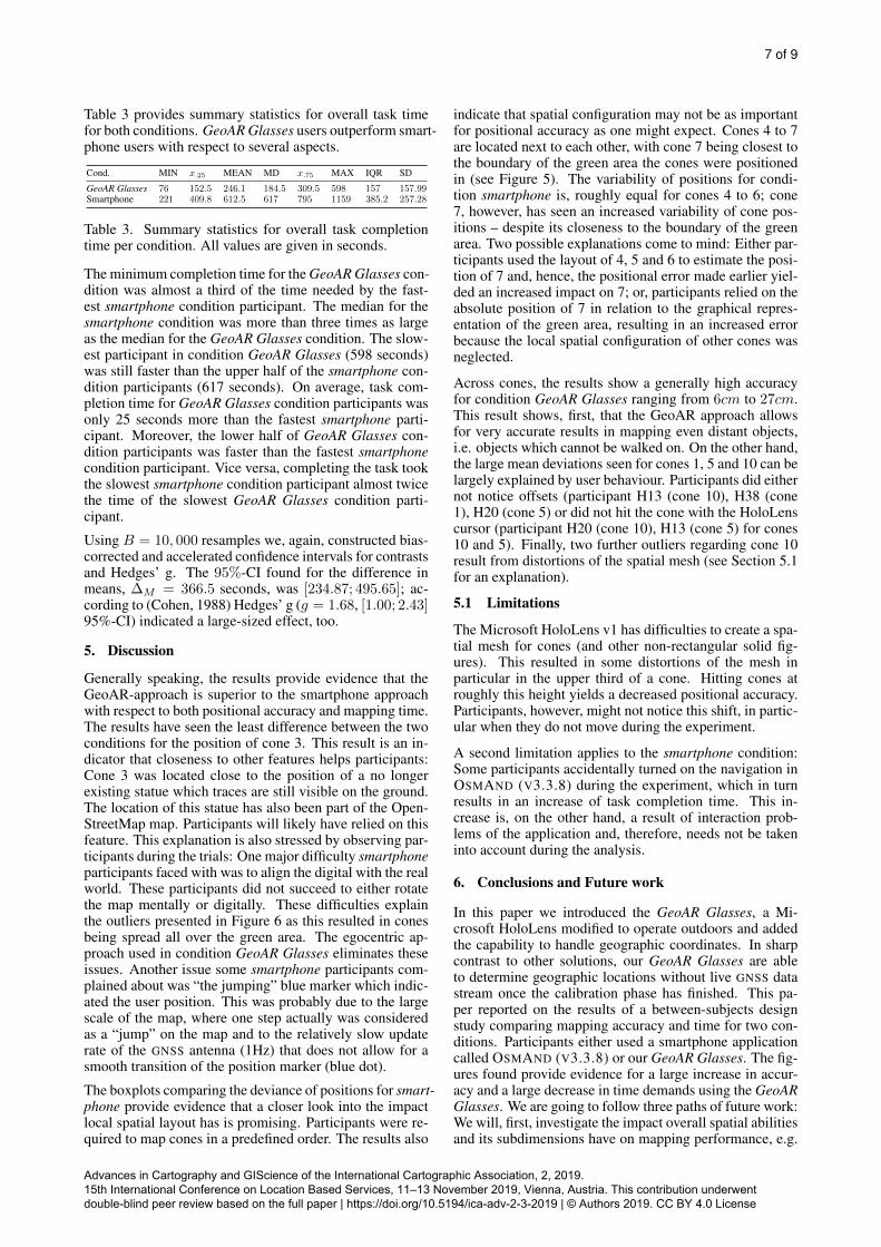
Table 3 provides summary statistics for overall task timefor both conditions. GeoAR Glasses users outperform smart-phone users with respect to several aspects.
Cond. MIN x.25 MEAN MD x.75 MAX IQR SD
GeoAR Glasses 76 152.5 246.1 184.5 309.5 598 157 157.99Smartphone 221 409.8 612.5 617 795 1159 385.2 257.28
Table 3. Summary statistics for overall task completiontime per condition. All values are given in seconds.
The minimum completion time for the GeoAR Glasses con-dition was almost a third of the time needed by the fast-est smartphone condition participant. The median for thesmartphone condition was more than three times as largeas the median for the GeoAR Glasses condition. The slow-est participant in condition GeoAR Glasses (598 seconds)was still faster than the upper half of the smartphone con-dition participants (617 seconds). On average, task com-pletion time for GeoAR Glasses condition participants wasonly 25 seconds more than the fastest smartphone parti-cipant. Moreover, the lower half of GeoAR Glasses con-dition participants was faster than the fastest smartphonecondition participant. Vice versa, completing the task tookthe slowest smartphone condition participant almost twicethe time of the slowest GeoAR Glasses condition parti-cipant.
Using B = 10, 000 resamples we, again, constructed bias-corrected and accelerated confidence intervals for contrastsand Hedges’ g. The 95%-CI found for the difference inmeans, ∆M = 366.5 seconds, was [234.87; 495.65]; ac-cording to (Cohen, 1988) Hedges’ g (g = 1.68, [1.00; 2.43]95%-CI) indicated a large-sized effect, too.
5. Discussion
Generally speaking, the results provide evidence that theGeoAR-approach is superior to the smartphone approachwith respect to both positional accuracy and mapping time.The results have seen the least difference between the twoconditions for the position of cone 3. This result is an in-dicator that closeness to other features helps participants:Cone 3 was located close to the position of a no longerexisting statue which traces are still visible on the ground.The location of this statue has also been part of the Open-StreetMap map. Participants will likely have relied on thisfeature. This explanation is also stressed by observing par-ticipants during the trials: One major difficulty smartphoneparticipants faced with was to align the digital with the realworld. These participants did not succeed to either rotatethe map mentally or digitally. These difficulties explainthe outliers presented in Figure 6 as this resulted in conesbeing spread all over the green area. The egocentric ap-proach used in condition GeoAR Glasses eliminates theseissues. Another issue some smartphone participants com-plained about was “the jumping” blue marker which indic-ated the user position. This was probably due to the largescale of the map, where one step actually was consideredas a “jump” on the map and to the relatively slow updaterate of the GNSS antenna (1Hz) that does not allow for asmooth transition of the position marker (blue dot).
The boxplots comparing the deviance of positions for smart-phone provide evidence that a closer look into the impactlocal spatial layout has is promising. Participants were re-quired to map cones in a predefined order. The results also
indicate that spatial configuration may not be as importantfor positional accuracy as one might expect. Cones 4 to 7are located next to each other, with cone 7 being closest tothe boundary of the green area the cones were positionedin (see Figure 5). The variability of positions for condi-tion smartphone is, roughly equal for cones 4 to 6; cone7, however, has seen an increased variability of cone pos-itions – despite its closeness to the boundary of the greenarea. Two possible explanations come to mind: Either par-ticipants used the layout of 4, 5 and 6 to estimate the posi-tion of 7 and, hence, the positional error made earlier yiel-ded an increased impact on 7; or, participants relied on theabsolute position of 7 in relation to the graphical repres-entation of the green area, resulting in an increased errorbecause the local spatial configuration of other cones wasneglected.
Across cones, the results show a generally high accuracyfor condition GeoAR Glasses ranging from 6cm to 27cm.This result shows, first, that the GeoAR approach allowsfor very accurate results in mapping even distant objects,i.e. objects which cannot be walked on. On the other hand,the large mean deviations seen for cones 1, 5 and 10 can belargely explained by user behaviour. Participants did eithernot notice offsets (participant H13 (cone 10), H38 (cone1), H20 (cone 5) or did not hit the cone with the HoloLenscursor (participant H20 (cone 10), H13 (cone 5) for cones10 and 5). Finally, two further outliers regarding cone 10result from distortions of the spatial mesh (see Section 5.1for an explanation).
5.1 Limitations
The Microsoft HoloLens v1 has difficulties to create a spa-tial mesh for cones (and other non-rectangular solid fig-ures). This resulted in some distortions of the mesh inparticular in the upper third of a cone. Hitting cones atroughly this height yields a decreased positional accuracy.Participants, however, might not notice this shift, in partic-ular when they do not move during the experiment.
A second limitation applies to the smartphone condition:Some participants accidentally turned on the navigation inOSMAND (V3.3.8) during the experiment, which in turnresults in an increase of task completion time. This in-crease is, on the other hand, a result of interaction prob-lems of the application and, therefore, needs not be takeninto account during the analysis.
6. Conclusions and Future work
In this paper we introduced the GeoAR Glasses, a Mi-crosoft HoloLens modified to operate outdoors and addedthe capability to handle geographic coordinates. In sharpcontrast to other solutions, our GeoAR Glasses are ableto determine geographic locations without live GNSS datastream once the calibration phase has finished. This pa-per reported on the results of a between-subjects designstudy comparing mapping accuracy and time for two con-ditions. Participants either used a smartphone applicationcalled OSMAND (V3.3.8) or our GeoAR Glasses. The fig-ures found provide evidence for a large increase in accur-acy and a large decrease in time demands using the GeoARGlasses. We are going to follow three paths of future work:We will, first, investigate the impact overall spatial abilitiesand its subdimensions have on mapping performance, e.g.
Advances in Cartography and GIScience of the International Cartographic Association, 2, 2019. 15th International Conference on Location Based Services, 11–13 November 2019, Vienna, Austria. This contribution underwent double-blind peer review based on the full paper | https://doi.org/10.5194/ica-adv-2-3-2019 | © Authors 2019. CC BY 4.0 License

8 of 9
we try to gain further insights whether highly allocentricoriented people are faster and more accurate in the smart-phone condition than highly egocentric-oriented ones. Inthis context, we will also investigate whether the presenceof correctly mapped entities in the smartphone conditionhas an effect on the mapping accuracy. Second, we are go-ing to analyse the impact of the distance covered duringthe experiment might have on both, positional and config-uration accuracy in the smartphone condition. Third, wewill compare both conditions with respect to task load anduser experience.
References
Azuma, R., Hoff, B., Neely, H. and Sarfaty, R., 1999. Amotion-stabilized outdoor augmented reality system. In:Proceedings IEEE Virtual Reality (Cat. No. 99CB36316),IEEE, pp. 252–259.Baillot, Y., Brown, D. and Julier, S., 2001. Authoring ofphysical models using mobile computers. In: ProceedingsFifth International Symposium on Wearable Computers,IEEE, pp. 39–46.Bivand, R. S., Pebesma, E. and Gomez-Rubio, V., 2013.Applied spatial data analysis with R, Second edition.Springer, NY.Brovelli, M. A., Minghini, M., Molinari, M. E. and Zam-boni, G., 2016. Positional accuracy assessment of theopenstreetmap buildings layer through automatic homo-logous pairs detection: The method and a case study. IS-PRS - International Archives of the Photogrammetry, Re-mote Sensing and Spatial Information Sciences XLI-B2,pp. 615–620.Cohen, J., 1988. Statistical power analysis for the behavi-oral sciences. 2 edn, Academic Press, New York.Efron, B., 1979. Bootstrap Methods: Another Look at theJackknife. The Annals of Statistics 7(1), pp. 1–26.Efron, B., 1987. Better Bootstrap Confidence Intervals.Journal of the American Statistical Association 82(397),pp. 171–185.Fan, H., Zipf, A., Fu, Q. and Neis, P., 2014. Quality assess-ment for building footprints data on openstreetmap. In-ternational Journal of Geographical Information Science28(4), pp. 700–719.Faul, F., Erdfelder, E., Lang, A. and Buchner, A., 2007.G*Power 3: A flexible statistical power analysis programfor the social, behavioral, and biomedical sciences. Beha-vioral Research Methods 39(2), pp. 175–191.Feiner, S., MacIntyre, B., Hollerer, T. and Webster, A.,1997. A touring machine: Prototyping 3d mobile augmen-ted reality systems for exploring the urban environment.Personal Technologies 1(4), pp. 208–217.Fogliaroni, P., D’Antonio, F. and Clementini, E., 2018.Data trustworthiness and user reputation as indicatorsof vgi quality. Geo-spatial Information Science 21(3),pp. 213–233.Gerlanc, D. and Kirby, K., 2015. bootES: Bootstrap EffectSizes. R package version 1.2.Ghilani, C. D., 2017. Adjustment computations: spatialdata analysis. John Wiley & Sons.Goodchild, M., 2007. Citizens as sensors: The world ofvolunteered geography. GeoJournal 69(4), pp. 211–221.Haklay, M., 2010. How good is volunteered geographicalinformation? a comparative study of openstreetmap andordnance survey datasets. Environment and Planning B:Planning and Design 37(4), pp. 682–703.
Hedges, L. V., 1981. Distribution theory for Glass’s estim-ator of effect size and related estimator. Journal of Educa-tional Statistics 6(2), pp. 107–128.Hijmans, R. J., 2019. raster: Geographic Data Analysisand Modeling. R package version 2.9-5.Hollerer, T., Feiner, S., Terauchi, T., Rashid, G. andHallaway, D., 1999. Exploring mars: developing indoorand outdoor user interfaces to a mobile augmented realitysystem. Computers & Graphics 23(6), pp. 779–785.Hothorn, T., Hornik, K., van de Wiel, M. A. and Zeileis,A., 2008. Implementing a class of permutation tests: Thecoin package. Journal of Statistical Software 28(8), pp. 1–23.Kelley, K., 2005. The effects of nonnormal distributions onconfidence intervals around the standardized mean differ-ence: Bootstrap and parametric confidence intervals. Edu-cational and Psychological Measurement 65, pp. 51–69.Li, W., Han, Y., Liu, Y., Zhu, C., Ren, Y., Wang, Y. andChen, G., 2018. Real-time location-based rendering ofurban underground pipelines. ISPRS International Journalof Geo-Information 7(1), pp. 32.Marder-Eppstein, E., 2016. Project tango. In: ACM SIG-GRAPH 2016 Real-Time Live!, ACM, p. 40.McGill, R., Tukey, J. W. and Larsen, W. A., 1978. Vari-ations of box plots. The American Statistician 32, pp. 12–16.Mooney, P. and Minghini, M., 2017. A review of open-streetmap data. In: Mapping and the Citizen Sensor, Ubi-quity Press, pp. 37–59.Munzer, S. and Holscher, C., 2011. Entwicklung undValidierung eines Fragebogens zu raumlichen Strategien.57(3), pp. 111–125.Neis, P., Zielstra, D. and Zipf, A., 2012. The street net-work evolution of crowdsourced maps: Openstreetmap ingermany 2007–2011. Future Internet 4(1), pp. 1–21.OpenStreetMap, 2018. Pick Your Mapping Tech-nique. https://wiki.openstreetmap.org/wiki/Pick_your_mapping_technique. [Online; accessed 13-June-2019].OpenStreetMap, 2019a. Android. https://wiki.openstreetmap.org/wiki/Android. [Online; accessed13-June-2019].OpenStreetMap, 2019b. Armchair Mapping. ht-tps://wiki.openstreetmap.org/wiki/Armchair mapping.[Online; accessed 13-June-2019].Reitmayr, G. and Drummond, T., 2006. Going out: robustmodel-based tracking for outdoor augmented reality. In:ISMAR, Vol. 6, pp. 109–118.Ribeiro, A. and Fonte, C., 2015. A methodology for as-sessing openstreetmap degree of coverage for purposes ofland cover mapping. ISPRS Annals of Photogrammetry,Remote Sensing & Spatial Information Sciences.Senaratne, H., Mobasheri, A., Ali, A. L., Capineri, C.and Haklay, M. M., 2017. A review of volunteered geo-graphic information quality assessment methods. Interna-tional Journal of Geographical Information Science 31(1),pp. 139–167.Wang, F. K., 2001. Confidence interval for the mean ofnon-normal data. Quality and Reliability Engineering In-ternational 17(4), pp. 257–267.Wickham, H., 2016. ggplot2: Elegant Graphics for DataAnalysis. Springer-Verlag New York.Wickham, H. and Henry, L., 2019. tidyr: Easily Tidy Datawith ’spread()’ and ’gather()’ Functions. R package ver-sion 0.8.3.
Advances in Cartography and GIScience of the International Cartographic Association, 2, 2019. 15th International Conference on Location Based Services, 11–13 November 2019, Vienna, Austria. This contribution underwent double-blind peer review based on the full paper | https://doi.org/10.5194/ica-adv-2-3-2019 | © Authors 2019. CC BY 4.0 License
9 of 9
Wickham, H., Francois, R., Henry, L. and Muller, K.,2019. dplyr: A Grammar of Data Manipulation. R packageversion 0.8.1.Zielstra, D., Hochmair, H. H. and Neis, P., 2013. As-sessing the effect of data imports on the completeness ofopenstreetmap–au nited s tates case study. Transactions inGIS 17(3), pp. 315–334.
Advances in Cartography and GIScience of the International Cartographic Association, 2, 2019. 15th International Conference on Location Based Services, 11–13 November 2019, Vienna, Austria. This contribution underwent double-blind peer review based on the full paper | https://doi.org/10.5194/ica-adv-2-3-2019 | © Authors 2019. CC BY 4.0 License