genesis - Garaventa Lift genesis Design AnD PlAnning guiDe enclosure or shaftway vertical platform...
36
www.garaventalift.com GENESIS DESIGN AND PLANNING GUIDE Enclosure or shaftway vertical platform lift for lifting heights up to 14 feet Creating An Accessible World
Transcript of genesis - Garaventa Lift genesis Design AnD PlAnning guiDe enclosure or shaftway vertical platform...

www.garaventalift.com
genesisDesign AnD PlAnning guiDe
enclosure or shaftway vertical platform lift for lifting heights up to 14 feet
Creating An Accessible World

Please note:Dimensions provided in this guide are for REFERENCE ONLY and should not be used for site preparation or construction.

Genesis Enclosure and Shaftway Model Table of Contents
What is a Vertical Platform Lift? ......................................................................................................4
Why a Vertical Platform Lift? ...........................................................................................................4
Design Assistance ............................................................................................................................4
Finishes ...........................................................................................................................................4
How it Works ...................................................................................................................................5
Enclosure Model vs. Shaftway Model ...............................................................................................6
Lifting Heights and Mast Sizes .........................................................................................................7
Leadscrew Drive System ..................................................................................................................8
Hydraulic Drive System ...................................................................................................................9
Platforms .........................................................................................................................................10
Platform Configurations ...................................................................................................................11
Operating Controls .........................................................................................................................12
Optional Features ............................................................................................................................14
Garaventa Style Doors and Gates ....................................................................................................16
Fire Rated Doors and Frames ...........................................................................................................16
Door Locks ......................................................................................................................................17
Door Swings ....................................................................................................................................17
Garaventa Style Door Dimensions ....................................................................................................18
Fire Rated Door Dimensions ............................................................................................................22
Shaftway/Pit and Platform Clear Dimensions ..................................................................................26
Enclosure Base and Pit Dimensions .................................................................................................30
Enclosure Platform Clearances ........................................................................................................31
Base Attachment ............................................................................................................................32
Mast Attachment .............................................................................................................................32
Leadscrew Drive System: Technical Reference.................................................................................34
Hydraulic Drive System: Technical Reference ..................................................................................35

What is a Vertical Platform Lift?The genesis Vertical Platform lift is a cost effective way to transport a passenger in a wheelchair, or someone who has difficulty using stairs. The Genesis vertical platform lift provides a code compliant access solution for lifting heights of up to 4343mm (171”) (check the regulations for your jurisdiction). With a variety of platform configurations, the Genesis is available as a 2 or 3 stop unit that can be operated independently or by an attendant. The genesis is suitable for indoor or outdoor use and is available in a multitude of different colors and finishes so that it blends into any setting.
Why a Vertical Platform Lift?
Cost-effectiveVertical lifts are more cost-effective than an elevator and do not require a machine room to house the electrical and mechanical components.
Blends with EnvironmentA vertical lift is an attractive space saving alternative to a lengthy or winding ramp. Adjacent to stairs or in an area complimentary to your building, these lifts can be finished to compliment the aesthetics of the site.
Meets ADA Requirements (USA)Vertical platform lifts are recognized in the ADA Accessibility guidelines as a means to provide public building access.
Design AssistanceWith over 25 years of experience, garaventa has the expertise to overcome almost any design challenge you face. Please call our Design Hot line with your accessibility challenge.
1-800-663-6556 or +1-604-594-0422
FinishesThe standard finish is electrostatically applied and baked powder coat finish in Satin Grey for the steel panels and champagne anodized aluminum extrusions for the framework. As an option, these components can be painted from the large selection of RAl colors (a global paint color system). Alternatively, the genesis enclosure can be supplied with 5mm (3/16”) bronze tinted or clear Plexiglas panels or 6mm (1/4”) laminated glass panels (supplied by others).As an option garaventa lift also offers graphic imaging and Exotic Finishes. Exotic finishes include brass and stainless effects created with special paint. Textured and speckled paint can be applied to the panels and extrusions. The panels can also be supplied with wood finishes, Formica, architectural metals or any material not exceeding 13mm (1/2”) in thickness.
Outdoor ApplicationsWhen located outdoors, the Genesis is modified to ensure durability and reliable performance. included in the outdoor package are: hot dipped galvanized base, primed mezzanine brackets, sealed electrical box, rubber boots on switches and stainless steel fasteners.
-4-
Design Hot Line: 1-800-663-6556 or +1-604-594-0422
Genesis Design & Planning Guide 15808-Q-DP

Enclosure Model with Standard Straight-Through Configuration Shown
Ramp (required for floor mount units only)
lower Door
Mounting Base
Mastupper gate
Platform
Platform Controls (optional type shown)
grab Rail
How it Works
The genesis vertical lift is offered in a variety of configurations and styles for different accessibility challenges. All versions of the genesis vertical lift operate in the same manner and consists of a complete drive system, a platform with side walls, doors with an interlock system and call stations. The mast houses the electrical and mechanical components that raise and lower the cantilevered
platform. The doors or gates cannot be opened unless the platform is at an appropriate landing. The platform is called to the landing by using the call stations located at each landing. Once at a landing, the door interlock is released and the door can be opened.The genesis vertical lift can be used to provide accessibility either indoors or outdoors and can be installed directly on the floor or in a 76mm (3”) deep pit.
-5-
Design Hot Line: 1-800-663-6556 or +1-604-594-0422
Genesis Design & Planning Guide 15808-Q-DP

Enclosure Model
The genesis is available in two styles, the enclosure Model and the shaftway Model. The enclosure Model consists of a factory supplied mast, platform, doors and factory manufactured walls that enclose the lift. The shaftway Model consists of a mast, platform and doors. The walls enclosing the lift are built by others using dimensions provided by garaventa lift.
Enclosure ModelThe enclosure frame is constructed of champagne color anodized aluminum extrusions. The attractive contoured corner posts allow the fasteners to be hidden and the vertical etched lines enhance the appearance of the lift. Horizontal cross members are fitted into the
Shaftway Model
Anodized Aluminum extrusion Corner Posts
steel, Plexiglas or laminated glass
Panels
Frame Mounted Call station
Anodized Aluminum extrusion Cross
Members
shaftway wall supplied by others
note: For illustration only, both doors are shown open.
Doors
corner posts, securing the enclosure panels. The panels come in a choice of 16 gauge painted galvanized mild steel, 5mm (3/16”) bronze tinted or clear Plexiglas or 6mm (1/4”) laminated glass (by others). The enclosure model is available in a number of optional finishes.
Shaftway Model (Hoistway Style)The Genesis Shaftway unit is designed to fit the essential lift components within your shaftway walls. The genesis shaftway Model can have either aluminum frame doors/gates, fire rated steel doors, or the doors can be supplied by others. All styles of doors/gates have interlocks integrated with our control system.
Enclosure Model vs. Shaftway Model
-6-
Design Hot Line: 1-800-663-6556 or +1-604-594-0422
Genesis Design & Planning Guide 15808-Q-DP

The mast size required for a particular site is determined by the vertical travel required between the upper and lower landings. When the site is measured, the lift height “H” is always defined as the distance from the lower landing (pit or floor) where the lift will sit to the upper landing floor as shown in the diagram below. if the lift is to be mounted directly on the surface of the lower landing and an entry ramp is used, then “H” equals the elevation change
Floor Mount
upper landing
lower landing
H
For shaftway units, a second Tie Back is required on both sides of the mast. Consult garaventa lift. *Hydraulic drive only and split Mast standard with this height.
Mast Size Max. “H” Value Mast Structure Height Mast Tieback Height
GVL - 42 1143mm (45”) 1737mm (68 3/8”) 1572mm (61 7/8”)
GVL - 60 1600mm (63”) 2194mm (86 3/8”) 2029mm (79 7/8”)
GVL - 72 1905mm (75”) 2498mm (98 3/8”) 2333mm (91 7/8”)
GVL - 96 2515mm (99”) 3108mm (122 3/8”) 2943mm (115 7/8”)
GVL - 120 3124mm (123”) 3718mm (146 3/8”) 3553mm (139 7/8”)
GVL - 144 3734mm (147”) 4327mm (170 3/8”) 4162mm (163 7/8”)
GVL - 168* 4343mm (171”)* 4937mm (194 3/8”)* 4772mm (187 7/8”)
Two stop lift in a pit and floor mount application. An optional three stop unit is also available.
Pit Mount
upper landing
lower landing
H
Pit
Pit Depth
3” (76mm)
Based on the measured value of “H” the drive mast is selected as follows:
between the upper and lower landings. if the lift is pit mounted, then the measurement “H” is 76mm (3”) greater than the elevation change between landings. This measurement is crucial for your custom designed lift. Be certain the height you provide is accurate. We recommend using the “as built” dimension.The width of the mast is 998mm (39 1/4”) for all mast heights.
Lifting Heights and Mast Sizes
-7-
Design Hot Line: 1-800-663-6556 or +1-604-594-0422
Genesis Design & Planning Guide 15808-Q-DP
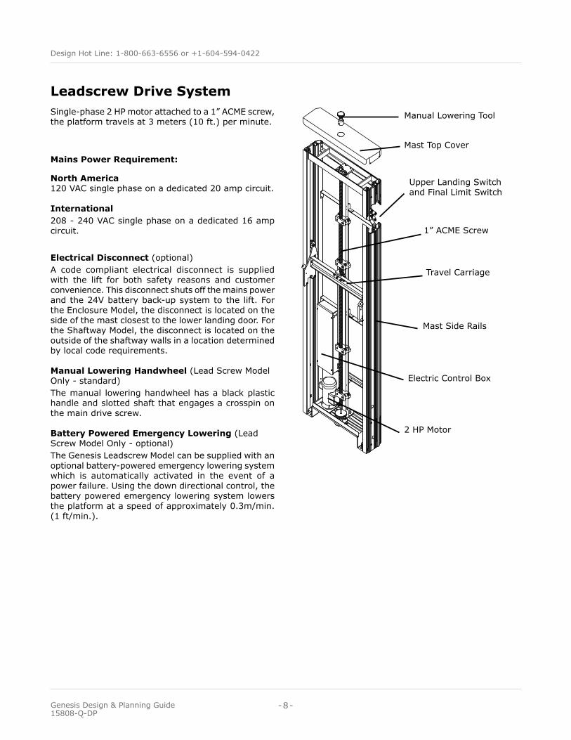
Leadscrew Drive Systemsingle-phase 2 HP motor attached to a 1” ACMe screw, the platform travels at 3 meters (10 ft.) per minute.
Mains Power Requirement:
North America 120 VAC single phase on a dedicated 20 amp circuit. International208 - 240 VAC single phase on a dedicated 16 amp circuit.
Electrical Disconnect (optional)A code compliant electrical disconnect is supplied with the lift for both safety reasons and customer convenience. This disconnect shuts off the mains power and the 24V battery back-up system to the lift. For the enclosure Model, the disconnect is located on the side of the mast closest to the lower landing door. For the shaftway Model, the disconnect is located on the outside of the shaftway walls in a location determined by local code requirements.
Manual Lowering Handwheel (lead screw Model Only - standard)The manual lowering handwheel has a black plastic handle and slotted shaft that engages a crosspin on the main drive screw.
Battery Powered Emergency Lowering (lead screw Model Only - optional)The genesis leadscrew Model can be supplied with an optional battery-powered emergency lowering system which is automatically activated in the event of a power failure. using the down directional control, the battery powered emergency lowering system lowers the platform at a speed of approximately 0.3m/min. (1 ft/min.).
1” ACMe screw
Manual lowering Tool
Travel Carriage
electric Control Box
2 HP Motor
Mast Top Cover
Mast side Rails
upper landing switch and Final limit switch
-8-
Design Hot Line: 1-800-663-6556 or +1-604-594-0422
Genesis Design & Planning Guide 15808-Q-DP

Hydraulic Drive System
Mast Top Cover
upper landing switch and Final
limit switch
Travel Carriage
electric Control Box
Hydraulic Cylinder
Mast side Rails
3.0 HP Motor (2.2 KW)
emergency Manual lowering Valve
Hydraulic Fluid Resevoir
Battery Backup
single-phase 3 HP (2.2 KW), 24VDC hydraulic motor. Continuous mains power and auxiliary power system. The lift connects directly to the building power. The power is reduced to 24 VC to operate the control system and drive the motor. The lift is equipped with an auxiliary power system that enables the lift to operate if mains power is lost. The platform travels between landings at 5.2 meters (17ft.) per minute. *Required for heavy use lifts or lifts equipped with a Fan and Ventilation System.
Mains Power Requirement:
North America - 120 VAC single phase on a dedi-cated 15 amp circuit.International - 208 - 240 VAC single phase on a dedicated 16 amp circuit.
Full Time Battery Operation (optional)For very low use applications and basic units, full time battery operation is appropriate.
Electrical Disconnect (optional)A code compliant electrical disconnect is supplied with the lift for both safety reasons and customer conve-nience. This disconnect shuts off the mains power and the 24V battery back-up system to the lift. The enclosure Model disconnect is on the side of the mast closest to the lower landing door. The shaftway Model disconnect is located on the outside of the shaftway wall in a location determined by local code requirements.
Manual Lowering (Hydraulic Model Only - standard)The manual emergency lowering device consists of a pull knob mounted in a box on the side of the mast. When used, the platform is gently lowered to the landing.
Split Mast (Hydraulic Drive Only - optional)For installation sites where it would be difficult to place the drive mast into position as a single piece, the split mast option is available for gVl-120 and gVl-144. gVl-168 Hydraulic Models are supplied standard with a split mast.
Remote Drive Cabinet (Hydraulic Drive Only - optional)For the ultimate in quiet operation, the drive system can be located up to 3 meters (10 feet) away in a remote drive cabinet.
Mast Heater (Hydraulic Drive Only - optional)For outside installations where cold temperatures are a concern, a mast heater can be installed to protect hydraulic fluid from freezing.
-9-
Design Hot Line: 1-800-663-6556 or +1-604-594-0422
Genesis Design & Planning Guide 15808-Q-DP

The platform is rated for a load of 340 kg. (750 lbs.) and has 1070 mm (42 1/8”) high side walls. The side wall in front of the mast includes a grab rail and platform controls. standard sizes are typically code-compliant for straight through commercial applications. larger sizes may be required for other on/off configurations or to facilitate ease of use.
Shaftway PlatformsThe genesis shaftway Model has 4 platform sizes to meet your requirements:• Compact • Standard • Mid-Size • Large • * Custom sizes available
Platform
grab Railside Walls
Platform Controls
Platforms
Enclosure PlatformsThe genesis enclosure Model has 3 platform sizes to meet your requirements:• Standard • Mid-Size • Large
exact platform dimensions will vary depending upon the model and configuration. For Shaftway Model platform dimensions, see pages 26-29. For enclosure Model platform dimensions, see page 31.
-10-
Design Hot Line: 1-800-663-6556 or +1-604-594-0422
Genesis Design & Planning Guide 15808-Q-DP

Straight Through (180°) Configuration
Clear length
Cle
ar W
idth entry/
exitentry/ exit
On/Off Same Side (360°) Configuration (must have a lift height of 2253mm (88 3/4”)
or greater)
entry/ exit
Clear length
Cle
ar W
idth
Platform Configurations
Entry/Exit ConfigurationsThe genesis is available in various entry/exit configurations. The lift can be supplied as a straight through (180°), a 90° (left or right exit) or an on/off same side (360°) lift configuration. Enclosure model configurations shown.
entry/exit
Clear length
Cle
ar W
idth entry/
exit
90° Configuration
-11-
Design Hot Line: 1-800-663-6556 or +1-604-594-0422
Genesis Design & Planning Guide 15808-Q-DP

Operating ControlsRocker Style Switches (standard)The genesis vertical lift comes equipped standard with rugged indoor/outdoor constant pressure switches. The platform control panel comes standard with an illuminated Audible emergency stop switch. All controls can be fitted with an optional AEMA key switch.
Push Button Control PackageThe Push Button Control Package includes illumi-nated constant pressure directional control switches and platform courtesy lighting. The illuminated push button directional controls also feature tactile braille symbols. Platform courtesy lighting remains illumi-nated for the duration of platform travel and for 10 seconds after the platform arrives at the landing.
Keyed Call Station and Platform Controls (optional)To prevent the use of the lift by unauthorized personnel, the call stations and platform controls can be set up for keyed operation.
Shaftway Frame Mounted Call Stations: Fire Rated DoorsWhen a fire rated door is used the call stations are usually mounted in the steel frame of the door, similar to the garaventa style door call stations. Can be ordered with optional wall mount call stations.
Wall Mounted Call Stationused at lower and/or upper landing
Directional Control switch
Key Switch (optional)
Directional Control switch
Audible illuminated emergency stop/Alarm switch
Key switch (optional)
Platform Controls
Rocker Type Frame Mounted Call Station (standard)
Call/send Rocker switch
Key switch(optional location)
-12-
Design Hot Line: 1-800-663-6556 or +1-604-594-0422
Genesis Design & Planning Guide 15808-Q-DP

Operating Controls (Continued)
Push Button Type Frame Mounted Call Station (Optional)
Call/send Push Buttons
Key switch (optional)
“in use” lamp
Push Button Style Platform Controls (Optional)
Courtesy & emergency light
Directional Controls
emergency stop / Alarm
safety indicator light
Key switch (optional)
Call Station Face Plate Installed on Wall Mount Conduit Box Shown (Optional)
*Surface Mount Call Station Dimension 250mm (9 3/4”) l x 100mm(3 7/8”)W x
23mm (7/8”) D
245
mm
(9
5/8”
)
32 mm (1 1/4”)95 mm (3 3/4”)
Box
Box
245
mm
(9
5/8”
)
100 mm (3 7/8”)
Frame Mounted Fire Door Call Station (Optional Wall Mount Available)
Call / send Buttons
in use lamp
Key switch
-13-
Design Hot Line: 1-800-663-6556 or +1-604-594-0422
Genesis Design & Planning Guide 15808-Q-DP

Optional FeaturesAutodial Telephone in locations where the lift cannot be easily monitored or as required by code in certain jurisdictions, an au-todial telephone can be installed on the platform. The Autodial telephone allows the lift user to make contact with pre-programmed help numbers with the push of a button.
Plexiglas Dome (optional) (Enclosure Model Only) For outdoor applications, a bronze tinted Plexiglas dome can be mounted onto your enclosure. This dome comes standard with a drip rail for rain and condensa-tion.
Fan and Ventilation System (optional) (Enclosure Model with Dome Only)*The fan and ventilation system consists of two exhaust fans, a thermostatic control and a 12 VDC battery backup. The dual fans circulate and completely replace the air in the enclosure every minute when the inside enclosure temperature exceeds 85°F. The Fan and Ventilation system is in accordance with AsMe A17.1 and A18.1 code requirements. *Requires Continuous Mains Power.Note: Codes require a fan and ventilation system for an enclosure lift exposed to direct sunlight fitted with Plexiglas panels and a dome.
Fan and Ventilation system
Plexiglas Dome
Mast
Sloped Roof For directional water run off or for installations where a dome would not be appropriate (i.e. against a building), the lift can be equipped with a sloped steel roof.
Garaventa PDO - Power Door Operator The garaventa Power Door Operator (PDO) allows for automatic door opening and closing. The PDO is obstruction sensing and is clutched which provides a high level of safety and enhances the usability of the lift. The garaventa PDO is suitable for use on garaventa aluminum framed 36”, 42”, and 44” doors and gates.
Arrival Gong and Digital Floor Display Required by code in some parts of europe, the platform mounted arrival gong and Digital Floor Display enhance lift usability by providing audio and visual lift location information.
Dome, Fan & Ventilation System(also shown is the Remote Manual emergency lower-ing knob and access box, available with the Hydraulic Drive)
Ramps (optional)A ramp is used when a 76mm (3”) deep pit cannot be provided. six ramps are available for the genesis, depending on the available space at landings. The ramps are available in slopes of 1:10 and 1:12. Both slopes are available in widths of 1069mm (42”), 1225mm (48 1/4”) or 1375mm (54 1/8”). it is recommended that you use a Power Door Operator and a wall mount call station at landings where a ramp is used.
Lower Landing Entry Ramp (1:12 slope)
974mm (38 3/8”)
76m
m (
3”)
-14-
Design Hot Line: 1-800-663-6556 or +1-604-594-0422
Genesis Design & Planning Guide 15808-Q-DP

Infill Panel Kits (Optional) (Enclosure Model Only)Custom infill panel kits are available to seal off the open space between the enclosure corner post and the building wall, next to the mast. The panel kit will enhance the overall appearance of the genesis. The panel kit includes a frame and panels to fill the area.
Mast Side Wall Panel Kits (optional) (Shaftway Model Only)Custom mast side wall panel kits are available to fill the open space on either side of the mast. The panel kit will enhance the overall appearance of the genesis and seal off this open space.
Custom Bridge
Mast
Mast side Wall Panels
Mast Side Wall Panel Kit
Optional Features (Continued)
existing stairs
Bridge
Barrier
support legs for long bridges (if required)
Bridges (optional)A custom bridge can be supplied for situations where a space must be crossed in order to use the lift. Please contact your garaventa lift representative to discuss these custom fabricated bridges and barrier options.
Infill Panel Kit
Infill Panel
Infill Panel
-15-
Design Hot Line: 1-800-663-6556 or +1-604-594-0422
Genesis Design & Planning Guide 15808-Q-DP

The enclosure and shaftway models utilize garaventa style doors and/or gates. These non-fire rated doors and gates are prehung in a Champagne colored anodized aluminum extrusion frame. The doors and gates are constructed of matching aluminum extrusions with a powder coated 16 gauge galvanized steel kickplate and an upper panel (powder coated 16 gauge galvanized steel, bronze or clear Plexiglas, or laminated glass). garaventa doors are equipped with an offset “D” handle. Custom finishes are also available as an option, please refer to page 2. This non-fire rated door and gate are an attractive alternative to the industrial looking fire rated door.The door height is 2032mm (80”) and the gate height is 1070mm (42 1/8”) and are both available in 2 widths:
• 905mm (35 5/8”) • 1046mm (41 1/8”) • 1109mm (43 5/8”) (for wide side 90° configurations)
Refer to pages 16-19 for further door and door swing dimensions.
The fire rated door and frame is completely prehung and is constructed of 16 gauge steel. The door is supplied with a vision panel and a delayed action door closer. The door has a 1 1/2 hour ‘B’ label fire rating with an integrated interlock system. This door comes standard with a frame mounted 2-button keyed call station.The fire rated door and frame is available in both 906mm (35 5/8”) and 1059mm (41 5/8”) clear door widths. see the Door layouts and Clearances section on pages 20-23 for further door and door swing dimensions.
Fire Rated Doors & FramesGaraventa Style Doors &Gates
-16-
Design Hot Line: 1-800-663-6556 or +1-604-594-0422
Genesis Design & Planning Guide 15808-Q-DP

Garaventa Mechanical Interlock (standard on Genesis Enclosure Model)The garaventa Mechanical interlock is the stan-dard lock used for two stop enclosure lifts that are equipped with garaventa doors and gates. Activated by the movement of the platform, the lock is moni-tored by the safety circuit to ensure the door or gate is properly locked. if the door or gate is not properly locked the lift will only be able to travel 50mm (2”) out of the landing.
Powerlock 2000 (CSA Certified) (standard on Genesis Shaftway Model equipped with Garaventa Door/Gates)The Powerlock 2000 is the lock used in shaftway units with garaventa doors/gates, and are optional for genesis enclosure lifts. The Powerlock 2000 is a 24 VDC solenoid powered interlock that is monitored by the safety circuit to ensure the garaventa door/gate is properly locked.
Locks by OthersGaraventa lifts can be configured to accept interlocks or strikes by others, typically found in fire doors. Con-sult your local garaventa representative for more in-formation.
Door Swings
Gate Positions & Swing Options
Door Locks
-17-
Design Hot Line: 1-800-663-6556 or +1-604-594-0422
Genesis Design & Planning Guide 15808-Q-DP

L
Garaventa Style Door Dimensions - Straight Through (180°) Entry/Exit
Doo
r Pr
ojec
tion
Door Rough Opening
Mast
Doo
r Pr
ojec
tion
47m
m (
1 7/
8”)
Jam
b D
epth
(ty
p.)
Door swing
Door Rough Opening
79mm (3 1/8”) side of Rough Opening to Hinge (typ.)
Door swing
lPlatform C Dim.
Door Door Width R/O* Width R/O* Height Door Swing Door Projection
36” 905mm (35 5/8”) 1098mm (43 1/4”) 2125mm (83 3/4”) 926mm (36 1/2”) 982mm (38 5/8”)
42” 1046mm (41 1/8”) 1240mm (48 7/8”) 2125mm (83 3/4”) 1067mm (42”) 1123mm (44 1/4”)
44” 1109mm (43 5/8”) 1302mm (51 1/4”) 2125mm (83 3/4”) 1104mm (43 1/2”) 1162mm (45 3/4”)
R/O* is Rough OpeningPlatform Size Platform C Dimension
Compact 771mm (30 3/8”)
standard 809mm (31 7/8”)
Mid-size 809mm (31 7/8”)
large 885mm (34 7/8”)
Dimensions are provided for reference only. submittal drawing dimensions should be used for site preparation and construction.
-18-
Design Hot Line: 1-800-663-6556 or +1-604-594-0422
Genesis Design & Planning Guide 15808-Q-DP

Door Door Width R/O* Width R/O* Height Door Swing Door Projection
36” 905mm (35 5/8”) 1098mm (43 1/4”) 2125mm (83 3/4”) 926mm (36 1/2”) 982mm (38 5/8”)
42” 1046mm (41 1/8”) 1240mm (48 7/8”) 2125mm (83 3/4”) 1067mm (42”) 1123mm (44 1/4”)
44” 1109mm (43 5/8”) 1302mm (51 1/4”) 2125mm (83 3/4”) 1104mm (43 5/8”) 1162mm (45 3/4”)
Garaventa Style Door Dimensions - 90° Entry/Exit
R/O* is Rough Opening
LPlatform Size Platform C Dimension
Compact 783mm (30 7/8”)
standard 822mm (32 3/8”)
Mid-size 822mm (32 3/8”)
large 898mm (35 3/8”)
Doo
r Pr
ojec
tion
Mast
47m
m (
1 7/
8”)
Jam
b D
epth
(ty
p.)
Door Rough Opening
79mm (3 1/8”) side of Rough Opening to Hinge (typ.)
Door swing
Doo
r Ro
ugh
Ope
ning
Doo
r sw
ing
Door Projection
l
lPlatform C Dim.
Dimensions are provided for reference only. submittal drawing dimensions should be used for site preparation and construction.
-19-
Design Hot Line: 1-800-663-6556 or +1-604-594-0422
Genesis Design & Planning Guide 15808-Q-DP

Platform Size Platform C Dimension
Compact 771mm (30 3/8”)
standard 809mm (31 7/8”)
Mid-size 809mm (31 7/8”)
large 885mm (34 7/8”)
L
Door Door Width R/O* Width R/O* Height Door Swing Door Projection
36” 905mm (35 5/8”) 1098mm (43 1/4”) 2125mm (83 3/4”) 926mm (36 1/2”) 982mm (38 5/8”)
42” 1046mm (41 1/8”) 1240mm (48 7/8”) 2125mm (83 3/4”) 1067mm (42”) 1123mm (44 1/4”)
44” 1109mm (43 5/8”) 1302mm (51 1/4”) 2125mm (83 3/4”) 1104mm (43 5/8”) 1162mm (45 3/4”)
Garaventa Style Door Dimensions - On/Off Same Side (Entry/Exit Adjacent to Mast)
R/O* is Rough Opening
Doo
r Pr
ojec
tion
Mast
47m
m (
1 7/
8”)
Jam
b D
epth
(ty
p.)
79mm (3 1/8”) side of Rough Opening to Hinge (typ.)
Door swing
Door Rough Opening
lPlatform C Dim.
Dimensions are provided for reference only. submittal drawing dimensions should be used for site preparation and construction.
-20-
Design Hot Line: 1-800-663-6556 or +1-604-594-0422
Genesis Design & Planning Guide 15808-Q-DP

Door Door Width R/O* Width R/O* Height Door Swing Door Projection
36” 905mm (35 5/8”) 1098mm (43 1/4”) 2125mm (83 3/4”) 926mm (36 1/2”) 982mm (38 5/8”)
42” 1046mm (41 1/8”) 1240mm (48 7/8”) 2125mm (83 3/4”) 1067mm (42”) 1123mm (44 1/4”)
44” 1109mm (43 5/8”) 1302mm (51 1/4”) 2125mm (83 3/4”) 1104mm (43 5/8”) 1162mm (45 3/4”)
Garaventa Style Door Dimensions - On/Off Same Side (Entry/Exit Opposite to Mast)
R/O* is Rough Opening
Doo
r Pr
ojec
tion
Mast
47m
m (
1 7/
8”)
Jam
b D
epth
(ty
p.)
79mm (3 1/8”) side of Rough Opening to Hinge (typ.)
Door swing
Door Rough Opening
Dimensions are provided for reference only. submittal drawing dimensions should be used for site preparation and construction.
-21-
Design Hot Line: 1-800-663-6556 or +1-604-594-0422
Genesis Design & Planning Guide 15808-Q-DP

Platform Size Platform C Dimension
Compact 771mm (30 3/8”)
standard 809mm (31 7/8”)
Mid-size 809mm (31 7/8”)
large 885mm (34 7/8”)
Fire Rated Door Dimensions - Straight Through Entry/Exit
R/O* Rough Opening
Door Door Width R/O* Width R/O* Height Door Swing Door Projection
36” 908mm (35 3/4”) 1131mm (44 1/2”) 2102mm (82 3/4”) 937mm (36 7/8”) 1019mm (40 1/8”)
42” 1060mm (41 3/4”) 1283mm (50 1/2”) 2102mm (82 3/4”) 1089mm (42 7/8”) 1171mm (46 1/8”)
L
Doo
r Pr
ojec
tion
Door Rough Opening
Mast
Doo
r Pr
ojec
tion
152m
m (
6”)
Ja
mb
Dep
th (
typ.
)
Door swing
Door Rough Opening
lPlatform C Dim.
109mm (4 1/4”) side of Rough Opening to Hinge (typ.)
Door swing
Dimensions are provided for reference only. submittal drawing dimensions should be used for site preparation and construction.
-22-
Design Hot Line: 1-800-663-6556 or +1-604-594-0422
Genesis Design & Planning Guide 15808-Q-DP

Door Door Width R/O* Width R/O* Height Door Swing Door Projection
36” 908mm (35 3/4”) 1131mm (44 1/2”) 2102mm (82 3/4”) 937mm (36 7/8”) 1019mm (40 1/8”)
42” 1060mm (41 3/4”) 1283mm (50 1/2”) 2102mm (82 3/4”) 1089mm (42 7/8”) 1171mm (46 1/8”)
Fire Rated Door Dimensions - 90° Entry/Exit
Platform Size Platform C Dimension
Compact 783mm (30 7/8”)
standard 822mm (32 3/8”)
Mid-size 822mm (32 3/8”)
large 898mm (35 7/8”)
l
R/O* Rough Opening
Doo
r Pr
ojec
tion
Mast
152m
m (
6”)
Ja
mb
Dep
th (
typ.
)
Door Rough Opening
lPlatform C Dim.
109mm (4 1/4”) side of Rough Opening to Hinge (typ.)
Door swing
Doo
r Ro
ugh
Ope
ning
Doo
r sw
ing
Door Projection
Dimensions are provided for reference only. submittal drawing dimensions should be used for site preparation and construction.
-23-
Design Hot Line: 1-800-663-6556 or +1-604-594-0422
Genesis Design & Planning Guide 15808-Q-DP
Doo
r Pr
ojec
tion
Mast
152m
m (
6”)
Ja
mb
Dep
th (
typ.
)
Door Rough Opening109mm (4 1/4”) side of Rough Opening to Hinge (typ.)
Door swing
lPlatform C Dim.
Door Door Width R/O* Width R/O* Height Door Swing Door Projection
36” 908mm (35 3/4”) 1131mm (44 1/2”) 2102mm (82 3/4”) 937mm (36 7/8”) 1019mm (40 1/8”)
42” 1060mm (41 3/4”) 1283mm (50 1/2”) 2102mm (82 3/4”) 1089mm (42 7/8”) 1171mm (46 1/8”)
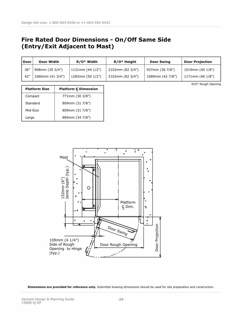
Fire Rated Door Dimensions - On/Off Same Side (Entry/Exit Adjacent to Mast)
R/O* Rough Opening
Platform Size Platform C Dimension
Compact 771mm (30 3/8”)
standard 809mm (31 7/8”)
Mid-size 809mm (31 7/8”)
large 885mm (34 7/8”)
l
Dimensions are provided for reference only. submittal drawing dimensions should be used for site preparation and construction.
-24-
Design Hot Line: 1-800-663-6556 or +1-604-594-0422
Genesis Design & Planning Guide 15808-Q-DP
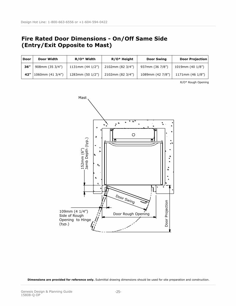
Door Door Width R/O* Width R/O* Height Door Swing Door Projection
36” 908mm (35 3/4”) 1131mm (44 1/2”) 2102mm (82 3/4”) 937mm (36 7/8”) 1019mm (40 1/8”)
42” 1060mm (41 3/4”) 1283mm (50 1/2”) 2102mm (82 3/4”) 1089mm (42 7/8”) 1171mm (46 1/8”)
Fire Rated Door Dimensions - On/Off Same Side (Entry/Exit Opposite to Mast)
R/O* Rough Opening
Doo
r Pr
ojec
tion
Mast
152m
m (
6”)
Ja
mb
Dep
th (
typ.
)
Door Rough Opening109mm (4 1/4”) side of Rough Opening to Hinge (typ.)
Door swing
Dimensions are provided for reference only. submittal drawing dimensions should be used for site preparation and construction.
-25-
Design Hot Line: 1-800-663-6556 or +1-604-594-0422
Genesis Design & Planning Guide 15808-Q-DP

Platform Size
Shaftway/Pit Width
Shaftway/Pit Length Clear Width Clear Length Net Usable Area
Compact 1317mm (51 7/8”) 1295mm (51”) 914mm (36”) 1257mm (49 1/2”) 1.15sq.m. (12.4 sq. ft.)
Standard 1394mm (54 7/8”) 1407mm (55 3/8”) 992mm (39”) 1370mm (53 7/8”) 1.36sq.m. (14.61 sq. ft.)
Mid-Size 1394mm (54 7/8”) 1558mm (61 3/8”) 992mm (39”) 1520mm (59 7/8”) 1.57sq.m. (16.23 sq. ft.)
Large 1546mm (60 7/8”) 1558mm (61 3/8”) 1146mm (45”) 1520mm (59 7/8”) 1.74sq.m. (18.0 sq. ft.)
Shaftway/Pit and Platform Clear Dimensions -Straight Through (180°) Entry/Exit
Straight Through (180°) Entry/Exit Shaftway/Pit and Platform Clear Dimensions
entry / exit
shaftway / Pit Width
Mast76
mm
(3”
) Pi
t D
epth
sha
ftw
ay /
Pit
leng
th
entry / exit
19m
m
(3/4
”)
Clear Width313mm (12 3/8”)
Min. 51mm (2”)
19m
m
(3/4
”)Cle
ar l
engt
h
• Add 38mm (1 1/2”) to pit width if a tie-back rail is used.• 63 1/2mm (2 1/2”) running clearance dimension is included on non entry exit sides• 19mm (3/4”) running clearance dimension is included on entry / exit sides• Shaftway units require (4) mast tie back locations (2 per side).
Dimensions are provided for reference only. submittal drawing dimensions should be used for site preparation and construction.
-26-
Design Hot Line: 1-800-663-6556 or +1-604-594-0422
Genesis Design & Planning Guide 15808-Q-DP

Platform Size
Shaftway/Pit Width
Shaftway/Pit Length Clear Width Clear Length Net Usable Area
Compact 1272mm (50 1/8”) 1316mm (51 7/8”) 940mm (37”) 1208mm (47 1/2”) 1.14sq.m. (12.2 sq. ft.)
Standard 1350mm (53 1/8”) 1428mm (56 1/4”) 1017mm (40”) 1320mm (52”) 1.34sq.m. (14.45 sq. ft.)
Mid-Size 1350mm (53 1/8”) 1579mm (62 1/8”) 1017mm (40”) 1471mm (57 7/8”) 1.50sq.m. (16.11 sq. ft.)
Large 1502mm (59 1/8”) 1579mm (62 1/8”) 1169mm (46”) 1471mm (57 7/8”) 1.72sq.m. (18.0 sq. ft.)
Shaftway/Pit and Platform Clear Dimensions - 90° Entry/Exit
90° Entry/Exit Shaftway/Pit and Platform Clear Dimensions
entr
y /
exit
shaftway / Pit Width
Mast
76m
m (
3”)
Pit
Dep
thsha
ftw
ay /
Pit
leng
th
entry / exit
19m
m
(3/4
”)
19mm (3/4”)
313mm (12 3/8”)
Min
. 51
mm
(2
”)
Clear Width
Cle
ar l
engt
h
• Add 38mm (1 1/2”) to pit width if a tie-back rail is used.• 63 1/2mm (2 1/2”) running clearance dimension is included on non entry exit sides• 19mm (3/4”) running clearance dimension is included on entry / exit sides• Shaftway units require (4) mast tie back locations (2 per side).
Dimensions are provided for reference only. submittal drawing dimensions should be used for site preparation and construction.
-27-
Design Hot Line: 1-800-663-6556 or +1-604-594-0422
Genesis Design & Planning Guide 15808-Q-DP

Platform Size
Shaftway/Pit Width
Shaftway/Pit Length Clear Width Clear Length Net Usable Area
Compact 1317mm (51 7/8”) 1316mm (51 7/8”) 914mm (36”) 1209mm (47 1/2”) 1.10sq.m. (11.89 sq. ft.)
Standard 1394mm (54 7/8”) 1428mm (56 1/4”) 992mm (39”) 1320mm (52”) 1.31sq.m. (14.09 sq. ft.)
Mid-Size 1394mm (54 7/8”) 1579mm (62 1/8”) 992mm (39”) 1471mm (57 7/8”) 1.46sq.m. (15.71 sq. ft.)
Large 1546mm (60 7/8”) 1579mm (62 1/8”) 1144mm (45”) 1471mm (57 7/8”) 1.68sq.m. (18.0 sq. ft.)
Shaftway/Pit and Platform Clear Dimensions - On/Off Same Side (360°) Entry/Exit Adjacent to Mast
On/Off Same Side (360°) Entry/Exit Adjacent to Mast Shaftway/Pit & Platform Dimensions
shaftway / Pit Width
Mast76
mm
(3
”) P
it D
epth
sha
ftw
ay /
Pit
leng
th
entry / exit
19m
m
(3/4
”)
Clear Width313mm (12 3/8”)
Min. 51mm (2”) C
lear
len
gthM
in.
51m
m
(2”)
• Add 38mm (1 1/2”) to pit width if a tie-back rail is used.• 63 1/2mm (2 1/2”) running clearance dimension is included on non entry exit sides• 19mm (3/4”) running clearance dimension is included on entry / exit sides• Shaftway units require (4) mast tie back locations (2 per side).
Dimensions are provided for reference only. submittal drawing dimensions should be used for site preparation and construction.
-28-
Design Hot Line: 1-800-663-6556 or +1-604-594-0422
Genesis Design & Planning Guide 15808-Q-DP

Platform Size
Shaftway/Pit Width
Shaftway/Pit Length Clear Width Clear Length Net Usable Area
Compact 1272mm (50 1/8”) 1337mm (52 7/8”) 940mm (37”) 1159mm (45 5/8”) 1.09sq.m. (11.72 sq. ft.)
Standard 1350mm (53 1/8”) 1448mm (57”) 1017mm (40”) 1271mm (50”) 1.29sq.m. (13.91 sq. ft.)
Mid-Size 1350mm (53 1/8”) 1600mm (63”) 1017mm (40”) 1422mm (56”) 1.45sq.m. (15.57 sq. ft.)
Large 1502mm (59 1/8”) 1600mm (63”) 1169mm (46”) 1422mm (56”) 1.66sq.m. (17.90 sq. ft.)
Shaftway/Pit and Platform Clear Dimensions - On/Off Same Side (360°) Entry/Exit Opposite Mast
On / Off Same Side (360°) Entry/Exit Opposite Mast Shaftway/Pit and Platform Dimensions
entr
y /
exit
shaftway / Pit Width
Mast
76m
m (
3”)
Pit
Dep
thsha
ftw
ay /
Pit
leng
th
Min
. 51
mm
(2
”)
19mm (3/4”)
313mm (12 3/8”)
Min
. 51
mm
(2
”)
Clear Width
Cle
ar l
engt
h
• Add 38mm (1 1/2”) to pit width if a tie-back rail is used.• 63 1/2mm (2 1/2”) running clearance dimension is included on non entry exit sides
• 19mm (3/4”) running clearance dimension is included on entry / exit sides• Shaftway units require (4) mast tie back locations (2 per side).
Dimensions are provided for reference only. submittal drawing dimensions should be used for site preparation and construction.
-29-
Design Hot Line: 1-800-663-6556 or +1-604-594-0422
Genesis Design & Planning Guide 15808-Q-DP

Enclosure Base and Pit Dimensions
Platform Size Base Width Base Length Pit Width Pit Length
Standard 1399mm (55 1/8”) 1505mm (59 1/4”) 1427mm (56 1/8”) 1530mm (60 1/4”)
Mid-Size 1399mm (55 1/8”) 1656mm (65 1/8”) 1427mm (56 1/8”) 1681mm (66 1/8”)
Large 1551mm (61 1/8”) 1656mm (65 1/8”) 1579mm (62 1/8”) 1681mm (66 1/8”)
Enclosure Base and Pit Dimensions
Pit
leng
th
Bas
e le
ngth
Pit Depth 76 mm (3”)
Pit WidthBase Width
Mast
13mm (0.5”) Typical Clearance
• Add 38mm (1 1/2”) to pit width if a tie-back rail is used.
(For leadscrew or Hydraulic Drive system)
Dimensions are provided for reference only. submittal drawing dimensions should be used for site preparation and construction.
-30-
Design Hot Line: 1-800-663-6556 or +1-604-594-0422
Genesis Design & Planning Guide 15808-Q-DP

Configuration Platform Size
Platform Clear Width
Platform Clear Length Net Usable Area
standard 947mm (37 1/4”) 1370mm (53 7/8”) 1.30sq. m. (13.95 sq. ft.)
Mid-size 947mm (37 1/4”) 1520mm (59 7/8”) 1.44sq. m. (15.50 sq. ft.)
large 1099mm (43 1/4”) 1520mm (59 7/8”) 1.67sq. m. (17.98 sq. ft.)
90° Entry/Exit standard 1017mm (40”) 1295mm (51”) 1.28sq. m. (14.17 sq. ft.)
Mid-size 1017mm (40”) 1446mm (56 7/8”) 1.32sq. m. (15.83 sq. ft.)
large 1155mm (45 1/2”) 1446mm (56 7/8”) 1.47sq. m. (18.0 sq. ft.)
standard 947mm (37 1/4”) 1295mm (51”) 1.69sq. m. (13.20 sq. ft.)
Mid-size 947mm (37 1/4”) 1446mm (56 7/8”) 1.23sq. m. (14.74 sq. ft.)
large 1099mm (43 1/4”) 1446mm (56 7/8”) 1.37sq. m. (17.11 sq. ft.)
standard 1017mm (40”) 1220mm (48”) 1.24sq. m. (13.36 sq. ft.)
Mid-size 1017mm (40”) 1372mm (54”) 1.40sq. m. (15.02 sq. ft.)
large 1169mm (46”) 1372mm (54”) 1.60sq. m. (17.27 sq. ft.)
Enclosure Platform Clearances
Straight Through (180°) Entry/ Exit
360° On/Off Same Side (entry/exit
adjacent to mast)
360° On/Off Same Side (entry/exit
oppposite to mast)
-31-
Design Hot Line: 1-800-663-6556 or +1-604-594-0422
Genesis Design & Planning Guide 15808-Q-DP

Mast Attachment
The genesis is supplied with adjustable tie back brackets. These brackets are fastened to the mast and installed into a load bearing support wall. This helps to stabilize the mast. Refer to the loading diagram for the loads that must be supported by the wall.
Attachment Details
Mounting Base (shown with temporary installation legs)
Tie Back Rail Kit (optional) Mast may be fastened
directly to the wall
Mast to Base Connection
Tie Back Bracket
Tie Back Bracket
Base Attachment
Enclosure Model Base
Shaftway Model Base(shown with temporary removable
installation legs)
All Genesis lift bases are fastened to the floor/pit at the lower landing. It is recommended that the floor is a level concrete surface rated for 3500 Psi with a minimum thickness of 102mm (4”). If the floor surface does not meet these specifications, it must be able to withstand the loads shown on the loading diagram.
-32-
Design Hot Line: 1-800-663-6556 or +1-604-594-0422
Genesis Design & Planning Guide 15808-Q-DP

Mast Attachments (Continued)
Y-shaped Tie Back
Brace
u-shaped Tie Back
Brace
U-Shaped Tie Back Brace (Optional) The u Brace wraps around the enclosure lift and is fastened to structural member at the upper landing.
Y-Shaped Tie-Back Brace (Optional)Attached to the mast, the Y Brace forms a triangle of support when it is fastened to a structural member at the upper landing.
Mast Attachment Methods Y Brace and U BraceWhen the adjustable mast tie back bracket cannot be used, mast stabilization can be achieved with the installation of a tie back bracket.
-33-
Design Hot Line: 1-800-663-6556 or +1-604-594-0422
Genesis Design & Planning Guide 15808-Q-DP

Enclosure Platform Sizes:standard enclosure Platform:• 947mm x 1370mm (37 1/4” x 54”)
Optional enclosure Platform: • 947mm x 1522mm (37 1/4” x 60”) - Mid-size• 1099mm x 1522mm (43 1/4” x 60”) - large
Shaftway Platform Sizes:standard shaftway Platform: • 992mm x 1370mm (39” x 54”)
Optional shaftway Platform: • 914mm x 1257mm (36” x 49 1/2”) - Compact• 992mm x 1522mm (39” x 60”) - Mid-size• 1144mm x 1522mm (45” x 60”) - large
Rated Load: 340 kg (750 lbs), with a safety factor of 5
Drive System:Mains Power: 120 VAC single phase on a dedicated 20 amp circuit. Outside n.A. 208-240 VAC single phase on a dedicated 16 amp circuit.
Drive Type: ACMe screw (1” diameter)
Motor: 2 HP, AC Motor. Variable frequency control for smooth start and stop.
Speed: 3 meters (10 ft) per minute at full load
Operating Controls:Keyed Controls: Keyswitch on call stations and platform controls (optional)
Directional Controls: Continuous pressure switches
Control Voltage: 24 VDC
Safety Features:safety nut: safety nut automatically engages if drive nut fails. Platform falls less than 13mm (1/2”) when safety nut engages. engaging safety nut trips the safety circuit.
Door Interlocks: enclosure Model: Mechanical lock with electric contact prevents door from opening unless platform at landing.
shaftway Model: solenoid powered deadbolt with monitoring circuit. Deadbolt stays in the locked position in the event of power failure. Battery backup provided.
emergency stop: stops platform travel and sounds audible alarm.
emergency Operation: equipped standard with a manual lowering wheel. Optional battery powered lowering system available.
Finish:enclosure Frame & Mast sides: Anodized aluminum
Sidewalls & Mast Cover: Baked powder finish on 16 gauge galvanized steel panels – satin grey
Doors: Baked powder finish on 16 gauge galvanized steel panels – satin grey or optional 5mm (3/16”) thick clear or bronze tinted Plexiglas.
Optional Finishes: extrusions and panels can be painted any color in the RAl chart.
Lead Screw Drive System: Technical Reference
-34-
Design Hot Line: 1-800-663-6556 or +1-604-594-0422
Genesis Design & Planning Guide 15808-Q-DP

Enclosure Platform Sizes:standard enclosure Platform:• 947mm x 1370mm (37 1/4” x 54”)
Optional enclosure Platform: • 947mm x 1522mm (37 1/4” x 60”) - Mid-size• 1099mm x 1522mm (43 1/4” x 60”) - large
Shaftway Platform Sizes:standard shaftway Platform: • 992mm x 1370mm (39” x 54”)
Optional shaftway Platform: • 914mm x 1257mm (36” x 49 1/2”) - Compact• 992mm x 1522mm (39” x 60”) - Mid-size• 1144mm x 1522mm (45” x 60”) - large
Rated Load:
340 kg (750 lbs), with a safety factor of 5
Drive System:Mains Power: 120 VAC single phase on a dedicated 15 amp circuit. Outside n.A. - 208-240 VAC single phase on a dedi-cated 16 amp circuit.
Drive Type: Chained Hydraulic (Dual 5/8” Ansi 50 chains)
standard Motor: 3 HP Motor: Continuous mains power and auxiliary battery power
Optional Power supply: 3 HP Motor: 24 VDC from bat-tery system, continuously charged by buildings mains power (suitable for low usage lifts only).
Speed:5.2 meters (17 ft) per minute at full load
Hydraulic Drive System: Technical Reference
Operating Controls:Keyed Controls: Keyswitch on call station and platform controls (optional)
Directional Controls: Continuous pressure switches
Control Voltage: 24 VDC
Safety Features:safety: Monitored slack chain device. Automatically engages if the drive chain fails. Platform falls less than 13mm (1/2”) when the slack chain safety device engages.
Door Interlocks:enclosure Model: Mechanical lock with electric contact prevents door from opening unless platform at landing.
shaftway Model: solenoid powered deadbolt with monitoring circuit. Deadbolt stays in the locked position in the event of power failure. Battery backup provided.
emergency stop: stops platform travel and sounds audible alarm.
emergency Operation: Auxiliary Power system oper-ates the lift in up and down direction.
Finish:enclosure Frame & Mast sides: Anodized aluminum
Sidewalls & Mast Cover: Baked powder finish on 16 gauge galvanized steel panels – satin grey
Doors: Baked powder finish on 16 gauge galvanized steel panels – satin grey or optional 5mm (3/16”) thick clear or bronze tinted Plexiglas.
Optional Finishes: extrusions and panels can be painted any color in the RAl chart.
-35-
Design Hot Line: 1-800-663-6556 or +1-604-594-0422
Genesis Design & Planning Guide 15808-Q-DP

Authorized garaventa lift Representative www.garaventalift.com
Creating An Accessible World
© garaventa li f t . As we are continuously improving our products, specifications outlined in this brochure are subject to change without notice.
Printed in Canada15808-Q-DP