GENESIS 1genesis.web.psi.ch/download/documentation/genesis_manual.pdf · About this Manual This...
53
GENESIS 1.3 User Manual Dec-04
Transcript of GENESIS 1genesis.web.psi.ch/download/documentation/genesis_manual.pdf · About this Manual This...
GENESIS 1.3
User Manual
Dec-04

2
Contents
About this Manual 5
About GENESIS 1.3 7The Particle Equations . . . . . . . . . . . . . . . . . . . . . . . . . . . . . . . . . . 7The Field Equations . . . . . . . . . . . . . . . . . . . . . . . . . . . . . . . . . . . 8Time-Dependent Effects . . . . . . . . . . . . . . . . . . . . . . . . . . . . . . . . . 9Pre- and Postprocessors . . . . . . . . . . . . . . . . . . . . . . . . . . . . . . . . . 10
Compilation, Installation and Execution 13Compilation of the FORTRAN Source Code . . . . . . . . . . . . . . . . . . . . . . 13Compilation of the C++ Source Code . . . . . . . . . . . . . . . . . . . . . . . . . 15Installation . . . . . . . . . . . . . . . . . . . . . . . . . . . . . . . . . . . . . . . . 15
SDDS . . . . . . . . . . . . . . . . . . . . . . . . . . . . . . . . . . . . . . . 15XML . . . . . . . . . . . . . . . . . . . . . . . . . . . . . . . . . . . . . . . . 15HDF5 . . . . . . . . . . . . . . . . . . . . . . . . . . . . . . . . . . . . . . . . 16MPI . . . . . . . . . . . . . . . . . . . . . . . . . . . . . . . . . . . . . . . . 16
Running GENESIS 1.3 . . . . . . . . . . . . . . . . . . . . . . . . . . . . . . . . . . 16
Setting-up Simulations 19Step I - The Magnetic Lattice . . . . . . . . . . . . . . . . . . . . . . . . . . . . . . 19Step II - The Electron Beam . . . . . . . . . . . . . . . . . . . . . . . . . . . . . . . 19Step III - The Radiation Field . . . . . . . . . . . . . . . . . . . . . . . . . . . . . . 20Step IV - Optimization Using the SCAN-Feature . . . . . . . . . . . . . . . . . . . . 21Step V - Time-dependent Simulation . . . . . . . . . . . . . . . . . . . . . . . . . . 21Step VI - External Input for the Magnetic Field . . . . . . . . . . . . . . . . . . . . . 22General Tips . . . . . . . . . . . . . . . . . . . . . . . . . . . . . . . . . . . . . . . 23
Input Parameters 25Undulator Parameters . . . . . . . . . . . . . . . . . . . . . . . . . . . . . . . . . . 25Electron Beam Parameters . . . . . . . . . . . . . . . . . . . . . . . . . . . . . . . 27Radiation Parameters . . . . . . . . . . . . . . . . . . . . . . . . . . . . . . . . . . 28Particle Loading Parameters . . . . . . . . . . . . . . . . . . . . . . . . . . . . . . . 29Mesh Parameters . . . . . . . . . . . . . . . . . . . . . . . . . . . . . . . . . . . . 30Focusing Parameters . . . . . . . . . . . . . . . . . . . . . . . . . . . . . . . . . . . 31Time-Dependence Parameters . . . . . . . . . . . . . . . . . . . . . . . . . . . . . . 32
3
4
Simulation Control Parameters . . . . . . . . . . . . . . . . . . . . . . . . . . . . . 32Scan Parameters . . . . . . . . . . . . . . . . . . . . . . . . . . . . . . . . . . . . . 33Input and Output Control Parameters . . . . . . . . . . . . . . . . . . . . . . . . . . 34
Input and Output Files 39The Main Input File . . . . . . . . . . . . . . . . . . . . . . . . . . . . . . . . . . . 40The Main Output File . . . . . . . . . . . . . . . . . . . . . . . . . . . . . . . . . . 40The Radiation and Particle Output File . . . . . . . . . . . . . . . . . . . . . . . . . 41The Log File . . . . . . . . . . . . . . . . . . . . . . . . . . . . . . . . . . . . . . . 42Reading-in and Dumping the Particle and Radiation Distribution . . . . . . . . . . . . 42The Magnet Description Input and Output File . . . . . . . . . . . . . . . . . . . . . 43The Beam Description File . . . . . . . . . . . . . . . . . . . . . . . . . . . . . . . 46The Radiation Description File . . . . . . . . . . . . . . . . . . . . . . . . . . . . . 48The External Distribution File . . . . . . . . . . . . . . . . . . . . . . . . . . . . . . 49The Time-Record File . . . . . . . . . . . . . . . . . . . . . . . . . . . . . . . . . . 50The SDDS File Format . . . . . . . . . . . . . . . . . . . . . . . . . . . . . . . . . 50The XML File Format . . . . . . . . . . . . . . . . . . . . . . . . . . . . . . . . . . 50The HDF5 File Format . . . . . . . . . . . . . . . . . . . . . . . . . . . . . . . . . 50
The GENESIS 1.3 Algorithm 51
Where to Find Further Information 53

About this Manual
This manual covers the FEL simulation code GENESIS 1.3. It explains how to set-up aninput deck as well as how to extend the capability by using additional input files. The centralpart of this document is the reference list of all input parameters, which are accepted byGENESIS 1.3. Further information about the code can be found at the website
http://pbpl.physics.ucla.edu/ reiche/
In particular the novice user of GENESIS 1.3 can find there sample input files, which is agood starting point for setting-up his own input decks. Anyhow a basic understanding ofFEL physics is recommended for a successful operation of GENESIS 1.3.
Throughout this document different fonts are used to distinguish text from the plain text ofthe manual. The italic font and Greek symbols refer to mathematical and physical constantsor expression, e.g.
E = mc2
Sample input and output files as well as all names referring directly to GENESIS 1.3 arewritten in typewriter-style such as GAMMA0 or XLAMD.
The manual has a short section on the algorithm of GENESIS 1.3. Its purpuse is to let userunderstand, what is calculated and what are the capabilities and limits of GENESIS 1.3. Itis not written to encourage people to modify or extend the code. Anyhow the code is notperfect. If there is a demand to extend the code, please notefy the authors of the code.
5
6 GENESIS 1.3 – Manual
About GENESIS 1.3
GENESIS 1.3 is a time-dependent three-dimensional FEL code. It is focused to simulatesingle-pass free-electron lasers, both FEL amplifier and SASE FEL, although the flexibleinput can be used to easily extend the capacity of GENESIS 1.3 to cover FEL oscillators ormultistage set-ups.
GENESIS 1.3 bears its origin in the steady-state 2D code TDA3D, although they havenothing in common except for some naming convention. GENESIS 1.3 has all the featuresof TDA3D and is intendent as a replacement, in particular that there is no more supportfor TDA3D. For an easier transition GENESIS 1.3 adopted most of the input and outputformat of TDA3D. TDA3D input file will most likely not work.
The code was written by Sven Reiche as a part of the Ph.D. thesis at DESY, Germany, andthen further extended at UCLA and DESY.
The Particle Equations
Macro particles represent the electron beam in all dimension of the 6D phase space. Forconvenience the longitudinal position is replaced by the ponderomotive phase of the particleand the transverse momenta are normalized to mc. The equations of motion are
dθ
dz= k
(1− 1
βz
)+ ku (1)
dγ
dz= −kfcarau
βzγsin(θ + Ψ)− Ez (2)
dx
dz=
px
βzγ(3)
dpx
dz= −qxx + bx +
s
γpy (4)
dy
dz=
py
βzγ(5)
dpy
dz= −qyy + by −
s
γpx (6)
where βz is the electron velocity in z, normalized to the speed of light, k is the radiation wavenumber, ku is the undulator wave number, fc the coupling factor, ar and au are the scalar,
7
8 GENESIS 1.3 – Manual
normalized amplitudes of the radiation and undulator field, Ψ is the phase of the radiationfield, Ez is the electrostatic field, bx and by are the normalized dipole strengths in x and y,qx and qy are the quadrupole field strengths in x and y and s is the solenoid field strength.
The differential equations for energy and phase are solved by a 4th order Runge-Kuttasolver, where the field amplitude of the discretized radiation field and electrostatic field isinterpolated to the particle position.
Distinct to the main undulator field au, the quadrupole and dipole fields combines many fieldsources such as the natural focusing of the undulator, strong focusing quadrupoles, undulatorfield errors and corrector magnets (steering magnets). Per integration step their strength isfixed and the differential equations for the transverse motion is solved analytically. Becausethese equations depend on the particle energy, a higher precision requires to split the pushingof the transverse variables into two half-steps. While the first step relies on the energy valueof the previous iteration, the second uses the updated values of the Runge-Kutta solver forthis iteration.
The Field Equations
Electro-static and electro-magnetic fields are discretized within GENESIS 1.3. The radiationfield is described in the paraxial approximation, where the field is separated into a dominant,fast oscillating term and an amplitude, which slowly varies in magnitude and phase. Thepartial differential equation
[∆⊥ + 2ik
∂
∂z
]u = i
e2µ0
m
∑j
δ(~r − ~rj)fcau
γj
e−iθj
is of parabolic type where u = -iarexp[iΨ] is the complex representation of the radiation field.Note that there is no explicit dependence on t in the differential equation. Time-dependenceeffects are discussed below. The transverse profile of the field is discretized on a Cartesiangrid with uniform spacing. The Alternating Direction Implicit (ADI) solver guarantees anunconditional stable, fast and memory-efficient method to advance the radiation field oneintegration step.
Only the longitudinal component of the electro-static field is taken into account withinGENESIS 1.3, because it acts as a repulsive force during the formation of the micro bunching.On the scope of a single radiation wavelength the field can be assumed to be periodic in theponderomotive phase of the electrons. In the Fourier series expansion of the longitudinalfield the partial different equation of the l coefficient is
[∆⊥ +
l2k2(1 + a2u)
γ2R
]Ez,l = i
ec2µ0lk(1 + a2u)
γ2R
∑j
δ(~r − ~rj)e−ilθj
About GENESIS 1.3 9
where the resonant energy is defined as γR =√
k(1 + a2u)/2ku. With a radial grid centered
to the electron beam centroid position and the azimuthal decomposition of the Fouriercoefficients Ez,l the matrix representation of the partial differential equation is reduced toa tridiagonal matrix, where a fast and memory-efficient solver is applied to. Long-termelectro-static fields (e.g. wake fields) must be calculated externally. They can be importedinto GENESIS 1.3 and applied to equations of motion for the macro particles.
Time-Dependent Effects
GENESIS 1.3 supports two modes of calculations: steady-state and time-dependent simula-tions. Steady-state simulations are base on the assumption of an infinite long electron bunchand radiation field with no longitudinal variation of any parameter. The partial derivativewith respect to the time drops out of the field equations resulting in the parabolic equationshown above. The longitudinal description can be reduced to a single wavelength (bucket)with periodic boundary condition in the ponderomotive phase of the macro particles.
Time-dependent simulations would require to keep the entire radiation field and electronbunch at whole in memory, which easily exceeds the capability of todays best single processormachines. For a solution, which is not bounded to memory constraints, GENESIS 1.3discretizes the radiation field and electron beam in t, referring to them as slices. Becauseinformation on the local electron distribution is carried by the radiation field only in theforward direction (slippage) time-dependent simulations rolls over the electron bunch startingfrom the back. Advancing the radiation field is split into two parts: solving the steady-statefield equation and copying the field to the next slice. Using the method only a single sliceof an electron beam and the radiation field over the total slippage length, which can besignificantly shorter than the bunch length, needs to be kept in memory. Although thespacing of the slices can freely be chosen with GENESIS 1.3, some conditions have to befulfilled for a valid time-dependent simulation.
The propagation of the radiation field has to be done frequently to avoid collective instabili-ties of the steady-state field solver per integration step within a single slice. The characteristicparameter of the FEL interaction is
ρ =1
γ
( aufc
4kuσb
)2Ip
IA
13
where σb is the electron beam radius, Ip is the peak current and IA = 17 kA. The resultinglimitation for the integration step size, being much smaller than the gain length, is
∆z � 1
2kuρ
10 GENESIS 1.3 – Manual
Similar arguments are valid for the separation ∆t of the slices, which is related to theintegration step size by the inequity c∆t ≥ (ku/k)∆z. The constraint for the t-discretizationis therefore
∆t� 1
2ckρ
On the other hand each slice has a thickness of one radiation wavelength λ. The time dis-cretization must be c∆t ≥ λ to avoid overlapping slices. Conflicts might arise if ρ approachesunity. Anyhow in this case the entire FEL model, on which GENESIS 1.3 is based, is notvalid anymore and other simulation tools need to be used to solve this problem.
Very often the time-window ∆T, which is spawn by all slices, covers only a subsection of theelectron beam. Because GENESIS 1.3 does not know anything about the field, which slipsthrough the back of the time-window, it suppresses the output over the first slippage length.To obtain valid output the time window must be at least as long as the slippage length ∆Ts,yielding the constraint
∆T ≥ ∆Ts =ku
k
Lu
c
where Lu is the length of the undulator. In practice the time-window should be significantlylarger than the limit given above to allow a frequency analysis of the radiation. The typicalwidth of the FEL spectrum is ρ. To resolve the spectrum the time-window must fulfill themore stringent constraint
∆T � λ
cρ+ ∆Ts
Once GENESIS 1.3 has allocated enough memory to hold the radiation field over one slippagelength there is no computational limitation imposed on the maximum size of the time-window.
Pre- and Postprocessors
One of GENESIS 1.3 key feature is the extensive support of additional input files as well theimport of modified or process output files of GENESIS 1.3. The generation or processingof these files can be done in the simplest case by hand or by external programs. Althoughthe GENESIS 1.3 website offers several programs for pre- and post-processing they do notofficially belong to the GENESIS 1.3 distribution. Experience shows that these programs
About GENESIS 1.3 11
are mostly customized and specifically bound to a given project or experiment. With thedescription of the GENESIS 1.3 input and output files in this manual and the 3rd partyprograms it should be fairly easy to write programs which fulfills the individual needs of theuser.
GENESIS 1.3 does not support the graphical preparation of the output data due to tworeasons. First, subroutines and function would rely on graphic libraries, which makes itmore difficult to write a platform independent source code. At least for the FORTRANversion, using the original file format, it is the idea to have a code independent on anylibrary. In addition several graphic packages needs to be supported. Otherwise it wouldforce the user to use a graphic package, which does not necessary agree with his choice.
Second, time-dependent simulations generate typically more data than useful to be plotted.It should be possible for the user to filter out the data, he needs. In addition some datahave to be prepared (e.g. Fourier transformation, averaging, binning for histogram plots) forfurther information on the simulated FEL process. To help the GENESIS 1.3 offers severalprograms, which can be the base for the users individual postprocessor.

12 GENESIS 1.3 – Manual
Compilation, Installation and Execution
The C++ version is currently under development. The manual will beupdated, when the source code has been written.
GENESIS 1.3 is distributed as executables for the Linux and Windows platform, as well asthe source code and can be obtained from the official website
GENESIS 1.3 is originally written in FORTRAN but the limit capability of FORTRAN tohandle various input and output formats and a restricted string processing, resulted in aC++ version of the code. The simulated physics of both the C++ and FORTRAN versionis the same and the only difference is in the extended set of file formats, supported by C++.The support of the Fortran stops with the release of the current version.
The compilation section is only important for those who are building GENESIS 1.3 fromthe source code. However the distributed executable might depend on addition libraries notincluded in the distribution. The section on the installion lists all required libraries andenviroment variables for running GENESIS 1.3
Compilation of the FORTRAN Source Code
After unpacking the ’.tar’-archive the directory genesis contains the subdirectory base andextension. The base directory has all the source code, which is needed to run GENESIS1.3, supporting only the original fileformat for input and output. Additional source files arelocated n the extension directory. For FORTRAN only two two extensions are supported:the SDDS file format and the parallelized version, using MPI. By default all extensions aredisabled.
The source code has three different types of source files, indicated by their extension. Fileswith the extension ’.f’ contain all functions, subroutine and local variables, while variablesused in more than one subroutine are grouped into common blocks in the files with theextension ’.cmn’. The last type of files is the single file ’genesis.def’ which defines constantsand function prototypes.
The memory requirement of GENESIS 1.3 can be demanding if time-dependen simulation areperformed or external distribution are imported and kept in memory. The file ’timerec.cmn’holds the information of the time records of the slippage field. NTMAX is the total recordlength, if the slippage filed is stored in memory. If simulation encounters the case thatthis size is too small (GENESIS 1.3 will give an error message) NTMAX has to be increased.
13
14 GENESIS 1.3 – Manual
Another possible way is to export the slippage field to a file. It is done by setting NOFILE
and NTMAX to unity. The file will be deleted at the end of the run. The default setting has atime-record, which demands 160 MByte of free memory - equivalent to 700 records of a gridwith 121 times 121 grid points.
The default settings of GENESIS 1.3 is that the external distribution is read from a filefor every slice. Due to the processing of the input file it can be time-consuming. To keepthe distribution in memory after the first processing two parameters in ’genesis.def’ have tobe change. KEEPDIST has to be set to unity while NDMAX defines the maximum number ofparticles GENESIS 1.3 can hold in memory. Note that 100000 particles correspond to anadditional memory demand of 5 MByte.
The FORTRAN follows in general the F77 standard although it is not fully ANSI-F77compliant. This requires to set specific flags while invoking the compiler. Because compileroption and flags are compiler specific the following list of recommended option just gives ageneral description. Please refer to the manual of your compiler. The distribution contains a’Makefile’, which works with the Absoft FORTRAN compiler under linux. If might be usedas a template for setting up the compiler and linking instruction.
• Optimization should be turned on. In addition if the linker supports a library ofoptimized mathematical function it should be used
• The compiler should warn or preferable generate an error, if variables are not definedexplicitly.
• In general it is a good idea that the compiler issues all warning, but due to the functionprototyping in ’genesis.def’ the warning of unused variable should be disabled.
• GENESIS 1.3 relies on intrinsic double-precision complex numbers for assignment suchas A=DCMPLX(1.d0,0.d0). Most FORTRAN compilers support this by a special VAXor complex option. As an alternative method the DCMPLX(...,...) statements mustbe replaced by CMPLX(...,... kind=8) statements by hand.
• It is recommended to generate a symbolic table (debugger option)
• Some compilers do not automatically treat variables in DATA blocks as static, butGENESIS relies on it. Either enable this option or, as an alternative, make all localvariables static (the size of the executable is increased only by a small amount).
• GENESIS is not written consistently with the same case of all variables through outthe source code. A compiler option should fold all variable and function names to loweror upper case letters if the compiler is case-sensitive.
The SDDS extension of GENESIS 1.3 is in the directory extension/SDDS. Compilation re-quires that the SDDS libraries are installed on the computer. In addition the FORTRANwrapper of SDDS must be linked to the executable to make GENESIS 1.3 work. Unfortu-nately FORTRAN compilers do not support compiler instructions as C++ compiler do. Asa consequnce the base source code must be edited to enable calls to the SDDS part of theprogram. Which files and where to edit are described in the README.SDDS file in the rootdirectory of the genesis distribution.
Compilation, Installation and Execution 15
The MPI version is under development. The manual will be updated, whenthe source code has been finished.
Compilation of the C++ Source Code
The C++ version is under development. The manual will be updated,when the source code has been finished.
Installation
The FORTRAN version of GENESIS is a single executable and can be located anywhere.Under Linux it is preferable in the directory ’/usr/local/bin’.
The C++ version is under development. The manual will be updated,when the source code has been finished.
Both versions can rely on additional libraries, which have to be installed prior to runningGENESIS 1.3. The following lists all possible extensions and links, where further informationcan be obtained.
SDDS
The Self-Describing Data Set (SDDS) is a file format, where a header defines the propertiesof the following data section. The SDDS toolkit allows processing and displaying content ofSDDS files. The offical link is
http://www.aps.anl.gov/asd/oag/oagPackages.shtml
XML
The eXtensible Markup Language (XML) is a popular file format for platform independentdata, mainly in ASCII. XML files can be checked with any XML reader (e.g. InternetExplorer) whether the file does not violates the basic syntax of XML. In addition files canbe validated, so that the data has to fulfill user-defined contraints. The standard for XMLand is associated formats can be found at
http://www.w3c.org
16 GENESIS 1.3 – Manual
GENESIS 1.3 is build with the Xerces XML libraries of the Apache distribution. The librariescan be downloaded from the Xerces website
http://xml.apache.org
HDF5
The Hirachial Data Format (HDF5) is a standard for platform independent binary data. It isbenefical to GENESIS 1.3 because it also allows parallel computation and data compression.The offical website is
http://hdf.ncsa.uiuc.edu/HDF5/
MPI
The Message-Passing Interface is a standard for portable code for parralel computer archi-tecture.
http://www-unix.mcs.anl.gov/mpi/
Running GENESIS 1.3
GENESIS 1.3 requires at least one argument, which is the name of the main input file.In the C++ version it is a command line argument, while the FORTRAN version promtfor the filename. If additional information is needed the program will propt for the missinginformation. The progress as well as warning and error messages are directed to the standardoutput channel or redirect to a file if the ILOG parameter is set.
The C++ versions allows addition comand line arguments for more flexability
The C++ version is currently under development. The manual will beupdated when the source code has been finished.
On UNIX and LINUX platforms GENESIS 1.3 can be easily executed in the background byredirecting the standard input, output and error to files such as
[prompt]$ genesis < GENINPUT > GENOUTPUT 2 >&1 &
Compilation, Installation and Execution 17
where GENINPUT contains line by line all file name, which are normally be prompted forby GENESIS. Any output and error message will be written to the file GENOUTPUT. If ILOGis set a log-file is created and GENOUTPUT remains empty.

18 GENESIS 1.3 – Manual
Setting-up Simulations
This section is a guideline for the novice user of GENESIS 1.3 to set up the main inputcorrectly so that reasonable results can be obtained. It does not cover all aspects of GENESIS1.3. For a more complete reference please check the sections on the input parameters of themain input deck and the usage of additional input and output files. Certain parameters arenot mentioned in this section. If they are omitted in the input deck they fall back to theirdefault values. To obtain a valid input deck in the first place start GENESIS 1.3 and type atthe prompt the filename of a non-existing file. The template file ’template.in’ is generated,which can be edited by any text-editor.
Step I - The Magnetic Lattice
The coarse layout of the undulator is defined by the undulator period length (XLAMD), thenumber of periods (NWIG) and number of modules (NSEC). In this coarse lattice the FODOlattice has to fit in a way that a new undulator module starts after the last FODO cell ofthe section is complete. The length of a FODO cell is determined by FL + DL +2*DRL. Thusthe number of FODO cells per undulator section is given by the next higher integer of theratio between NWIG and the FODO-cell length. As an example with NWIG = 100, NSEC = 2,FL = 4.0, DL = 4.0 and DRL = 8.0 there are 5 FODO cells per section and the two undulatormodules are separated by a gap of 20 undulator periods. If F1ST is set to half the value ofFL the FODO cell starts in the center of the first quadrupole, which simplifies the matchingof the electron beam (ALPHAX, ALPHAY=0).
Set AWD to the same value as AW0. Similar XKX and XKY should agree with the definition ofthe undulator (0.0, 1.0 for planar undulator (IWITYP = 0) or 0.5, 0.5 for helical undulator(IWITYP = 1)). It is recommended that the coupling factor is calculated automatically bysetting FBESS0 to zero. Disable tapering and undulator field errors.
Finally set the integration step with DELZ so that it can resolve FL, DL, DRL and F1ST. In theexample above possible choices are 0.5, 1.0 or 2.0.
Step II - The Electron Beam
After the energy, energy spread and emittances are defined a good value for the beam sizeand the twiss parameters ALPHAX, ALPHAY are critical for a good performance. GENESIS 1.3does not support matching and these values have to be found by external programs. Anyhow
19
20 GENESIS 1.3 – Manual
if the FODO lattice start with half a quadrupole or the field strength of all quadrupoles is setto zero than the beam is going through a waist at the undulator entrance for best matching(ALPHAX, ALPHAY=0). In this case initial runs of GENESIS 1.3 allows for an iterative methodto find the right values for the beam size while ignoring the radiation results.
It is recommended that the number of macro particles (NPART) is at least 2048 (powers oftwo numbers allows a better performance). For simulation of wavelengths below 10 nm thenumber must be even higher to exclude numerical noise.
Step III - The Radiation Field
In an FEL oscillator the radiation parameter are well defined by the seeding radiation fieldand the enclosing cavity. Otherwise (FEL amplifier or SASE FEL) they typically need to beoptimized. Although SASE simulation significantly reduces the impact of the waist positionZWAIST and the Rayleigh length ZRAYL parameters it is recommended as a pre-optimizationstep to run steady-state simulation (ITDP = 0). Thus the following is valid for both, FELamplifier and SASE FEL.
A good estimate of the radiation wavelength is given by the resonant formula
λ =λu
2γ2
(1 + a2
u
)
with λ=XLAMDS, γ=GAMMA0, λu=XLAMD and au=AW0. Anyhow diffraction or emittance effectsmight slightly change the resonant wavelength. The Raylength length should be chosen sothat the initial beam size is similar to the beam size of the gain-guided radiation field inthe exponential amplification regime. If the radiation waist is at the undulator entrance
(ZWAIST=0) the initial beam size is simply given by√
zrλ/π with zr=ZRAYL.
While the input radiation power is a well-defined input parameter for an FEL amplifierits value has to be estimated for steady-state simulation modelling SASE FELs. With thedefinition of the FEL parameter
ρ =1
γ
(aufcλu
8πσb
)2Ip
IA
13
an approximation of an equivalent input power (shot noise power) of the SASE FEL is
Pin = 6√
πρ2 Pb
N√
log(N/ρ)
Setting-up Simulations 21
with fc=FBESS0 or the value GENESIS 1.3 would calculate in the case that FBESS0 is set tozero in the input deck, σb=(RXBEAM + RYBEAM)/2, Ip = CURPEAK, IA = 17 kA, Pb=γIpmc2/e asthe electron beam power and N=Ipλ/ce as the number of electrons per radiation wavelength.
With the parameters for the magnetic field, electron beam and radiation field a run ofGENESIS 1.3 should produce some gain. If the results are satisfying the input deck canbe used for more advanced simulation (field errors, time-dependent simulation). Otherwisefurther optimization of the input parameters is needed.
Step IV - Optimization Using the SCAN-Feature
It can be tedious to find the optimum set of beam energy and radiation wavelength formaximum gain. The scan feature of GENESIS 1.3 helps by performing several runs fordifferent wavelength or energies. To start a scan the scan parameter has to be defined. It issimply done be assigning the name of the parameter to be scanned to SCAN. As an exampleSCAN = ’XLAMDS’ scans over the radiation wavelength. Only two other parameters are neededto complete the input for a scan-run. NSCAN defines the number of runs of the scan whileSVAR limits the scan range. As an example SVAR = 0.1 and NSCAN = 5 will result in fiveruns at wavelengths of 90%, 95%, 100%, 105% and 110% of the input wavelength XLAMDS.The scan feature will automatically adjust the input deck internally to start with the sameinitial conditions at each run.
Step V - Time-dependent Simulation
To enable time-dependence simply set ITDP to one. In addition IALL should be zero,SHOTNOISE 1.0 and PRAD0 zero for SASE simulations. The start-up regime has typicallymodes with strong diffraction. Therefore it is recommended to increase the grid size RMAX0
or DGRID by roughly 50-100%. To compensate the coarser grid NCAR can be increased aswell.
The desired time-window requires some minor calculations. For easier calculation ’time’ isscaled by the speed of light (s=ct). Assuming a time-window, which starts at the tail s0 andends at the head s1 the required number of slices is NSLICE = (s1-s0)/(ZSEP*XLAMDS). Thefirst slice has the position s0. Therefore NTAIL is s0/(ZSEP*XLAMDS). Note that in the frameof GENESIS 1.3 s0 has to be smaller than s1.
The parameter IOTAIL is an indication for GENESIS 1.3 whether radiation is generatedoutside the time-window but might slip at s0 into the time-window while the beam propagatesthrough the undulator. This is the case if only a subsection of the electron beam is simulated.Because GENESIS 1.3 can do only a wild guess about the radiation field which slips intothe time-window the tail part of the time-window is physically incorrect. To exclude these
22 GENESIS 1.3 – Manual
slices in the output IOTAIL should be set to zero. The number of suppressed slices is simplythe number of undulator periods of the entire undulator divided by ZSEP.
As an example we assume a Gaussian beam profile with an rms length of 1 mm (CURLEN =1.e-3) and a radiation wavelength of 5 µm for an undulator with 200 periods. The spacingbetween the slices is ZSEP=2.0. The output should be between -2 mm and 2 mm whichcuts out a part of the bunch (IOTAIL=0). The total number of slices is 400 slice of outputplus 100 suppressed slices (NSLICES=500). The first simulated slices is NTAIL=-300 which isequivalent to s0=-3mm.
In this example the time-window is actually very close to cover the entire beam. With s0=-3mm the local beam current is only 1% of the peak current. It is a good assumption thatthe tail s<s0 will not significantly amplify any radiation. With only 100 more slices theentire bunch can be simulated. The parameters would be now: NSLICE=600, NTAIL=-300and IOTAIL=1.
Step VI - External Input for the Magnetic Field
One of the strength of GENESIS 1.3 is the usage of external input files for a more flexibledescription of the FEL such as a more complicated magnetic lattice. The best way to startusing magnetic field input files is to generate one by GENESIS 1.3. This is done by specifyingin MAGOUTFILE the name of the file to be generated. This file can be edited to set up theundulator. Using the two section undulator from above (AWD=0.85, XLAMD=0.02) the filecontains the lines
...
AW 8.5000E-01 2.0000E-02 100
AW 0.0000E-01 2.0000E-02 20
AW 8.5000E-01 2.0000E-02 100
AW 0.0000E-01 2.0000E-02 20
...
Example: To remove the gaps and to taper the second module so that the field strength is5% smaller change the lines to
...
AW 8.5000E-01 2.0000E-02 120
AW 8.0750E-01 2.0000E-02 120
...

Setting-up Simulations 23
The modified file can then be loaded into GENESIS 1.3 for the next run. The filename of theedited file is assigned to MAGINFILE. It is recommended to remove the parameter MAGOUTFILEfrom the input deck or change the assigned filename before running the simulation. Otherwisethe file is overwritten again. In this case it does not matter but there are some cases (e.g.field errors) where there are subtle difference in the file used for the input and the overwrittenoutput. For more information refer to the section on input and output files.
General Tips
At the end of this section some general hints and tips are listed. There are in no particularorder or relation to each other.
• Time-dependent simulations are very CPU-expensive. To optimize an input deck, tryto do it in steady-state mode (ITDP=0).
• The calculation of the diffraction angle of the radiation field as part of the diagnosticis CPU intensive and not needed for the simulation itself. To speed up the executionit is better to save the radiation field at various locations along the undulator. Thediffraction angle can then be obtained in a post-processing step.
• The output of the particle and field distributions can generate huge output files. Al-though GENESIS 1.3 warns about large output files it does not check the availablespace of the hard disk. Either run GENESIS 1.3, check for warning about large outputfiles and stop the program (if the space is not available) or reduce the size of the outputfile by increasing the value of IPRADI, ISRADI, IPPART and/or ISPART.
• Avoid to use the same parameter several times in the input deck. GENESIS 1.3 willuse the last occurrence in the input deck or might even report an error and quit.
• Check whether space charge has a significant impact on the result of the steady-statecase. Space charge can be disabled by setting NSCZ to zero. If the results are noteffected by the space charge routine time-dependent simulations excluding the spacecharge routine run faster.
• For runs with different field errors change the value of ISEED before each run. Thesame is valid for the phase fluctuation in SASE simulations where IPSEED has to bechanged.
• Although the loading parameters ILDPSI, ILDGAM, ILDX, ILDY, ILDPX and ILDPY needhardly to be changed at all, do not assign the same number to more than one parameter.
• It is recommended to set the VERSION parameter to the latest version number to avoidunexpected behavior (e.g. IDUMP=1 will not dump the particle distribution if VERSIONis smaller than 1.0).
• ZRAYL and ZWAIST are needed to calculated the grid size for the simulation althoughtheir primary meanings are obsolete for SASE simulation. If DGRID is used and PRAD0
is very small than indeed they have no impact on the simulation. Still ZRAYL is requiredto be larger than 0.

24 GENESIS 1.3 – Manual
Input Parameters
The main input file of GENESIS 1.3 is controlled by roughly 100 parameters. Some ofthem become obsolete if additional input files are used. In the case that the main input filecannot be found GENESIS 1.3 creates a template for the main input file and terminates.Parameters, which are not included in the input file, fall back on their default values. Allallowed input parameters and their default values, formats and units are listed below.
Undulator Parameters
AW0 (0.735 – float – unitless)The normalized, dimensionless rms undulator parameter, defined by AW0 = (e/mc)(Bu/ku),where e is the electron charge, m is electron mass, c is speed of light, ku=2π/λu is theundulator wave number, λu is the undulator period. Bu is the rms undulator field with Bu
= Bp/2 for a planar undulator and Bu = Bp for a helical undulator, where Bp is the on-axispeak field.
IWITYP (0 – integer – unitless)Flag indicating the undulator type. A value of zero indicates a planar undulator, any othervalue a helical one.
XKX (0.0 – float – unitless)Normalized natural focusing of the undulator in x. Common values are XKX = 0.0, XKY = 1.0for a planar undulator or XKX, XKY = 0.5 for a helical undulator, but might vary if focusingby curved pole faces is simulated. The values should fulfill the constraint XKX + XKY = 1.0.
XKY (1.0 – float – unitless)Normalized natural focusing of the undulator in x. See XKX for more information.
FBESS0 (0.0 – float – unitless)The coupling factor of the electron beam to the radiation field due to the longitudinal wigglemotion of the electrons. It is 1.0 for a helical undulator and J0(x) - J1(x) for a planarundulator where J0(x), J1(x) are Bessel functions and x = AW02/2(1+AW02). If FBESS0 is setto 0.0 GENESIS 1.3 calculates the value.
XLAMD (2.05e-2 – float – meter)The undulator period length.
NWIG (98 – integer – unitless)The number of periods within a single undulator module. The product of NWIG and XLAMD
defines the length of the undulator module.
25
26 GENESIS 1.3 – Manual
NSEC (1 – integer – unitless)The number of sections of the undulator. Note that a section length in not automaticallyidentical with the undulator module length. GENESIS 1.3 aligns modules to the FODO-lattice. If a module ends within a FODO cell the next module starts with the beginningof the next cell. Sometimes this results in a longitudinal gap between adjacent undulatormodules.
AWD (0.735 – float – unitless)A virtual undulator parameter for the gap between undulator modules. The only purposeof this parameter is to delay the longitudinal motion of the electrons in the same manner asAW0 does within the undulator modules. It is used to keep the electron and radiation phasessynchronize up to the point when the interaction at the next undulator module starts again.AWD has typically the same value as AW0, but might vary for optimum matching between themodules.
WCOEFZ(1) (0.0 – float – meter)Start of undulator tapering. Note that tapering is applied, even the magnetic lattice isdefined by an external file.
WCOEFZ(2) (0.0 – float – unitless)The relative change of the undulator field over the entire taper length (AW(exit) = (1 -WCOEFZ(2)) AW(entrance)). In the case of a multi section undulator GENESIS 1.3 tapersthe magnetic field over the gaps as well, resulting in a jump of the magnetic field AW(z)between two modules.
WCOEFZ(3) (0.0 – float – unitless)The taper model:= 1 for linear taper,= 2 for quadratic taper,or no taper otherwise.
IERTYP (0 – integer – unitless)Type of undulator field errors. Either a uniform (+/-1) or Gaussian (+/- 2) distribution canbe chosen. If IERTYP is negative the errors are correlated to minimize the first and secondfield integral. IERTYP =0 disables field errors. Field errors requires a integration step size ofhalf an undulator period (DELZ = 0.5). Note that field errors are applied even if the magneticlattice is defined by an external file.
DELAW (0.0 – float – unitless)RMS value of the undulator field error distribution. A value of zero disables field errors.
ISEED (-1 – integer – unitless)The initial seeding of the random number generator for field errors.
Input Parameters 27
Electron Beam Parameters
NPART (8192 – integer – unitless)The number of macro particles per slice. NPART must be a multiple of 4*NBINS and smallerthan NPMAX defined in the source file ’genesis.def’.
GAMMA0 (35.2 – float – unitless)The mean energy of the electron beam in terms of the electron rest mass energy.
DELGAM (5.0e-3 – float – unitless)The RMS value of the energy distribution in terms of electron rest mass energy.
RXBEAM (112.1e-6 – float – meter)The rms value in x of the transverse, spatial distribution.
RYBEAM (112.1e-6 – float – meter)The rms value in y of the transverse, spatial distribution.
EMITX (2.0e-6 – float – meter)The normalized rms emittance in x .
EMITY (2.0e-6 – float – meter)The normalized rms emittance in y.
ALPHAX (0.0 – float – unitless)Rotation of the transverse phase space distribution in x according to the standard definitionALPHAX = -<xx’> GAMMA0 / EMITX.
ALPHAY (0.0 – float – unitless)Rotation of the transverse phase space distribution in y. See ALPHAX for more information.
XBEAM (0.0 – float – meter)Transverse position in x of the electron beam at the undulator entrance with respect to theundulator axis.
YBEAM (0.0 – float – meter)Transverse position in y of the electron beam at the undulator entrance with respect to theundulator axis.
PXBEAM (0.0 – float – unitless)Average normalized transverse momentum x of the electron beam at the undulator entrance.The momenta are defined as PXBEAM = βxγ where βx = cvx is the average transverse velocityand γ the Lorenz factor of the electron energy.
PYBEAM (0.0 – float – unitless)Average normalized transverse momentum in y of the electron beam at the undulator en-trance. See PXBEAM for more information.
28 GENESIS 1.3 – Manual
CURPEAK (250.0 – float – Amperes)Peak current of the electron beam. Time-independent simulations enforces a constant cur-rent.
CUTTAIL (-1.0 – float – unitless)Cut in the transverse phase space in measures of the rms size to collimate transverse beamtails/halos. The cut is applied after the loading and beam current is set accordingly to thereduced number of macro particles. It is disabled if the value is negative or the electronbeam is imported from an external file.
CONDITX (0.0 – float – m-1)CONDITX is the correlation strength between the amplitude of the eletron’s betatron oscilla-tion and its energy. If the condition is applied correctly any emittance effects are removedfrom the FEL amplification and the focal strength can be increased. However it requiresa conditioning beamline prior to the FEL to apply the correlation. Refer to the paper ofSessler (A.N. Sessler, et al., Phys. Rev. Lett 68 (1992) 309) for more information.
CONDITY (0.0 – float – m-1)Same as CONDITX but for the correlation in the y-plane.
BUNCH (0.0 – float – unitless)Initial value of the bunching factor, when quite loading is used.
BUNCHPHASE (0.0 – float – rad)Phase of initial bunching, when quite loading is used.
EMOD (0.0 – float – unitless)Initial energy modulation, when quite loading is used. The value is the modulation amplitudein terms of gamma.
EMODPHASE (0.0 – float – rad)Phase of initial energy modulation, when quite loading is used.
Radiation Parameters
XLAMDS (12.852e-6 – float – meter)The resonant radiation wavelength. Due to the bandwidth of time-dependent simulationSASE simulations do not require a very precise value for XLAMDS.
PRAD0 (10.0 – float – Watt)The input power of the radiation field. For SASE simulation PRAD0 should be set to zerovalue or at least well below the shot noise level.
ZRAYL (0.5 – float – meter)The Rayleigh length of the seeding radiation field. ZRAYL is defined as πw0
2/XLAMDS where
Input Parameters 29
w0 is the radius of the optical beam waist. The Rayleigh length is a measure for the diffrac-tion w(z)2 = w0
2(1 + (z - ZWAIST)2/ZRAYL2) and is needed to calculate the size and diver-gence/convergence of the seeding field at the undulator entrance. Because the field size candetermine the grid size it is strongly recommended to supply reasonable numbers for ZRAYLand ZWAIST even for simulation starting from noise.
ZWAIST (0.0 – float – meter)Position of the waist of the seeding radiation field with respect to the undulator entrance.ZWAIST is needed in combination with ZRAYL to calculate the initial radiation field. Notethat a waist position within the undulator (ZWAIST > 0) is only used to determine the initialconvergence. The FEL interaction might significantly change the beam size and diffractionof the radiation field (gain guiding).
Particle Loading Parameters
ILDPSI (7 – integer – unitless)Indices of the Hammersley sequence bases for loading the particle phase. GENESIS 1.3 usesthe first 26 prime numbers as bases. To avoid correlation between the variables each baseshould be different.
ILDGAM (5 – integer – unitless)Hammersley base for loading the energy distribution. See ILDPSI for more information.Note that the loading of the energy distribution is Gaussian and uses two bases (ILDGAM andILDGAM + 1).
ILDX (1 – integer – unitless)Hammersley base for loading the distribution in x. See ILDPSI for more information.
ILDY (2 – integer – unitless)Hammersley base for loading the distribution in y. See ILDPSI for more information.
ILDPX (3 – integer – unitless)Hammersley base for loading the distribution in px. See ILDPSI for more information.
ILDPY (4 – integer – unitless)Hammersley base for loading the distribution in py. See ILDPSI for more information.
ITGAUS (1 – integer – unitless)Defines distribution profile in the transverse variables. The available distributions are:- Gaussian (ITGAUS=1)- Uniform (ITGAUS=2)- Parabolic (otherwise)
IALL (0 – integer – unitless)A non-zero value of IALL enforces that all slices are starting with the same element of the
30 GENESIS 1.3 – Manual
Hammersley sequences. It is recommend for time-dependent simulation excluding shot noise.IALL is set automatically for scans.
IPSEED (-1 – integer – unitless)Initial seed for the random number generator used for particle phase fluctuation (shot noise).GENESIS 1.3 requires a re-initialization of the random number generator to guarantee thesame loading whether magnetic field errors are used or not.
NBINS (4 – integer – unitless)Number of bins in the particle phase. The value has to be at least 4 or larger than (2+2n),depending on whether the bunching at the nth harmonics is needed for space charge calcu-lations or output.
Mesh Parameters
NCAR (151 – integer – unitless)The number of grid points for the radiation field along a single axis. The total number forthe mesh is NCAR2. NCAR must be an odd number to cover the undulator axis with one gridpoint. Do not exceed NCMAX defined in the source file ’genesis.def’.
LBC (0 – integer – unitless)Flag to set the boundary condition for the field solver. The options are Direchlet boundarycondition (LBC = 0) and Neumann boundary condition (otherwise). Anyhow the grid shouldbe chosen large enough so that the choice of LBC should not change the results.
RMAX0 (9.0 – float – unitless)GENESIS 1.3 estimates the size of the grid on which the radiation field is discretized byscaling the averages size of the initial radiation field and beam size with RMAX0. The explicitsize is [-DGRID,DGRID] in both dimensions with DGRID = RMAX0(σr,beam+σr,field). The electronbeam size is the rms sum of RXBEAM and RYBEAM while the radiation field size is calculatedwith ZRAYL and ZWAIST.
DGRID (0.0 – float – meter)Any value larger than zero explicitly sets the grid size, overruling the calculation by theRMAX0-parameter.
NSCZ (1 – integer – unitless)Number of longitudinal Fourier components for space charge calculation. NSCZ must begreater than 0 to include space charge but less than (2NBINS+2) for valid results.
NSCR (1 – integer – unitless)Number of azimuthal modes for space charge calculation.
NPTR (40 – integer – unitless)Number of radial grid points, on which the space charge field is evaluated. The radial axis is
Input Parameters 31
automatically chosen by GENESIS 1.3 to be twice as long as the maximum offset of macroparticles relative to the center of the electron beam. This excludes effects of the boundarycondition even for the case of narrow beams.
Focusing Parameters
QUADF (1.23 – float – Tesla/meter)The field strength of (F-)quadrupoles, focusing in the x-plane.
QUADD (0.0 – float – Tesla/meter)The fields strength of (D-)quadrupoles, defocusing in the x-plane. GENESIS 1.3 automati-cally applies the correct signs to QUADF and QUADD indicating the alternating focusing in theFODO-lattice.
FL (98.0 – float – unitless)Length of the F-quadrupoles in measures of the undulator period. The integration step sizeDELZ must resolve the quadrupole length.
DL (0.0 – float – unitless)Length of the D-quadrupoles in measures of the undulator period.
DRL (0.0 – float – unitless)Drift length between F- and D-quadrupoles in measures of undulator period.
F1ST (0.0 – float – unitless)Position within a FODO cell, where GENESIS 1.3 starts the FODO cell lattice. To startwith a full F-quadrupole set F1ST to zero while a value of FL/2 begins the cell in the middleof the focusing quadrupole.
QFDX (0.0 – float – meter)Maximum transverse misplacement of the quadrupoles in x-direction. A random offset be-tween [-QDFX,QDFX] in x is applied to every quadrupole. Quadrupole position errors aregenerated even if the magnetic field is defined by an external file.
QFDY (0.0 – float – meter)Maximum transverse misplacement of the quadrupoles in y-direction, respectively. See QFDX
for more information.
SOLEN (0.0 – float – Tesla)On-axis field strength of a superimposed solenoid field.
SL (0.0 – float – unitless)Length of solenoid field in measures of undulator period. The solenoid is aligned to thebeginning of each undulator section.
32 GENESIS 1.3 – Manual
Time-Dependence Parameters
ITDP (0 – integer – unitless)A non-zero value enables time-dependent simulation. Time-dependence is not allowed if thescan-feature is enabled.
CURLEN (1.0e-3 – float – meter)Bunch length of the current profile. If CURLEN is positive a Gaussian distribution is generatedwith an rms length given by CURLEN. A negative or zero value yield a constant profile.
ZSEP (1.0 – float – unitless)Separation of beam slices in measures of the radiation wavelength. ZSEP must be a multipleof DELZ.
NSLICE (408 – float – unitless)Total number of simulated slices. It defines the time window of the simulation with NSLICE
* ZSEP * XLAMDS/c. Note that the output does not start with the first slice unless theparameter IOTAIL is set. If NSLICE set to zero it automatically adjust NSLICE and NTAIL
to the time-window given by the external input files (BEAMFILE or DISTFILE). It assumes6 standard deviation for a Gaussian distribution or the absolute value of CURLEN for a stepprofile.
NTAIL (-253 – integer – unitless)Position of the first simulated slice in measures of ZSEP*XLAMDS. GENESIS 1.3 starts withthe tail side of the time window, progressing towards the head. Thus a negative or positivevalue shifts the slices towards the tail or head region of the beam, respectively. For a constantprofile (CURLEN < 0) NTAIL has no impact.
SHOTNOISE (1.0 – float – unitless)GENESIS 1.3 applies a random offset to each macro particle phase to generate the correctstatistic for the bunching factor. Each offset is scaled prior by SHOTNOISE, thus SHOTNOISEcan be set to zero to disable shot noise.
ISNTYP (0.0 – integer – unitless)For VERSION below 1.0 only the Pennman algorighm is used for the shot noise, which is onlycorrect for the fundamental wavelength, but for a higher version the default is the Fawleyalgorithm which applies also the correct shotnoise to all higher harmonics. If the user wantsto use the Pennman algorith at a higher version number (which is not recommended), thevalue of ISNTYP has to be set to a non-zero value.
Simulation Control Parameters
DELZ (1.0 – float – unitless)Integration step size in measure of the undulator period length.

Input Parameters 33
ZSTOP (0.0 – float – meter)Defines the total integration length. If the undulator length is shorter than ZSTOP or ZSTOPis zero or negative, the parameter is ignored and the integration is performed over the entireundulator.
IORB (0 – integer – unitless)Flag for orbit correction. For any non-zero value the offset due to the wiggle motion is takeninto account for the interaction between electron beam and radiation field. The correctionis not included in the output values for the beam centroid position.
ISRAVG (0 – integer – unitless)If set to a non-zero value the energy loss due to spontaneous synchrotron radiation is includedin the calculation.
ISRSIG (0 – integer – unitless)If set to a non-zero value the increase of the energy spread due to the quantum fluctuationof the spontaneous synchrotron radiation is included in the calculation.
ELOSS (0.0 – float – eVolt/meter)Externally applied energy loss of the electron beam.
VERSION (0.1 – float – unitless)Used for backward compatibility of the input decks. Some parameters might change theirbehavior for older versions of GENESIS 1.3. The current version is 1.0.
Scan Parameters
ISCAN (0 – integer – unitless)Selects the parameter for a scan over a certain range of its value:
1. GAMMA0
2. DELGAM
3. CURPEAK
4. XLAMDS
5. AW0
6. ISEED
7. PXBEAM
8. PYBEAM
9. XBEAM
10. YBEAM
34 GENESIS 1.3 – Manual
11. RXBEAM
12. RYBEAM
13. XLAMD
14. DELAW
15. ALPHAX
16. ALPHAY
17. EMITX
18. EMITY
19. PRAD0
20. ZRAYL
21. ZWAIST
22. AWD
23. BEAMFILE
24. BEAMOPT
25. BEAMGAM
The last three enable a user-defined scan, where a steady-state run is performed for eachentry of the supplied BEAMFILE. BEAMOPT differs from BEAMFILE that it automaticallyadjust XLAMDS according to the resonance condition and the beam energy, defined in theBEAMFILE. The BEAMGAM option is similar to BEAMFILE, but overwrites the value of energywith GAMMA0 from the main input file.
SCAN (’ ’ – string)By supplying the parameter name to scan over it overrules the setting of ISCAN.
NSCAN (3 – integer – unitless)Number of steps per scan.
SVAR (0.01 – float – unitless)Defines the scan range of the selected scan parameter. The parameter is varied between(1-SVAR) and (1+SVAR) of its initial value. One exception is the scan over ISEED where therandom number generator is not reinitialized.
Input and Output Control Parameters
IPHSTY (1 – integer – unitless)Generate output in the main output file at each IPHSTYth integration step. To disable outputset IPHSTY to zero.
Input Parameters 35
ISHSTY (1 – integer – unitless)Generate output in the main output file for each ISHSTYth slice.
IPPART (0 – integer – unitless)Write the particle distribution to file at each IPPARTth integration step. To disable outputset IPPART to zero. The filename is the same of the main outputfile + the extension ’.par’.
ISPART (0 – integer – unitless)Write the particle distribution to file for every ISPART slice.
IPRADI (0 – integer – unitless)Write the field distribution to file at each IPRADIth integration step. To disable output setIPRADI to zero. The filename is the same of the main outputfile + the extension ’.fld’.
ISRADI (0 – integer – unitless)Write the field distribution to file for every ISRADI slice.
IOTAIL (0 – integer – unitless)If set to a non-zero value the output time window is the same as the simulated time window.Otherwise the output for the first slices covered by the slippage length is subpressed. Neededfor bunches which are completely covered by the time-window.
OUTPUTFILE (’ ’ – string)The name of the main output file. The prompt for the output filename at the beginning ofa GENESIS 1.3 run will be suppressed.
MAGIN (0 – integer – unitless)If set to a non-zero value the user is prompted to type in the file name containing a explicitdescription of the magnetic field.
MAGOUT (0 – integer – unitless)Similar to MAGIN to write out the magnetic field lattice used for the simulation.
MAGINFILE (’ ’ – string)Defines a file, which contains the magnetic field description, bypassing the interactive requestof MAGIN.
MAGOUTFILE (’ ’ – string)Defines the file to which the magnetic field lattice is written to, bypassing the interactiverequest of MAGOUT.
IDUMP (0 – integer – unitless)If set to a non-zero value the complete particle and field distribution is dumped at theundulator exit into two outputfiles. The filenames are the filename of the main output fileplus the extension ’.dpa’ and ’.dfl’, respectively.
IDMPFLD (0 – integer – unitless)Similar to IDUMP but only for the field distribution.
36 GENESIS 1.3 – Manual
IDMPPAR (0 – integer – unitless)Similar to IDUMP but only for the particle distribution.
BEAMFILE (’ ’ – string)Specifying a file containing a lookup table for the electron beam parameters at differentposition along the bunch.
RADFILE (’ ’ – string)Specifying a file containing a lookup table for the seeding radiation pulse at different positionalong the bunch.
DISTFILE (’ ’ – string)If DISTFILE is defined, the 6d distribution is imported into GENESIS 1.3 and used to loadthe phase space. The quiet start algorithm is bypassed.
NDCUT (0 – integer – unitless)When loading a slice, only particles of the external distribution are used, which falls withina small time-window centered around the current position of the slice. If NDCUT has avalue larger than zero the width is calculated by (tmax-tmin)/NDCUT, where tmax and tmin aredetermined, while scanning through the particle distribution. If NDCUT is zero, the time-window is adjusted, so that in average NPART/NBINS particles fall in each slice.
FIELDFILE (’ ’ – string)Defines the file containing the field distribution. The distribution is directly imported intothe arrays, holding the field and the time-records.
ALIGNRADF (0 – integer – unitless)When the FIELDFILE feature is used than Genesis 1.3 aligns the radiation field to the electronbeam so that the radiaiton field is one ful slippage behind the electron beam. In this casethere is no unphysical calculation because the field which slips through the back into thefirst electron slice is fully defined. However this alignment depends on the undulator length.To disable the automatic alignment ALIGNRADF has to be set to a non-zero value. If thisis the case the last slice of the radiaiton field is aligned with the last electron slice. Fieldslices, which slips into the first electorn slice and which is not defined by the FIELDFILE isgenerated by the internal method of using the fundamental Gauss-Hermite mode
OFFSETRADF (0 – integer – unitless)If the automatic alignment of the radiaiton field is disabled by setting ALIGNRADF to a non-zero value, the default alignment is that the first slice of the radiaiton field overlaps withthe first slice of the electron beam. However the relative position can be controlled byOFFSETRADF. The value of OFFSETRADF defines the number of slice to skip before filling itfor the first electorn slice. E.g. a value of 4 will uses the 5th slice for the simulation of thefirst slice. slices one to 4 will be used to fill up the slippage field. If Genesis 1.3. requireto fill a slice which is not defined by the FIELDFILE then it uses the internal method of afundamental Gauss-Hermite mode.
Input Parameters 37
PARTFILE (’ ’ – string)Defines the file containing the particle distribution. The distribution is directly importedinto the arrays holding the particle variables.
CONVHARM (1 – integer – unitless)When the particle distribution is imported from a PARTFILE Genesis 1.3 allows the up-conversion to a higher harmonics. The harmonic number is specified with CONVHARM and hasa defulat value of 1, corresponding to no up-conversion. The user has to make sure that inthe input deck XLAMDS is adjusted, according to the new wavelength.
MULTCONV (0 – integer – unitless)If an imported particle distribution from a PARTFILE is up-converted to a higher harmon-ics the dault behavior is that the number of slices is preserved. This requires that ZSEPisadjusted together with XLAMDS. However if frequency resolution is a problem then a par-ticle distribution can be converted and used multiple times to keep ZSEP constant. Thedisadvantage is that the CPU execution time is increased as well.
IBFIELD (0.0 – float – Tesla)When the PARTFILE features is used the imported particle distribution can be trackedthrough a generic 4 magnet chicane before running the Genesis simulation. The chicaneconsists out of 4 bending magnets of the field strength IBFIELD and length IMAGL separatedby 5 drifts of length IDRIL. If the field strength of the magnet is set to zero the feature of achicane is disabled (default behavior)
IMAGL (0.0 – float – meter)The length of each bending magnet of the chicane. If the magnet length is set to zero butIDRIL is not the resulting beam line correspond to a simple drift of the length 5 times IDRIL.
IDRIL (0.0 – float – meter)The length of the 5 drift lengths of the magnetic chicane (three between the magnets andone before and after the magnets).
ILOG (0 – integer – unitless)If set to a non-zero value all further run-information and error messages are redirect to a logfile. The name is the main output file name plus the extension ’.log’.
FILETYPE (’ORIGINAL’ – string)Indication of the file type of all output files.
NHARM (1 – integer – unitless)Defines the number of harmonics in the bunching factor to be calculated for output purposes.
LOUT (1 1 1 1 1 0 1 1 1 1 1 0 0 0 0 0 0 0 0 – array of integers – unitless)Defines, which parameter is included in the main output file:
1. radiation power
38 GENESIS 1.3 – Manual
2. logarithmic derivative of the power growth
3. power density at the undulator axis
4. radiation phase at the undulator axis
5. transverse radiation size
6. rms diffraction angle of the radiation
7. beam energy
8. bunching factor
9. beam size in x
10. beam size in y
11. error in energy conservation
12. beam position in x
13. beam position in y
14. energy spread
15. on-axis field intensity in the far field zone
16. bunching at the 2nd harmonic
17. bunching at the 3rd harmonic
18. bunching at the 4th harmonic
19. bunching at the 5th harmonic
20. bunching phase of the 1st harmonic
21. bunching phase of the 2nd harmonic
22. bunching phase of the 3rd harmonic
23. bunching phase of the 4th harmonic
24. bunching phase of the 5th harmonic
Note that the calculation of the diffraction angle is very CPU intensive. It is recommendedto save some radiation profile distributions and apply the Fourier transformation in thepost-processing part.
FFSPEC (0 – integer – unitless)To calculate a spectrum a post-processing step requires amplitude and phase, which arewriten to the output file, defined by LOUT of column 3 and 4. The values depend on thechoice of FFSPEC. If the value is equal the near field on-axis intensity and phase is written,while for a negative value it is the same but in the far field zone. For a positive value thenear field intensity is replaced by the total radiation power, assuming transverse coherence.
Input and Output Files
The capability of GENESIS 1.3 can widely be extended by additional input and output files.In total GENESIS 1.3 depends on up to 14 files including such files containing the magneticfield or a sample phase space distribution of the electron beam.
For all runs the main input file is mandatory. It contains the vast majority of the informationneeded to run the simulation. Besides the main output file, which is always created, the maininput files defines, whether additional input and output files are read or written. All outputfiles except for the magnetic output file, uses the filename of the main output file as theroot for their filenames and appends a three letter filename extension. Input files can haveindependent filenames, which are defined in the main input. The main output file and themagnetic input and output files are not needed to be specified in the input file. GENESISprompts for the name if necessary.
Genesis 1.3 has support for different file formats, depending on the programming languageand built of the executable. The original file format is always supported. Input files areautomatically checked for file formats, which are supported by the executable. If GENESIS1.3 cannot identify any special format, it assumes the original file format and starts processingthe file. The file format of output files are set by the input parameter FILETYPE. Requestfor unsupported file formats will cause an error message and the termination of GENESIS1.3
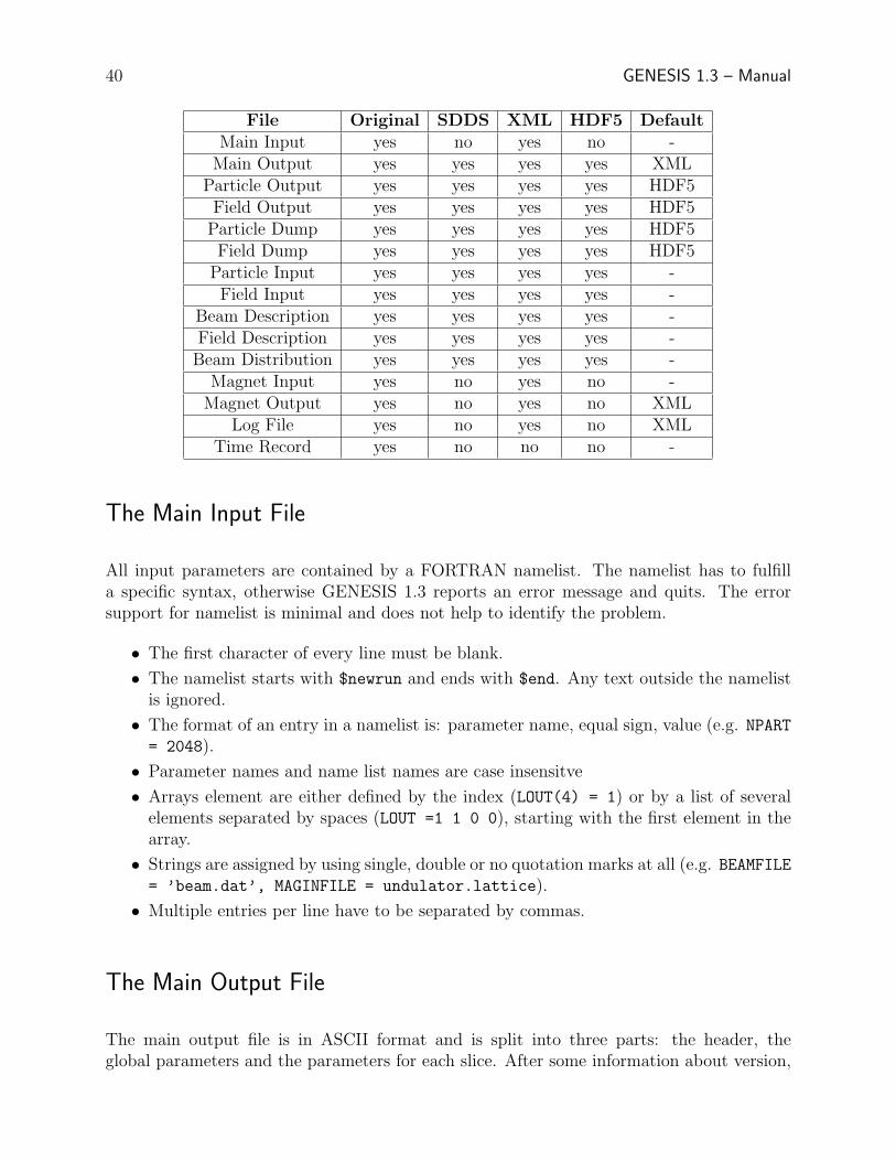
Besides the principle support of a specific file format, certain input and output files are notsuitable for all file formats. The following table lists all files and the implicit support forthem. The last column is the default filetype of output files for the C++ version of Genesisif the filetype is not explicitly defined. If that file format is not supported GENESIS 1.3 fallsback to the original file format as default. The FORTRAN default is the original format forall output files.
It is strongly recommended that the original file format is not used, because it is of allformats the least platform-independent format. Also if more than one record of the electronor field distribution is written, the SDDS and HDF5 file formats yield much smaller file sizes.The XML output is always ASCII and the base64 encoding is not supported.
In the following all individual file are described for the original file format. All other fileformats share the same content of information as the original but might have also additionalinformation for more self-consistent sets of data files. The differnece and addition for theother file formats are explained in the last sections of this chapter.
39
40 GENESIS 1.3 – Manual
File Original SDDS XML HDF5 DefaultMain Input yes no yes no -
Main Output yes yes yes yes XMLParticle Output yes yes yes yes HDF5Field Output yes yes yes yes HDF5Particle Dump yes yes yes yes HDF5Field Dump yes yes yes yes HDF5
Particle Input yes yes yes yes -Field Input yes yes yes yes -
Beam Description yes yes yes yes -Field Description yes yes yes yes -Beam Distribution yes yes yes yes -
Magnet Input yes no yes no -Magnet Output yes no yes no XML
Log File yes no yes no XMLTime Record yes no no no -
The Main Input File
All input parameters are contained by a FORTRAN namelist. The namelist has to fulfilla specific syntax, otherwise GENESIS 1.3 reports an error message and quits. The errorsupport for namelist is minimal and does not help to identify the problem.
• The first character of every line must be blank.
• The namelist starts with $newrun and ends with $end. Any text outside the namelistis ignored.
• The format of an entry in a namelist is: parameter name, equal sign, value (e.g. NPART= 2048).
• Parameter names and name list names are case insensitve
• Arrays element are either defined by the index (LOUT(4) = 1) or by a list of severalelements separated by spaces (LOUT =1 1 0 0), starting with the first element in thearray.
• Strings are assigned by using single, double or no quotation marks at all (e.g. BEAMFILE= ’beam.dat’, MAGINFILE = undulator.lattice).
• Multiple entries per line have to be separated by commas.
The Main Output File
The main output file is in ASCII format and is split into three parts: the header, theglobal parameters and the parameters for each slice. After some information about version,
Input and Output Files 41
platform and name of the input file, a namelist repeats all input parameters. It is possibleto rerun GENESIS 1.3 with the output file because the header fulfills the requirement of avalid input file. Still header part several auxiliary parameters are listed which describes thefollowing data set as well as some information about additional output for the radiation fieldand particle distribution (see below). These information can be used by any postprocessorto correctly read the output files.
The global parameters are mainly the position along the undulator for each output and thecorresponding undulator and quadrupole field at that position.
For each slice an entire table is written containing a header and the main body. The headerlists the slice number, the local current and the column names. In scan mode the currentis replaced by the value of the scan parameter. The data follows directly the header. Therows correspond to the z-positions given in the block of the global parameters. The size ofthe table is controlled by the LOUT parameter.
The Radiation and Particle Output File
As an addition to the main output file the distribution of the radiation field or the electronbeam can be written to binary files. The file names are derived from the file name of themain output file by adding the extension ’.fld’ and ’.par’, respectively. In most cases thesefiles are large even in their binary format (ASCII output would increase the file size byroughly a factor of 3). The output order is similar to the output of the main output file witha consecutive output along the undulator. The output for a single slice at a certain positionwithin the undulator is referred to as a record in z. All z records of a single slices form arecord in t. The total number of z- and t-records are given in the header of the main outputfile.
Each particle record in z starts with the energy of all particles followed by the output ofthe particle phases, positions in x and y and the momenta in x and y. The momenta arenormalized to mc.
The radiation field record contains the real part of the discretized field and then the imaginarypart. The field is normalized so that the square sum of the real and imaginary part yieldsthe field intensity with respect to a unit area. To obtain the real intensity each value has tobe devided by the area each grid point covers. The order of the grid points starts with thelower left corner (x,y < 0) along the x-axis. At the end of each row in x it jumps back in xand advance y by one step.

42 GENESIS 1.3 – Manual
The Log File
If the log feature is enables any output of genesis to the screen is redirect into a log-file.The purpose of the log-file is to support background calculation of GENESIS 1.3. Thus theexecution will be terminated if GENESIS 1.3 needs further information (e.g. file names foradditional input files). The log feature is more reasonable for the C++-version of GENESIS1.3 because the input file name can by supplied as a command line argument while startingGENESIS 1.3. The FORTRAN version still needs to request the input file name thus defyingthe purpose of a background job. Anyhow to start it as a background job type the command:’genesis < geninput > genoutput 2>&1 &’
where geninput is a simple ASCII file containing the file name of the input file. The filegenoutput will catch any output, which cannot be handled by the log file (e.g. error mes-sages). In the ideal case genoutput contains only the initial text lines for requesting theinput file name.
Reading-in and Dumping the Particle and Radiation Distribution
With the parameters IDMPFLD and IDMPPAR set to a non-zero value the field and particledistribution is written to binary files for each slice at the end of the undulator. The file formatis similar to that of the particle and field output file (see above) with a few differences. Theparticle phase is absolute and not relative to the radiation phase. The radiation field hasthe same format as in the radiation output files (see above), representing the intensity ifreal and imaginary parts are summed in square, but instead listing real and imaginary partseparately, the field dump has the complex value listed instead (pairs of real and imaginarypart). The radiation field escaping the last slice is added to the output so that the radiationfield, escaping first, is the last record in t. Note that there is only one record in z for bothfiles.
These files can be used to simulate the effect of a bunch compressor or a monochromator andthen reused as an input for a consecutive run of GENESIS 1.3. To indicate GENESIS 1.3to skip the internal generation of the radiation field or particle distribution the file names ofthese files are given as the input values for FIELDFILE and PARTFILE.
There are some restrictions of using these files.
• The number of slices must be equal or smaller than the number of t-records in theparticle file
• The grid spacing and the radiation wavelength must be the same to guarantee energyconservation of the radiation field.
• The number of slices plus the length of the slippage field record must be smaller thanthe number of t-records in the field file.
Input and Output Files 43
While the first point is obvious the second needs some explanation. Because the radiationslips through several electron slices the time-window of the radiation field must be largerthan the time-window of the simulated electron beam. It is extended by the slippage lengthNSLP, which is the number of radiation slices which slips through a single electron beam sliceover the entire undulator length. The length is the undulator length divided by XLAMD andZSEP and rounded to the lower integer. The radiation initially seen by the first beam sliceis the NSLP+1 record of the radiation input file. The records between the first and NSLPthslice are copied in the time-record. During the integration these slices are pushed into thelocation of the simulated electron slice. Generally speaking the time window of the radiationfield is shifted forwards with respect to the time window of the electron beam during theintegration. In the case that the second GENESIS 1.3 run uses a longer undulator thanthe first run, which dumped the radiation field and beam distribution, the number of beamslices has to reduced to match the file length of the input radiation field.
Note that Genesis does not check for consistency. The field dump is associated to a certaingrid size and radiation wavelength. If a field is imported for a simulation, where these valuesdiffers, the energy of the field is not conserved.
The Magnet Description Input and Output File
The magnet description file is in ASCII format and contains the explicit profile of all mag-netic components or a subset of it. After processing the file GENESIS 1.3 recalculates theundulator length and adjusts the number of integration steps. Field errors and tapering isalways enforced, when the corresponding parameters in the main input file are set. Thisallows that different sets of field errors or taper gradients can be simulated while using onlya single input file. The output of the magnetic lattice, if requested, includes the field lattice,seen by particle of the simulation. Even if field error and taper is disabled the output filemight differ from the input file in the format, but not in the content.
If any line of the input file starts with a space the content of the entire line is treated as acomment. Also any character beyond the 30th position is ignored. These two restrictionsdoes not apply for the C++ version. In general the processing of the file is case insensitive.
Each line is categorized either as
• content line,
• comment line,
• command line,
• information line.
The content line actually holds information about the magnetic structure. The format ofeach line depends on the version of the input file. There is a difference between the current
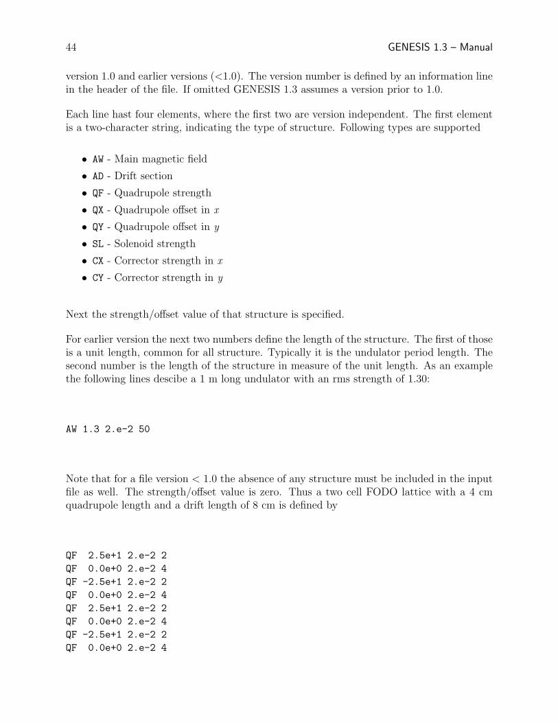
44 GENESIS 1.3 – Manual
version 1.0 and earlier versions (<1.0). The version number is defined by an information linein the header of the file. If omitted GENESIS 1.3 assumes a version prior to 1.0.
Each line hast four elements, where the first two are version independent. The first elementis a two-character string, indicating the type of structure. Following types are supported
• AW - Main magnetic field
• AD - Drift section
• QF - Quadrupole strength
• QX - Quadrupole offset in x
• QY - Quadrupole offset in y
• SL - Solenoid strength
• CX - Corrector strength in x
• CY - Corrector strength in y
Next the strength/offset value of that structure is specified.
For earlier version the next two numbers define the length of the structure. The first of thoseis a unit length, common for all structure. Typically it is the undulator period length. Thesecond number is the length of the structure in measure of the unit length. As an examplethe following lines descibe a 1 m long undulator with an rms strength of 1.30:
AW 1.3 2.e-2 50
Note that for a file version < 1.0 the absence of any structure must be included in the inputfile as well. The strength/offset value is zero. Thus a two cell FODO lattice with a 4 cmquadrupole length and a drift length of 8 cm is defined by
QF 2.5e+1 2.e-2 2
QF 0.0e+0 2.e-2 4
QF -2.5e+1 2.e-2 2
QF 0.0e+0 2.e-2 4
QF 2.5e+1 2.e-2 2
QF 0.0e+0 2.e-2 4
QF -2.5e+1 2.e-2 2
QF 0.0e+0 2.e-2 4

Input and Output Files 45
For the latest version the unit length is declared once in the header of the file and is manda-tory. The third number is the length of the structure in measure of the unit length, whilethe last number is the distance to the previous element of the same kind, again inmeasureof the unit length. The definition of the FODO cell becomes now
? VERSION=1.0
? UNITLENGTH=2.e-2
QF 2.5e+1 2 0
QF -2.5e+1 2 4
QF 2.5e+1 2 4
QF -2.5e+1 2 4
The usage of the lines, starting with the question marks, are explainded below. A commentline is indicated by a -sign as its first character. The remaining content of the line is ignored.Similar lines, which do not contain any printable characters (spaces excluded) are treated ascomment lines.
A command line starts with an exclamation mark. For the magnetic field only two commandsare recognized. The first command !LOOP = x marks the beginning of a loop where x isthe number of loops to be performed. Note that there can be an arbitrary number of spaceson both sides of the equal sign as long as the entire line is no longer than 30 characters. Theend of the loop is indicated by !ENDLOOP. Loops cannot be nested and starting a new loopbefore the current loop is not closed will cause an error and the termination of GENESIS1.3. The following lines define the same FODO lattice as above but this time with 10 cells
? VERSION=1.0
? UNITLENGTH=2.e-2
QF 2.5e+1 2 0
! LOOP=9
QF -2.5e+1 2 4
QF 2.5e+1 2 4
! ENDLOOP
QF -2.5e+1 2 4
The last class of input lines is information lines, which helps GENESIS 1.3 to process the filecorrectly. These lines have to start with a question mark. One example is to set the versionnumber with ?VERSION = n.m for compatibility reason, where m.n is the version number.Currently only versions below 1.0 and below are supported. The remaining other option is
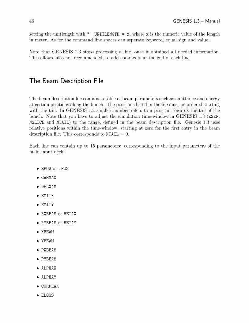
46 GENESIS 1.3 – Manual
setting the unitlength with ? UNITLENGTH = x, where x is the numeric value of the lengthin meter. As for the command line spaces can seperate keyword, equal sign and value.
Note that GENESIS 1.3 stops processing a line, once it obtained all needed information.This allows, also not recommended, to add comments at the end of each line.
The Beam Description File
The beam description file contains a table of beam parameters such as emittance and energyat certain positions along the bunch. The positions listed in the file must be ordered startingwith the tail. In GENESIS 1.3 smaller number refers to a position towards the tail of thebunch. Note that you have to adjust the simulation time-window in GENESIS 1.3 (ZSEP,NSLICE and NTAIL) to the range, defined in the beam description file. Genesis 1.3 usesrelative positions within the time-window, starting at zero for the first entry in the beamdescription file. This corresponds to NTAIL = 0.
Each line can contain up to 15 parameters: corresponding to the input parameters of themain input deck:
• ZPOS or TPOS
• GAMMA0
• DELGAM
• EMITX
• EMITY
• RXBEAM or BETAX
• RYBEAM or BETAY
• XBEAM
• YBEAM
• PXBEAM
• PYBEAM
• ALPHAX
• ALPHAY
• CURPEAK
• ELOSS
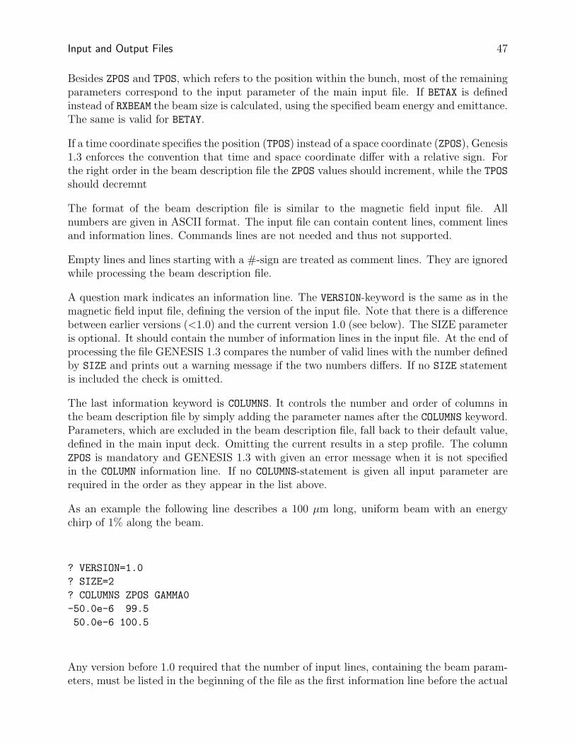
Input and Output Files 47
Besides ZPOS and TPOS, which refers to the position within the bunch, most of the remainingparameters correspond to the input parameter of the main input file. If BETAX is definedinstead of RXBEAM the beam size is calculated, using the specified beam energy and emittance.The same is valid for BETAY.
If a time coordinate specifies the position (TPOS) instead of a space coordinate (ZPOS), Genesis1.3 enforces the convention that time and space coordinate differ with a relative sign. Forthe right order in the beam description file the ZPOS values should increment, while the TPOSshould decremnt
The format of the beam description file is similar to the magnetic field input file. Allnumbers are given in ASCII format. The input file can contain content lines, comment linesand information lines. Commands lines are not needed and thus not supported.
Empty lines and lines starting with a #-sign are treated as comment lines. They are ignoredwhile processing the beam description file.
A question mark indicates an information line. The VERSION-keyword is the same as in themagnetic field input file, defining the version of the input file. Note that there is a differencebetween earlier versions (<1.0) and the current version 1.0 (see below). The SIZE parameteris optional. It should contain the number of information lines in the input file. At the end ofprocessing the file GENESIS 1.3 compares the number of valid lines with the number definedby SIZE and prints out a warning message if the two numbers differs. If no SIZE statementis included the check is omitted.
The last information keyword is COLUMNS. It controls the number and order of columns inthe beam description file by simply adding the parameter names after the COLUMNS keyword.Parameters, which are excluded in the beam description file, fall back to their default value,defined in the main input deck. Omitting the current results in a step profile. The columnZPOS is mandatory and GENESIS 1.3 with given an error message when it is not specifiedin the COLUMN information line. If no COLUMNS-statement is given all input parameter arerequired in the order as they appear in the list above.
As an example the following line describes a 100 µm long, uniform beam with an energychirp of 1% along the beam.
? VERSION=1.0
? SIZE=2
? COLUMNS ZPOS GAMMA0
-50.0e-6 99.5
50.0e-6 100.5
Any version before 1.0 required that the number of input lines, containing the beam param-eters, must be listed in the beginning of the file as the first information line before the actual
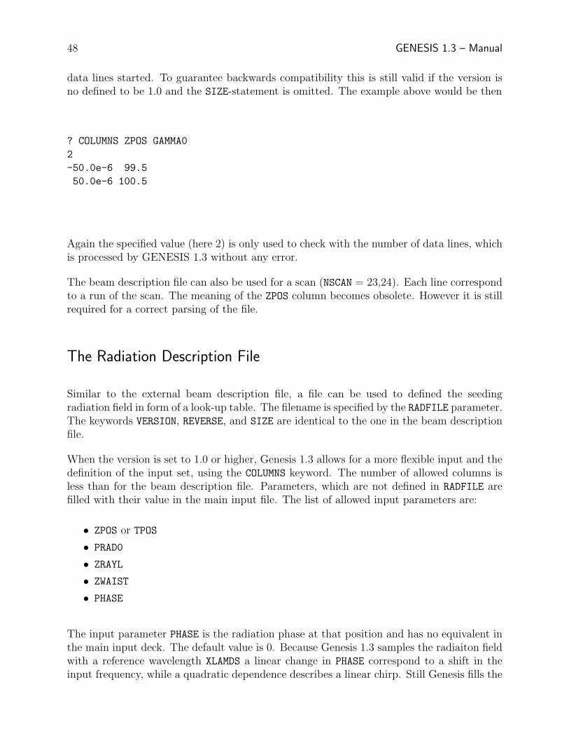
48 GENESIS 1.3 – Manual
data lines started. To guarantee backwards compatibility this is still valid if the version isno defined to be 1.0 and the SIZE-statement is omitted. The example above would be then
? COLUMNS ZPOS GAMMA0
2
-50.0e-6 99.5
50.0e-6 100.5
Again the specified value (here 2) is only used to check with the number of data lines, whichis processed by GENESIS 1.3 without any error.
The beam description file can also be used for a scan (NSCAN = 23,24). Each line correspondto a run of the scan. The meaning of the ZPOS column becomes obsolete. However it is stillrequired for a correct parsing of the file.
The Radiation Description File
Similar to the external beam description file, a file can be used to defined the seedingradiation field in form of a look-up table. The filename is specified by the RADFILE parameter.The keywords VERSION, REVERSE, and SIZE are identical to the one in the beam descriptionfile.
When the version is set to 1.0 or higher, Genesis 1.3 allows for a more flexible input and thedefinition of the input set, using the COLUMNS keyword. The number of allowed columns isless than for the beam description file. Parameters, which are not defined in RADFILE arefilled with their value in the main input file. The list of allowed input parameters are:
• ZPOS or TPOS
• PRAD0
• ZRAYL
• ZWAIST
• PHASE
The input parameter PHASE is the radiation phase at that position and has no equivalent inthe main input deck. The default value is 0. Because Genesis 1.3 samples the radiaiton fieldwith a reference wavelength XLAMDS a linear change in PHASE correspond to a shift in theinput frequency, while a quadratic dependence describes a linear chirp. Still Genesis fills the
Input and Output Files 49
slices with a fundamental Gaussian mode. If higher modes are desired the user has to creathis own distribution on a grid and import them with the FIELDFILE option.
A new keyword is OFFSET allows to shift the radiaiton field with respect to the electronbeam. The value is the offset in meters. Note that for version 1.0 and higher, Genesis 1.3alligns first the defined input range so that the first line in the look-up table is at zero of theinternal, co-moving coordinate system.
The External Distribution File
GENESIS 1.3 support external phase space distribution, generate by other simulation codes(e.g. ELEGANT). To enable the feature the input parameter DISTFILE points to a file,which contains the particle distribution of the entire bunch.
The format is ASCII and for each particle all 6 coordinates must be supplied per line.Additional information can be added per particle (such as particle ID), which is ignored byGENESIS 1.3 in the current version.
Similar to the beam description file and the magnetic field input file the functionality isextended by additional file information or comments.
Lines starting with the #-sign and empty lines are ignored. The question mark indicatesinformation lines. The VERSION and the SIZE keywords are the same as in the beam descrip-tion file. Again if the version is smaller than 1.0 and the SIZE keyword is omitted the firstline, containing data, must be the size of the following data set. This value is used to checkfor consistency and completeness of the distribution file. A required information the chargein Coulombs, defined by the CHARGE keyword
The order of the 6 coordinates and additional values is set by the COLUMNS keyword followedby the names of each column in the data set. In the current version the total number ofcolumns is limited to ten, but only those columns are used where the column name matchesone of the following recognized keywords:
• X - position in x in meters
• PX or XPRIME - momentum in x normalized to mc or divergence in x, respectively
• Y - position in y in meters
• PY or YPRIME - momentum in y normalized to mc or divergence in y, respectively
• T or Z - longitudinal position in seconds or meters, respectively
• P or GAMMA - total momentum or energy, normalized to mc or mc2, respectively.
50 GENESIS 1.3 – Manual
The longitudinal position has to be defined exclusive either to be T or Z. The same is valid forthe other pairs listed above. If not all 6 dimensions are given GENESIS 1.3 will terminateand report an error message. Note that GENESIS follows the rule that the longitudinalposition is reversed if a time is specified by the T column. In this case smaller numberscorrespond to particle in the tail of the distribution.
The default behavior of GENESIS 1.3 corresponds to the lines:
? VERSION = 0.1
? COLUMNS X PX Y PY T P
Note that with this default behaviour the first data line must be the number of particles (=information lines) in the distribution file.
The Time-Record File
This is an file, which is created by GENESIS if the NOFILE parameter is set to a non-zerovalue in the file ’timerec.cmn’. It is only for internal use and will be deleted, when GENESIS1.3 terminates.
The SDDS File Format
Currently not implemented. The manual will be updated, when the sourcecode, supporting new file formats, has been written
The XML File Format
Currently not implemented. The manual will be updated, when the sourcecode, supporting new file formats, has been written
The HDF5 File Format
Currently not implemented. The manual will be updated, when the sourcecode, supporting new file formats, has been written
The GENESIS 1.3 Algorithm
Has to be written
51

52 GENESIS 1.3 – Manual
Where to Find Further Information
GENESIS 1.3
S. Reiche, ”Numerical Studies for a Single Pass High Gain Free-Electron Laser”, DESYprint, DESY-THESIS-2000-012 (2000)
http://pbpl.physics.ucla.edu/ reiche (official website)
FEL BasicsE.L. Saldin, E.A. Schneidmiller and M.V.Yurkov, ”The Physics of Free Electron Lasers”,Springer, (2000)J.B. Murphy and C. Pellegrini, ”Introduction to the Physics of the FEL”, Proceedings ofthe South Padre Island Conference, Springer (1986) 163
Numeric BasicsW.H. Press, S.A. Teukolsky, W.T. Vetterling and B.P. Flannery, ”Numerical Recipes inFORTRAN”, Cambridge University Press, (1988)W.F. Ames, ”Numerical Methods for Partial Differential Equations”, Academic Press (1996)
FORTRAN, C++J.M. Ortega, ”An Introduction to FORTRAN for Scientific Computing”, Oxford UniversityPress (1994)B. Stroustrup, ”C++ Programming Language”, Addison-Wesley (1997)
XML, SDDSM. Birbeck et al., ”Professional XML”, Wrox (2001)M. Borland, ”User’s Guide for SDDS Toolkit Version 1.20”,
http://www.aps.anl.gov/asd/oag/manuals/SDDStoolkit
53