Generic Milling Manual - Unauthorized Access
140
Denford Limited Birds Royd Brighouse West Yorkshire HD6 1NB Tel: +44 (0)1484 712264 Fax: +44 (0)1484 722160 EMail: [email protected] Generic Milling Manual COMPUTERISED MACHINES AND SYSTEMS
Transcript of Generic Milling Manual - Unauthorized Access
0.0CONTENTS -
Denford LimitedBirds RoydBrighouseWest YorkshireHD6 1NBTel: +44 (0)1484 712264Fax: +44 (0)1484 722160EMail: [email protected]
GenericMillingManual
COMPUTERISED MACHINES AND SYSTEMS
Notes
This file is the Adobe Acrobat version of the Denford Generic DOS Milling Software manual. File Optimisation: On-screen display and printing. Graphics: resampled to 600 dpi. Language: European English. Paper size: A4 (210mm x 297mm). Denford Customer Services. Tel: +44 (0) 1484 722733 e-mail: customer_services @denford.co.uk

0.0 - CONTENTS
NOTES.

0.0CONTENTS -
Table of Contents
Notes ..........................................................0-2Introduction..................................................0-5Using the Manual ..........................................0-6Basic Components ........................................0-7Operating the Desktop Tutor Control Panel .......0-9Context Sensitive Help...................................0-17
Switching on an Integrated Controller Machine ....1-1Switching on a PC controlled Machine .............1-3PC Machines - Hard Disk Software Loading ......1-5PC Machines - Floppy Disk Software Loading ....1-6Closing the Control Software ..........................1-7Control Software - Main Menu ........................1-8
Automatic Search for the Machine Datum Point 2-1
Setting the Datum Plate .................................3-1Using Miteebite Clamps .................................3-5How does a Miteebite Clamp work?.................3-6Clamping work using the Miteebite Clamps ......3-7
Changing the Tool with an ATC ........................4-1Changing the tool manually ............................4-2Setting the Tool Offsets - Introduction ..............4-3Setting the Work Datum X and Y Co-ordinates ....4-4Setting the Tool Offset Z Co-ordinates .............4-10Setting a 'Global' Z value ...............................4-15Tool Offsets - Setting the Tool Radius value .......4-16Tool Offsets - Warning ...................................4-17Offset Files - Control Menu.............................4-19Offset Files - Load .........................................4-22Offset Files - Save .........................................4-24Changing the Drive Directory - Offset Files .......4-25Saving Offset Files on a Changed Drive ............4-27Loading Offset Files on a Changed Drive ..........4-28
CNC Files - Menu ..........................................5-1CNC Files - Load ...........................................5-2CNC Files - New ...........................................5-4CNC Files - Save ...........................................5-5CNC Files - Save as .......................................5-6Changing the Drive Directory - CNC Files .........5-7Saving Files on a Changed Drive .....................5-9Loading Files on a Changed Drive ....................5-10
CONTENTS. SECTION PAGE

0.0 - CONTENTS
CONTENTS. SECTION PAGESimulate CNC File ..................................... 6-1Simulate - Screen View Options .................. 6-1Simulate - Select Screen View .................... 6-2Simulation Menu ....................................... 6-3
Run a CNC File ......................................... 7-1Pausing a CNC File .................................... 7-3Overriding Spindle Speed ........................... 7-5Overriding Spindle Speed - Potentiometer Controls 7-5Overriding Spindle Speed - Tutor Controls ..... 7-6Overriding Feed Rate ................................. 7-7Overriding Feed Rate - Potentiometer Controls .... 7-7Overriding Feed Rate - Tutor Controls ........... 7-8Emergency Stop ....................................... 7-9
Editing a CNC File - Screen View Options ..... 8-1Editing a CNC File - Key Functions ............... 8-3Editing a CNC File - Editor Window Layout .... 8-4Editing a CNC File ..................................... 8-5
Main Menu - Link to Controller .................... 9-1Main Menu - Print ...................................... 9-2Main Menu - Remote Link ........................... 9-4Main Menu - Utilities ................................. 9-6
Change Settings ....................................... 10-1Change Settings - Menu ............................. 10-1Change Settings - Editor ............................ 10-3Change Settings - Simulation. ..................... 10-6Change Settings - Print Device .................... 10-11Change Settings - Print Page Layout............. 10-12Change Settings - Controller Link ................ 10-13Change Settings- Remote Link .................... 10-14Change Settings - Miscellaneous ................. 10-15Change Settings - Load Settings .................. 10-17Change Settings - Save Settings.................. 10-18
Programming Terms and Conventions ........... 11-1What is a Part Program? ............................ 11-1Composition of a Part Program.................... 11-2Listing of Address Characters ..................... 11-3G Codes Listing forDenford CNC Milling Machines ................... 11-4M Codes Listing forDenford CNC Milling Machines ................... 11-5Denford Directives .................................... 11-7
Glossary .................................................. 12-1

0.5INTRODUCTION -
INTRODUCTION. Using a new piece of hardware, such as your DenfordMiller, can be quite daunting, especially if you havelimited CNC experience or come from a non-engineering background! Unfortunately, manyindustrial machine manuals, though comprehensive,seem only to cater for those of us with either years ofengineering experience, or time to thumb through acresof technical descriptions and confusing 'jargon'!
Although this manual is not aimed at the 'completebeginner' it does try to explain much of this 'jargon' sooperations are easier to understand and follow.
All the operations and processes covered in this manualrelate directly to the Denford series of VerticalMachining Centres (VMCs) and Milling Machines.
OPERATIONS FLOWCHART.
The Operations flowchart lists the progress of atypical operating procedure for a Milling Machine orVertical Machining Centre. Sections in this manualcorrespond to each of the operations listed above.

0.6 - INTRODUCTION
USING THE
MANUAL.....Conventions used in this manual follow this format :
Square brackets with text show theindividual keys to press, for example,[HOME] means press the Home key.
Italics are used to show menu and textselections within the software.
[.....] -
Italics. -
Most sections of the manual contain the desktop tutorgraphic, shown below. The keys required to completeeach particular section are highlighted in grey. Forexample.....
Keys Helpbox.The following keys are used in this section:[HOME][TRVRS]
The helpbox above would show that the [HOME] and[TRVRS] keys are used at some point during thatparticular section.
When relevant, screenshots and graphics are alsoprovided to accompany the text. Specific screenshotsand drawings of machines are only used forillustrative purposes. All the operations described inthis manual relate to any Denford VMC or MillingMachine.
Please note - the numerical figures depicted on certainscreenshots (e.g. datum co-ordinates) may differ,according to the axis movement limits of yourmachine.
Sections in the manual can be easily located using theindexing captions in the bottom corner of each page.
For Machine specific features and operations, pleaseconsult the seperate Installation Manual supplied withyour machine.
Tutor keypad.

0.7INTRODUCTION -
BASIC
COMPONENTS....
Z AX
IS M
OVEM
ENT
OF CU
TTIN
G TOO
L.
IDENTIFICATION OF THE X, Y AND Z AXES.
The X axis of the machine is the movement of the table left and right (parallel tothe front edge of the machine).The Y axis of the machine is the movement of the table forwards and backwards(parallel to the side edge of the machine).The Z axis of the machine is the movement of the cutting tool up and down.
X AXIS MOVEMENT OF TABLE.
Y AXIS MOVEM
ENT O
F TABLE.
FRONT OF MACHINE.
Table.
ComputerTerminal.
Cutting toolcurrently in use.
Optional automatictoolchanger.
Desk-top Tutorkeypad.
Denford Triac VMC.
BASIC LAYOUT OF COMPONENTS ON AN EXAMPLE VMC.
A milling machine is used to make holes and slots in workpieces. In order tomachine different parts of the workpiece, both the table and the cutting tool of themilling machine are moveable. On a CNC (Computer Numerical Control) millingmachine, they are moved by motors controlled by the computer. The workingenvelope has a set of co-ordinates labelled X,Y and Z. This allows the computer tocontrol and send the cutting tool to areas automatically, once they have beenprogrammed into the machines computer, via the Desk-top Tutor keypad.

0.8 - INTRODUCTION

0.9OPERATING THE DESKTOP TUTOR CONTROL PANEL -
OPERATING THE
DESKTOP TUTOR
CONTROL PANEL.
Tutor overlays can bechanged for differentmachines & controllers.
Integrated Desktop Tutor.
PC based Desktop Tutor.
The Denford Desktop Tutor is the keypad inputcontroller for the machine (i.e. the equivalent to aQwerty keyboard on a pc), common to both pc drivenand integrated machines. The overlays on DesktopTutors are interchangeable, according to the type ofmachine and control method required.
This section will outline the use of each key on the Denford FANUC Millingkeyboard controller overlay, shown above.

0.10 - OPERATING THE DESKTOP TUTOR CONTROL PANEL
The Operation Select keys will set the modein which the machine and controller will run:
The [AUTO] key is used to select Auto Mode- pressing this key will allow the user to runany program loaded into the machine.
The [EDIT] key is used to select Edit Mode- program data can be simulated or changedwhen the machine is in this mode.
The [HOME] key is used to zero the machinearound a set of reference points.
The [JOG] key is used to select a mode whichallows the axes of the machine to be movedaround. This can be either at a set feedrate(in Continuous Mode), or in steppedmovements (in Incremental Mode).
Many of the other keys on the controller havemultiple functions, according to the machine modethat is set.
Look for the "AUTO, EDIT, HOME and JOG"symbols (shown below) - they will indicate the modethe machine must be running for the highlighted keyto operate in the way described.
The highlighted keys will have no functions allocatedto modes that are not shown by the boxes below.
Tutor keypad.

0.11OPERATING THE DESKTOP TUTOR CONTROL PANEL -
The [SINGLE BLOCK] key is usedto run a program in single blocks (ie, line byline).
The [BLOCK SKIP] key is usedselect the option to ignore, or include,specific program blocks (activated by a "/"character in front of the block).
- The [ON] key is used to switchcoolant liquid 'on'.
- The [OFF] key is used to switchcoolant liquid 'off'.
The [CYCLE START] key is used to:1) Start any program currently loaded into
the machine.2) Simulate any program currently loaded
into the machine.3) Resume a program which has been
paused.
The [CYCLE STOP] key is used to:1) Stop a program currently running
on the machine.2) Pause a program currently running
on the machine.
Tutor keypad.
Tutor keypad.
Tutor keypad.

0.12 - OPERATING THE DESKTOP TUTOR CONTROL PANEL
The [-X] key is used to control axismovement in the -X direction.
The [+X] key is used to home themachine (set the machine datum) in the Xaxis.
The [+X] key is used to control axismovement in the +X direction.
The [-Y] key is used to control axismovement in the -Y direction.
The [+Y] key is used to home themachine (set the machine datum) in the Yaxis.
The [+Y] key is used to control axismovement in the +Y direction.
The [-Z] key is used to control axismovement in the -Z direction.
The [+Z] key is used to home themachine (set the machine datum) in the Zaxis.
The [+Z] key is used to control axismovement in the +Z direction.
The [TRVRS.] key is used with thetable movement keys to achieve a rapidtraverse.
The [SPNDL.CW] key is used to turnthe spindle in a clockwise (forward)direction, when viewed from looking downonto the top of the machine head.
The [SPNDL.STOP] key is used to stopthe spindle turning.
The [SPNDL.CCW] key is used to turnthe spindle in a counter-clockwise (reverse)direction, when viewed from looking downonto the top of the machine head.
Tutor keypad.
Tutor keypad.

0.13OPERATING THE DESKTOP TUTOR CONTROL PANEL -
The blue [CURSOR ARROWS] keys areused to:
1) Move up or down lines of texton purple Menu Selection screens andwhen editing programs.
2) Move up or down the program linesbefore machining is started.
The blue [PAGE ARROWS] cursor keys areused to:
1) Move between the top andbottom lines of purple Menu Selectionscreens and programs.
2) Move between up or down the pagesof the program before machining is started.
The [UTILS] key is used to display anydirectives within a program, shown on screenas [YELLOW LINES]. Directives are Denforddefinitions for tool sizes, billet sizes etc....
The [PGR.] key is used to togglebetween these screen modes: Simulate Only,Edit only or Edit and Simulate.
The [MENU OFFSET] key is used toselect the Control Options Menu (ExecuteCNC, Edit Offsets, Load Offsets or SaveOffsets).
The [POS. GRAPH] key is used tochange the co-ordinates position read-out, onthe VDU screen, between 'absolute' and'distance to go' (useful when running in automode).
The [INPUT OUTPUT] key is used to se-lect the Remote Device Link Menu (this menuallows data to be sent or received fromexternal peripherals).
The [ALPHA/NUMERICAL] keys areused to enter characters and numbers usedin program data.
Multi-character keys will toggle between thecharacters shown according to the numberof times the key is pressed.
Tutor keypad.
Tutor keypad.
Tutor keypad.

0.14 - OPERATING THE DESKTOP TUTOR CONTROL PANEL
The [RESET] key is used to:
1) Move back through/clear anymenu screens accessed, one by one, untilthe highest (start) level is reached.
2) Clear any red warning orerror messages from the screen.
3) Move to the top of a program which isnot being run.
4) Aborts a program which is running.
The [EOB] key is the 'End of Block'command, used to signify the end ofsequence of events or to confirm choiceswithin the software. It is the equivalent ofthe 'return' key on a pc.
The [ALTER] key is used to:
1) Change any words (made from anaddress letter and a number) in a programline.
2) Delete information in a textentry box (ie, load/save boxes).
The [INSERT] key is used to place a wordinto a program line.
The [DELETE] key is used to:
1) Remove a word from a program line.
2) Remove unwanted charactersthat have been typed in.
The [CANCEL] key is used to:
1) Remove a word from a program dataentry line.
2) Abort a running program.
Tutor keypad.
Tutor keypad.
Tutor keypad.

0.15OPERATING THE DESKTOP TUTOR CONTROL PANEL -
The [FUNCTION NUMBERS] keys are usedas short-cuts to other screens. Aninformation bar is usually displayed at thebase of the screen displaying the functionsallocated to each particular key.
The [F1] key is used to displayGeneral Help screens concerning softwarefeatures, commands and menus.
The [F2] key is used to save aprogram to the default drive.
The [F3] key is used to load aprogram from the default drive.
The [F5] key is used to displaythe Data Information Help screen.
The [F9] key is used to:1) Display the Control Menu.2) Display the Simulation Menu.
The [F10] key is used to displaythe Main Menu.
The [CTRL F1] key is used to display Gand M code Help screens concerning the usesand definitions of G and M codes.
The Fast key Stripdisplays the fuctionallocated to eachkey..
Tutor keypad.

0.16 - OPERATING THE DESKTOP TUTOR CONTROL PANEL
Both Feedrate and the Spindle Speed can be manuallyoverridden, according to the controls fitted to themachine.
If the machine is fitted with override potentiometers(adjustable dial controls) on its front panel, these willbe used to alter the feedrate and spindle speed val-ues.
This feature will operate in both Auto and JogModes.
On machines not fitted with override potentiometers,the following Tutor keys may be used:
Manual Feedrate Override - Use the key labelled [4XLEFT ARROW] to decrease the feedrate and the [6ZRIGHT ARROW] to increase the feedrate.
Manual Spindle Speed Override - Use the keylabelled [2F DOWN ARROW] to decrease thespindle speed and the [8N UP ARROW] to increasethe spindle speed.
This feature will only operate in Auto Mode.
OPERATING THE
DESKTOP TUTOR
CONTROL PANEL.

0.17OPERATING THE DESKTOP TUTOR CONTROL PANEL -
CONTEXT
SENSITIVE
HELP.
Both the General Help screens (press the [F1] key) andthe G and M code Help screens (press the [CTRL F1]key) are context sensitive. This means the help screensdisplayed will relate directly to the last known positionof the main screen cursor (when information isavailable). The layout of Help screens are as follows:
Main Helpscreen.
Help - FastKeys Strip.
Help Options Menu.
Navigate around the Help screensusing the following keys :
[CURSOR ARROWS] keys -Used to select categories from the pink/red help options menus.
[PAGE UP] and [PAGE DOWN] keys -Used to cycle through different helppages, when more than one page isavailable.
[RESET] key -Used to exit the help screens.
Pressing the [F5} key will access the Data InformationHelp screens (including date/time, users name,software and device settings).
Keys Helpbox.The following keys are used in this section:[F1], [CTRL F1][CURSOR ARROWS], [PAGE UP], [PAGE DOWN][EOB], [RESET]
Tutor keypad.

0.18 - OPERATING THE DESKTOP TUTOR CONTROL PANEL

1.1STARTING/STOPPING THE CNC MACHINE & OPENING/CLOSING THE CONTROL SOFTWARE -
SWITCHING ON AMACHINE WITH
AN INTEGRATED
CONTROLLER.
An integrated machine has a permanently attachedcomputer and controller, i.e. dedicated to operatingthat particular machine and nothing else!
The Power Supply controls for integrated machinesare sited on either,
(i) free standing metal power supply cabinets
(as illustrated below).
(ii) power supply cabinets fixed to the back of themachine itself.
EXAMPLE OF AN
INTEGRATED MACHINE.DenfordTriac VMC.
Power SupplyControl box.
DenfordDesktopTutor.
1.2 - STARTING/STOPPING THE CNC MACHINE & OPENING/CLOSING THE CONTROL SOFTWARE
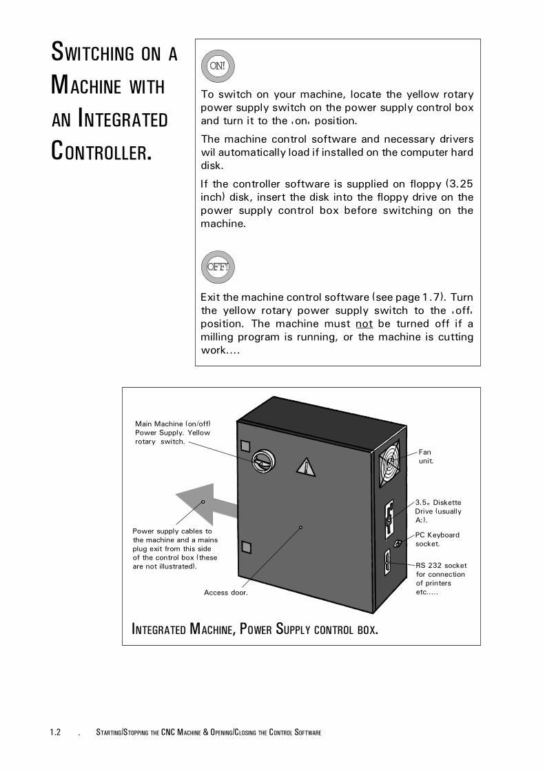
To switch on your machine, locate the yellow rotarypower supply switch on the power supply control boxand turn it to the 'on' position.
The machine control software and necessary driverswil automatically load if installed on the computer harddisk.
If the controller software is supplied on floppy (3.25inch) disk, insert the disk into the floppy drive on thepower supply control box before switching on themachine.
Exit the machine control software (see page 1.7). Turnthe yellow rotary power supply switch to the 'off'position. The machine must not be turned off if amilling program is running, or the machine is cuttingwork....
SWITCHING ON AMACHINE WITH
AN INTEGRATED
CONTROLLER.
3.5" DisketteDrive (usuallyA:).
RS 232 socketfor connectionof printersetc.....
PC Keyboardsocket.
Fanunit.
INTEGRATED MACHINE, POWER SUPPLY CONTROL BOX.
Main Machine (on/off)Power Supply. Yellowrotary switch.
Power supply cables tothe machine and a mainsplug exit from this sideof the control box (theseare not illustrated).
Access door.

1.3STARTING/STOPPING THE CNC MACHINE & OPENING/CLOSING THE CONTROL SOFTWARE -
A pc operated machine has 3 main components:
1) The pc (personal computer) itself, with an attachedDenford Desktop Tutor.
2) The CNC milling machine.
3) The machine power supply unit.
The pc and CNC milling machine are linked togetherso the computer controls the operation of the machinevia the Desktop Tutor.The Power Supply controls forpc operated machines are sited on free standing metalpower supply cabinets (as illustrated below).
SWITCHING ON
A MACHINE
CONTROLLED
BY A PC.
AN EXAMPLE OF AMACHINE
OPERATED
BY A PC. pc.
Denford DesktopTutor.
Power Supply Controlbox.
Denford Triac pc.

1.4 - STARTING/STOPPING THE CNC MACHINE & OPENING/CLOSING THE CONTROL SOFTWARE
To switch on your machine, locate the yellow rotarypower supply switch and turn it to the 'on' position.To load the machine control software, please refer tothe next pages.
.
Exit the machine control software (see page 1.7). Turnthe yellow rotary power supply switch to the 'off'position. The machine must not be turned off if amilling program is running, or the machine is cuttingwork....
SWITCHING ON
A MACHINE
CONTROLLED
BY A PC.
Main Machine (on/off) Power Supply.Yellow rotaryswitch.
Fan unit.
MainsPlug.
Access door.
PC OPERATED MACHINE, POWER SUPPLY CONTROL BOX.
Powersupplycables.
RS 232socket forconnectionof printersetc.....

1.5STARTING/STOPPING THE CNC MACHINE & OPENING/CLOSING THE CONTROL SOFTWARE -
To load the machine control software from your pchard disk, switch on your pc and exit, if necessary, tothe 'DOS' prompt.
The directory in which the software is held and theapplication start-up filename, will depend on the typeof machine used. Please choose the correct directoryand start-up filename from the list shown below....
Machine. Directory. Start-up filename.
Micromill /DENFORD FANUCSMD
Novamill /NOVAMILL FANUCMD
Triac PC /TRIACPC FANUCMD
Please Note - the directories and filenames shownabove are only applicable if the defaults are used wheninstalling the software.
To start the machine control software, type thefollowing at the 'DOS' prompt:
C:\Directory
(where 'C:' is the drive where the software has beeninstalled and 'Directory' is the text chosen from thelist shown above)
Press the [ENTER] / [RETURN] key on the pc keyboard.
Next, type in the 'Start-up filename' chosen from thelist above
Press the [ENTER] / [RETURN] key on the pc keyboard.
The machine control software will now load.
On machines operated with a Desktop Tutor, the pckeyboard is disabled during software use.
PC CONTROLLED
MACHINES -LOADING THE
CONTROL
SOFTWARE FROM
A HARD DISK.

1.6 - STARTING/STOPPING THE CNC MACHINE & OPENING/CLOSING THE CONTROL SOFTWARE
To load the machine controlling software from a floppy(3.25 inch) disk, switch on your pc and exit, ifnecessary, to the 'DOS' prompt.
The application start-up filename will depend on thetype of machine used. Please choose the start-upfilename from the list shown below....
Machine. Start-up filename.
Micromill FANUCSMD
Novamill FANUCMD
Triac PC FANUCMD
To start the machine controlling software, type thefollowing at the 'DOS' prompt:
A:\Start-up filename
(where 'A:' is the floppy (3.25 inch) disk drive and'Start-up filename' is the text chosen from the listabove).
Press the [ENTER] / [RETURN] key on the pc keyboard.
The machine controlling software will now load.
On machines operated with a Desktop Tutor, the pckeyboard is disabled during software use.
PC CONTROLLED
MACHINES -LOADING THE
CONTROL
SOFTWARE FROM
A FLOPPY DISK.

1.7STARTING/STOPPING THE CNC MACHINE & OPENING/CLOSING THE CONTROL SOFTWARE -
CLOSING THE
CONTROL
SOFTWARE.
Select the Main Menu by pressing the [F10] key.
Press the [PAGE DOWN] key to highlight 'Quit', thenpress the [EOB] key to close the control software.
Desktop Tutor Keys Helpbox.The following keys are used in this section:[F10], [PAGE DOWN], [N], [Y], [EOB]
Tutor keypad.
When the Quit option is selected a message may bedisplayed, asking whether the current program beingused needs to be saved.
If this program does not need to be saved, press the[N] key.
If this program does need to be saved, press the [Y]key. Enter the filename (only number characters canbe used with the Desktop Tutor) and press [EOB] tosave the program on the currently selected drive.

1.8 - STARTING/STOPPING THE CNC MACHINE & OPENING/CLOSING THE CONTROL SOFTWARE
CONTROL
SOFTWARE
- MAIN MENU.
Keys Helpbox.The following keys are used in this section:[F10][CURSOR ARROWS][EOB], [RESET]
The Main Menu navigates around the most commonlyused options of the control software.
Select the Main Menu by pressing the [F10] key. Toselect one of the ten options available, highlight therequired option using the [CURSOR ARROWS] keysand press the [EOB] key to confirm this choice.Unwanted menus can be removed by pressing the[RESET] key.
Tutor keypad.

1.9STARTING/STOPPING THE CNC MACHINE & OPENING/CLOSING THE CONTROL SOFTWARE -
CONTROL
SOFTWARE
- MAIN MENU.
The Main Menu contains ten options:
1) Edit Only. This option will display the full screenCNC File Editor with 241 characters sidewaysscrolling facility. The CNC File can be alteredusing this option. Simulation is not available fromthis section but pressing the [F9] key will run asyntax check on the CNC Code.
2) Edit and Simulate. This option will display the CNCFile Editor, Simulation graphics and Tutorialwindows as a split screen. If the CNC line is longerthan the Editor window, a sideways scrollingfacility will be offered. During CNC File editing, agraphical Simulation can be started at any time.When this Simulation has ben completed, thecursor will return to its last position in the CNCFile Editor. The CNC File can be altered using thisoption.
3) Simulate Only. This option will display the CNCFile in full screen graphical format only. TheTutorial window is still displayed at the bottomof the screen. If an error occurs during a CNC Fileexecution, the Edit and Simulate Mode will beautomatically selected and the error codehighlighted. The CNC File cannot be alteredusing this option.
4) Link to Controller. This option allows a CNC Fileto be downfed or loaded from an external FANUCcontroller.
5) CNC Files. This option gives access to a sub-menuallowing CNC Files to be loaded, created, saved,deleted and the drive directories changed.
6) Print. This option will print the currently loadedCNC File in various formats.
7) Remote Link. This option gives access to a sub-menu allowing the machine controller to be linkedto an external device (such as a paper tape punchetc) for CNC File transfer.
8) Settings. This option gives access to a sub-menuallowing many of the options listed above to becustomised and configured.
9) Utilities. This option will allow access to othersoftware products running through DOS.
10) Quit. This option will exit the machine controlsoftware and returns to DOS.

1.10 - STARTING/STOPPING THE CNC MACHINE & OPENING/CLOSING THE CONTROL SOFTWARE

2.1AUTOMATIC SEARCH FOR THE MACHINE DATUM POINT -
AUTOMATIC
SEARCH FOR
THE MACHINE
DATUM POINT.
It is necessary to home the machine whenever it isswitched on, to find the machine datum point - this isused as a zero reference for describing otherco-ordinates on the machine.
The machine datum zero reference point (co-ordinatesX=0, Y=0, Z=0) is the front, left, lower corner of animaginary block placed on the table. The block itselfrepresents the largest possible size of workpiece themiller could manage to machine.
The machine datum point is used when taking anymeasurements from future co-ordinates we load orprogram. This is fine, if the start co-ordinates of ourwork coincide with the machine datum zero referencepoint. If not, this point must be moved - see section4.3 "Setting the Tool Offset of the Machine".
LOCATING THE
MACHINE DATUM
ZERO REFERENCE
POINT.
Maximum machiningsize shown by'imaginary' block.
Front, left, lower corner of theblock is the machine datum zeroreference point, with theco-ordinates X=0, Y=0, Z=0.
2.2 - AUTOMATIC SEARCH FOR THE MACHINE DATUM POINT
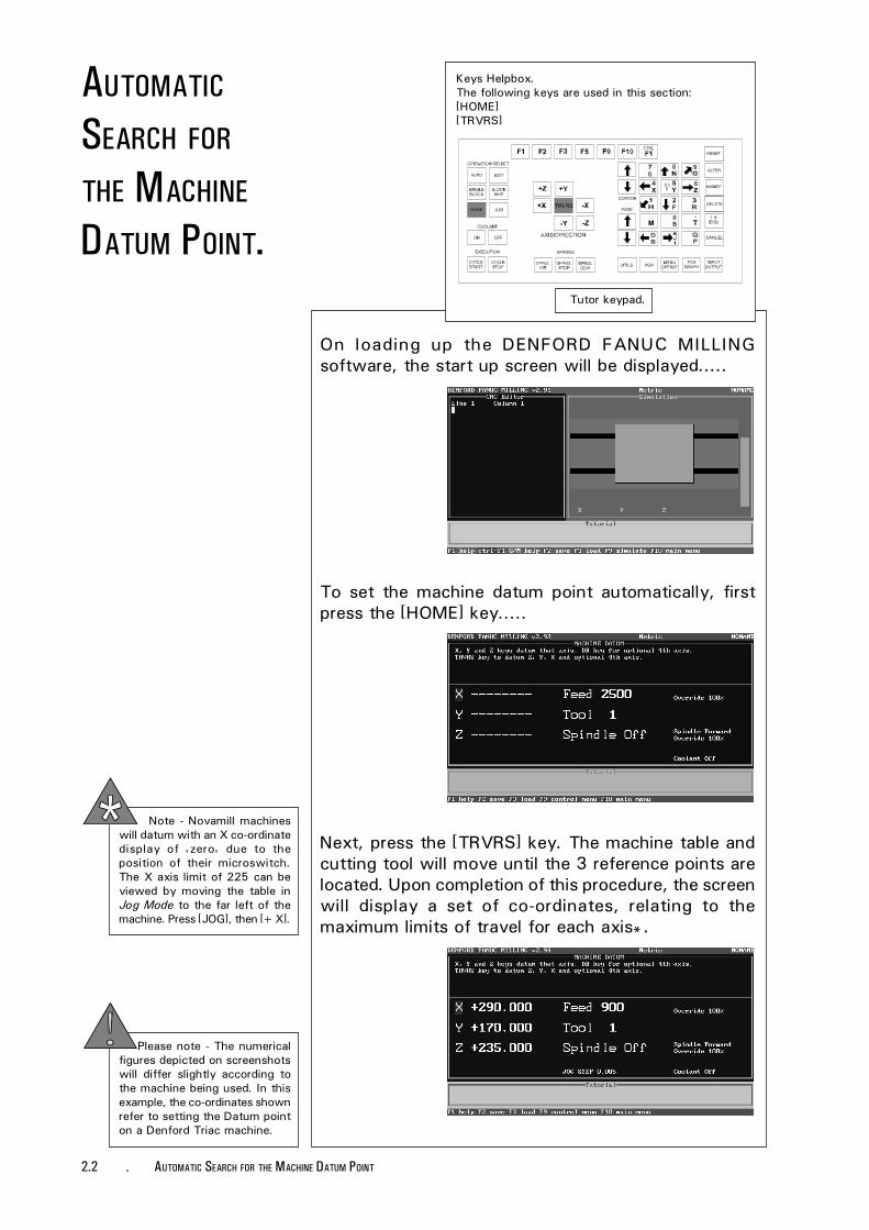
Keys Helpbox.The following keys are used in this section:[HOME][TRVRS]
Tutor keypad.
On loading up the DENFORD FANUC MILLINGsoftware, the start up screen will be displayed.....
To set the machine datum point automatically, firstpress the [HOME] key.....
Next, press the [TRVRS] key. The machine table andcutting tool will move until the 3 reference points arelocated. Upon completion of this procedure, the screenwill display a set of co-ordinates, relating to themaximum limits of travel for each axis*.
Please note - The numericalfigures depicted on screenshotswill differ slightly according tothe machine being used. In thisexample, the co-ordinates shownrefer to setting the Datum pointon a Denford Triac machine.
Note - Novamill machineswill datum with an X co-ordinatedisplay of 'zero' due to theposition of their microswitch.The X axis limit of 225 can beviewed by moving the table inJog Mode to the far left of themachine. Press [JOG], then [+X].
AUTOMATIC
SEARCH FOR
THE MACHINE
DATUM POINT.
3.1SETTING THE DATUM PLATE -
SETTING THE
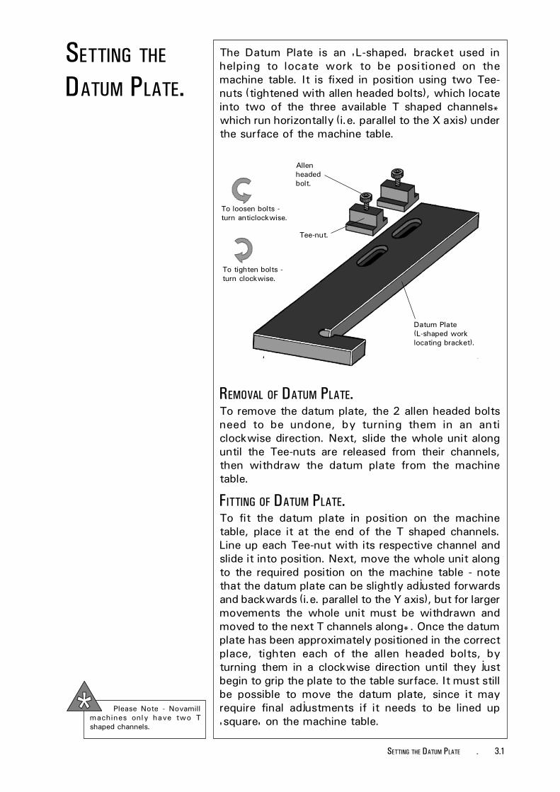
DATUM PLATE.The Datum Plate is an 'L-shaped' bracket used inhelping to locate work to be positioned on themachine table. It is fixed in position using two Tee-nuts (tightened with allen headed bolts), which locateinto two of the three available T shaped channels*which run horizontally (i.e. parallel to the X axis) underthe surface of the machine table.
Datum Plate(L-shaped worklocating bracket).
Allenheadedbolt.
Tee-nut.
To loosen bolts -turn anticlockwise.
To tighten bolts -turn clockwise.
REMOVAL OF DATUM PLATE.To remove the datum plate, the 2 allen headed boltsneed to be undone, by turning them in an anticlockwise direction. Next, slide the whole unit alonguntil the Tee-nuts are released from their channels,then withdraw the datum plate from the machinetable.
FITTING OF DATUM PLATE.To fit the datum plate in position on the machinetable, place it at the end of the T shaped channels.Line up each Tee-nut with its respective channel andslide it into position. Next, move the whole unit alongto the required position on the machine table - notethat the datum plate can be slightly adjusted forwardsand backwards (i.e. parallel to the Y axis), but for largermovements the whole unit must be withdrawn andmoved to the next T channels along*. Once the datumplate has been approximately positioned in the correctplace, tighten each of the allen headed bolts, byturning them in a clockwise direction until they justbegin to grip the plate to the table surface. It must stillbe possible to move the datum plate, since it mayrequire final adjustments if it needs to be lined up'square' on the machine table.
Please Note - Novamillmachines only have two Tshaped channels.

3.2 - SETTING THE DATUM PLATE
The following diagrams illustrate a number ofmethods for making final adjustments to the datumplate. Each method varies according to the accuracyrequired, when the datum plate needs to be positioned'square' with respect to the machine table (i.e. theedges of the datum plate run exactly parallel with the3 machine axes).
To obtain a better degree of accuracy, use an engineers square lined up against thefront edge of the machine table. Adjust the datum plate so it touches the engineerssquare and tighten the allen headed bolts. This method has the added advantage ofallowing the datum plate to be fixed further 'into' the machine table (i.e. anywhereon the machine table running parallel with the Y axis).
Datum Plate.
EngineersSquare.
MachineTable.
This method is useful if the front face of thedatum plate can be positioned exactly levelwith the front edge of the machine table. Usethe 'true' flat face (i.e. accurately level andstraight) of a section of material, such as apiece of flat steel bar. Press the steel bar firmlyagainst the front edge of the table and adjustthe datum plate so its front face also touchesthe surface of the steel bar. Tighten the allenheaded bolts. Note that although this methodis quick, it is also fairly inaccurate.
Flat piece of steel bar.
Datum Plate.
Machine Table.
1
2

3.3SETTING THE DATUM PLATE -
Set up the machine so a pointer is held in place of the cutting tool (the [T]key will change tools on an automatic tool changer). Align the pointingtool so it is positioned slightly above one of the 2 edges of the datumplate, which run parallel with the Y axis. Use the [+X], [-X], [+Y], [-Y],[+Z] and [-Z] keys to move the pointing tool, with the Jog Mode set toread 'continuous' on screen (this can be selected using the [JOG] key).This can only be done with the guard closed, since the axes will onlymove in Incremental Jog Mode with the guard open.
Be careful not to hit the edge of the datum plate with the pointer whenmanoeuvring it into position above the chosen edge.
3
Datum Plate.
PointerTool.
MachineTable.
Start with the pointer near the back of the datum plate edge you have chosen. Usethe [-Y] key to move the pointer towards the front of the datum plate, checkingthat the tip of the pointer is still lined up exactly over the edge you have chosen. Ifthe pointer does not line up, then manually adjust the position of the datum plateuntil it does. Keep repeating these steps, moving the pointer forwards andbackwards, along the datum plate edge, until a suitable degree of accuracy hasbeen obtained.
For a final check, the pointer can be moved above and along one of the datumplate edges which run parallel to the X axis. Finally, tighten the allen headed boltsto fix the datum plate firmly in place.

3.4 - SETTING THE DATUM PLATE
Set up the machine so a dial gauge is held in place of the cutting tool (the [T] keywill change tools on an automatic tool changer). Align the dial gauge so it ispositioned along one of the 2 sides of the datum plate, which run parallel with theY axis. Use the [+X], [-X], [+Y], [-Y], [+Z] and [-Z] keys to move the dial gauge,with the Jog Mode set to read 'continuous' on screen (this can be selected usingthe [JOG] key).
Start with the dial gauge near the back of the datum plate edge you have chosen.Use the [-Y] key to move the dial gauge towards the front of the datum plate,checking that the values indicated on the dial gauge do not alter. If the values doalter, then manually adjust the position of the datum plate until the values areconstant. Keep repeating these steps, moving the dial gauge forwards and back-wards along the datum plate edge, using the [+Y] and [-Y] keys, until a suitabledegree of accuracy has been obtained. Finally, tighten the allen headed bolts to fixthe datum plate firmly in place.
4
Dial gauge.
Machine Table.
Datum Plate.

3.5CAMPING THE WORKPIECE -
CLAMPING THE
WORK PIECE -
Miteebiteclamp.
TemporaryMDF bed.
Machinetable.
Datum plate.
USING MITEEBITE
CLAMPS.
The actual workpiece, such as a sheet of plastic,would be held in place on the temporary MDF bedusing double sided tape.
Miteebite clamp - shown in'closed' position.
Miteebite clamps are a quick and versatile method ofsecuring most pieces of work to the machine table. Inthe example shown below, a temporary MDF bed isused as a 'sub machine table'. This bed is clampeddown and used as a safety measure to preventdamage occurring to the machine table itself, should aproblem occur when milling.

3.6 - CAMPING THE WORKPIECE
HOW DOES AMITEEBITE CLAMP
WORK?Hexagonwasher.
Grub screw passesthrough the base ofthe Tee-nut.
To loosen grubscrewturn anticlockwise.
To tighten grubscrewturn clockwise.
Tee-nut.
Bolt - both the headand the allen keyholes are machinedslightly 'off centre'.
The base of the Miteebite clamp consists of a Tee-nut,with 2 threaded holes passing right through itssection from top to bottom.
One of these threaded holes contains a grubscrew.When this is tightened, the base of the grubscrewpushes against the surface of the T channel in which ithas been placed, thus securing the Tee-nut inposition.
The other threaded hole contains a bolt which has itshead and allen key hole machined slightly 'off centre'.A hexagon washer spins freely around this bolt head.The bolt behaves in a similar way to a cam whenrotated. If the allen key hole is facing away from thegrubscrew, then the hexagon washer is 'slack' againstthe work (i.e. the miteebite is 'open'). If the bolt isthen turned through 180 degrees so that the allen keyhole is now facing towards the grubscrew, then thehexagon washer will be 'tight' against the work (i.e.the miteebite is 'closed').
Continual turning of the bolt is unnecessary, since thefull range of movement for the hexagon washer iscovered in a single 360 degree rotation of the bolt. Inthis respect, the hexagon washer will not tightenfurther if the bolt is continually turned clockwise.

3.7CAMPING THE WORKPIECE -
CLAMPING A PIECE
OF WORK USING
THE MITEEBITE
CLAMPS.Set the Datum Plate into position, as described insection 3.1, then place the workpiece onto themachine table, so it is located correctly against thedatum plate.
Next, position the miteebites into their respective Tchannels and slide them along until they touch thetemporary MDF bed. Ensure that it is one of the sixflat sides of the hexagon washers which press againstthe workpiece, not one of their points.
Note that the hexagon washers should be positionedat this stage so they are 'open' (i.e. the off-centreallen key holes on the bolts should be facing awayfrom the grubscrews) as shown in the illustrationdirectly to the left.....
The example used in this sectionis the temporary MDF bed witha sheet of plastic retained usingdouble sided tape.
Hexagon washer setin closed position.
Now that the miteebites have been set, the temporaryMDF bed can be continually withdrawn from themachine table, then replaced, always to the sameposition. This is an advantage for jobs involving therepeat milling of pieces of work, such as a small'production run' or a 'college class/group project'.
Now tighten the grubscrews in each miteebite to lockthem firmly in position. At this stage, it should still bepossible to remove the temporary MDF bed.
Remember, the grubscrews only lock the miteebites inposition on the machine table - it is the hexagonwashers which actually lock the workpiece inposition.
To finally lock the workpiece firmly in place, turn thebolts with the off-centre allen key holes 180 degreesso the hexagon washers are in the 'closed' position(i.e. the off-centre allen key holes on the bolts shouldnow be facing towards the grubscrews) as shown inthe illustration directly to the left.....
Hexagon washer setin open position.

3.8 - CAMPING THE WORKPIECE

4.1CHANGING THE TOOL -
CHANGING THE
TOOL WITH AN
AUTOMATIC TOOL
CHANGER.
Keys Helpbox.The following keys are used in this section:[T], [DELETE], [JOG][NUMBERS] - these keys are not highlighted.
Tutor keypad.
Note there should never bea cutting tool in the carouselpocket directly facing thespindle.
The automatic tool changer is used to transferdifferent tool holders between the head of themachine and the carousel (at the back of the machine)where they are stored when not in use. Each slot onthe carousel is assigned a 'number'. The tool holderscan also be referred to by these numbers, if the theyare always kept in the same carousel slot, with thesame tool profile present in the holder.
To change to a different tool number, first check themachine is set in Jog Mode (selected by pressing the[JOG] key). Next, press the [T] key to obtain the Toolnumber prompt, then type in the number of the toolyou wish to change to, using the [NUMBER] keys. Anyincorrect numbers typed in can be removed bypressing the [DELETE] key. Press the [EOB] key toconfirm this tool number. The tool numbers will nowbe changed automatically on the screen as thecarousel changes the tool holders.

4.2 - CHANGING THE TOOL
CHANGING THE
TOOL MANUALLY.
Keys Helpbox.The following keys are used in this section:[T], [DELETE], [JOG][NUMBERS] - these keys are not highlighted.
If the machine is not equipped with an automatic toolchanger, then each tool needs to be changedmanually.
The software commands and prompts remain the sameas changing the tool, automatically. Check themachine is set in Jog Mode (selected by pressing the[JOG] key), press the [T] key to obtain the Tool numberscreen prompt, then enter the number of the tool youwish to change to and press the [EOB] key to confirmthis operation is correct.
Tutor keypad.
Note that when a programusing more than one tool is runin future, the software willprompt you to manually changetools before continuing.
Removing a Tool manually.
Quick-releasepin.
Quick-release collar.
Turn clockwiseto loosen.
Tool.
Refitting a Tool manually.
Quick-releasepin.
Locating slots.
Tool.
Quick-releasecollar.
Driving Dogs.
To physically remove a tool from the machine,grip the tool holder quick-release collar, so thatthe quick-release pin in it is fully depressed.Hold the tool itself still and rotate thequick-release collar clockwise until it stops.Remove the tool whilst keeping the quick-release pin still depressed - this prevents thequick-release mechanism from closing.
To refit, align the two locating slots of the toolwith the two driving dogs on the quick-releasecollar. Push the tool up into the holder. Thequick-release mechanism should now springclosed and grip the 'new' tool securely.
Finally, press the [EOB] key to confirm that thetool change is now complete.
Note - the [EOB] key needs to be pressed twicefor manual tool changes, once to confirm therequest for a tool change operation and asecond time to confirm the tool holder hasphysically been changed.

4.3SETTING THE TOOL OFFSETS -
SETTING THE
TOOL OFFSETS
- INTRODUCTION.
Quite often, the workpiece is much smaller than the'imaginary block' used in setting the machine datumpoint (see section 2.1). For example, a typical piece ofwork could be a small sheet of plastic fixed to atemporary MDF bed with double sided tape (toprevent damage occurring to the table whenmachining) as shown in the diagram below. Due to itssize, the work is usually clamped somewhere in themiddle of the table.
The miller, however, will still recognise its originalmachine datum point and take all its measurementsfrom here. Therefore, we must move this machinedatum point to coincide exactly with the 'new' start-ing co-ordinates of our piece of work - this 'new'datum is called the 'Work Datum point'. It must alsotake account of all the different types of tools we wishto use.
Miteebiteclamp.
Workdatumpoint.
TemporaryMDF bed.
The surface of the MDF is the level at which allthe (Z co-ordinate)Tool Offsets are set.
Datumplate.
Location of 'original' machinedatum zero reference point.
The plastic sheet is fixed to thetemporary MDF bed using
double sided tape.
Example workpiece -plastic sheet.
Miteebiteclamp.
LOCATION OF THE WORK DATUM POINT
AND THE LEVEL FOR TOOL OFFSETS.Machinetable.
This operation consists of two stages :
1) Programming a Work Datum point for the X and Yaxes only.
2) Programming the Tool Offsets for the Z axis (thistakes into account the different types of tools, sincethey all differ in length).
This operation is sometimesreferred to as 'setting thetool offsets'.

4.4 - SETTING THE TOOL OFFSETS
SETTING THE
WORK DATUM
X AND YCO-ORDINATES.
Instructions refer to setting up the X and Yco-ordinates for the example workpiece described onthe previous page - 'Setting Tool Offsets -Introduction' (Section 4.3).
Please note -The co-ordinate values depictedon screenshots are used forillustrative purposes only.
Keys Helpbox.The following keys are used in this section:[JOG]
Tutor keypad.1.
WARNING - BEFORE BEGINNING TO SET THE X AND YOFFSETS, ENSURE THE X AND Y VALUES IN THE TOOL
OFFSETS TABLE ARE SET TO Ø (SEE PAGE 4.17) .
Front, left,corner of mdf.
To set the X and Y co-ordinates, the position of thefront, left, corner of the temporary MDF bed needs tobe found.
Select the Jog Mode by pressing the [JOG] key. Whenin Jog Mode, the miller can be controlled manually.The screen will display the X, Y and Z co-ordinates,the tool selected (this should be tool 1) and thespindle action (this should be off).
Before moving the table or head in any direction, youneed to set the movement to 'continuous' (ie, thetable or head will move continuously, so long as oneof the movement keys is being pressed). To do this,press the [JOG] key again until the screen shows thewords 'continuous' in the lower area of the display.

4.5SETTING THE TOOL OFFSETS -
Keys Helpbox.The following keys are used in this section:[+X] & [-X], [+Y] & [-Y], [+Z] & [-Z], [TRVRS]
Tutor keypad.
Using the blue [+X], [-X], [+Y], [-Y], [+Z] and [-Z]keys, move the cutter so it is positioned fairly close toanywhere on the MDFs upper surface, but nottouching.
Pressing the [TRVRS.] key at the same time willincrease this rate of movement.
You should notice that as the table or head are moved,the X, Y or Z co-ordinates displayed on the screen willchange. These numbers are the co-ordinates of thecutting tool tip, relative to its previously set datumpoint.
2.
The machineshould look likethis at the end ofthis section.
Cutting tooldirectly over mdfsurface.
[+X] - Moves the table left.[-X] - Moves the table right.[+Y] - Moves the table towards the
front.[-Y] - Moves the table towards the
back.[+Z] - Moves the cutter up.[-Z] - Moves the cutter down.
SETTING THE
WORK DATUM
X AND YCO-ORDINATES.
4.6 - SETTING THE TOOL OFFSETS
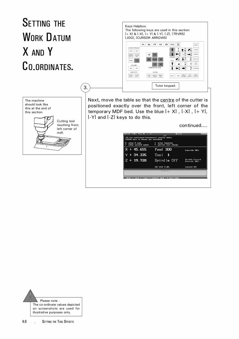
Next, move the table so that the centre of the cutter ispositioned exactly over the front, left corner of thetemporary MDF bed. Use the blue [+X] , [-X] , [+Y],[-Y] and [-Z] keys to do this.
continued....
Keys Helpbox.The following keys are used in this section:[+X] & [-X], [+Y] & [-Y], [-Z], [TRVRS][JOG], [CURSOR ARROWS]
Tutor keypad.
The machineshould look likethis at the end ofthis section.
3.
Cutting tooltouching front,left corner ofmdf.
Please note -The co-ordinate values depictedon screenshots are used forillustrative purposes only.
SETTING THE
WORK DATUM
X AND YCO-ORDINATES.

4.7SETTING THE TOOL OFFSETS -
3.
Note - as a safety featurethe machine will not operate inJog Mode continuous with theguard open, only in the lastsetting for Jog steps.
SETTING THE
WORK DATUM
X AND YCO-ORDINATES.
[+X] - Moves the table left.[-X] - Moves the table right.[+Y] - Moves the table towards the
front.[-Y] - Moves the table towards the
back.[+Z] - Moves the cutter up.[-Z] - Moves the cutter down.
continued....
When you are fairly close to this point the [JOG] keycan be used to switch from 'continuous' to a moreaccurate degree of adjustment using steppedmovements (ie, the table or head will move a setamount each time you press a movement key).
The size of movement will be displayed, for example'JOG STEP 0.005' is a movement of 0.005mm everytime you press a movement key.
Depending on the accuracy of the movement required,this can be selected using the blue [CURSOR ARROWS]keys. Jog steps can be selected between a movementof 0.005mm minimum to 5mm maximum.
When fine adjustments are being made, open themachine guard to check the accuracy of the cutterposition.

4.8 - SETTING THE TOOL OFFSETS
Please note -The co-ordinate values depictedon screenshots are used forillustrative purposes only.
SETTING THE
WORK DATUM
X AND YCO-ORDINATES.
Keys Helpbox.The following keys are used in this section:[NUMBERS], [X], [Y][CURSOR ARROWS][EOB], [RESET], [DELETE]
Tutor keypad.5.
Keys Helpbox.The following keys are used in this section:[MENU OFFSET][CURSOR ARROWS][EOB]
Tutor keypad.
Select the Offset Control Menu by pressing the [MENUOFFSET] key and highlight the 'Edit offsets' optionusing the blue [CURSOR ARROWS] keys. Select thiscommand by pressing the [EOB] key (this is the End OfBlock, or enter key).
4.
From the list of Offsets shown, highlight the 'X co-ordinate offset' using the blue [CURSOR ARROWS]keys. To enter the new X value, press the [X] key tomove the screen cursor across to where it reads '0'.Type in the new value using the [NUMBERS] keys; usethe [DELETE] key to remove any incorrect characters.
continued....

4.9SETTING THE TOOL OFFSETS -
Press the [EOB] key to confirm this new figure. The Xvalue you want to copy is displayed to the left of theoffset screen.
Repeat the same steps for the 'Y co-ordinate offset'(pressing the [Y] key to move the screen cursor acrossto where the Y value reads '0').
Keys Helpbox.The following keys are used in this section:[NUMBERS], [X], [Y][CURSOR ARROWS][EOB], [RESET], [DELETE]
Tutor keypad.
To check if this has registered correctly, press the[RESET] key and look at the main screen to see if theX and Y co-ordinates have returned to zero (ie, thecutter recognises this point as its new datum for Xand Y).
5.
Please note -Tool Radius values (R) are onlyrequired for CNC Files usingcutter compensation codes (G41and G42). They do not requiresetting for a machine using CNCFiles generated with MillCAMDesigner.
SETTING THE
WORK DATUM
X AND YCO-ORDINATES.
[+X] - Moves the table left.[-X] - Moves the table right.[+Y] - Moves the table towards the
front.[-Y] - Moves the table towards the
back.[+Z] - Moves the cutter up.[-Z] - Moves the cutter down.
Please note -Clear (zero) any previouslystored offsets, before enteringany new values.

4.10 - SETTING THE TOOL OFFSETS
SETTING THE
TOOL OFFSET ZCO-ORDINATES.
Instructions refer to setting up the Z co-ordinate forthe example workpiece described in section 4.3 -'Setting Tool Offsets - Introduction'.
To set the Tool Offset Z co-ordinate, the cutter needsto be placed so it is just touching the surface of thetemporary MDF bed.
When this new Z figure is combined with the X and Yfigures previously entered, the co-ordinates found willbe our new datum point but only for the tool that iscurrently selected (at the moment this should be tool1). This process must be repeated for each tool wewish to use on the workpiece.
Please note -The co-ordinate values depictedon screenshots are used forillustrative purposes only.
WARNING - BEFORE BEGINNING TO SET THE ZOFFSETS, ENSURE THE Z VALUES IN THE TOOL
OFFSETS TABLE ARE SET TO Ø (SEE PAGE 4.17) .
Keys Helpbox.The following keys are used in this section:[JOG], [+Z], [TRVRS][+X] & [-X][+Y] & [-Y]
Tutor keypad.
Select the Jog Mode by pressing the [JOG] key andcheck that it is set to 'continuous'. Before moving thetable in any direction, raise the head using the [+Z]key so that it is comfortably above any surfaces itcould hit when moving across.
Now move the table so that the cutter is positionedsomewhere over the surface of the temporary MDFbed using the [+X] , [-X] , [+Y] and [-Y] keys.
1.
The machineshould look likethis at the end ofthis section.
Cutting tooldirectly overmdf surface.

4.11SETTING THE TOOL OFFSETS -
Keys Helpbox.The following keys are used in this section:[JOG][+Z] & [-Z][TRVRS]
Tutor keypad.
Using the [+Z] and [-Z] keys, make the tip of the cut-ter just touch the top surface of the bed.
Remember that the Jog Mode can be changed tostepped movements for greater accuracy, once the tipis quite close to the surface.
As the cutter approaches the surface of the bed, spinit slowly by hand to help check when it makescontact.
Note - as a safety featurethe machine will not operate inJog Mode continuous with theguard open, only in the last set-ting for Jog steps.
2.
The machineshould look likethis at the end ofthis section.
Cutting tooltouching mdfsurface.
SETTING THE
TOOL OFFSET ZCO-ORDINATES.
[+X] - Moves the table left.[-X] - Moves the table right.[+Y] - Moves the table towards the
front.[-Y] - Moves the table towards the
back.[+Z] - Moves the cutter up.[-Z] - Moves the cutter down.

4.12 - SETTING THE TOOL OFFSETS
Please note -The co-ordinate values depictedon screenshots are used forillustrative purposes only.
Next, select the Offset Control Menu by pressing the[MENU OFFSET] key, highlight the 'Edit offsets'option and select it by pressing the [EOB] key. Fromthe list of Offsets shown, highlight the 'tool 1 offset'using the [CURSOR ARROWS] keys (see screenshotbelow).
Note - do not highlight the 'Z co-ordinate offset' bymistake! To move the screen cursor across to where itreads 'Z0', press the [Z] key.
Keys Helpbox.The following keys are used in this section:[MENU OFFSET][Z], [CURSOR ARROWS][EOB]
Tutor keypad.3.
SETTING THE
TOOL OFFSET ZCO-ORDINATES.
Please note -Clear (zero) any previouslystored offsets, before enteringany new values.

4.13SETTING THE TOOL OFFSETS -
Keys Helpbox.The following keys are used in this section:[NUMBERS][EOB][RESET], [DELETE]
Enter the new Z value, using the [NUMBERS] keys;use the [DELETE] key to remove any incorrectcharacters. The Z value you want to copy is displayedto the left of the offset screen. Press the [EOB] key toconfirm this value.
To check if this has registered correctly, press the[RESET] key and look at the main screen to see if theZ co-ordinate has returned to zero (ie, the cutterrecognises this point as its tool offset for Z, whenusing tool 1).
4. Tutor keypad.
Please note -Tool Radius values (R) are onlyrequired for CNC Files usingcutter compensation codes (G41and G42). They do not requiresetting for a machine using CNCFiles generated with MillCAMDesigner.
SETTING THE
TOOL OFFSET ZCO-ORDINATES.
[+X] - Moves the table left.[-X] - Moves the table right.[+Y] - Moves the table towards the
front.[-Y] - Moves the table towards the
back.[+Z] - Moves the cutter up.[-Z] - Moves the cutter down.

4.14 - SETTING THE TOOL OFFSETS
5.
Each cutting tool is a different length, so the Z tooloffset co-ordinates you have entered for tool 1 willnot necessarily be correct when using other toolnumbers.
Therefore, the 'Z co-ordinate Tool Offsets' stage mustbe carried out and the values entered, for each toolyou wish to use when machining.
For example, if you want to use tool 3, you wouldhave to change from your current tool (number 1) totool 3. Then, you would position this cutter so ittouched the surface of the bed again, select 'Editoffsets' and transfer the values for this cutter into thetool 3 offset menu.
TOOL SELECTIONS.
Please note -The co-ordinate values depictedon screenshots are used forillustrative purposes only.
SETTING A'GLOBAL' ZVALUE FOR WORK
MATERIAL
THICKNESS.
The plastic sheet is fixed to thetemporary MDF bed using double
sided tape.
Example workpiece -plastic sheet.
Now that the Tool Offsets have been set to coincidewith the surface of the temporary MDF bed, theworkpiece is fixed into position (in this example it is asheet of plastic - refer to the diagram opposite). If themiller starts cutting it will take all its Z co-ordinatemeasurements from the surface of the temporary MDFbed (i.e. the Z Tool Offsets).
Due to the way the programs are written, we requirethis Z co-ordinate measurement to be taken from thesurface of the work itself, otherwise the miller willstart cutting into the temporary MDF bed and not ourworkpiece.
Each Z co-ordinate for each tool must therefore bemoved up, the distance moved up equating to thethickness of our work material. Rather than programthis value individually for each tool as desribed whensetting the Z co-ordinate Tool Offsets, we canprogram a 'global' Z value which will be applied toeach tool automatically.

4.15SETTING THE TOOL OFFSETS -
Keys Helpbox.The following keys are used in this section:[MENU OFFSET], [CURSOR ARROWS][EOB], [Z], [DELETE], [NUMBERS] - not highlighted.
Tutor keypad.
Select the Offset Control Menu by pressing the [MENUOFFSET] key, highlight the 'Edit Offsets' option usingthe blue [CURSOR ARROWS] keys and press the [EOB]key.
From the list of offsets shown highlight the 'Z'co-ordinate (not any of the Tool number co-ordinates!)and press the [Z] key to move the cursor across towhere it reads '0'.
Enter the 'global' Z value - this should be thethickness of your work material. Use the [DELETE] keyto remove any incorrect characters.
Finally, press [EOB] to confirm this 'global' Z value.
SETTING A'GLOBAL' ZVALUE FOR WORK
MATERIAL
THICKNESS.
[+X] - Moves the table left.[-X] - Moves the table right.[+Y] - Moves the table towards the
front.[-Y] - Moves the table towards the
back.[+Z] - Moves the cutter up.[-Z] - Moves the cutter down.
To check if this has registered correctly, press the[RESET] key and look at the main screen, the Zco-ordinate value will reduce by the value entered intothe global Z offset.

4.16 - SETTING THE TOOL OFFSETS
The tool radius, 'R',may be typed into the collection oftool offsets. The radius or diameter value is usuallystamped on the cutting tool.
The software will assign a default value of 2.5 to atool radius.
Tool radius values are required by programs that usethe G41 (Cutter Compensation Left) and G42 (CutterCompensation Right) codes.
They do not need to be set for any CNC Filesgenerated using Denford MillCAM Designer.
To alter the tool radius values, press the [MENUOFFSET] key and use the [CURSOR] keys to highlightthe 'Edit Offsets' option. Press the [EOB] key todisplay the Table of Tool Offsets.
Use the [CURSOR] keys to highlight the tool numberrequired, then press the [R] key to switch the cursorto the 'R' value. Type the tool radius value into thetable using the [NUMBER] keys (any incorrectcharacters can be removed by pressing the [DELETE]key, or use the [ALTER] key to remove the existingvalues), then press the [EOB] key.
Press the [RESET] key to remove the tool offsets tableand any unwanted menus from the screen.
TOOL OFFSETS
- SETTING THE
TOOL RADIUS
VALUE.
Please note -The co-ordinate values depictedon screenshots are used forillustrative purposes only.
Keys Helpbox.The following keys are used in this section:[MENU OFFSET],[CURSOR ARROWS], [EOB][R], [DELETE], [RESET], [ALTER][NUMBERS] - not highlighted
Tool Radius value.
Tutor keypad.
4.17SETTING THE TOOL OFFSETS -
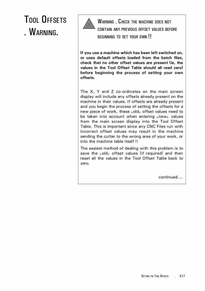
If you use a machine which has been left switched on,or uses default offsets loaded from the batch files,check that no other offset values are present (ie, thevalues in the Tool Offset Table should all read zero)before beginning the process of setting your ownoffsets.
The X, Y and Z co-ordinates on the main screendisplay will include any offsets already present on themachine in their values. If offsets are already presentand you begin the process of setting the offsets for anew piece of work, these "old" offset values need tobe taken into account when entering "new" valuesfrom the main screen display into the Tool OffsetTable. This is important since any CNC Files run withincorrect offset values may result in the machinesending the cutter to the wrong area of your work, orinto the machine table itself !!
The easiest method of dealing with this problem is tosave the "old" offset values (if required) and thenreset all the values in the Tool Offset Table back tozero.
continued....
WARNING - CHECK THE MACHINE DOES NOT
CONTAIN ANY PREVIOUS OFFSET VALUES BEFORE
BEGINNING TO SET YOUR OWN !!
TOOL OFFSETS
- WARNING.

4.18 - SETTING THE TOOL OFFSETS
TOOL OFFSETS
- WARNING.If you suspect that a set of offsets may already bepresent on the machine, follow this procedure :
Press the [MENU OFFSET] key and select 'EditOffsets' followed by [EOB] to display the Tool OffsetsTable.. All the numerical values present in the 'X,Y,Zor Tool No.' sections of the display must read ZERO.If they do not, then change each one.... enteringvalues into the Tool Offset Table is covered in anearlier part of this section. The default Tool Offset Tablescreen is shown below.
When all the values have been set to ZERO, press the[RESET] key. Notice that the main screen co-ordinateswill change indicating that the new offsets (Ø,Ø,Ø)have been applied. Your own set of "new" workoffsets can now be manually entered, safely.
If you regularly use a machine which others haveaccess to, it may save time if you save your own"default" offset file with all the co-ordinates set atZERO.

4.19OFFSET FILES - LOADING AND SAVING -
Please note -The co-ordinate values depictedon screenshots are used forillustrative purposes only.
OFFSET FILES
- CONTROL MENU.
Keys Helpbox.The following keys are used in this section:[MENU OFFSET][CURSOR ARROWS][EOB] & [RESET]
Tutor keypad.
Select the Offset Control Menu by pressing the[MENU OFFSET] key.
The Offset Control Menu contains 4 options:
i) Execute CNC - run the currently loaded CNC Fileon the machine.
ii) Edit Offsets - the Tool Offset Table is displayed,from which individual Offset values can be altered.
iii) Load Offsets - load a collection of Tool Offsets.
iv) Save Offsets - save a collection of Tool Offsets.
Press the [RESET] key to clear any menus.

- OFFSET FILES - LOADING AND SAVING4.20
Please note -The co-ordinate values depictedon screenshots are used forillustrative purposes only.
OFFSET FILES
- EXECUTE CNC.
Keys Helpbox.The following keys are used in this section:[MENU OFFSET][CURSOR ARROWS][EOB] & [RESET]
Tutor keypad.
The 'Execute CNC' command will run any CNC Filecurrently loaded.
To run the currently loaded CNC File, select the OffsetControl Menu by pressing the [MENU OFFSET] key.
From the four choices, highlight the 'Execute CNC'option using the blue [CURSOR ARROWS] keys andpress [EOB].
The machine will switch to Auto Mode and will allowthe user to run the currently loaded CNC File.
If no CNC File is present, the Offset Control Menu willbe removed from the current display.

4.21OFFSET FILES - LOADING AND SAVING -
OFFSET FILES
- EDIT OFFSETS.
Keys Helpbox.The following keys are used in this section:[MENU OFFSET][CURSOR ARROWS][EOB] & [RESET]
Tutor keypad.
The 'Edit Offsets' command will display the ToolOffsets Table.
To edit or view the current collection of tool offsetvalues, select the Offset Control Menu by pressingthe [MENU OFFSET] key.
From the four choices, highlight the 'Edit Offsets'option using the blue [CURSOR ARROWS] keys andpress [EOB].
Press the [RESET] key to clear the screen of anyunwanted menus or information.
The Tool Offset values are displayed; to edit theirvalues, see section 4.3 - "Setting Tool Offsets".
The default Tool Offset Table (ie, no offsets areentered) is shown below.

- OFFSET FILES - LOADING AND SAVING4.22
OFFSET FILES
- LOAD.
Please note -The co-ordinate values depictedon screenshots are used forillustrative purposes only.
Keys Helpbox.The following keys are used in this section:[MENU OFFSET][EOB], [ALTER][CURSOR ARROWS][NUMBERS]
Tutor keypad.
To load a collection of offset values, select the OffsetControl Menu by pressing the [MENU OFFSET] key.From the four choices, highlight the 'Load offsets'option using the blue [CURSOR ARROWS] keys andpress [EOB].
Enter the file name (number) for the offsets using the[NUMBER] keys and confirm this by pressing the [EOB]key.
Please Note - your softwarewill be set to read either thecomputers hard drive (usually C:)or the floppy disk drive (usuallyA:) by default. If you do not wantto load the offset files from thedefault drive, then the drivedestination must be changed.See page 4.25 "Changing theDrive Directory - Offset Files".

4.23OFFSET FILES - LOADING AND SAVING -
OFFSET FILES
- LOAD.If a previous, or incorrect, filename (number) for theoffsets is displayed, press the [ALTER] key to clear it.If the filename is unknown, press the [EOB] key to listall the offset files saved on the currently selected drive.Files within these lists can be loaded by highlightingthem using the [CURSOR ARROWS] and pressing[EOB].
The selected collection of Tool Offsets will now beloaded.
To edit or view the individual offset values, select the'Edit Offsets' command in the Offset Control Menu.This will display the Tool Offsets Table.
Press the [RESET] key to clear the screen of anyunwanted menus or information.

- OFFSET FILES - LOADING AND SAVING4.24
OFFSET FILES
- SAVE.
Keys Helpbox.The following keys are used in this section:[MENU OFFSET][EOB][CURSOR ARROWS][NUMBERS]
Tutor keypad.
To save a selection of offset values, select the OffsetControl Menu by pressing the [MENU OFFSET] key.From the four choices, highlight the 'Save offsets'option using the blue [CURSOR ARROWS] keys andpress [EOB].
Enter a number (representing the file name for theoffsets) using the [NUMBER] keys and confirm this bypressing the [EOB] key. Note that the file will be savedon the currently selected drive. Make a note of thename of your new offset file for future reference.
Please Note - your softwarewill be set to read either thecomputers hard drive (usually C:)or the floppy disk drive (usuallyA:) by default. If you do not wantto save the offset files to thedefault drive, then the drivedestination must be changed.See page 4.25 "Changing theDrive Directory - Offset Files".
Please note -The co-ordinate values depictedon screenshots are used forillustrative purposes only.
Press the [RESET] key to clear the screen of anyunwanted menus or information.

4.25OFFSET FILES - LOADING AND SAVING -
CHANGING THE
DRIVE DIRECTORY
- OFFSET FILES.
Keys Helpbox.The following keys are used in this section:[F10][CURSOR ARROWS][EOB], [RESET]
Select the Main Menu by pressing the [F10] key.Highlight 'CNC Files' using the [CURSOR ARROWS]keys and press the [EOB] key to confirm this choice.
Highlight 'Change dir' with the [CURSOR ARROWS]keys and press the [EOB] key.
continued....
Tutor keypad.

- OFFSET FILES - LOADING AND SAVING4.26
continued....
Highlight the drive required (in this example 'A:' isselected) using the [CURSOR ARROWS] keys.
Please note -The co-ordinate values depictedon screenshots are used forillustrative purposes only.
CHANGING THE
DRIVE DIRECTORY
- OFFSET FILES.
Upon pressing the [EOB] key the selected drive will bedisplayed.
Press the [RESET] key to clear the screen of anyunwanted menus or information.

4.27OFFSET FILES - LOADING AND SAVING -
Keys Helpbox.The following keys are used in this section:[F9], [MENU OFFSET][CURSOR ARROWS], [EOB], [ALTER][NUMBERS], [RESET]
Tutor keypad.
Select the Offset Control Menu by pressing the [F9]key or the [MENU OFFSET] key. Highlight the 'SaveOffsets' option and press the [EOB] key.
Please Note -CNC Files are stored in ".fnc"format.Offset Files are stored in ".fao"format.
SAVING OFFSET
FILES ON ACHANGED DRIVE.
Please note -The function of the F9 key willdepend on the machine mode:Auto Mode = Control Menu.Edit Mode = Simulation Menu.Home Mode = Control Menu.Jog Mode = Control Menu.
Note - the screen may display the previous settingfor the drive. In the example below, the screendisplays the drive as 'C:' , even though it has just beenchanged to save on 'A:' , as shown in the last section.If this occurs, press the [ALTER] key to reset to thenew drive.
Enter the filename using the [NUMBERS] keys and pressthe [EOB] key to confirm this. The offset file (.fao files)will now be saved on the new drive.

- OFFSET FILES - LOADING AND SAVING4.28
Please Note -CNC Files are stored in ".fnc"format.Offset Files are stored in ".fao"format.
LOADING OFFSET
FILES ON ACHANGED DRIVE.
Select the Offset Control Menu by pressing the [F9]key. Highlight the 'Load Offsets' option and press the[EOB] key.
Note - the screen may display the previous setting forthe drive. In the example below, the screen displaysthe drive as 'C:' , even though it has just been changedto load from 'A:' , as shown in the last section. If thisoccurs, press the [ALTER] key to reset to the newdrive.
Enter the filename using the [NUMBERS] keys and pressthe [EOB] key to confirm this. The offset file (.fao files)will now be loaded from the new drive.
If the filename is unknown, the list of files stored onthe drive can be accessed by pressing the [EOB] key.
The message window below will be shown, if thereare no matching files on the drive that is being read.To clear this, press the [RESET] key.
Please note -The function of the F9 key willdepend on the machine mode:Auto Mode = Control Menu.Edit Mode = Simulation Menu.Home Mode = Control Menu.Jog Mode = Control Menu.

5.1CNC FILES - LOADING AND SAVING -
Please note -The co-ordinate values depictedon screenshots are used forillustrative purposes only.
CNC FILES
- MENU.
Keys Helpbox.The following keys are used in this section:[F10][CURSOR ARROWS][EOB] & [RESET]
Select the Main Menu by pressing the [F10] key.Highlight 'CNC Files' using the [CURSOR ARROWS]keys and press the [EOB] key to confirm this choice.
The CNC Files Menu contains 5 options:
i) Load - load a selected CNC File.
ii) New - clear a currently loaded CNC File.
iii) Save - overwrite a CNC File with the same nameor save a newly created CNC File.
iv) Save as - save a CNC File with a specific name.
v) Change dir - change the drive and/or directory usedto load and save CNC (or Offset) Files.
Press the [RESET] key to clear any menus.
Tutor keypad.

5.2 - CNC FILES - LOADING AND SAVING
CNC FILES
- LOAD.
Keys Helpbox.The following keys are used in this section:[CURSOR ARROWS], [EOB], [F3][NUMBERS] - not highlighted[DELETE], [N], [Y], [RESET]
Please note -The co-ordinate values depictedon screenshots are used forillustrative purposes only.
Please Note - your softwarewill be set to read either thecomputers hard drive (usually C:)or the floppy disk drive (usuallyA:) by default. If you do not wantto load the CNC Files from thedefault drive, then the drivedestination must be changed.See page 5.7 "Changing theDrive Directory - CNC Files".
Highlight 'Load' in the CNC Files Menu using the[CURSOR ARROWS] keys and press the [EOB] key.
Note, the [F3] key can be used as a short-cut to loadCNC Files from the default drive in most areas of thecontrol software.
Tutor keypad.
Type in the name of the file you wish to load, usingthe [NUMBERS] keys. Incorrect characters can beremoved using the [DELETE] key. Press the [EOB] keyto load the CNC File.
If the filename contains any alphabet characters, itcan only be loaded from a directory listing (see thenext page).

5.3CNC FILES - LOADING AND SAVING -
If the filename is unknown, press the [EOB] key to listall the files stored on the currently selected drive. Fileswithin these lists can be loaded by highlighting themusing the [CURSOR ARROWS] keys and pressing the[EOB] key.
CNC FILES
- LOAD.
Press the [RESET] key to clear the screen of anyunwanted menus or information.
If there is a CNC File currently in the editor, the screenwill display 'Do you want to merge?' (ie, do you wantto combine the program you wish to load with theprogram already loaded). To merge CNC Files pressthe [Y] key, otherwise, press the [N] key to clear thecurrent CNC File and load the selected CNC File intothe editor.
The name of the CNC File you have just loaded isdisplayed in the top right hand corner of the screen.

5.4 - CNC FILES - LOADING AND SAVING
The 'New' command will clear any CNC File currentlyloaded in the editor.
Highlight 'New' in the CNC Files Menu with the[CURSOR ARROWS] keys and press the [EOB] key.
The current CNC File is cleared leaving the editor withno CNC File loaded.
CNC FILES
- NEW.
Keys Helpbox.The following keys are used in this section:[CURSOR ARROWS][EOB][RESET]
Please note -The co-ordinate values depictedon screenshots are used forillustrative purposes only.
Press the [RESET] key to clear the screen of anyunwanted menus or information.
Tutor keypad.

5.5CNC FILES - LOADING AND SAVING -
CNC FILES
- SAVE.
Keys Helpbox.The following keys are used in this section:[CURSOR ARROWS], [F2][NUMBERS] - not highlighted[DELETE], [EOB], [RESET]
Please Note - your softwarewill be set to read either thecomputers hard drive (usually C:)or the floppy disk drive (usuallyA:) by default. If you do not wantto save the CNC Files on thedefault drive, then the drivedestination must be changed.See page 5.7 "Changing theDrive Directory - CNC Files".
Highlight 'Save' in the CNC Files Menu using the[CURSOR ARROWS] keys and press the [EOB] key.
Note, the [F2] key can be used as a short-cut to saveCNC Files from to default drive in most areas of thecontrol software.
Tutor keypad.
If the CNC File has never been saved, ie, it has justbeen manually entered, the software will prompt for afilename. Use the [NUMBERS] keys to write a filenameinto the dialog box. Incorrect characters can beremoved using the [DELETE] key. Press the [EOB] keyto save the CNC File.
Note that CNC Files can only be saved with alphabetcharacters when using a Qwerty keyboard.
If a CNC File has been previously loaded, then edited,the 'Save' command will overwrite the original CNCFile with the new edited version - no filename dialogbox will be displayed.
Press the [RESET] key to clear the screen of anyunwanted menus or information.

5.6 - CNC FILES - LOADING AND SAVING
CNC FILES
- SAVE AS.
Please Note - your softwarewill be set to read either thecomputers hard drive (usually C:)or the floppy disk drive (usuallyA:) by default. If you do not wantto save the CNC Files on thedefault drive, then the drivedestination must be changed.See page 5.7 "Changing theDrive Directory - CNC Files".
To save a newly edited file with a different name fromthe original version, the 'Save as' command must beused.
Highlight 'Save as' in the CNC Files Menu using the[CURSOR ARROWS] keys and press the [EOB] key.
Please note -The co-ordinate values depictedon screenshots are used forillustrative purposes only.
Keys Helpbox.The following keys are used in this section:[CURSOR ARROWS], [EOB][NUMBERS] - not highlighted[ALTER], [DELETE], [RESET]
Press the [EOB] key to save this new file to thecurrently selected drive. Press the [RESET] key to clearthe screen of any unwanted menus or information.
To remove the old filename, press the [ALTER] key,then enter the new filename using the [NUMBERS]keys. Any characters typed in by mistake can becorrected using the [DELETE] key.
Press the[ALTER] key.
Press the[NUMBERS] keys.
Tutor keypad.

5.7CNC FILES - LOADING AND SAVING -
CHANGING THE
DRIVE DIRECTORY
- CNC FILES.
Keys Helpbox.The following keys are used in this section:[F10][CURSOR ARROWS][EOB], [RESET]
Select the Main Menu by pressing the [F10] key.Highlight 'CNC Files' using the [CURSOR ARROWS]keys and press the [EOB] key to confirm this choice.
Highlight 'Change dir' with the [CURSOR ARROWS]keys and press the [EOB] key.
continued....
Tutor keypad.

5.8 - CNC FILES - LOADING AND SAVING
continued....
Highlight the drive required (in this example 'A:' isselected) using the [CURSOR ARROWS] keys.
Please note -The co-ordinate values depictedon screenshots are used forillustrative purposes only.
CHANGING THE
DRIVE DIRECTORY
- CNC FILES.
Upon pressing the [EOB] key the selected drive will bedisplayed.
Press the [RESET] key to clear the screen of anyunwanted menus or information.

5.9CNC FILES - LOADING AND SAVING -
Keys Helpbox.The following keys are used in this section:[F10], [CURSOR ARROWS][EOB], [ALTER][NUMBERS], [RESET]
SAVING FILES
ON A CHANGED
DRIVE.
Select the Main Menu by pressing the [F10] key,highlight 'CNC Files' and press [EOB]. Highlight the'Save As' option and press the [EOB] key.
Note - the screen may display the previous setting forthe drive. In the example below, the screen displaysthe drive as 'C:' , even though it has just been changedto save on 'A:' , as shown in the last section. If thisoccurs, press the [ALTER] key to reset to the newdrive.
Enter the filename using the [NUMBERS] keys and press[EOB] to confirm this. The CNC File (.fnc files) willnow be saved on the new drive.
Please Note -CNC Files are stored in ".fnc"format.Offset Files are stored in ".fao"format.
Tutor keypad.
Please note -Do not use the Save option,since this will save the CNC Fileto the original, rather than thenew, drive.

5.10 - CNC FILES - LOADING AND SAVING
Please Note -CNC Files are stored in ".fnc"format.Offset Files are stored in ".fao"format.
LOADING FILES
ON A CHANGED
DRIVE.
Select the Main Menu by pressing the [F10] key,highlight 'CNC Files' and press the [EOB] key.Highlight the 'Load' option and press the [EOB] key.
Note - the screen may display the previous setting forthe drive. In the example below, the screen displaysthe drive as 'C:' , even though it has just been changedto load from 'A:' , as shown in the last section. If thisoccurs, press the [ALTER] key to reset to the newdrive.
Enter the filename using the [NUMBERS] keys and press[EOB] to confirm this. The CNC File (.fnc files) willnow be loaded from the new drive.
If the filename is unknown, the list of files stored onthe drive can be accessed by pressing the [EOB] key.
The message window below will be shown, if thereare no matching files on the drive that is being read.To clear this, press the [RESET] key.
Highlight the CNC File requiredusing the [CURSOR ARROWS] keysand press the [EOB] key to load thefile.

6.1SIMULATE CNC FILE -
SIMULATE
CNC FILE.Once a CNC File has been loaded, its action can besimulated on screen. Remember that the name of theCNC File is displayed in the top right-hand corner ofthe display. In the example screenshots, a programcalled 'Eight' has been loaded.
Simulating a program can be useful for checking, theorder of cutting commands, the appearance of the endresult and whether the program contains any mistakesetc ..... Work materials do not have to be clamped tothe table at this stage, since the machine will not cutduring a simulation exercise.
Please note -The co-ordinate values depictedon screenshots are used forillustrative purposes only.
CNC Files can be simulated in two main screen viewoptions:
Edit and Simulate. The CNC File canbe altered using the editor side of thescreen and then simulated using thegraphical display(plan or 3d).
Simulate only. The CNC File can besimulated using a full screen graphicaldisplay(plan or 3d).
SIMULATE
- SCREEN VIEW
OPTIONS.

6.2 - SIMULATE CNC FILE
SIMULATE
- SELECT
SCREEN VIEW.
Please note -The co-ordinate values depictedon screenshots are used forillustrative purposes only.
Tutor keypad.
Keys Helpbox.The following keys are used in this section:[F10], [CURSOR ARROWS][EOB], [EDIT]
Select the Main Menu by pressing the [F10] key.Highlight either the 'Edit and Simulate' or 'Simulateonly' options, using the [CURSOR] keys and press the[EOB] key to select the highlighted option.
Alternatively, pressing the [EDIT] key will directlyaccess the 'Edit and Simulate' option.

6.3SIMULATE CNC FILE -
SIMULATION
MENU.
Tutor keypad.
To start simulating the CNC File in the chosen screenview, select the Simulation Menu by pressing the [F9]key. All example screenshots are shown using the 'Editand Simulate' option.
1) Check Syntax. This checks for illegal G-codeswithout running the program. To run this option,highlight 'Check Syntax' using the [CURSOR ARROWS]keys and press [EOB]. The message indicating theresults of this this exercise is cleared by pressing the[RESET] key.
Keys Helpbox.The following keys are used in this section:[F9][CURSOR ARROWS][EOB], [JOG], [PAGE UP], [PAGE DOWN][CYCLE START], [CYCLE STOP], [RESET][8N UP ARROW], [2F DOWN ARROW][6Z RIGHT ARROW], [4X LEFT ARROW][9G UPPER RIGHT ARROW], [1H LOWER LEFT ARROW][SINGLE BLOCK]
Please note -The function of the [F9] key willdepend on the machine mode:AUTO MODE = Control Menu.EDIT MODE = Simulation Menu.HOME MODE = Control Menu.JOG MODE = Control Menu.

6.4 - SIMULATE CNC FILE
2) Run Program. This instructs the computer to runthrough the CNC File. To start this option, highlight'Run Program' using the [CURSOR ARROWS] keys andpress [EOB].
Please note -The co-ordinate values depictedon screenshots are used forillustrative purposes only.
The 'Run Program' option is set to run through theentire CNC File cycle, from start to finish. Whilst theCNC File is running, the written text will scroll downthe screen and the pictorial view will be simultaneouslyupdated.
Pressing the [CYCLE STOP] key at any time will abortthe run. To reset back to the start of the CNC File,press the [RESET] key twice.
Please note -The [CYCLE STOP] key can alsobe used to pause a run. Theremainder of the CNC File willbe run as a seperate cycle bypressing the [CYCLE START]key. Once this smaller cycle hasfinished press the [RESET] keyto return to the start of the CNCFile.
SIMULATION
MENU.
Pressing the [SINGLE BLOCK] key, executes one blockof the program and updates the pictorial viewsimultaneously. The entire program can be simulatedblock by block using the [SINGLE BLOCK] key.
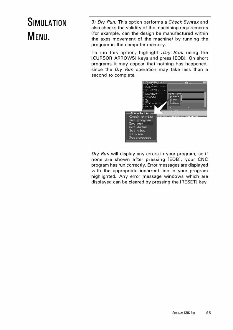
6.5SIMULATE CNC FILE -
3) Dry Run. This option performs a Check Syntax andalso checks the validity of the machining requirements(for example, can the design be manufactured withinthe axes movement of the machine) by running theprogram in the computer memory.
To run this option, highlight 'Dry Run' using the[CURSOR ARROWS] keys and press [EOB]. On shortprograms it may appear that nothing has happened,since the Dry Run operation may take less than asecond to complete.
Dry Run will display any errors in your program, so ifnone are shown after pressing [EOB], your CNCprogram has run correctly. Error messages are displayedwith the appropriate incorrect line in your programhighlighted. Any error message windows which aredisplayed can be cleared by pressing the [RESET] key.
SIMULATION
MENU.

6.6 - SIMULATE CNC FILE
Please note -The co-ordinate values depictedon screenshots are used forillustrative purposes only.
4) Set Datum. This allows the datum point for thegraphical simulation to be set to match theco-ordinates of the 'real' work datum point used onthe billet and CNC File. To run this option, highlight'Set Datum' using the [CURSOR ARROWS] keys andpress [EOB].
Use the following keys to move the position of thedatum point:
[8N UP ARROW] = Purple/blue Crosshair up.[2F DOWN ARROW] = Purple/blue Crosshair down.[6Z RIGHT ARROW] = Purple/blue Crosshair right.[4X LEFT ARROW] = Purple/blue Crosshair left.[9G UPPER RIGHT ARROW] = Yellow tool depth up.[1H LOWER LEFT ARROW] = Yellow tool depth down.
Press the [EOB] to set the graphical datum point, thenthe [RESET] key to clear any unwanted menus fromthe screen.
9G
1H
8N
2F
6Z4X
SIMULATION
MENU.

6.7SIMULATE CNC FILE -
5) Set View. This allows the detail level of the planpictorial view to be selected in the view editor. Toselect this option, highlight 'Set View' using the[CURSOR ARROWS] keys and press [EOB].
If the simulation window is set to display 3d views,the view editor will operate in plan view when the 'SetView' option is selected. The next time the CNC File isrun, the 3d view will be that chosen in the view editor.
Now, when 'Run Program' is selected, the planpictorial view shown will be the one previouslychosen in the 'Set View' option.
[JOG] keytoggles aroundthe different
views.
Press the [JOG] key to cycle through the differentviews. To select the view highlighted press the [EOB]key.
Close-up view ofwork only.
Close-up view ofwork and table.
SIMULATION
MENU.

6.8 - SIMULATE CNC FILE
6) 3d View. This shows the simulation graphic as a 3dimensional view, rather than a plan view. To selectthis option, highlight '3d View' using the [CURSORARROWS] keys and press [EOB].
Please note -The co-ordinate values depictedon screenshots are used forillustrative purposes only.
The [PAGE UP] key can be used to toggle between aback or front 3d view of the design.
SIMULATION
MENU.
continued....

6.9SIMULATE CNC FILE -
SIMULATION
MENU.6) 3d View. continued....
The [8N UP ARROW] key and [2F DOWN ARROW]keys can be used to establish a cross section pointthrough the "Y" plane (indicated by a small light bluetriangle on the righthand side if the 3d billet). Todisplay the cross section at the point selected, pressthe [PAGE DOWN] key.
Use [8N UPARROW] and [2FDOWN ARROW]keys to move bluetriangle marker.
Use [PAGEDOWN] key toswitch to crosssectional 3d view.

6.10 - SIMULATE CNC FILE
7) Post Process. This feature requires the optionalDenford Universal Post Processor software in order tofunction. The Desktop Tutor can be used in conjuctionwith the Denford Universal Post Processor to translatea CNC File into different control languages.
To select this option, highlight 'Post Process' usingthe [CURSOR ARROWS] keys and press [EOB].
When the [EOB] key is pressed, a new file is createdfor the Denford Universal Post Processor software,based upon the original CNC File currently loaded inthe controller. This new file is saved to the currentlyselected drive and directory with the same name asthe CNC File currently loaded in the controller, but adifferent file extension, ".tnc". The original CNC File isunaffected by this operation. Note - no messagewindow will be displayed to indicate that this new".tnc" file has been created.
SIMULATION
MENU.

7.1RUN CNC FILE -
RUN
CNC FILE.
Keys Helpbox.The following keys are used in this section:[AUTO][CYCLE START]
Tutor keypad.
To run a CNC File, the machine needs to be set inAuto Mode. This is selected by pressing the [AUTO]key.
To start the CNC File, press the [CYCLE START] key.
The CNC File will now start to scroll, line by line, in theupper half of the display screen. At the same time, theco-ordinates, feedrate and spindle speed are shown,in the lower half of the display screen. These areupdated, according to the point reached in the CNCFile (the particular CNC File line reached is shown'highlighted').
Please note -The co-ordinate values depictedon screenshots are used forillustrative purposes only.

7.2 - RUN CNC FILE

7.3PAUSING CNC FILE -
PAUSING
CNC FILE.
Keys Helpbox.The following keys are used in this section:[CYCLE STOP], [CYCLE START], [RESET][PAGE UP ARROW], [EDIT], [AUTO]
Tutor keypad.
To pause a CNC File, press the [CYCLE STOP] key.This will set the current feedrate of the tool to 'zero',displaying the message 'Feed HOLD'.
Note, the spindle will still continue to rotate at a setspeed.
To resume the CNC File, press the [CYCLE START]key.
Please note -The co-ordinate values depictedon screenshots are used forillustrative purposes only.
Press the [RESET] key to clear the error message shownabove.
The CNC File will need to be manually reset back to itsoriginal starting point, if required. This can be achievedby two methods:
1) Use the [PAGE UP] arrow key until the originalstarting point of the CNC File is reached.
2) Select Edit Mode by pressing the [EDIT] key, thenpress the [RESET] key. This will reset the CNC File toits start point. Press the [AUTO] key to return themachine back to Auto Mode.
To stop a CNC File, press the [CYCLE STOP] key topause, then press the [RESET] key to abort the run.

7.4 - PAUSING CNC FILE

7.5OVERRIDING SPINDLE SPEED -
The spindle speed of the machine can be manuallyoverridden during a machining operation using thepotentiometer control dial fitted on the lower front panelof the machine (illustrated below).
On machines not fitted with this control dial, the tutorkeypad is used to override the spindle speed (explainedon the next page).
Note, the spindle speed override feature will onlyoperate when speeds are actually being applied to thework (ie, during a machining operation).
On machines fitted with a potentiometer control dial,the spindle speed of the tool is manually adjusted byrotating the dial.
OVERRIDING
SPINDLE SPEED.
OVERRIDING
SPINDLE SPEED
- POTENTIOMETER
CONTROLS.
To increase the spindle speed, rotate the dialclockwise - as the dial is turned the 'faster' spindlespeed will be updated and displayed on the controlscreen.
To decrease the spindle speed, rotate the dialanticlockwise - as the dial is turned the 'slower'spindle speed will be updated and displayed on thecontrol screen.
SpindleOverride- +
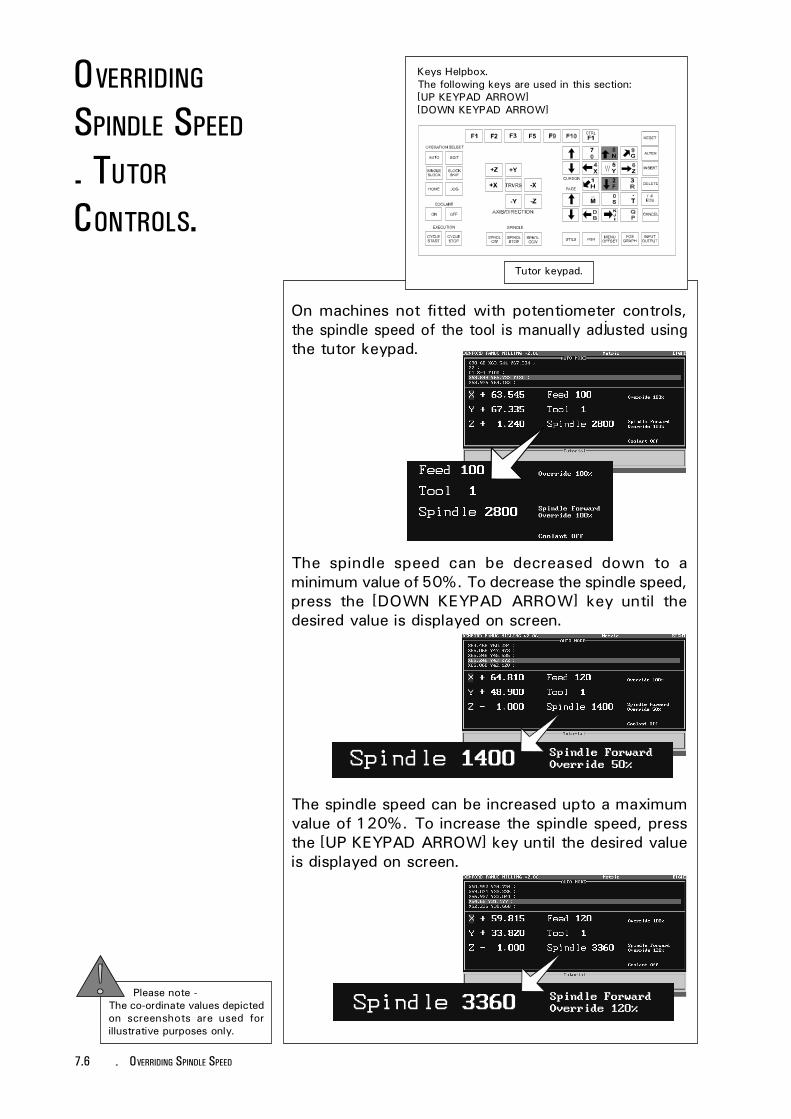
7.6 - OVERRIDING SPINDLE SPEED
Tutor keypad.
Please note -The co-ordinate values depictedon screenshots are used forillustrative purposes only.
OVERRIDING
SPINDLE SPEED
- TUTOR
CONTROLS.
Keys Helpbox.The following keys are used in this section:[UP KEYPAD ARROW][DOWN KEYPAD ARROW]
The spindle speed can be increased upto a maximumvalue of 120%. To increase the spindle speed, pressthe [UP KEYPAD ARROW] key until the desired valueis displayed on screen.
The spindle speed can be decreased down to aminimum value of 50%. To decrease the spindle speed,press the [DOWN KEYPAD ARROW] key until thedesired value is displayed on screen.
On machines not fitted with potentiometer controls,the spindle speed of the tool is manually adjusted usingthe tutor keypad.

7.7OVERRIDING FEEDRATE -
The feedrate of the machine can be manuallyoverridden during a machining operation using thepotentiometer control dial fitted on the lower front panelof the machine (illustrated below).
On machines not fitted with this control dial, the tutorkeypad is used to override the feedrate (explained onthe next page).
Note, the feedrate override feature will only operatewhen feedrates are actually being applied to the work(ie, during a machining operation).
OVERRIDING
FEED RATE.
OVERRIDING
FEED RATE
- POTENTIOMETER
CONTROLS.
On machines fitted with a potentiometer control dial,the feedrate of the tool is manually adjusted byrotating the dial.
To increase the feedrate, rotate the dial clockwise - asthe dial is turned the 'faster' feedrate will be updatedand displayed on the control screen.
To decrease the feedrate, rotate the dial anticlockwise- as the dial is turned the 'slower' feedrate will beupdated and displayed on the control screen.
FeedrateOverride- +
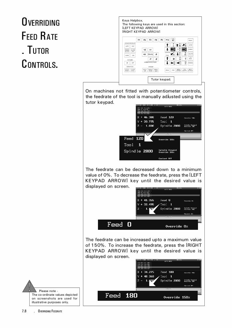
7.8 - OVERRIDING FEEDRATE
Please note -The co-ordinate values depictedon screenshots are used forillustrative purposes only.
Tutor keypad.
Keys Helpbox.The following keys are used in this section:[LEFT KEYPAD ARROW][RIGHT KEYPAD ARROW]
OVERRIDING
FEED RATE
- TUTOR
CONTROLS.
On machines not fitted with potentiometer controls,the feedrate of the tool is manually adjusted using thetutor keypad.
The feedrate can be increased upto a maximum valueof 150%. To increase the feedrate, press the [RIGHTKEYPAD ARROW] key until the desired value isdisplayed on screen.
The feedrate can be decreased down to a minimumvalue of 0%. To decrease the feedrate, press the [LEFTKEYPAD ARROW] key until the desired value isdisplayed on screen.

7.9EMERGENCY STOP -
EMERGENCY
STOP.
Machines with anintegrated controller.
Machines controlledby a PC.
LOCATION OF EMERGENCY
STOP BUTTON.
The red Emergency Stop button is located in twopositions, according to the type of machine being used:
1) Machines controlled by a PC - Located on the frontof the lower machine panel.
2) Machines with an integrated controller - Located onthe controller casing (at the right of the displayscreen).

7.10 - EMERGENCY STOP
EMERGENCY
STOP.
Please note -The co-ordinate values depictedon screenshots are used forillustrative purposes only.
When pressed, the Emergency Stop button willimmediately halt the progress of a program along withany spindle and axis movement.
The Emergency Stop button will lock when fully pressedinto its housing. To reset the Emergency Stop button,turn it clockwise or anticlockwise depending upon thetype of switch fitted to release the lockingmechanism. A key may be required on certain machinesto reset the button and allow access back to themachine.
To clear any messages displayed after pressing theEmergency Stop button, press the [RESET] key.
The program will also need to reset back to its originalstarting position (enter Edit Mode by pressing the [EDIT]key and press the [RESET] key until the first lines ofthe program are visible).
The machine axes will need to be homed - see section2.1 "Automatic Search for the Machine Datum Point".

8.1EDITING A CNC FILE -
EDITING ACNC FILE
- SCREEN VIEW
OPTIONS.
Once a CNC File has been loaded, its content can bealtered using the Editor windows in the machinecontrol software.
CNC Files can be edited in two main screen viewoptions:
Please note -The co-ordinate values depictedon screenshots are used forillustrative purposes only.
Edit and Simulate. The CNC File canbe altered using the Editor side of thescreen and then simulated using thegraphical display(plan or 3d).
Edit only. The CNC File can be alteredusing a full screen Editor window.

8.2 - EDITING A CNC FILE
Please note -The co-ordinate values depictedon screenshots are used forillustrative purposes only.
Tutor keypad.
Keys Helpbox.The following keys are used in this section:[F10], [CURSOR ARROWS][EOB], [EDIT]
Select the Main Menu by pressing the [F10] key.Highlight either the 'Edit and Simulate' or 'Edit only'options, using the [CURSOR] keys and press the [EOB]key to select the highlighted option.
Alternatively, pressing the [EDIT] key will directlyaccess the 'Edit and Simulate' option.
EDITING ACNC FILE
- SCREEN VIEW
OPTIONS.
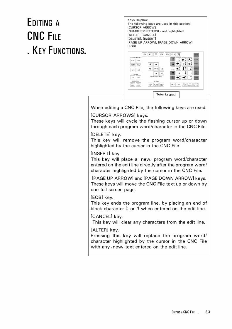
8.3EDITING A CNC FILE -
EDITING ACNC FILE
- KEY FUNCTIONS.
Tutor keypad.
When editing a CNC File, the following keys are used:
[CURSOR ARROWS] keys.These keys will cycle the flashing cursor up or downthrough each program word/character in the CNC File.
[DELETE] key.This key will remove the program word/characterhighlighted by the cursor in the CNC File.
[INSERT] key.This key will place a 'new' program word/characterentered on the edit line directly after the program word/character highlighted by the cursor in the CNC File.
[PAGE UP ARROW] and [PAGE DOWN ARROW] keys.These keys will move the CNC File text up or down byone full screen page.
[EOB] key.This key ends the program line, by placing an end ofblock character (; or /) when entered on the edit line.
[CANCEL] key. This key will clear any characters from the edit line.
[ALTER] key.Pressing this key will replace the program word/character highlighted by the cursor in the CNC Filewith any 'new' text entered on the edit line.
Keys Helpbox.The following keys are used in this section:[CURSOR ARROWS][NUMBERS/LETTERS] - not highlighted[ALTER], [CANCEL][DELETE], [INSERT][PAGE UP ARROW], [PAGE DOWN ARROW][EOB]

8.4 - EDITING A CNC FILE
EDITING ACNC FILE
- EDITOR
WINDOW LAYOUT.
All example screenshots are shown using the 'Edit andSimulate' option.
The CNC File Editor window, in the 'Edit and Simulate'option, is displayed by default on the left side of thescreen. To alter the screen display properties, seesection 10.3 'Change Settings - Editor' and section10.15 'Change Settings - Miscellaneous'.
The general layout of the CNC File Editor window isshown below:
B) Editorcursor.
C) Edit line.
A) Cursor positioninformation bar.
A) The Cursor position informationbar displays the exact location of thecursor by program line and column.
B) The yellow Editor cursor highlightsthe program word or character that canbe edited. In this example it highlightsthe program word 'S2800', referring tothe spindle speed.
C) The Edit line (at the bottom of theEditor window) is the area of thedisplay where 'new' program words/lines can be written, then inserted intothe CNC File. In this example, a 'new'spindle speed of 'S2000' has beenentered on the edit line, using the tutorkeypad.

8.5EDITING A CNC FILE -
Keys Helpbox.The following keys are used in this section:[CURSOR ARROWS][NUMBERS/LETTERS] - not highlighted[ALTER], [CANCEL][DELETE], [INSERT][PAGE UP ARROW], [PAGE DOWN ARROW][EOB]
Tutor keypad.
EDITING ACNC FILE.
Using the 'Edit and Simulate' screen shown on theprevious page as an example, the CNC File could beedited in a variety of different ways.
SELECTING PROGRAM TEXT.
The 'new' program word 'S2000' is entered on theedit line using the tutor keypad.
Any 'new' program word, or set of words, is alwaysentered from the edit line.
The [CANCEL] key is used to clear unwanted text fromthe edit line.
The [EOB] key will enter any text entered on the editline as a 'new' program line in the CNC File.
The required section of the program, the program word'S2800' is highlighted using the [CURSOR ARROWS]keys. To move through a large CNC File quickly usethe [PAGE UP ARROW] and [PAGE DOWN ARROW] keys.

8.6 - EDITING A CNC FILE
EDITING ACNC FILE.
INSERTING AND DELETING PROGRAM TEXT.
If the [INSERT] key is pressed, any 'new' text enteredon the edit line is placed directly after the last programword/character highlighted by the cursor. The 'new'program line reads 'M3 S2800 S2000 ;' as shownabove.
To remove the highlighted program word 'S2000', the[DELETE] key would be pressed.
Edit line text.
ALTERING A PROGRAM LINE.
If the [ALTER] key is pressed when 'S2000' is enteredon the edit line and 'S2800' is highlighted by thecursor, 'S2800' is replaced by 'S2000'.
Edit line text.

9.1MAIN MENU - PRINT, LINKS AND UTILITIES -
MAIN MENU
- LINK TO
CONTROLLER.
Keys Helpbox.The following keys are used in this section:[F10], [CURSOR ARROWS][EOB], [RESET]
Tutor keypad.
The Link to Controller option allows a CNC File to besent or received from an external FANUC controller.This option is useful for CNC Files that are designedand generated in 'clean' working areas before beingsent down to the machining area, or CNC Files thatare larger than the capacity of one floppy disk.
Select the Main Menu by pressing the [F10] key.Highlight 'Link to Controller' using the [CURSORARROWS] keys and press the [EOB] key.
Press the [RESET] key to remove any unwanted menusfrom the screen.
The Link to Controller Sub-menu contains two options :
1) Load from Controller. This option will load the CNCFile from the external FANUC controller.
2) Downfeed to Controller. This option will send theCNC File to the external FANUC controller.
Select the required option using the [CURSORARROWS] keys, then press the [EOB] key.

9.2 - MAIN MENU - PRINT, LINKS AND UTILITIES
MAIN MENU
- PRINT.
Keys Helpbox.The following keys are used in this section:[F10], [CURSOR ARROWS][EOB], [RESET]
Tutor keypad.
The Print option allows you to generate a paper copyof the currently loaded CNC File from a connectedprinter.
Select the Main Menu by pressing the [F10] key.Highlight 'Print' using the [CURSOR ARROWS] keysand press the [EOB] key.
The Printing Sub-menu contains two options :
1) Line format with errors. This option will print theCNC File as displayed in the Editor window withany errors highlighted.
2) Line format with no errors. This option will print theCNC File as displayed in the Editor window withouthighlighting any errors.
continued....

9.3MAIN MENU - PRINT, LINKS AND UTILITIES -
MAIN MENU
- PRINT.continued....
Select the required option using the [CURSORARROWS] keys, then press the [EOB] key.
Press the [RESET] key to remove any unwanted menusfrom the screen.
PRINTING ERRORS.
If the printer does not respond, check the following :
1) Is the cabling between the computer/control boxand printer secure?
2) Is the printer set for Parallel or Serialcommunications?
3) Have the correct parameters been set in the'Settings Menu - Print Device' (see section 10.11) ?
4) Is the printer switched 'on' and is there enoughpaper available for the printout?
PAGE LAYOUT ERRORS.
If the layout on the printout is incorrect, the page widthsand linefeeds can be changed in the 'Settings Menu -Print Page Layout' (see section 10.12).

9.4 - MAIN MENU - PRINT, LINKS AND UTILITIES
MAIN MENU
- REMOTE LINK.
Keys Helpbox.The following keys are used in this section:[F10], [CURSOR ARROWS][EOB], [RESET], [Y], [N]
Tutor keypad.
The Remote Device option allows a CNC File to besent or received from a remote device, such asanother computer, paper tape punch reader, datacarrier etc....
Select the Main Menu by pressing the [F10] key.Highlight 'Remote Link' using the [CURSOR ARROWS]keys and press the [EOB] key.
The Remote Link Sub-menu contains two options :
1) Load from device. This option will load the CNC Filefrom the remote device.
2) Send to device. This option will send the CNC Fileto the remote device.
Select the required option using the [CURSORARROWS] keys, then press the [EOB] key.
9.5MAIN MENU - PRINT, LINKS AND UTILITIES -
MAIN MENU
- REMOTE LINK.LOAD FROM DEVICE.If there is a CNC File currently loaded in the controlsoftware, you will be asked whether to merge the CNCFile when loading from the remote device.
Press the [Y] to merge both CNC Files into one and the[N] key to clear the current CNC File from the controlsoftware.
SEND TO DEVICE.You will be prompted with a 'Ready to send?'message. Press the [Y] key to send the CNC File andthe [N] key to abort the operation.
During CNC File transfer, a 'Transmitting to device'message window will be displayed, showing thenumber of bytes and lines sent. A 'Transmissioncompleted' message will be displayed to confirm thatthe whole CNC File has been sent to the remotedevice.
Press the [RESET] key to remove any unwantedmessages and menus from the screen.
COMMUNICATION ERRORS.
If an error is encountered, check the following :
1) Is the cabling between the computer/control boxand remote device secure?
2) Is the cable connected to the correct ports with thecorrect pin connections?
3) Have the correct parameters been set in the'Settings Menu - Remote Link' (see section 10.14)?
4) Is the remote device switched 'on' and ready tosend or receive data?

9.6 - MAIN MENU - PRINT, LINKS AND UTILITIES
MAIN MENU
- UTILITIES.
Keys Helpbox.The following keys are used in this section:[F10], [CURSOR ARROWS][EOB], [RESET]
Tutor keypad.
Select the Main Menu by pressing the [F10] key.Highlight 'Utilities' using the [CURSOR ARROWS] keysand press the [EOB] key.
Press the [EOB] key when 'Dos Access' is highlightedto temporarily exit the control software.
Please note -The DOS Access feature is onlyavailable on machines controlledby an external PC. If an errormessage is displayed whentrying to access DOS, press the[RESET] key.
Other external DOS programs can be run when thecomputer is set in DOS mode. To return to the controlsoftware, type 'EXIT' at the DOS prompt, then pressthe [EOB] key, when prompted.
Press the [RESET] key to remove any unwanted menusfrom the screen.

10.1CHANGE SETTINGS -
Tutor keypad.
Keys Helpbox.The following keys are used in this section:[F10][CURSOR ARROWS][EOB]
The Change Settings Menu is used to switch on andoff the various options available within the machinecontrol software.
Select the Main Menu by pressing the [F10] key.Highlight 'Settings' using the [CURSOR ARROWS] keyand press the [EOB] key to confirm this choice.
At the Change Settings Menu,select the required option andpress the [EOB] key.
CHANGE
SETTINGS.The Change Settings Menu allows the software to becustomised to suit the requirements of the end user.
When all the options have been fully configured, thesettings should be saved to disk. Each time themachine is started it will load these customised settings.
CHANGE
SETTINGS
- MENU.

10.2 - CHANGE SETTINGS
CHANGE
SETTINGS
- MENU.
The Change Settings Menu contains nine options:
1) Editor. This option allows the CNC File Editorwindow to be customised.
2) Simulation. This option allows the graphics andviews in the Simulation window to be customised.
3) Print Device. This option allows any printersattached to the machine controller to beconfigured.
4) Print Page Layout. This option allows the layout ofany printouts to be customised.
5) Controller Link. This option allows thecommunication protocols between the machine andthe controller to be configured.
6) Remote Link. This option allows thecommunication protocols between the machinecontroller and an external device to be configured.
7) Miscellaneous. This option allows the units ofmeasurement, user's name and screen text size tobe customised.
8) Load Settings. This option allows a collection ofsettings to be loaded.
9) Save Settings. This option allows the currentcollection of settings to be saved.

10.3CHANGE SETTINGS -
CHANGE
SETTINGS
- EDITOR.
Tutor keypad.
Keys Helpbox.The following keys are used in this section:[CURSOR ARROWS][EOB][RESET]
The Change Settings (Editor) Menu contains thefollowing options:
1) Auto-error Check. This option, when set to 'Yes',will check the validity of CNC program lines as theyare manually entered. When the [EOB] key is pressed(to signify the end of a program line) an errordescription box will be displayed if an error isencountered. Press the [RESET] key to clear the errordescription box. The cursor will highlight where on theprogram line the error occured.
To select this option, highlight 'Auto-error Check' usingthe [CURSOR ARROWS] keys and press the [EOB] key.
The screen will indicate the current setting of theoption. Continual pressing of the [EOB] key will togglethe option between 'Yes' and 'No'.
When the setting is correct, press the [RESET] keyuntil all the menus have been removed from the screen.

10.4 - CHANGE SETTINGS
2) Marking Mode. This option, will select between the'Drag' or 'Anchor' methods of cut and pasting partCNC Files. This feature is ONLY available on qwerty(offline) versions of the control software.
The Marking Mode option has no effect on themachine controlling software.
3) Edit Only Mode. This option toggles the preferenceof the Edit Only display between 'Text' or 'Graphics'.In Graphics Mode preference is given to theappearance of the alphabet characters used by thecontrol software (ie, the software drivers). In Text Modepreference is given to the computer video card, givinga slight speed increase when scrolling the text anddirect access to specific character maps controlled bythe video card (ie, the computer drivers).
To select this option, highlight 'Edit Only Mode' usingthe [CURSOR ARROWS] keys and press the [EOB] key.
The screen will indicate the current setting of theoption. Continual pressing of the [EOB] key will togglethe option between 'Text' and 'Graphics'.
When the setting is correct, press the [RESET] keyuntil all the menus have been removed from the screen.
CHANGE
SETTINGS
- EDITOR.

10.5CHANGE SETTINGS -
4) Editor On Left. This option, when set to 'Yes', willdisplay the CNC editor window on the left side of thescreen (when the control is set in 'Edit and Simulate'Mode). Selecting 'No' will display the CNC editorwindow on the right side of the screen (when thecontrol is set in 'Edit and Simulate' Mode).
To select this option, highlight 'Editor On Left' usingthe [CURSOR ARROWS] keys and press the [EOB] key.
The screen will indicate the current setting of theoption. Continual pressing of the [EOB] key will togglethe option between 'Yes' and 'No'.
When the setting is correct, press the [RESET] keyuntil all the menus have been removed from the screen.
'Editor On Left' set to 'Yes'.
'Editor On Left' set to 'No'.
CHANGE
SETTINGS
- EDITOR.

10.6 - CHANGE SETTINGS
CHANGE
SETTINGS
- SIMULATION.
Tutor keypad.
Keys Helpbox.The following keys are used in this section:[CURSOR ARROWS][EOB][RESET]
The Change Settings (Simulation) Menu contains thefollowing options:
1) Simulation Window. This option will switch the sizeof the graphical simulation window between wide andnormal.
Normal splits the display screen to 50% editorwindow and 50% graphical simulation window. Wideincreases the graphical simulation window, at theexpense of the editor window size.
To select this option, highlight 'Simulation Window'using the [CURSOR ARROWS] keys and press the[EOB] key.
The screen will indicate the current setting of theoption. Continual pressing of the [EOB] key will togglethe option between 'normal' and 'wide'.
When the setting is correct, press the [RESET] keyuntil all the menus have been removed from the screen.
continued....
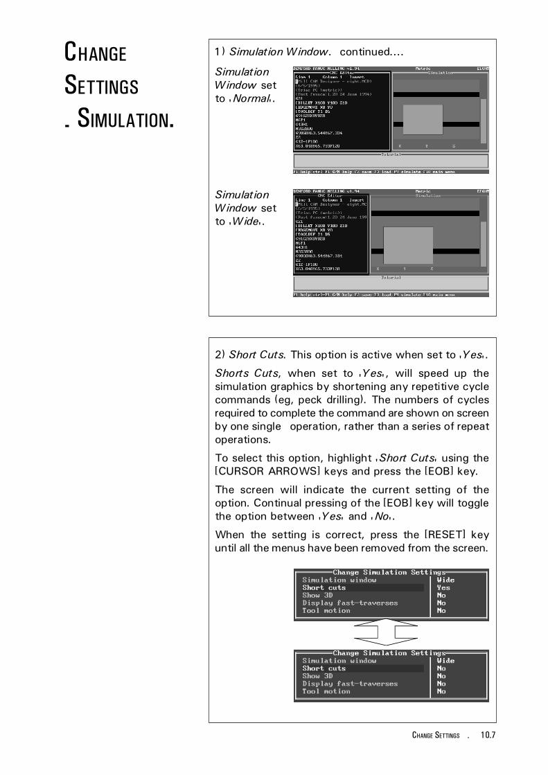
10.7CHANGE SETTINGS -
1) Simulation Window. continued....
2) Short Cuts. This option is active when set to 'Yes'.
Shorts Cuts, when set to 'Yes', will speed up thesimulation graphics by shortening any repetitive cyclecommands (eg, peck drilling). The numbers of cyclesrequired to complete the command are shown on screenby one single operation, rather than a series of repeatoperations.
To select this option, highlight 'Short Cuts' using the[CURSOR ARROWS] keys and press the [EOB] key.
The screen will indicate the current setting of theoption. Continual pressing of the [EOB] key will togglethe option between 'Yes' and 'No'.
When the setting is correct, press the [RESET] keyuntil all the menus have been removed from the screen.
SimulationWindow setto 'Normal'.
SimulationWindow setto 'Wide'.
CHANGE
SETTINGS
- SIMULATION.

10.8 - CHANGE SETTINGS
3) Show 3d. This option, when set to 'Yes', willdisplay the work as a three dimensional object.
To select this option, highlight 'Show 3d' using the[CURSOR ARROWS] keys and press the [EOB] key.
The screen will indicate the current setting of theoption. Continual pressing of the [EOB] key will togglethe option between 'Yes' and 'No'.
When the setting is correct, press the [RESET] keyuntil all the menus have been removed from the screen.
Now, when 'Run Program' is selected, the work willbe displayed in 3d, throughout the running of theprogram cycle.
CHANGE
SETTINGS
- SIMULATION.

10.9CHANGE SETTINGS -
4) Display Fast Traverses. This option is active whenset to 'Yes' (not available for 3d views).
Display Fast Traverses, when set to 'Yes', will showall fast traverse movements as yellow lines. Lines cutinto the billet are shown in white.
To select this option, highlight 'Display Fast Traverses' usingthe [CURSOR ARROWS] keys and press the [EOB] key.
The screen will indicate the current setting of theoption. Continual pressing of the [EOB] key will togglethe option between 'Yes' and 'No'.
When the setting is correct, press the [RESET] keyuntil all the menus have been removed from the screen.
Run CNC File with....
Display FastTraverses set to'No'.
Display FastTraverses set to'Yes'.
CHANGE
SETTINGS
- SIMULATION.

10.10 - CHANGE SETTINGS
5) Tool Motion. This option, when set to 'Yes' willdisplay the movement and path of the tool as it cutsthe material.
To select this option, highlight 'Tool Motion' using the[CURSOR ARROWS] keys and press the [EOB] key.
The screen will indicate the current setting of theoption. Continual pressing of the [EOB] key will togglethe option between 'Yes' and 'No'.
When the setting is correct, press the [RESET] keyuntil all the menus have been removed from the screen.
Now, when 'Run Program' is selected, the tool motionwill be shown , throughout the running of the programcycle. The program cycle will run considerably slowerwith this option switched 'on'.
Tool path - traverse
Tool path - cutting.
Cutting Tool tip.
CHANGE
SETTINGS
- SIMULATION.
Please note -The Tool Motion feature is notavailable when CNC Files usecutter diameters of less than3mm.

10.11CHANGE SETTINGS -
CHANGE
SETTINGS
- PRINT DEVICE.
Tutor keypad.
Keys Helpbox.The following keys are used in this section:[CURSOR ARROWS][EOB][RESET]
Please note -Any changes made to thesesettings should be carried out byeither your IT Manager orcomputer technician.
When the setting is correct, press the [RESET] keyuntil all the menus have been removed from the screen.
The Print Device option is used to configure thesettings for any printers attached to the machinecontroller.
There are three different printer options, selected bypressing the [EOB] key when the cursor is highlightingthe 'Device : Type' :
1) DOS Device - A DOS Device is normally the parallelport which can be set to LPT1. LPT2 or PRN.Select this option if your printer has a parallel port.
2) Serial Device - Select the individual settings usingthe [CURSOR ARROWS] keys and press the [EOB]key to toggle between the different values.
3) File - This option is used to save the CNC File ondisk, for printing off at a later date. The currentfilename will be saved with an extension ".LST".

10.12 - CHANGE SETTINGS
CHANGE
SETTINGS
- PRINT PAGE
LAYOUT.Tutor keypad.
Keys Helpbox.The following keys are used in this section:[CURSOR ARROWS][EOB][RESET]
Please note -Any changes made to thesesettings should be carried out byeither your IT Manager orcomputer technician.
The Print Page Layout option is used to customise anyprintouts taken from the control software.
If several printers are available, save each individualsetting with a different filename (see page 10.18).
Select the individual settings on the Change Print PageLayout Menu using the [CURSOR ARROWS]. Pressthe [EOB] key to move the cursor across, type in therequired values, then press the [EOB] key to confirmthe new value.
When the setting is correct, press the [RESET] keyuntil all the menus have been removed from the screen.

10.13CHANGE SETTINGS -
CHANGE
SETTINGS
- CONTROLLER
LINK.Tutor keypad.
Keys Helpbox.The following keys are used in this section:[CURSOR ARROWS][EOB][RESET]
Please note -Any changes made to thesesettings should be carried out byeither your IT Manager orcomputer technician.
The Controller Link option is used to configure thecommunication protocols between the machine andthe controller.
On PC controlled machines, The PC serial (COM) portsare used for communicating. Usually, COM 1 is usedto connect the PC to the desktop tutor keypad andCOM 2 is used to connect the PC to the port labelled"RS232" on the machine electrical control box. In thiscase, COM 2 is the controller link.
On machines with an integrated controller, thecontroller link is "hidden" inside the electrical controlbox. In this case, the option is ineffective and shouldNOT be altered.
To select the individual settings use the [CURSORARROWS] keys and press the [EOB] key to togglebetween the different values.
When the settings are correct, press the [RESET] keyuntil all the menus have been removed from the screen.
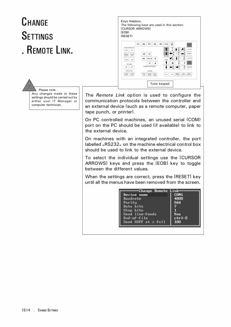
10.14 - CHANGE SETTINGS
CHANGE
SETTINGS
- REMOTE LINK.
Tutor keypad.
Keys Helpbox.The following keys are used in this section:[CURSOR ARROWS][EOB][RESET]
Please note -Any changes made to thesesettings should be carried out byeither your IT Manager orcomputer technician.
The Remote Link option is used to configure thecommunication protocols between the controller andan external device (such as a remote computer, papertape punch, or printer).
On PC controlled machines, an unused serial (COM)port on the PC should be used (if available) to link tothe external device.
On machines with an integrated controller, the portlabelled "RS232" on the machine electrical control boxshould be used to link to the external device.
To select the individual settings use the [CURSORARROWS] keys and press the [EOB] key to togglebetween the different values.
When the settings are correct, press the [RESET] keyuntil all the menus have been removed from the screen.

10.15CHANGE SETTINGS -
The Change Settings (Miscellaneous) Menu containsthe following options:
1) Global Units. This option will display the axesco-ordinates and feedrate in either Metric units(millimetres) or Imperial units (inches).
To select this option, highlight 'Global Units' using the[CURSOR ARROWS] keys and press the EOB] key.Continual pressing of the [EOB] key will toggle theoption between the two settings.
When the setting is correct, press the [RESET] keyuntil all the menus have been removed from the screen.
CHANGE
SETTINGS
- MISCELLANEOUS.
Tutor keypad.
Keys Helpbox.The following keys are used in this section:[CURSOR ARROWS][EOB], [RESET][NUMBERS] - not highlighted

10.16 - CHANGE SETTINGS
CHANGE
SETTINGS
- MISCELLANEOUS.
2) User's Name. This option allows the user's name tobe printed out on any subsequent CNC File printouts.
To select this option, highlight 'User's Name' using the[CURSOR ARROWS] keys and press the [EOB] key tomove the cursor across to the text 'A N Other'. Enter thenew text using the [NUMBERS] keys and press the [EOB]key to confirm. Note that alphabet characters can onlybe entered when using a qwerty keyboard.
When the setting is correct, press the [RESET] keyuntil all the menus have been removed from the screen.
3) Screen Text Size. This option, when set to 'Large',will set the text size to 25 lines on screen :
Please note -The screen text size option willoperate when the main screendisplay is set to "EGA" mode butwill NOT operate when set to"VGA" mode. The screen modecan be altered by opening a DOSwindow and editing the"fanuc.go" file, found in the rootof the machine directory.
When set to 'Small', the text size is set to 43 lines onscreen :
To select this option, highlight 'Screen Text Size'using the [CURSOR ARROWS] keys and press the EOB]key. Continual pressing of the [EOB] key will togglethe option between the two settings.
When the setting is correct, press the [RESET] keyuntil all the menus have been removed from the screen.

10.17CHANGE SETTINGS -
CHANGE
SETTINGS
- LOAD SETTINGS.
Tutor keypad.
Keys Helpbox.The following keys are used in this section:[CURSOR ARROWS][EOB][RESET]
The Load Settings option is used to load any previouslysaved software settings onto the controller.
When the Load Settings option is selected,the defaultsettings filename will appear in the edit window. Thedefault filename is 'FANUCM' :
To list all of the available Settings Files, clear the editwindow by pressing the [ALTER] key and press [EOB].Select the required settings file from the list and pressthe [EOB] key to load the highlighted file :
When the Setting File has been loaded, press the[RESET] key until all the menus have been removedfrom the screen.
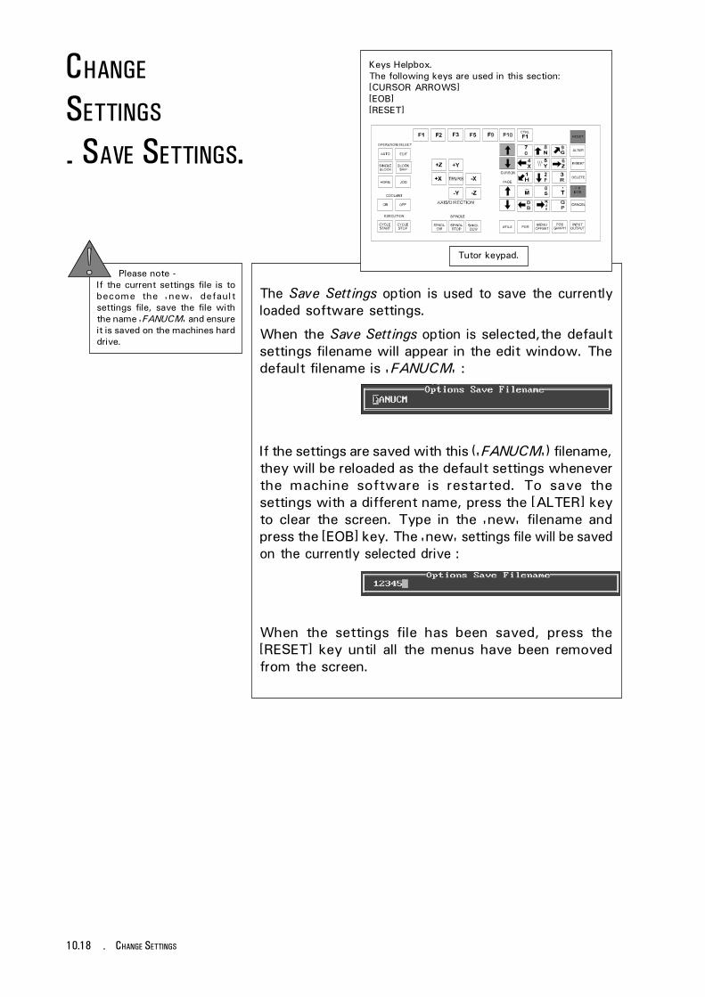
10.18 - CHANGE SETTINGS
CHANGE
SETTINGS
- SAVE SETTINGS.
Tutor keypad.
Keys Helpbox.The following keys are used in this section:[CURSOR ARROWS][EOB][RESET]
The Save Settings option is used to save the currentlyloaded software settings.
When the Save Settings option is selected,the defaultsettings filename will appear in the edit window. Thedefault filename is 'FANUCM' :
When the settings file has been saved, press the[RESET] key until all the menus have been removedfrom the screen.
Please note -If the current settings file is tobecome the 'new' defaultsettings file, save the file withthe name 'FANUCM' and ensureit is saved on the machines harddrive.
If the settings are saved with this ('FANUCM') filename,they will be reloaded as the default settings wheneverthe machine software is restarted. To save thesettings with a different name, press the [ALTER] keyto clear the screen. Type in the 'new' filename andpress the [EOB] key. The 'new' settings file will be savedon the currently selected drive :

11.1PROGRAM STRUCTURE, LISTINGS AND DIRECTIVES -
PROGRAMMING
TERMS AND
CONVENTIONS.
This section describes the composition of a basic CNCpart program, listing the following terms used:
1) Program Address characters.
2) G Codes used on Denford CNC Milling Machines.
3) M Codes used on Denford CNC Milling Machines.
4) Denford Directives (program codes specific toDenford CNC Machines).
A Part Program is a list of coded instructions whichdescribes how the designed component, or part, willbe manufactured. This part program is also called theCNC File.
These coded instructions are called data - a series ofletters and numbers. The part program includes all thegeometrical and technological data to perform therequired machine functions and movements tomanufacture the part.
The part program can be further broken down intoseparate lines of data, each line describing a particularset of machining operations. These lines, which run insequence, are called blocks.
A block of data contains words, sometimes calledcodes. Each word refers to a specific cutting/movement command or machine function. Theprogramming language recognised by the CNC, themachine controller, is an I.S.O. code, which includesthe G and M code groups.
Each program word is composed from a letter, calledthe address, along with a number.
These terms are illustrated on the next page....
WHAT IS APART
PROGRAM ?

11.2 - PROGRAM STRUCTURE, LISTINGS AND DIRECTIVES
COMPOSITION
OF A PART
PROGRAM.
The component is designed "on-screen" using Mill CAMDesigner.
This CAD/CAM software package automaticallygenerates a G code part program suitable for DenfordCNC machines, listed on the bottom left of this page....
PART PROGRAM EXAMPLE -(MILL CAM DESIGNER - TRIANG.MCD)(3/3/1997)(NOVAMILL (METRIC))(POST FANUCM:1.2Ø 24 JUNE 1994)G21[BILLET X8Ø Y55 Z1Ø[EDGEMOVE XØ YØ[TOOLDEF T1 D2NØØ1Ø G91G28XØYØZØ;NØØ2Ø M6T1;NØØ3Ø G43H1;NØØ4Ø M3S15ØØ;NØØ5Ø G9ØGØX4ØY48;NØØ6Ø Z2;NØØ7Ø G1Z-Ø.5F1ØØ;NØØ8Ø X72Y16F15Ø;NØØ9Ø X8;NØ1ØØ X4ØY48;NØ11Ø GØZ2;NØ12Ø X24Y32;NØ13Ø G1Z-1F1ØØ;NØ14Ø X56F15Ø;NØ15Ø X4ØY16;NØ16Ø X24Y32;NØ17Ø GØZ2;NØ18Ø M5;NØ19Ø G91G28XØYØZØ;NØ2ØØ M3Ø;
ADDRESS EXAMPLE - G
WORD EXAMPLE - GØ1
BLOCK EXAMPLE - NØ13Ø G1Z-1F1ØØ;
DENFORD DIRECTIVE EXAMPLE - [BILLET

11.3PROGRAM STRUCTURE, LISTINGS AND DIRECTIVES -
LISTING OF
ADDRESS
CHARACTERS.
N - Program Sequence (line) number.
X - Primary motion in X axis.
Y - Primary motion in Y axis.
Z - Primary motion in Z axis.
G - Preparatory functions.
I - Incremental distance parallel to X axis.
J - Incemental distance parallel to Y axis.
K - Incremental distance parallel to Z axis.
R - Radius.
M - Miscellaneous functions.
T - Tool numbers.
S - Spindle speeds.
F - Feed rates.

11.4 - PROGRAM STRUCTURE, LISTINGS AND DIRECTIVES
G CODES
LISTING FOR
DENFORD
CNC MILLING
MACHINES.
NOTES.G codes from group Ø are non-modal (they must beprogrammed into every program block when required).
All other G codes are modal (they remain active throughsubsequent program blocks, until replaced or cancelledby a G code from their particular group).
The G codes indicated by an asterisk (*) arereactivated as defaults when the machine started.
Note - Not all G codes apply to each machine.
G Code. Group. Function.
GØØ 1 Positioning (Rapid Traverse)GØ1 1 Linear Interpolation (Cutting Feed)GØ2 1 Circular Interpolation CWGØ3 1 Circular Interpolation CCWGØ4 Ø Dwell, Exact StopG2Ø 6 Imperial Data Input (Inches)G21 6 Metric Data Input (Millimetres)G28 Ø Reference Point ReturnG4Ø 7 Cutter Compensation CancelG41 7 Cutter Compensation LeftG42 7 Cutter Compensation RightG73 9 Peck Drilling CycleG74 9 Counter TappingG76 9 Fine BoringG8Ø* 9 Canned Cycle CancelG81 9 Drilling Cycle, Spot BoringG82 9 Drilling Cycle, Counter BoringG83 9 Peck Drilling CycleG84 9 TappingG85 9 Boring CycleG86 9 Boring CycleG87 9 Back Boring CycleG89 9 Boring CycleG9Ø* 3 Absolute ZeroG91 3 Incremental CommandG94* 5 Feed per MinuteG95 5 Feed per RevolutionG98* 1Ø Return to Initial Point in Canned CycleG99 1Ø Return to R in Canned CycleG17Ø Ø Circular PocketG171 Ø Circular PocketG172 Ø Rectangular PocketG173 Ø Rectangular Pocket
Code listing full and correct at the time of printing.

11.5PROGRAM STRUCTURE, LISTINGS AND DIRECTIVES -
M CODES
LISTING FOR
DENFORD
CNC MILLING
MACHINES.
Note - Not all M codes apply to each machine.
M code. Function.
MØØ* Program Stop
MØ1* Optional Stop
MØ2* Program Reset
MØ3 Spindle Forward (clockwise)
MØ4 Spindle Reverse (counter clockwise)
MØ5* Spindle Stop
MØ6 Automatic Tool Change
MØ8 Coolant On
MØ9* Coolant Off
M1Ø Vice/Work Clamp Open
M11 Vice/Work Clamp Close
M13 Spindle Forward and Coolant On
M14 Spindle Reverse and Coolant On
M19 Spindle Orientation
M2Ø ATC Arm In
M21 ATC Arm Out
M22 ATC Arm Down
M23 ATC Arm Up
M24 ATC Drawbar Unclamp
M25 ATC Drawbar Clamp
M27 Reset Carousel to Pocket One
M3Ø Program Reset and Rewind
M32 Carousel CW
M33 Carousel CCW
M38 Door Open
M39 Door Close
M62 Auxiliary Output 1 On
M63 Auxiliary Output 2 On
continued....

11.6 - PROGRAM STRUCTURE, LISTINGS AND DIRECTIVES
M CODES
LISTING FOR
DENFORD
CNC MILLING
MACHINES.
continued....
M code. Function.
M64 Auxiliary Output 1 Off
M65 Auxiliary Output 2 Off
M66* Wait for Auxiliary Output 1 On
M67* Wait for Auxiliary Output 2 On
M7Ø Mirror in X On
M71 Mirror in Y On
M76 Wait for Auxiliary Output 1 Off
M77 Wait for Auxiliary Output 2 Off
M8Ø Mirror in X Off
M81 Mirror in Y Off
M98 Sub Program Call
M99 Sub Program End and Return
Code listing full and correct at the time of printing.
NOTES.Not all M codes listed are available, all M codes markedwith an asterisk (*) will be performed at the end of aprogram block (ie, after any axis movement).

11.7PROGRAM STRUCTURE, LISTINGS AND DIRECTIVES -
DENFORD
DIRECTIVES.Directives are program terms defined by DenfordLimited.
They are used to help generate the 'Simulation Mode'graphics used by the machine controlling software.
[BILLETThis directive allows a billet that appears in asimulation window to be given a size. The billetdefinition should be placed at the start of a program,after the units of measurement have been set.
Example:
G21
[BILLET X1ØØ.Ø Y9Ø.Ø Z2Ø.Ø
This sets the measure to metric (Note - if set toImperial the units would be inches) and defines thebillet as1ØØmm long by 9Ømm wide, with a depth of2Ømm.
[SUBPROGRAMThis directive allows a program with a non-numericname to be called as a subprogram.
Example:
[SUBPROGRAM Ø2ØØ FRED
M98 PØ2ØØ
This example assigns a subprogram number of Ø2ØØto the program named FRED, then calls the subprogramØ2ØØ.
[TOOLDEFThis directive sets the length and diameter of acutting tool. The length of a tool is the distance fromthe spindle nose to the bottom of the cutter.
Example:
G21
[TOOLDEF T1 D8 Z65
This example defines tool number 1 as being 8mm indiameter, and 65mm long.
11.8 - PROGRAM STRUCTURE, LISTINGS AND DIRECTIVES
DENFORD
DIRECTIVES.[STEPThis directive runs an on-screen program in single steps.This means the program will run one program line, thenwait for the operator to prompt it to move to the nextline; this continues until the program is instructed tostop this function.
The directive applies to both simulation and actualmachining with a program.
[NO STEPThis directive runs an on-screen program withoutsingle steps. This means the program will run asoriginally intended with no pausing, unless a pause isrequested from within the program itself.
The directive applies to both simulation and actualmachining with a program.
[SHOWThis directive allows the machining operations to begraphically simulated on-screen.
[NOSHOWThis directive stops the machining operations frombeing graphically simulated on-screen.
[EDGEMOVEThis directive will move the edges of the billet relativeto the workpiece datum point. For the purposes ofgraphical simulation, the workpiece datum point isusually set as the lower front corner of the billet.
[EDGEMOVE is useful when a workpiece datum pointwritten into a G-code program does not match thisdefault (lower lefthand front corner) position on thebillet.
It moves the graphic display of the billet so theworkpiece datum point in the graphical simulation alignswith the workpiece datum point in the program.
Example:
G21
[EDGEMOVE XØ Y-2Ø
This example moves the billet Ømm on X and -2Ømmon Y from the workpiece datum point.

11.9PROGRAM STRUCTURE, LISTINGS AND DIRECTIVES -
DENFORD
DIRECTIVES.!An exclamation mark is used to display a message inthe tutorial messages window (shown in the lower partof the screen). The message will be shown until it iseither cleared or replaced by another message.
Tutorial messages are shown coloured green, withinthe program, on-screen. Messages must be enteredoff-line since text cannot be entered with the tutorkeyboard.
Example:
! NOW CUTTING 1Ømm BORDER
This example would print the line "NOW CUTTING1Ømm BORDER" in the tutorial messages window inthe lower part of the screen.
?A question mark is used to display a message in thetutorial messages window (shown in the lower part ofthe screen). When the message is displayed theprogram will stop. A keypress is required to set theprogram running again. Any messages will be shownuntil they are either cleared or replaced by anothermessage.
Tutorial messages are shown coloured green withinthe program, on-screen. Messages must be enteredoff-line since text cannot be entered with the tutorkeyboard.
Example:
? CHECK THAT A 6mm SLOT DRILL IS PRESENT
This example would print the line "CHECK THAT A6mm SLOT DRILL IS PRESENT" in the tutorialmessages window and stop the program. A key wouldneed to be pressed to allow the program to continue.
[CLEARThis clears any messages currently displayed in thetutorial messages window.

11.10 - PROGRAM STRUCTURE, LISTINGS AND DIRECTIVES

12.1GLOSSARY -
GLOSSARY.ALLEN HEAD A hexagon shaped hole on the head (top)of a set screw.
These are tightened/loosened using 'allen keys'.
AXIS (AXES) The planes of movement for the cutting tool, usuallyreferred to as X (horizontal left and right, parallel to thefront edge of the table), Y (horizontal forward andbackwards, parallel to the side edge of the table) and Z(directly vertical). Combinations of all 3 allow preciseco-ordinates to be described.
CNC Computer Numerical Control.
CO-ORDINATES Positions or relationships of points or planes.Co-ordinates are usually described using three numbersreferring to the (X,Y,Z) axes, e.g. the co-ordinate(23,35,45) means X axis = +23 units, Y axis = +35units and Z axis = +45 units.
CUTTER SPEED The velocity of the cutting edge of the tool relative tothe workpiece. With circular tools, the cutting speed isrelated to the tool when new (maximum cuttingdiameter). Usually the effect of feedrate is ignored.
CYCLE A sequence of events or commands.
DATUM The point (co-ordinate) from which a series ofmeasurements are taken.
DATUM PLATE The L-shaped bracket used to help locate pieces of workin position on the machine table.
DESKTOP TUTOR The input control keypad for the machine. Keypadoverlays are interchangeable according to the type ofcontroller required.
DIRECTORY An area of a disk containing the names and locations ofthe files it currently holds.

12.2 - GLOSSARY
DISK A computer information storage device, examples, C:(drive) is usually the computers hard (internal) disk andA: (drive) is usually the floppy (portable 3.5" diskette)disk.
DRIVE The controller unit for a disk system.
END OF BLOCK SIGNAL A symbol or indicator that defines the end of a block ofdata. The 'pc' equivalent of the 'return' key.
ERROR The deviation of an attained value from a desired value.
FEEDRATE The rate, in mm/min or in/min at which the cutting toolis advanced into the workpiece. For milling anddrilling, the feedrate applies to the reference point onthe end of the axis of the tool.
FILE An arrangement of instructions or information, usuallyreferring to work or control settings.
HARDWARE Equipment such as the machine tool, the controller, orthe computer.
INCH (OR JOG) CONTROL A manual control button, used when setting-up amachine, which permits the position of machine to bealtered, either by very small pre-defined movements(called Jog steps) or larger continued movements (calledcontinuous).
MACHINE CODE The code obeyed by a computer or microprocessorsystem with no need for further translation.
MACHINE DATUM The Machine Datum (or reference) point is theco-ordinate set automatically by the machine so it canrelate the position of its cutting tool to the 3 slides (axes).The machine must be instructed to search for this pointwhen it is first switched or the power supply isinterrupted during a machining session. When set, it isthe point from which the machine takes all itsmeasurements (displayed on screen).
MACHINE TABLE See table.

12.3GLOSSARY -
MITEEBITE CLAMP Method of securing work to the machine table, usingthe series of machine table T channels, see section 3.5.
NC Numerical control.
PC Personal computer.
PROGRAM A systematic arrangements of instructions orinformation to suit a piece of equipment.
RAPID TRAVERSE Fast movement of the cutting tool through the 3machine axes between cutting settings.
REFERENCE POINTS The machine has 3 reference points (hiddenmicroswitches) used in setting the limits of movementfor its slides (axes).
RPM Revolutions per minute (rev/min) - a measure of spindlespeed.
SLIDES The 3 machine axes - see axis.
SPINDLE SPEED The rate of rotation (velocity) of the machine head/cutting tool, measured in RPM.
SOFTWARE Programs, tool lists, sequence of instructions etc.....
SUB-TABLE A secondary table, clamped to the actual machinetable. The work is then fastened to this secondarytable. Used as a safety feature to prevent damageoccurring to the actual machine table, should a problemoccur when milling. E.g. A sheet of MDF. Sometimesreferred to as a 'temporary bed'.
T CHANNEL There are three slots, or channels (upsidedown 'T'shapes), which run horizontally along the machine table(parallel with the X axis) just under the surface. Theyare used when fitting the datum plate and clamps inposition on the machine table.

12.4 - GLOSSARY
TABLE The horizontal platform upon which work is secured,sometimes referred to as the 'bed' or the 'machinetable'.
TEE-NUT An upsidedown 'T' shaped block found on clamps whichfit into the T channels on the machine table.
TOOL OFFSET When machining, allowances must be made for the sizeof tools being used, since they all differ in length. Thetool offset is the amount the Z value must be moved (oroffset), so that all the different cutting tool tips usedline up with each other, on the surface of the piece ofwork being machined.
TRAVERSE Movement of the cutting tool through the 3 machineaxes between cutting settings.
WORK (WORKPIECE) The actual material being milled. Quite often, this workis also secured onto a sub-table. The work is sometimesreferred to as the 'billet'.
WORK DATUM Before machining can commence, the startingco-ordinate (or datum) for the cutting tool must be movedso it exactly matches the starting point position on thepiece of work. This point is the Work Datum (X and Yvalues only since the Z value depends on the length oftool being used - see Tool Offset).