Generator Meter - Kussmaul Electronics · frequency needs calibration a frequency meter will be...
6
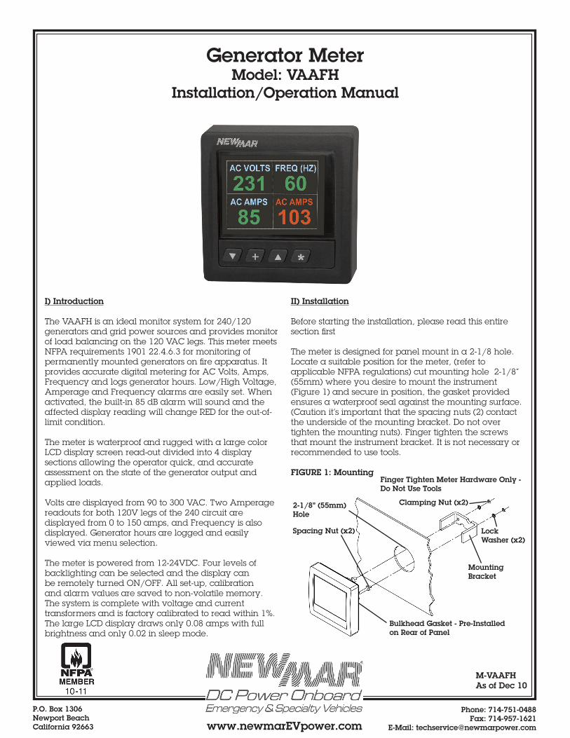
P.O. Box 1306 Newport Beach California 92663 Phone: 714-751-0488 Fax: 714-957-1621 E-Mail: [email protected] www.newmarEVpower.com I) Introduction The VAAFH is an ideal monitor system for 240/120 generators and grid power sources and provides monitor of load balancing on the 120 VAC legs. This meter meets NFPA requirements 1901 22.4.6.3 for monitoring of permanently mounted generators on fire apparatus. It provides accurate digital metering for AC Volts, Amps, Frequency and logs generator hours. Low/High Voltage, Amperage and Frequency alarms are easily set. When activated, the built-in 85 dB alarm will sound and the affected display reading will change RED for the out-of- limit condition. The meter is waterproof and rugged with a large color LCD display screen read-out divided into 4 display sections allowing the operator quick, and accurate assessment on the state of the generator output and applied loads. Volts are displayed from 90 to 300 VAC. Two Amperage readouts for both 120V legs of the 240 circuit are displayed from 0 to 150 amps, and Frequency is also displayed. Generator hours are logged and easily viewed via menu selection. The meter is powered from 12-24VDC. Four levels of backlighting can be selected and the display can be remotely turned ON/OFF. All set-up, calibration and alarm values are saved to non-volatile memory. The system is complete with voltage and current transformers and is factory calibrated to read within 1%. The large LCD display draws only 0.08 amps with full brightness and only 0.02 in sleep mode. II) Installation Before starting the installation, please read this entire section first The meter is designed for panel mount in a 2-1/8 hole. Locate a suitable position for the meter, (refer to applicable NFPA regulations) cut mounting hole 2-1/8” (55mm) where you desire to mount the instrument (Figure 1) and secure in position, the gasket provided ensures a waterproof seal against the mounting surface. (Caution it’s important that the spacing nuts (2) contact the underside of the mounting bracket. Do not over tighten the mounting nuts). Finger tighten the screws that mount the instrument bracket. It is not necessary or recommended to use tools. FIGURE 1: Mounting M-VAAFH As of Dec 10 Generator Meter Model: VAAFH Installation/Operation Manual Finger Tighten Meter Hardware Only - Do Not Use Tools Bulkhead Gasket - Pre-Installed on Rear of Panel Mounting Bracket 2-1/8” (55mm) Hole Spacing Nut (x2) Clamping Nut (x2) Lock Washer (x2)
Transcript of Generator Meter - Kussmaul Electronics · frequency needs calibration a frequency meter will be...
P.O. Box 1306Newport BeachCalifornia 92663
Phone: 714-751-0488 Fax: 714-957-1621
E-Mail: [email protected]
I) Introduction
The VAAFH is an ideal monitor system for 240/120 generators and grid power sources and provides monitor of load balancing on the 120 VAC legs. This meter meets NFPA requirements 1901 22.4.6.3 for monitoring of permanently mounted generators on fire apparatus. It provides accurate digital metering for AC Volts, Amps, Frequency and logs generator hours. Low/High Voltage, Amperage and Frequency alarms are easily set. When activated, the built-in 85 dB alarm will sound and the affected display reading will change RED for the out-of-limit condition.
The meter is waterproof and rugged with a large color LCD display screen read-out divided into 4 display sections allowing the operator quick, and accurate assessment on the state of the generator output and applied loads.
Volts are displayed from 90 to 300 VAC. Two Amperage readouts for both 120V legs of the 240 circuit are displayed from 0 to 150 amps, and Frequency is also displayed. Generator hours are logged and easily viewed via menu selection.
The meter is powered from 12-24VDC. Four levels of backlighting can be selected and the display can be remotely turned ON/OFF. All set-up, calibration and alarm values are saved to non-volatile memory. The system is complete with voltage and current transformers and is factory calibrated to read within 1%. The large LCD display draws only 0.08 amps with full brightness and only 0.02 in sleep mode.
II) Installation
Before starting the installation, please read this entire section first
The meter is designed for panel mount in a 2-1/8 hole. Locate a suitable position for the meter, (refer to applicable NFPA regulations) cut mounting hole 2-1/8” (55mm) where you desire to mount the instrument (Figure 1) and secure in position, the gasket provided ensures a waterproof seal against the mounting surface. (Caution it’s important that the spacing nuts (2) contact the underside of the mounting bracket. Do not over tighten the mounting nuts). Finger tighten the screws that mount the instrument bracket. It is not necessary or recommended to use tools.
FIGURE 1: Mounting
M-VAAFHAs of Dec 10
Generator MeterModel: VAAFH
Installation/Operation Manual
Finger Tighten Meter Hardware Only - Do Not Use Tools
Bulkhead Gasket - Pre-Installed on Rear of Panel
Mounting Bracket
2-1/8” (55mm) Hole
Spacing Nut (x2)
Clamping Nut (x2)
Lock Washer (x2)

P.O. Box 1306Newport BeachCalifornia 92663
Phone: 714-751-0488 Fax: 714-957-1621
E-Mail: [email protected]
Figure 2: Wiring Diagram
2
L1L1
L2L2
N NTo AC
Distribution Panel
120/240 VAC Source,
300 VAC Max
Input Power-12-24 VDC+Fuse at Source
Current Transformers
5
6
3’ Max.6
52’ - 2.5’Max.
Tie Wrap Wire Hold Down Point
3’ Interconnect Cable with Plug
Provided with Meter
Plug-in Connector
Interface Box
C.T. 1
C.T. 2
C.T
. 1
C.T
. 1
C.T
. 2
C.T
. 2
+ D
C
- DC
(+5
VD
C)
ALA
RM
N/U
VAC
VAC
Figure 3: Terminal ID Diagram
Plug-in Connector
See Figure 3 Below for Terminal I.D.

P.O. Box 1306Newport BeachCalifornia 92663
Phone: 714-751-0488 Fax: 714-957-1621
E-Mail: [email protected]
III) Wiring & Powering Up
The following wiring components are provided with the meter:
1 ea. Interface Box containing AC voltage transformer and board 2 ea. AC current transformers2 ea. Tie Wraps
1) Power Wiring (for operating the meter)The VAAFH is powered from a source of 9.5 to 33.0 VDC. Attach power wiring per diagram, see FIG. 2 & 3. Fuse at source
2) Monitor WiringThe meter receives voltage and amperage signals from the provided wiring interface box and current transformers. CAUTION: DO NOT APPLY RAW AC VOLTAGE OR CURRENT DIRECTLY TO THE METER, THIS WILL DESTROY THE METER. Attach the signal data wiring to the meter as shown in FIG. 2
3) Current Transformer WiringTwo C.T.’s are provided, each with 40” length two conductor (26 AWG) cable. Wire colors are black and yellow. The yellow and black wires can be connected to the Interface box PCB in either direction, there is no polarity for C.T. connection. Please disregard arrow on top of C.T., there is no current direction for the VAAFh installation. For new installations, we recommend passing the Line side cable of the current carrying source through the center opening in the C.T. (Dia.: .630”). For pre-wired installations, the C.T. donut hole can be opened to allow the C.T. to clamp over the cable. To open C.T. use a small slotted screwdriver; pry up both ends, lift up the non-secured end, release top from plastic latches, clamp over cable and push the two C.T. halves back together and snap the plastic latches shut
The VAAFH is designed to operate with the provided interface box. Locate the interface close enough for the VAAFH cable to reach (2’ to 2.5’). The box also needs to be located a maximum of 3’ from L1 & L2 main feeds for the current transformer leads to reach the Interface box.
4) Alarm Wiring (Optional)This terminal produces a +5 VDC signal (100mA max.) with reference to DC when an alarm condition is detected. Maintenance alarm does not affect +5 VDC alarm output. This +5 VDC signal is compatible with Newmar model DIR (optional), solid state relay which
can carry an AC or DC circuit up to 10 amps.
5) Powering UpOnce the meter wiring/installation is complete, double check DC power polarity and then connect 12, 24, or 32 VDC power to meter. It is normal for meter to take 20-30 seconds to start up before the display readings settle. Note: Display refreshes readings every 2 seconds.
IV) Menu Navigation & Calibration
A) Main Page
When the instrument is powered up it displays the “Main” page. The “Main” page displays: AC Volts, Frequency (HERTZ), AC AMPS #1, and AC AMPS #2. Values are displayed in GREEN if within acceptable alarm set limits or RED if out of limits condition exists.
From MAIN PAGE display:• Pressing the p key for ½ second (longer than a quick press but shorter than 2 seconds) will cause a white ALARM bell symbol to be displayed and enable the alarms.
• Pressing the q key for ½ second (longer than a quick press but shorter than 2 seconds) will disable the alarms and remove the white alarm bell symbol.
• Pressing the + key for ½ second (longer than a quick press but shorter than 2 seconds) will increment the backlight level through four different intensities.
B) Generator Hours Page
While in the Main page, a quick press of both p and * keys at the same time will bring up the Generator Hours page which includes: Total Generator Hours and Hours till Maintenance Required. This page will revert back to Main page after 10 seconds from the last key press. No access code required to view the Hours page. This page is for viewing of generator and service hours. There are no adjustments available on this page.
120V Screen 240V Screen
Current Transformer: Closed and Open
Secured EndPlastic Latches

P.O. Box 1306Newport BeachCalifornia 92663
Phone: 714-751-0488 Fax: 714-957-1621
E-Mail: [email protected]
The Main page is displayed ten seconds from entering the Generator/Maintenance screen or by quick pressing both the q and * keys at the same time.
C) Secured Access Pages
While in the Main page or Generator Hours page, a Quick press of the * key brings up the Security Access page and a default number 5000 is displayed in the ACCESS CODE box.
Use the p and q keys to scroll to the correct access code and press “ACCEPT” to enter that number (default ACCESS CODE is 1234). The longer you hold down the p or q key, the faster the scrolling of numbers. False entry results in Main Page being displayed. Entry of correct access code unlocks the instrument and brings up the following menu:
After security access has been granted and you return to the Main page, you have 60 seconds to re-enter the secured pages by quickly pressing the * key or youwill have to re-enter the security code. You may toggle between the Main page and secured pages without reentering the security code, but will need to re-enter it after 60 seconds from the last key press.
For each menu or sub-menu item the following is true: Pressing the q or p keys moves highlighted selection down or up. Pressing the QUIT (*) key returns you to the Main Page. Pressing the ACCEPT key selects the highlighted menu item. Pressing no key for 60 seconds returns you to the Main Page and locks the security access.
D) Alarms
Selecting the ALARMS menu brings up the following sub-menu:AC VOLTS HI (Adjustable from 90 to 300)AC VOLTS LO (Adjustable from 90 to 300)FREQUENCY HIGH (Adjustable from 30 to 100)FREQUENCY LO (Adjustable from 30 to 100)AC AMPS #1 HI (Adjustable from 0 to 150)AC AMPS #2 HI (Adjustable from 0 to 150)MAINTENANCE (Adjustable from 0 to 5000)f BACK (Returns to previous page)
Use the UP or DOWN button to move to the appropriate item then press the + (ACCEPT) key. Use the p or q keys to increase or decrease the number to the desired value then press the + (ACCEPT) key to set the value and return to the ALARMS menu or the * (QUIT) key to set the value and return to the Main page.
E) Calibration
Selecting the CALIBRATE menu brings up the following sub-menu:AC VOLTSFREQUENCYAC AMPS #1AC AMPS #2ZERO AC AMPS #1ZERO AC AMPS #2f BACK
To calibrate the VAAFH meter volts, Hz. and Amps, you will need a separate reference test meter, AC RMS voltage and current probe to measure AC RMS current. All reference meters should have an accuracy of 1% or better. Also you will need a stable voltage and load source. Load source can be lamps or heaters. NOTE: These loads may drift a little so always re verify measurements before adjusting calibration value. Calibration should be performed after installation is complete.
3

P.O. Box 1306Newport BeachCalifornia 92663
Phone: 714-751-0488 Fax: 714-957-1621
E-Mail: [email protected]
Remove the cover from the VAAFH interface box to gain access to its terminal block. This will be needed to measure AC voltage. WARNING: High voltage is present at terminal block.
AC VoltsApply AC mains and DC power to circuit. Do not apply a load at this time. Measure the AC RMS voltage at TB1 terminals 9 and 10. Go to the sub-menu of the AC VOLTS calibration menu and adjust the value up or down using the up or down buttons so it matches the measured reading then press the * (accept) button when done.
FrequencyFrequency does not typically need calibration. If frequency needs calibration a frequency meter will be needed. Measure the frequency at TB1 terminals 9&10. Got to the sub-menu of the calibration frequency menu and adjust the value up or down using the up or down buttons then press the * (accept) button when done. WARNING: High voltage is present at terminal block.
Zeroing AC Amps #1 and #2Apply AC mains and DC power to circuit. Do not apply any load at this time. Go to the sub-menu of the calibrate menu and select either the ZERO AC AMPS #1 or #2. Zeroing amps should be done before calibrating AC Amps.
AC Amps #1 and #2Apply AC mains and DC power to circuit and apply a load. Measure the AC RMS current through the load wires (#1 or #2). Go to the sub-menu of the AC AMPS (#1 or #2) calibration menu and adjust the value up or down using the up or down buttons so it matches the measured reading then press the * (accept) button when done.
ATTENTION: Calibration should only be performed by qualified personnel. Published accuracies are based on proper calibration in conjunction with the 773-5385-0 meter interface. If it is determined that calibration is needed, first ensure all sense transformers are terminated properly to the meter prior to calibrating.
If the Amps show a positive number when zero amps are being passed through the current transformer it is possible to automatically zero the amps #1 or amps #2 from the “Calibrate” page. At low values of CT voltage there is a slight interaction between the Zero Amps and the
Calibrate Amps and it may require you to re-calibrate slightly after you have used the Zero Amps feature.
If the user accidentally zeros the amps #1 or amps #2 while positive amps are actually being passed through the current transformer, the meter will no longer display amps correctly and the amps offset will have to be cleared. This is done by holding the q key for more than 10 seconds while the meter is displaying “NO YES NO NO”
on the “Setup”g”Reset Alarm Bell” page. This feature has been hidden to make it difficult to do by accident.
Trying to calibrate the instrument when in simulate mode will be problematic since the simulated inputs are constantly changing.
F) Set-Up
Selecting the SETUP menu brings up the following sub-menu:
ACCESS CODEZERO GENERATOR HOURSMAINTENANCE ALARMCURRENT p VALUERESET ALARM BELLf BACK
ACCESS CODE fLets the user change the access codeZERO GENERATOR HOURS fWill ZERO the generator hours (after asking if sure)MAINTENANCE ALARM f User can set the Maintenance alarm valueCURRENT p VALUE f User can set the current value to count down from (Hours) RESET ALARM BELL f Remove RED alarm bell symbol from Main Page (maintenance alarm) and Resets “CURRENT p VALUE” to “MAINTENANCE ALARM” valuef BACK
A) Access Code Setting
If no key has been pressed for 60 seconds from any of the menus or submenus, the instrument will revert to displaying the Main Page.
The ACCESS CODE is required to access alarm settings, instrument setup and calibration menus. Set the ACCESS CODE to a number from 0000 to 9999 by using the p or q keys then press the + key to accept. The factory default is set to 1234.
If the ACCESS CODE is ever forgotten, the instrument can be reset back to factory default (see “Reset to Default”). Caution: Resetting to factory default will reset all alarm and calibration settings as well.
4

P.O. Box 1306Newport BeachCalifornia 92663
Phone: 714-751-0488 Fax: 714-957-1621
E-Mail: [email protected]
B) Zero Generator Hours SettingSelect this to set the TOTAL GENERATOR HOURS to zero either for new generator installs or after a generator has been replaced.
C) Maintenance Alarm SettingThis sets the alarm interval for the RED maintenance indicator bell.
Setting the MAINTENANCE ALARM value to zero will disable the maintenance alarm. The RED bell will not be displayed and the current maintenance alarm value will be set to zero.
CURRENT p VALUEThis is the hours remaining before maintenance alarm. Note: This value is set to “maintenance alarm” value when you do reset alarm bell
D) Details DisplaySelecting the DETAILS menu brings up an information page that displays:SERIAL NUMBER (YYMMDDnnn)ACCESS CODE nnnnINSTRUMENT ON HOURSAC VOLTS HI AND LO ALARM VALUESFREQUENCY HI AND LO ALARM VALUESAMPS #1 HI ALARM VALUEAMPS #2 HI ALARM VALUEGENERATOR HOURSMAINTENANCE ALARM VALUEHOURS TO GO TILL MAINTENANCE IS REQUIRED
E) AboutSelecting the ABOUT menu brings up an information page that displaysSoftware Version (S/W)Hardware Version (H/W)NEWMAR web page
V) Reset to Factory Default
Holding down the q, + and p keys on power-up will bring up a menu that allows the user to reset the instrument back to factory defaults. The calibration and alarm values will all be set to nominal and the instrument will have to be recalibrated. The security code well reset to default 1234.
On the CALIBRATE submenu the q and p buttons are used to calibrate the selected value (such as FREQUENCY) and the + key accepts that value. Pressing the * key quits the menu system and causes the Main Page to be displayed.
VI) Specifications
Power Supply: 9.50 to 33.00 VDC, @ 100mAOperating Temperature: 32° to 122° F (0° to 50° C) Size: 4.3” x 4.3” x 3.5” deep (110 x 110 x 89 mm). Display Data:
AC Volts: 90-300 VAC AC Amps: 0-150 ampsFrequency: 30 to 100 Hz.Hour Meter: 99,999.9 Hrs.
Resolution: 1 VAC, 1 amp, 1hz.Accuracy: Volts: 1% +/-1 digit
Amps: 2% +/-1 digitFrequency: .5% Hours: .5%
Supplied Transducers: Voltage (1 each) and Current transformers (2 each)Alarms: High/Low Voltage, High & Low Frequency, High Amps
5