Generator and Interconnection Protection REG615 Application Manual
156
Relion ® 615 series Generator and Interconnection Protection REG615 Application Manual
Transcript of Generator and Interconnection Protection REG615 Application Manual

Relion® 615 series
Generator and Interconnection ProtectionREG615Application Manual


Document ID: 1MRS758272Issued: 2016-05-20
Revision: AProduct version: 5.0 FP1
© Copyright 2016 ABB. All rights reserved

Copyright
This document and parts thereof must not be reproduced or copied without writtenpermission from ABB, and the contents thereof must not be imparted to a third party,nor used for any unauthorized purpose.
The software or hardware described in this document is furnished under a license andmay be used, copied, or disclosed only in accordance with the terms of such license.
TrademarksABB and Relion are registered trademarks of the ABB Group. All other brand orproduct names mentioned in this document may be trademarks or registeredtrademarks of their respective holders.
WarrantyPlease inquire about the terms of warranty from your nearest ABB representative.
http://www.abb.com/substationautomation

Disclaimer
The data, examples and diagrams in this manual are included solely for the concept orproduct description and are not to be deemed as a statement of guaranteed properties.All persons responsible for applying the equipment addressed in this manual mustsatisfy themselves that each intended application is suitable and acceptable, includingthat any applicable safety or other operational requirements are complied with. Inparticular, any risks in applications where a system failure and/or product failurewould create a risk for harm to property or persons (including but not limited topersonal injuries or death) shall be the sole responsibility of the person or entityapplying the equipment, and those so responsible are hereby requested to ensure thatall measures are taken to exclude or mitigate such risks.
This product has been designed to be connected and communicate data andinformation via a network interface which should be connected to a secure network.It is the sole responsibility of the person or entity responsible for networkadministration to ensure a secure connection to the network and to take the necessarymeasures (such as, but not limited to, installation of firewalls, application ofauthentication measures, encryption of data, installation of anti virus programs, etc.)to protect the product and the network, its system and interface included, against anykind of security breaches, unauthorized access, interference, intrusion, leakage and/ortheft of data or information. ABB is not liable for any such damages and/or losses.
This document has been carefully checked by ABB but deviations cannot becompletely ruled out. In case any errors are detected, the reader is kindly requested tonotify the manufacturer. Other than under explicit contractual commitments, in noevent shall ABB be responsible or liable for any loss or damage resulting from the useof this manual or the application of the equipment.

Conformity
This product complies with the directive of the Council of the European Communitieson the approximation of the laws of the Member States relating to electromagneticcompatibility (EMC Directive 2004/108/EC) and concerning electrical equipment foruse within specified voltage limits (Low-voltage directive 2006/95/EC). Thisconformity is the result of tests conducted by ABB in accordance with the productstandard EN 60255-26 for the EMC directive, and with the product standards EN60255-1 and EN 60255-27 for the low voltage directive. The product is designed inaccordance with the international standards of the IEC 60255 series.

Table of contents
Section 1 Introduction.......................................................................5This manual........................................................................................ 5Intended audience.............................................................................. 5Product documentation.......................................................................6
Product documentation set............................................................6Document revision history............................................................. 6Related documentation..................................................................7
Symbols and conventions...................................................................7Symbols.........................................................................................7Document conventions..................................................................8Functions, codes and symbols...................................................... 8
Section 2 REG615 overview.......................................................... 13Overview...........................................................................................13
Product version history................................................................13PCM600 and relay connectivity package version........................13
Operation functionality......................................................................14Optional functions........................................................................14
Physical hardware............................................................................ 14Local HMI......................................................................................... 16
Display.........................................................................................17LEDs............................................................................................18Keypad........................................................................................ 18
Web HMI...........................................................................................19Authorization.....................................................................................20
Audit trail......................................................................................21Communication.................................................................................23
Self-healing Ethernet ring............................................................24Ethernet redundancy................................................................... 25Process bus.................................................................................27Secure communication................................................................29
Section 3 REG615 standard configurations................................... 31Standard configurations....................................................................31
Addition of control functions for primary devices and the useof binary inputs and outputs........................................................ 33
Connection diagrams........................................................................34Standard configuration A.................................................................. 37
Applications................................................................................. 37Functions.....................................................................................38
Table of contents
REG615 1Application Manual

Default I/O connections.......................................................... 38Default disturbance recorder settings.....................................40
Functional diagrams.................................................................... 42Functional diagrams for protection......................................... 43Functional diagrams for disturbance recorder........................53Functional diagrams for condition monitoring.........................54Functional diagrams for control and interlocking....................56Functional diagram for measurement functions..................... 59Functional diagrams for IOs and alarm LEDs........................ 62Functional diagram for other timer logics............................... 65Other functions....................................................................... 66
Standard configuration C..................................................................66Applications................................................................................. 66Functions.....................................................................................67
Default I/O connections.......................................................... 68Default disturbance recorder settings.....................................69
Functional diagrams.................................................................... 72Functional diagrams for protection......................................... 72Functional diagrams for disturbance recorder........................86Functional diagrams for condition monitoring.........................87Functional diagrams for control and interlocking....................89Functional diagram for measurement functions..................... 91Functional diagrams for IOs and alarm LEDs........................ 94Functional diagram for other timer logics............................... 98Other functions..................................................................... 100
Standard configuration D................................................................100Applications............................................................................... 100Functions...................................................................................101
Default I/O connections........................................................ 101Default disturbance recorder settings...................................103
Functional diagrams.................................................................. 105Functional diagrams for protection....................................... 106Functional diagrams for disturbance recorder......................117Functional diagrams for condition monitoring.......................118Functional diagrams for control and interlocking..................120Functional diagram for measurement functions................... 122Functional diagrams for IOs and alarm LEDs...................... 125Functional diagram for other timer logics............................. 129Other functions..................................................................... 130
Section 4 Requirements for measurement transformers..............133Current transformers...................................................................... 133
Current transformer requirements for non-directionalovercurrent protection................................................................133
Table of contents
2 REG615Application Manual

Current transformer accuracy class and accuracy limitfactor.................................................................................... 133Non-directional overcurrent protection................................. 134Example for non-directional overcurrent protection..............135
Section 5 IED physical connections............................................. 137Inputs..............................................................................................137
Energizing inputs.......................................................................137Phase currents..................................................................... 137Residual current................................................................... 137Phase voltages.....................................................................137Residual voltage...................................................................138
Auxiliary supply voltage input.................................................... 138Binary inputs..............................................................................138Optional light sensor inputs....................................................... 140
Outputs........................................................................................... 140Outputs for tripping and controlling............................................140Outputs for signalling.................................................................141IRF.............................................................................................142
Section 6 Glossary....................................................................... 143
Table of contents
REG615 3Application Manual

4
Section 1 Introduction
1.1 This manual
The application manual contains application descriptions and setting guidelinessorted per function. The manual can be used to find out when and for what purpose atypical protection function can be used. The manual can also be used when calculatingsettings.
1.2 Intended audience
This manual addresses the protection and control engineer responsible for planning,pre-engineering and engineering.
The protection and control engineer must be experienced in electrical powerengineering and have knowledge of related technology, such as protection schemesand principles.
1MRS758272 A Section 1Introduction
REG615 5Application Manual

1.3 Product documentation
1.3.1 Product documentation set
Pla
nnin
g &
pu
rcha
se
Eng
inee
ring
Inst
alla
tion
Com
mis
sion
ing
Ope
ratio
n
Mai
nten
ance
Dec
omm
issi
onin
g,
dein
stal
latio
n &
dis
posa
l
Quick start guideQuick installation guideBrochureProduct guideOperation manualInstallation manualConnection diagramEngineering manualTechnical manualApplication manualCommunication protocol manualIEC 61850 engineering guidePoint list manualCyber security deployment guideline
GUID-12DC16B2-2DC1-48DF-8734-0C8B7116124C V2 EN
Figure 1: The intended use of documents during the product life cycle
Product series- and product-specific manuals can be downloadedfrom the ABB Web site http://www.abb.com/relion.
1.3.2 Document revision historyDocument revision/date Product version HistoryA/2016-05-20 5.0 FP1 First release
Download the latest documents from the ABB Web sitehttp://www.abb.com/substationautomation.
Section 1 1MRS758272 AIntroduction
6 REG615Application Manual

1.3.3 Related documentationName of the document Document IDModbus Communication Protocol Manual 1MRS756468
DNP3 Communication Protocol Manual 1MRS756709
IEC 60870-5-103 Communication Protocol Manual 1MRS756710
IEC 61850 Engineering Guide 1MRS756475
Engineering Manual 1MRS757121
Installation Manual 1MRS756375
Operation Manual 1MRS756708
Technical Manual 1MRS756887
Cyber Security Deployment Guideline 1MRS758280
1.4 Symbols and conventions
1.4.1 Symbols
The electrical warning icon indicates the presence of a hazard whichcould result in electrical shock.
The warning icon indicates the presence of a hazard which couldresult in personal injury.
The caution icon indicates important information or warning relatedto the concept discussed in the text. It might indicate the presence ofa hazard which could result in corruption of software or damage toequipment or property.
The information icon alerts the reader of important facts andconditions.
The tip icon indicates advice on, for example, how to design yourproject or how to use a certain function.
Although warning hazards are related to personal injury, it is necessary to understandthat under certain operational conditions, operation of damaged equipment may result
1MRS758272 A Section 1Introduction
REG615 7Application Manual

in degraded process performance leading to personal injury or death. Therefore,comply fully with all warning and caution notices.
1.4.2 Document conventions
A particular convention may not be used in this manual.
• Abbreviations and acronyms are spelled out in the glossary. The glossary alsocontains definitions of important terms.
• Push button navigation in the LHMI menu structure is presented by using thepush button icons.To navigate between the options, use and .
• Menu paths are presented in bold.Select Main menu/Settings.
• LHMI messages are shown in Courier font.To save the changes in nonvolatile memory, select Yes and press .
• Parameter names are shown in italics.The function can be enabled and disabled with the Operation setting.
• Parameter values are indicated with quotation marks.The corresponding parameter values are "On" and "Off".
• Input/output messages and monitored data names are shown in Courier font.When the function starts, the START output is set to TRUE.
• This document assumes that the parameter setting visibility is "Advanced".
1.4.3 Functions, codes and symbolsTable 1: Functions included in the relay
Function IEC 61850 IEC 60617 IEC-ANSIProtection
Three-phase non-directionalovercurrent protection, low stage
PHLPTOC1 3I> (1) 51P-1 (1)
Three-phase non-directionalovercurrent protection, high stage
PHHPTOC1 3I>> (1) 51P-2 (1)
Three-phase non-directionalovercurrent protection,instantaneous stage
PHIPTOC1 3I>>> (1) 50P/51P (1)
Three-phase directionalovercurrent protection, low stage
DPHLPDOC1 3I> -> (1) 67-1 (1)
DPHLPDOC2 3I> -> (2) 67-1 (2)
Three-phase directionalovercurrent protection, high stage
DPHHPDOC1 3I>> -> (1) 67-2 (1)
Three-phase voltage-dependentovercurrent protection
PHPVOC1 3I(U)> (1) 51V (1)
Non-directional earth-faultprotection, high stage
EFHPTOC1 Io>> (1) 51N-2 (1)
Directional earth-fault protection,low stage
DEFLPDEF1 Io> -> (1) 67N-1 (1)
DEFLPDEF2 Io> -> (2) 67N-1 (2)
Table continues on next page
Section 1 1MRS758272 AIntroduction
8 REG615Application Manual

Function IEC 61850 IEC 60617 IEC-ANSIDirectional earth-fault protection,high stage
DEFHPDEF1 Io>> -> (1) 67N-2 (1)
Transient/intermittent earth-faultprotection
INTRPTEF1 Io> -> IEF (1) 67NIEF (1)
Negative-sequence overcurrentprotection
NSPTOC1 I2> (1) 46 (1)
NSPTOC2 I2> (2) 46 (2)
Negative-sequence overcurrentprotection for machines
MNSPTOC1 I2>M (1) 46M (1)
MNSPTOC2 I2>M (2) 46M (2)
Residual overvoltage protection ROVPTOV1 Uo> (1) 59G (1)
ROVPTOV2 Uo> (2) 59G (2)
Three-phase undervoltageprotection
PHPTUV1 3U< (1) 27 (1)
PHPTUV2 3U< (2) 27 (2)
Three-phase overvoltageprotection
PHPTOV1 3U> (1) 59 (1)
PHPTOV2 3U> (2) 59 (2)
Positive-sequence undervoltageprotection
PSPTUV1 U1< (1) 47U+ (1)
PSPTUV2 U1< (2) 47U+ (2)
Negative-sequence overvoltageprotection
NSPTOV1 U2> (1) 47O- (1)
NSPTOV2 U2> (2) 47O- (2)
Frequency protection FRPFRQ1 f>/f<,df/dt (1) 81 (1)
FRPFRQ2 f>/f<,df/dt (2) 81 (2)
FRPFRQ3 f>/f<,df/dt (3) 81 (3)
FRPFRQ4 f>/f<,df/dt (4) 81 (4)
FRPFRQ5 f>/f<,df/dt (5) 81 (5)
FRPFRQ6 f>/f<,df/dt (6) 81 (6)
Overexcitation protection OEPVPH1 U/f> (1) 24 (1)
Three-phase thermal protection forfeeders, cables and distributiontransformers
T1PTTR1 3Ith>F (1) 49F (1)
Three-phase thermal overloadprotection, two time constants
T2PTTR1 3Ith>T/G/C (1) 49T/G/C (1)
Circuit breaker failure protection CCBRBRF1 3I>/Io>BF (1) 51BF/51NBF (1)
Three-phase inrush detector INRPHAR1 3I2f> (1) 68 (1)
Master trip TRPPTRC1 Master Trip (1) 94/86 (1)
TRPPTRC2 Master Trip (2) 94/86 (2)
TRPPTRC3 Master Trip (3) 94/86 (3)
TRPPTRC4 Master Trip (4) 94/86 (4)
TRPPTRC5 Master Trip (5) 94/86 (5)
TRPPTRC6 Master Trip (6) 94/86 (6)
Arc protection ARCSARC1 ARC (1) 50L/50NL (1)
ARCSARC2 ARC (2) 50L/50NL (2)
ARCSARC3 ARC (3) 50L/50NL (3)
Table continues on next page
1MRS758272 A Section 1Introduction
REG615 9Application Manual

Function IEC 61850 IEC 60617 IEC-ANSIMultipurpose protection MAPGAPC1 MAP (1) MAP (1)
MAPGAPC2 MAP (2) MAP (2)
MAPGAPC3 MAP (3) MAP (3)
MAPGAPC4 MAP (4) MAP (4)
MAPGAPC5 MAP (5) MAP (5)
MAPGAPC6 MAP (6) MAP (6)
MAPGAPC7 MAP (7) MAP (7)
MAPGAPC8 MAP (8) MAP (8)
MAPGAPC9 MAP (9) MAP (9)
MAPGAPC10 MAP (10) MAP (10)
MAPGAPC11 MAP (11) MAP (11)
MAPGAPC12 MAP (12) MAP (12)
MAPGAPC13 MAP (13) MAP (13)
MAPGAPC14 MAP (14) MAP (14)
MAPGAPC15 MAP (15) MAP (15)
MAPGAPC16 MAP (16) MAP (16)
MAPGAPC17 MAP (17) MAP (17)
MAPGAPC18 MAP (18) MAP (18)
Stabilized and instantaneousdifferential protection for machines
MPDIF1 3dI>G/M (1) 87G/M (1)
Third harmonic-based stator earth-fault protection
H3EFPSEF1 dUo>/Uo3H (1) 27/59THD (1)
Underpower protection DUPPDPR1 P< (1) 32U (1)
DUPPDPR2 P< (2) 32U (2)
Reverse power/directionaloverpower protection
DOPPDPR1 P>/Q> (1) 32R/32O (1)
DOPPDPR2 P>/Q> (2) 32R/32O (2)
DOPPDPR3 P>/Q> (3) 32R/32O (3)
Three-phase underexcitationprotection
UEXPDIS1 X< (1) 40 (1)
Three-phase underimpedanceprotection
UZPDIS1 Z<G (1) 21G (1)
Out-of-step protection OOSRPSB1 OOS (1) 78 (1)
Interconnection functions
Directional reactive powerundervoltage protection
DQPTUV1 Q> ->,3U< (1) 32Q,27 (1)
Low-voltage ride-throughprotection
LVRTPTUV1 U<RT (1) 27RT (1)
LVRTPTUV2 U<RT (2) 27RT (2)
LVRTPTUV3 U<RT (3) 27RT (3)
Voltage vector shift protection VVSPPAM1 VS (1) 78V (1)
Power quality
Current total demand distortion CMHAI1 PQM3I (1) PQM3I (1)
Table continues on next page
Section 1 1MRS758272 AIntroduction
10 REG615Application Manual

Function IEC 61850 IEC 60617 IEC-ANSIVoltage total harmonic distortion VMHAI1 PQM3U (1) PQM3V (1)
Voltage variation PHQVVR1 PQMU (1) PQMV (1)
Voltage unbalance VSQVUB1 PQUUB (1) PQVUB (1)
Control
Circuit-breaker control CBXCBR1 I <-> O CB (1) I <-> O CB (1)
Disconnector control DCXSWI1 I <-> O DCC (1) I <-> O DCC (1)
DCXSWI2 I <-> O DCC (2) I <-> O DCC (2)
Earthing switch control ESXSWI1 I <-> O ESC (1) I <-> O ESC (1)
Disconnector position indication DCSXSWI1 I <-> O DC (1) I <-> O DC (1)
DCSXSWI2 I <-> O DC (2) I <-> O DC (2)
DCSXSWI3 I <-> O DC (3) I <-> O DC (3)
Earthing switch indication ESSXSWI1 I <-> O ES (1) I <-> O ES (1)
ESSXSWI2 I <-> O ES (2) I <-> O ES (2)
Synchronism and energizing check SECRSYN1 SYNC (1) 25 (1)
Condition monitoring and supervision
Circuit-breaker conditionmonitoring
SSCBR1 CBCM (1) CBCM (1)
Trip circuit supervision TCSSCBR1 TCS (1) TCM (1)
TCSSCBR2 TCS (2) TCM (2)
Current circuit supervision CCSPVC1 MCS 3I (1) MCS 3I (1)
Fuse failure supervision SEQSPVC1 FUSEF (1) 60 (1)
Runtime counter for machines anddevices
MDSOPT1 OPTS (1) OPTM (1)
Measurement
Disturbance recorder RDRE1 DR (1) DFR (1)
Load profile record LDPRLRC1 LOADPROF (1) LOADPROF (1)
Fault record FLTRFRC1 FAULTREC (1) FAULTREC (1)
Three-phase current measurement CMMXU1 3I (1) 3I (1)
CMMXU2 3I (2) 3I (2)
Sequence current measurement CSMSQI1 I1, I2, I0 (1) I1, I2, I0 (1)
Residual current measurement RESCMMXU1 Io (1) In (1)
Three-phase voltage measurement VMMXU1 3U (1) 3V (1)
VMMXU2 3U (2) 3V (2)
Residual voltage measurement RESVMMXU1 Uo (1) Vn (1)
RESVMMXU2 Uo (2) Vn (2)
Sequence voltage measurement VSMSQI1 U1, U2, U0 (1) V1, V2, V0 (1)
Three-phase power and energymeasurement
PEMMXU1 P, E (1) P, E (1)
RTD/mA measurement XRGGIO130 X130 (RTD) (1) X130 (RTD) (1)
Frequency measurement FMMXU1 f (1) f (1)
Table continues on next page
1MRS758272 A Section 1Introduction
REG615 11Application Manual
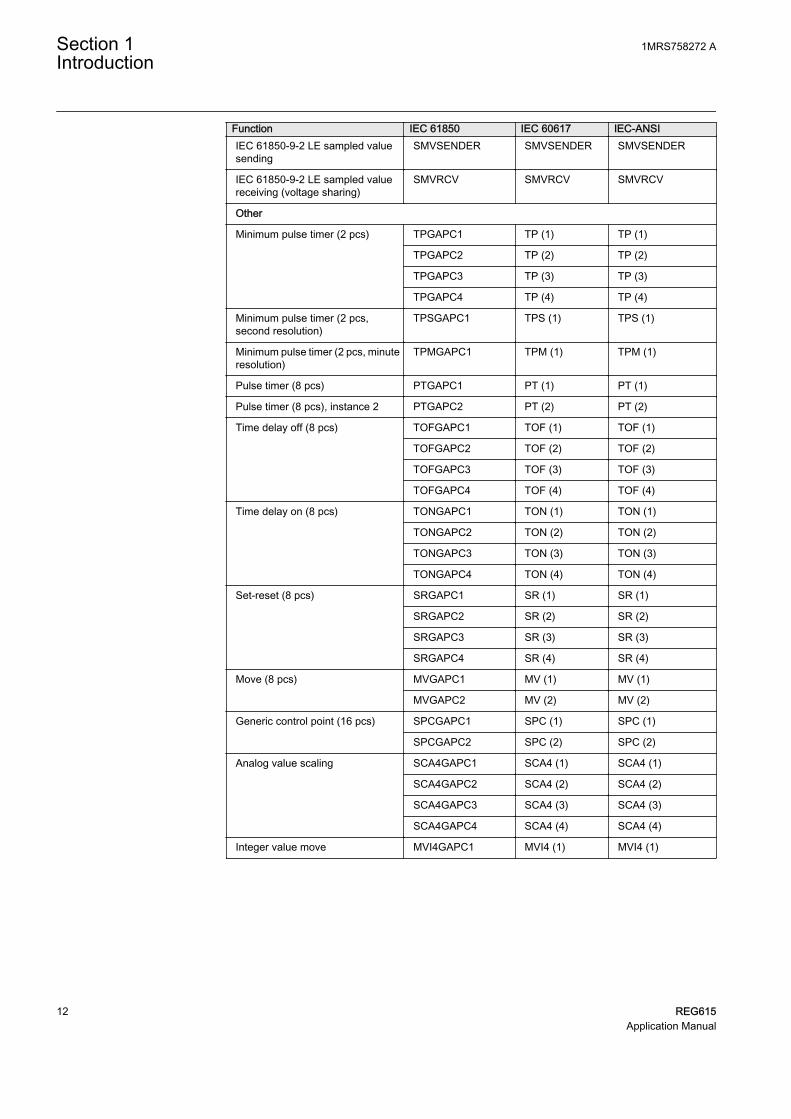
Function IEC 61850 IEC 60617 IEC-ANSIIEC 61850-9-2 LE sampled valuesending
SMVSENDER SMVSENDER SMVSENDER
IEC 61850-9-2 LE sampled valuereceiving (voltage sharing)
SMVRCV SMVRCV SMVRCV
Other
Minimum pulse timer (2 pcs) TPGAPC1 TP (1) TP (1)
TPGAPC2 TP (2) TP (2)
TPGAPC3 TP (3) TP (3)
TPGAPC4 TP (4) TP (4)
Minimum pulse timer (2 pcs,second resolution)
TPSGAPC1 TPS (1) TPS (1)
Minimum pulse timer (2 pcs, minuteresolution)
TPMGAPC1 TPM (1) TPM (1)
Pulse timer (8 pcs) PTGAPC1 PT (1) PT (1)
Pulse timer (8 pcs), instance 2 PTGAPC2 PT (2) PT (2)
Time delay off (8 pcs) TOFGAPC1 TOF (1) TOF (1)
TOFGAPC2 TOF (2) TOF (2)
TOFGAPC3 TOF (3) TOF (3)
TOFGAPC4 TOF (4) TOF (4)
Time delay on (8 pcs) TONGAPC1 TON (1) TON (1)
TONGAPC2 TON (2) TON (2)
TONGAPC3 TON (3) TON (3)
TONGAPC4 TON (4) TON (4)
Set-reset (8 pcs) SRGAPC1 SR (1) SR (1)
SRGAPC2 SR (2) SR (2)
SRGAPC3 SR (3) SR (3)
SRGAPC4 SR (4) SR (4)
Move (8 pcs) MVGAPC1 MV (1) MV (1)
MVGAPC2 MV (2) MV (2)
Generic control point (16 pcs) SPCGAPC1 SPC (1) SPC (1)
SPCGAPC2 SPC (2) SPC (2)
Analog value scaling SCA4GAPC1 SCA4 (1) SCA4 (1)
SCA4GAPC2 SCA4 (2) SCA4 (2)
SCA4GAPC3 SCA4 (3) SCA4 (3)
SCA4GAPC4 SCA4 (4) SCA4 (4)
Integer value move MVI4GAPC1 MVI4 (1) MVI4 (1)
Section 1 1MRS758272 AIntroduction
12 REG615Application Manual

Section 2 REG615 overview
2.1 Overview
REG615 is a dedicated generator and interconnection protection relay designed forthe different power generation applications. REG615 is available in three standardconfigurations denoted A, C and D. Standard configuration A is intended for theinterconnection protection, control, measurement and supervision of the commonpoint of coupling distributed power generation into the utility network. Standardconfigurations C and D are designed for the protection, control, measurement andsupervision of small or medium size generators used in diesel, gas, hydroelectric,combined heat and power (CHP), and steam power plants. REG615 is a member ofABB’s Relion® product family and part of its 615 protection and control productseries. The 615 series protection relays are characterized by their compactness andwithdrawable unit design.
Re-engineered from the ground up, the 615 series has been designed to unleash the fullpotential of the IEC 61850 standard for communication and interoperability betweensubstation automation devices. Once the standard configuration relay has been giventhe application-specific settings, it can directly be put into service.
The generator protection relay provides main protection for small size powergenerators. The generator protection relay is also used as back-up protection formedium size generators in power applications, where an independent and redundantprotection system is required. The interconnection protection relay provides mainprotection fulfilling the grid codes to connect distributed generation with the powergrid.
The 615 series relays support a range of communication protocols including IEC61850 with Edition 2 support, process bus according to IEC 61850-9-2 LE, IEC60870-5-103, Modbus® and DNP3. Profibus DPV1 communication protocol issupported by using the protocol converter SPA-ZC 302.
2.1.1 Product version historyProduct version Product history5.0 FP1 Product released
2.1.2 PCM600 and relay connectivity package version
• Protection and Control IED Manager PCM600 2.6 (Rollup 20150626) or later• REG615 Connectivity Package Ver.5.1 or later
1MRS758272 A Section 2REG615 overview
REG615 13Application Manual

• Parameter Setting• Signal Monitoring• Event Viewer• Disturbance Handling• Application Configuration• Signal Matrix• Graphical Display Editor• Communication Management• IED User Management• IED Compare• Firmware Update• Fault Record tool• Load Record Profile• Lifecycle Traceability• Configuration Wizard• Label Printing• IEC 61850 Configuration• IED Configuration Migration
Download connectivity packages from the ABB Web sitehttp://www.abb.com/substationautomation or directly with theUpdate Manager in PCM600.
2.2 Operation functionality
2.2.1 Optional functions
• Arc protection• Modbus TCP/IP or RTU/ASCII• IEC 60870-5-103• DNP3 TCP/IP or serial• Power quality functions• RTD/mA measurement• IEC 61850-9-2 LE• IEEE 1588 v2 time synchronization
2.3 Physical hardware
The protection relay consists of two main parts: plug-in unit and case. The contentdepends on the ordered functionality.
Section 2 1MRS758272 AREG615 overview
14 REG615Application Manual

Table 2: Plug-in unit and case
Main Slot ID Content optionsPlug-inunit
- HMI Small (5 lines, 20 characters)Large (10 lines, 20 characters) with SLD
Small Chinese (3 lines, 8 or more characters)Large Chinese (7 lines, 8 or more characters) withSLD
X100 Auxiliary power/BOmodule
48-250V DC/100-240 V AC; or 24-60 V DC2 normally-open PO contacts1 change-over SO contact1 normally open SO contact2 double-pole PO contacts with TCS1 dedicated internal fault output contact
X110 BIO module 8 binary inputs4 SO contacts
8 binary inputs3 HSO contacts
X120 AI/BI module Only with configurations A and C:3 phase current inputs (1/5 A)1 residual current input (1/5 A or 0.2/1 A)1)
4 binary inputs
Only with configuration D:6 phase current inputs (1/5 A)1 residual current input (1/5 A or 0.2/1 A)1)
Case X130 AI/BI module 3 phase voltage inputs (60-210 V)1 residual voltage input (60-210 V)4 binary inputsAdditionally with configurations A and D:1 reference voltage input for SECRSYN1 (60-210 V)Additionally with configuration C:1 residual voltage input for H3EFPSEF1 (60-210 V)
AI/RTD/mA module 3 phase voltage inputs (60-210 V)1 residual voltage input (60-210 V)1 generic mA inputs2 RTD sensor inputsAdditionally with configurations A and D:1 reference voltage input for SECRSYN1 (60-210 V)Additionally with configuration C:1 residual voltage input for H3EFPSEF1 (60-210 V)
X000 Optional communicationmodule
See the technical manual for details about differenttypes of communication modules.
1) The 0.2/1 A input is normally used in applications requiring sensitive earth-fault protection and featuringcore-balance current transformers.
Rated values of the current and voltage inputs are basic setting parameters of theprotection relay. The binary input thresholds are selectable within the range 16…176V DC by adjusting the binary input setting parameters.
The connection diagrams of different hardware modules are presented in this manual.
See the installation manual for more information about the case andthe plug-in unit.
1MRS758272 A Section 2REG615 overview
REG615 15Application Manual

Table 3: Input/output overview
Std. conf. Order code digit Analog channels Binary channels 5-6 7-8 CT VT BI BO RTD mA
A
AE / AF
AG 4 5 16 4 PO + 6SO
- -
FC 4 5 16 4 PO + 2SO + 3HSO
- -
FE / FF
AD 4 5 12 4 PO + 6SO
2 1
FE 4 5 12 4 PO + 2SO + 3HSO
2 1
C
AE / AF
AG 4 5 16 4 PO + 6SO
- -
FC 4 5 16 4 PO + 2SO + 3HSO
- -
FE / FF
AD 4 5 12 4 PO + 6SO
2 1
FE 4 5 12 4 PO + 2SO + 3HSO
2 1
D
BC / BD
AD 7 5 12 4 PO + 6SO
- -
FE 7 5 12 4 PO + 2SO + 3HSO
- -
BE / BF
BA 7 5 8 4 PO + 6SO
2 1
FD 7 5 8 4 PO + 2SO + 3HSO
2 1
2.4 Local HMI
The LHMI is used for setting, monitoring and controlling the protection relay. TheLHMI comprises the display, buttons, LED indicators and communication port.
Section 2 1MRS758272 AREG615 overview
16 REG615Application Manual
REF615
Overcurrent
Dir. earth-fault
Voltage protection
Phase unbalance
Thermal overload
Breaker failure
Disturb. rec. Triggered
CB condition monitoring
Supervision
Arc detected
Autoreclose shot in progr.
A070704 V4 EN
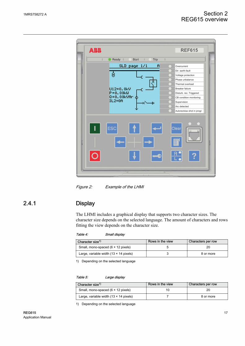
Figure 2: Example of the LHMI
2.4.1 Display
The LHMI includes a graphical display that supports two character sizes. Thecharacter size depends on the selected language. The amount of characters and rowsfitting the view depends on the character size.
Table 4: Small display
Character size1) Rows in the view Characters per row
Small, mono-spaced (6 × 12 pixels) 5 20
Large, variable width (13 × 14 pixels) 3 8 or more
1) Depending on the selected language
Table 5: Large display
Character size1) Rows in the view Characters per row
Small, mono-spaced (6 × 12 pixels) 10 20
Large, variable width (13 × 14 pixels) 7 8 or more
1) Depending on the selected language
1MRS758272 A Section 2REG615 overview
REG615 17Application Manual

The display view is divided into four basic areas.
1 2
3 4A070705 V3 EN
Figure 3: Display layout
1 Header
2 Icon
3 Content
4 Scroll bar (displayed when needed)
2.4.2 LEDs
The LHMI includes three protection indicators above the display: Ready, Start andTrip.
There are 11 matrix programmable LEDs on front of the LHMI. The LEDs can beconfigured with PCM600 and the operation mode can be selected with the LHMI,WHMI or PCM600.
2.4.3 Keypad
The LHMI keypad contains push buttons which are used to navigate in different viewsor menus. With the push buttons you can give open or close commands to objects inthe primary circuit, for example, a circuit breaker, a contactor or a disconnector. Thepush buttons are also used to acknowledge alarms, reset indications, provide help andswitch between local and remote control mode.
Section 2 1MRS758272 AREG615 overview
18 REG615Application Manual

A071176 V1 EN
Figure 4: LHMI keypad with object control, navigation and command pushbuttons and RJ-45 communication port
2.5 Web HMI
The WHMI allows secure access to the protection relay via a Web browser. When theSecure Communication parameter in the protection relay is activated, the Web serveris forced to take a secured (HTTPS) connection to WHMI using TLS encryption.TheWHMI is verified with Internet Explorer 8.0, 9.0, 10.0 and 11.0.
WHMI is disabled by default.
WHMI offers several functions.
• Programmable LEDs and event lists• System supervision• Parameter settings• Measurement display• Disturbance records• Fault records• Load profile record• Phasor diagram• Single-line diagram• Importing/Exporting parameters• Report summary
The menu tree structure on the WHMI is almost identical to the one on the LHMI.
1MRS758272 A Section 2REG615 overview
REG615 19Application Manual

A070754 V6 EN
Figure 5: Example view of the WHMI
The WHMI can be accessed locally and remotely.
• Locally by connecting the laptop to the protection relay via the frontcommunication port.
• Remotely over LAN/WAN.
2.6 Authorization
Four user categories have been predefined for the LHMI and the WHMI, each withdifferent rights and default passwords.
The default passwords in the protection relay delivered from the factory can bechanged with Administrator user rights.
User authorization is disabled by default for LHMI but WHMI alwaysuses authorization.
Section 2 1MRS758272 AREG615 overview
20 REG615Application Manual

Table 6: Predefined user categories
Username User rightsVIEWER Read only access
OPERATOR • Selecting remote or local state with (only locally)• Changing setting groups• Controlling• Clearing indications
ENGINEER • Changing settings• Clearing event list• Clearing disturbance records• Changing system settings such as IP address, serial baud rate or
disturbance recorder settings• Setting the protection relay to test mode• Selecting language
ADMINISTRATOR • All listed above• Changing password• Factory default activation
For user authorization for PCM600, see PCM600 documentation.
2.6.1 Audit trail
The protection relay offers a large set of event-logging functions. Critical system andprotection relay security-related events are logged to a separate nonvolatile audit trailfor the administrator.
Audit trail is a chronological record of system activities that allows the reconstructionand examination of the sequence of system and security-related events and changes inthe protection relay. Both audit trail events and process related events can beexamined and analyzed in a consistent method with the help of Event List in LHMIand WHMI and Event Viewer in PCM600.
The protection relay stores 2048 audit trail events to the nonvolatile audit trail.Additionally, 1024 process events are stored in a nonvolatile event list. Both the audittrail and event list work according to the FIFO principle. Nonvolatile memory is basedon a memory type which does not need battery backup nor regular component changeto maintain the memory storage.
Audit trail events related to user authorization (login, logout, violation remote andviolation local) are defined according to the selected set of requirements from IEEE1686. The logging is based on predefined user names or user categories. The user audittrail events are accessible with IEC 61850-8-1, PCM600, LHMI and WHMI.
1MRS758272 A Section 2REG615 overview
REG615 21Application Manual

Table 7: Audit trail events
Audit trail event DescriptionConfiguration change Configuration files changed
Firmware change Firmware changed
Firmware change fail Firmware change failed
Attached to retrofit test case Unit has been attached to retrofit case
Removed from retrofit test case Removed from retrofit test case
Setting group remote User changed setting group remotely
Setting group local User changed setting group locally
Control remote DPC object control remote
Control local DPC object control local
Test on Test mode on
Test off Test mode off
Reset trips Reset latched trips (TRPPTRC*)
Setting commit Settings have been changed
Time change Time changed directly by the user. Note that this is not usedwhen the protection relay is synchronised properly by theappropriate protocol (SNTP, IRIG-B, IEEE 1588 v2).
View audit log Administrator accessed audit trail
Login Successful login from IEC 61850-8-1 (MMS), WHMI, FTP orLHMI.
Logout Successful logout from IEC 61850-8-1 (MMS), WHMI, FTP orLHMI.
Password change Password changed
Firmware reset Reset issued by user or tool
Audit overflow Too many audit events in the time period
Violation remote Unsuccessful login attempt from IEC 61850-8-1 (MMS),WHMI, FTP or LHMI.
Violation local Unsuccessful login attempt from IEC 61850-8-1 (MMS),WHMI, FTP or LHMI.
PCM600 Event Viewer can be used to view the audit trail events and process relatedevents. Audit trail events are visible through dedicated Security events view. Sinceonly the administrator has the right to read audit trail, authorization must be used inPCM600. The audit trail cannot be reset, but PCM600 Event Viewer can filter data.Audit trail events can be configured to be visible also in LHMI/WHMI Event listtogether with process related events.
To expose the audit trail events through Event list, define theAuthority logging level parameter via Configuration/Authorization/Security. This exposes audit trail events to all users.
Section 2 1MRS758272 AREG615 overview
22 REG615Application Manual

Table 8: Comparison of authority logging levels
Audit trail event Authority logging level
NoneConfiguration change
Settinggroup
Settinggroup,control
Settingsedit
All
Configuration change ● ● ● ● ●
Firmware change ● ● ● ● ●
Firmware change fail ● ● ● ● ●
Attached to retrofit testcase
● ● ● ● ●
Removed from retrofittest case
● ● ● ● ●
Setting group remote ● ● ● ●
Setting group local ● ● ● ●
Control remote ● ● ●
Control local ● ● ●
Test on ● ● ●
Test off ● ● ●
Reset trips ● ● ●
Setting commit ● ●
Time change ●
View audit log ●
Login ●
Logout ●
Password change ●
Firmware reset ●
Violation local ●
Violation remote ●
2.7 Communication
The protection relay supports a range of communication protocols including IEC61850, IEC 61850-9-2 LE, IEC 60870-5-103, Modbus® and DNP3. Profibus DPV1communication protocol is supported by using the protocol converter SPA-ZC 302.Operational information and controls are available through these protocols. However,some communication functionality, for example, horizontal communication betweenthe protection relays, is only enabled by the IEC 61850 communication protocol.
The IEC 61850 communication implementation supports all monitoring and controlfunctions. Additionally, parameter settings, disturbance recordings and fault recordscan be accessed using the IEC 61850 protocol. Disturbance recordings are availableto any Ethernet-based application in the IEC 60255-24 standard COMTRADE fileformat. The protection relay can send and receive binary signals from other devices
1MRS758272 A Section 2REG615 overview
REG615 23Application Manual

(so-called horizontal communication) using the IEC 61850-8-1 GOOSE profile,where the highest performance class with a total transmission time of 3 ms issupported. Furthermore, the protection relay supports sending and receiving of analogvalues using GOOSE messaging. The protection relay meets the GOOSEperformance requirements for tripping applications in distribution substations, asdefined by the IEC 61850 standard.
The protection relay can support five simultaneous clients. If PCM600 reserves oneclient connection, only four client connections are left, for example, for IEC 61850and Modbus.
All communication connectors, except for the front port connector, are placed onintegrated optional communication modules.
2.7.1 Self-healing Ethernet ring
For the correct operation of self-healing loop topology, it is essential that the externalswitches in the network support the RSTP protocol and that it is enabled in theswitches. Otherwise, connecting the loop topology can cause problems to thenetwork. The protection relay itself does not support link-down detection or RSTP.The ring recovery process is based on the aging of the MAC addresses, and the link-up/link-down events can cause temporary breaks in communication. For a betterperformance of the self-healing loop, it is recommended that the external switchfurthest from the protection relay loop is assigned as the root switch (bridge priority= 0) and the bridge priority increases towards the protection relay loop. The end linksof the protection relay loop can be attached to the same external switch or to twoadjacent external switches. A self-healing Ethernet ring requires a communicationmodule with at least two Ethernet interfaces for all protection relays.
Managed Ethernet switchwith RSTP support
Managed Ethernet switchwith RSTP support
Client BClient A
Network ANetwork B
GUID-283597AF-9F38-4FC7-B87A-73BFDA272D0F V3 EN
Figure 6: Self-healing Ethernet ring solution
Section 2 1MRS758272 AREG615 overview
24 REG615Application Manual

The Ethernet ring solution supports the connection of up to 30protection relays. If more than 30 protection relays are to beconnected, it is recommended that the network is split into severalrings with no more than 30 protection relays per ring. Each protectionrelay has a 50-μs store-and-forward delay, and to fulfil theperformance requirements for fast horizontal communication, thering size is limited to 30 protection relays.
2.7.2 Ethernet redundancy
IEC 61850 specifies a network redundancy scheme that improves the systemavailability for substation communication. It is based on two complementaryprotocols defined in the IEC 62439-3:2012 standard: parallel redundancy protocolPRP-1 and high-availability seamless redundancy HSR protocol. Both protocols relyon the duplication of all transmitted information via two Ethernet ports for one logicalnetwork connection. Therefore, both are able to overcome the failure of a link orswitch with a zero-switchover time, thus fulfilling the stringent real-timerequirements for the substation automation horizontal communication and timesynchronization.
PRP specifies that each device is connected in parallel to two local area networks.HSR applies the PRP principle to rings and to the rings of rings to achieve cost-effective redundancy. Thus, each device incorporates a switch element that forwardsframes from port to port. The HSR/PRP option is available for all 615 series protectionrelays. However, RED615 supports this option only over fiber optics.
IEC 62439-3:2012 cancels and replaces the first edition published in2010. These standard versions are also referred to as IEC 62439-3Edition 1 and IEC 62439-3 Edition 2. The protection relay supportsIEC 62439-3:2012 and it is not compatible with IEC 62439-3:2010.
PRPEach PRP node, called a doubly attached node with PRP (DAN), is attached to twoindependent LANs operated in parallel. These parallel networks in PRP are calledLAN A and LAN B. The networks are completely separated to ensure failureindependence, and they can have different topologies. Both networks operate inparallel, thus providing zero-time recovery and continuous checking of redundancy toavoid communication failures. Non-PRP nodes, called single attached nodes (SANs),are either attached to one network only (and can therefore communicate only withDANs and SANs attached to the same network), or are attached through a redundancybox, a device that behaves like a DAN.
1MRS758272 A Section 2REG615 overview
REG615 25Application Manual

Ethernet switchIEC 61850 PRPEthernet switch
REF615 REF620 RET620 REM620 REF615
SCADACOM600
GUID-334D26B1-C3BD-47B6-BD9D-2301190A5E9D V1 EN
Figure 7: PRP solution
In case a laptop or a PC workstation is connected as a non-PRP node to one of the PRPnetworks, LAN A or LAN B, it is recommended to use a redundancy box device or anEthernet switch with similar functionality between the PRP network and SAN toremove additional PRP information from the Ethernet frames. In some cases, defaultPC workstation adapters are not able to handle the maximum-length Ethernet frameswith the PRP trailer.
There are different alternative ways to connect a laptop or a workstation as SAN to aPRP network.
• Via an external redundancy box (RedBox) or a switch capable of connecting toPRP and normal networks
• By connecting the node directly to LAN A or LAN B as SAN• By connecting the node to the protection relay's interlink port
HSRHSR applies the PRP principle of parallel operation to a single ring, treating the twodirections as two virtual LANs. For each frame sent, a node, DAN, sends two frames,one over each port. Both frames circulate in opposite directions over the ring and eachnode forwards the frames it receives, from one port to the other. When the originatingnode receives a frame sent to itself, it discards that to avoid loops; therefore, no ringprotocol is needed. Individually attached nodes, SANs, such as laptops and printers,must be attached through a “redundancy box” that acts as a ring element. For example,a 615 or 620 series protection relay with HSR support can be used as a redundancybox.
Section 2 1MRS758272 AREG615 overview
26 REG615Application Manual

GUID-207430A7-3AEC-42B2-BC4D-3083B3225990 V1 EN
Figure 8: HSR solution
2.7.3 Process bus
Process bus IEC 61850-9-2 defines the transmission of Sampled Measured Valueswithin the substation automation system. International Users Group created aguideline IEC 61850-9-2 LE that defines an application profile of IEC 61850-9-2 tofacilitate implementation and enable interoperability. Process bus is used fordistributing process data from the primary circuit to all process bus compatible IEDsin the local network in a real-time manner. The data can then be processed by any IEDto perform different protection, automation and control functions.
UniGear Digital switchgear concept relies on the process bus together with currentand voltage sensors. The process bus enables several advantages for the UniGearDigital like simplicity with reduced wiring, flexibility with data availability to allIEDs, improved diagnostics and longer maintenance cycles.
With process bus the galvanic interpanel wiring for sharing busbar voltage value canbe replaced with Ethernet communication. Transmitting measurement samples overprocess bus brings also higher error detection because the signal transmission isautomatically supervised. Additional contribution to the higher availability is thepossibility to use redundant Ethernet network for transmitting SMV signals.
1MRS758272 A Section 2REG615 overview
REG615 27Application Manual

Common EthernetStation bus (IEC 61850-8-1), process bus (IEC 61850-9-2 LE) and IEEE 1588 v2 time synchronization
GO
OS
E
SM
V
GO
OS
E
SM
V
SM
V
GO
OS
E
GO
OS
E
SM
V
GO
OS
E
SM
V
SM
V
GO
OS
E
SM
V
GO
OS
E
GUID-2371EFA7-4369-4F1A-A23F-CF0CE2D474D3 V4 EN
Figure 9: Process bus application of voltage sharing and synchrocheck
The 615 series supports IEC 61850 process bus with sampled values of analogcurrents and voltages. The measured values are transferred as sampled values usingthe IEC 61850-9-2 LE protocol which uses the same physical Ethernet network as theIEC 61850-8-1 station bus. The intended application for sampled values is sharing themeasured voltages from one 615 series IED to other IEDs with phase voltage basedfunctions and 9-2 support.
The 615 series IEDs with process bus based applications use IEEE 1588 v2 PrecisionTime Protocol (PTP) according to IEEE C37.238-2011 Power Profile for highaccuracy time synchronization. With IEEE 1588 v2, the cabling infrastructurerequirement is reduced by allowing time synchronization information to betransported over the same Ethernet network as the data communications.
Section 2 1MRS758272 AREG615 overview
28 REG615Application Manual

IEC 61850
HSR
SMV
tra
ffic
Backup 1588
master clock
Managed HSR
Ethernet
switch
Primary
IEEE 1588 v2
master clock
Secondary
IEEE 1588 v2
master clock
(optional)
Managed HSR
Ethernet
switch
GUID-7C56BC1F-F1B2-4E74-AB8E-05001A88D53D V4 EN
Figure 10: Example network topology with process bus, redundancy and IEEE1588 v2 time synchronization
The process bus option is available for all 615 series IEDs equipped with phasevoltage inputs. Another requirement is a communication card with IEEE 1588 v2support (COM0031...COM0037). However, RED615 supports this option only withthe communication card variant having fiber optic station bus ports. See the IEC61850 engineering guide for detailed system requirements and configuration details.
2.7.4 Secure communication
The protection relay supports secure communication for WHMI and file transferprotocol. If the Secure Communication parameter is activated, protocols require TLSbased encryption method support from the clients. In this case WHMI must beconnected from a Web browser using the HTTPS protocol and in case of file transferthe client must use FTPS.
1MRS758272 A Section 2REG615 overview
REG615 29Application Manual

30

Section 3 REG615 standard configurations
3.1 Standard configurations
REG615 is available in three alternative standard configurations. The standard signalconfiguration can be altered by means of the signal matrix or the graphical applicationfunctionality of the Protection and Control IED Manager PCM600. Further, theapplication configuration functionality of PCM600 supports the creation of multi-layer logic functions using various logical elements, including timers and flip-flops.By combining protection functions with logic function blocks, the relay configurationcan be adapted to user-specific application requirements.
The protection relay is delivered from the factory with default connections describedin the functional diagrams for binary inputs, binary outputs, function-to-functionconnections and alarm LEDs. Some of the supported functions in REG615 must beadded with the Application Configuration tool to be available in the Signal Matrix tooland in the relay. The positive measuring direction of directional protection functionsis towards the busbar.
Table 9: Standard configurations
Description Std. conf.Interconnection protection for distributed power generation A
Generator protection with 100% stator earth-fault protection C
Generator protection with generator differential and directional overcurrent protection andsynchro-check
D
Table 10: Supported functions
Function IEC 61850 A C DProtection Three-phase non-directional overcurrent protection, low stage PHLPTOC 1 1Three-phase non-directional overcurrent protection, high stage PHHPTOC 1 1Three-phase non-directional overcurrent protection, instantaneousstage
PHIPTOC 1 1 1
Three-phase directional overcurrent protection, low stage DPHLPDOC 2 1 TR
Three-phase directional overcurrent protection, high stage DPHHPDOC 1 1 TR
Three-phase voltage-dependent overcurrent protection PHPVOC 1 1Non-directional earth-fault protection, high stage EFHPTOC 1 1 1Directional earth-fault protection, low stage DEFLPDEF 2 2 2Directional earth-fault protection, high stage DEFHPDEF 1 1 1Transient/intermittent earth-fault protection INTRPTEF 1 1)
Negative-sequence overcurrent protection NSPTOC 2 Negative-sequence overcurrent protection for machines MNSPTOC 2 2Residual overvoltage protection ROVPTOV 2 2 2
Table continues on next page
1MRS758272 A Section 3REG615 standard configurations
REG615 31Application Manual

Function IEC 61850 A C DThree-phase undervoltage protection PHPTUV 2 2 2Three-phase overvoltage protection PHPTOV 2 2 2Positive-sequence undervoltage protection PSPTUV 2 2 2Negative-sequence overvoltage protection NSPTOV 2 2 2Frequency protection FRPFRQ 6 6 4Overexcitation protection OEPVPH 1 1Three-phase thermal protection for feeders, cables and distributiontransformers
T1PTTR 1
Three-phase thermal overload protection, two time constants T2PTTR 1 1Circuit breaker failure protection CCBRBRF 1 1 2) 1 2)
Three-phase inrush detector INRPHAR 1 1 1Master trip TRPPTRC 2
(3) 3)3(3) 3)
3(3) 3)
Arc protection ARCSARC (3) (3) 2) (3) 2)
Multipurpose protection MAPGAPC 18 18 18Stabilized and instantaneous differential protection for machines MPDIF 1Third harmonic-based stator earth-fault protection H3EFPSEF 1 Underpower protection DUPPDPR 2 2Reverse power/directional overpower protection DOPPDPR 2 3 2Three-phase underexcitation protection UEXPDIS 1 1Three-phase underimpedance protection UZPDIS 1 Out-of-step protection OOSRPSB 1 1Interconnection functionsDirectional reactive power undervoltage protection DQPTUV 1 Low-voltage ride-through protection LVRTPTUV 3 Voltage vector shift protection VVSPPAM 1 Power qualityCurrent total demand distortion CMHAI (1) 4) (1) 4) (1) 4)
Voltage total harmonic distortion VMHAI (1) 4) (1) 4) (1) 4)
Voltage variation PHQVVR (1) 4) (1) 4) (1) 4)
Voltage unbalance VSQVUB (1) 4) (1) 4) (1) 4)
ControlCircuit-breaker control CBXCBR 1 1 1Disconnector control DCXSWI 2 2 2Earthing switch control ESXSWI 1 1 1Disconnector position indication DCSXSWI 3 3 3Earthing switch indication ESSXSWI 2 2 2Synchronism and energizing check SECRSYN 1 1Condition monitoring and supervisionCircuit-breaker condition monitoring SSCBR 1 1 1Trip circuit supervision TCSSCBR 2 2 2Current circuit supervision CCSPVC 1 Fuse failure supervision SEQSPVC 1 1 1Runtime counter for machines and devices MDSOPT 1 1 1MeasurementDisturbance recorder RDRE 1 1 1Load profile record LDPRLRC 1 1 1Fault record FLTRFRC 1 1 1Three-phase current measurement CMMXU 1 1 2Sequence current measurement CSMSQI 1 1 1Residual current measurement RESCMMXU 1 1 1Three-phase voltage measurement VMMXU 2 1 2Residual voltage measurement RESVMMXU 1 2 1
Table continues on next page
Section 3 1MRS758272 AREG615 standard configurations
32 REG615Application Manual

Function IEC 61850 A C DSequence voltage measurement VSMSQI 1 1 1Three-phase power and energy measurement PEMMXU 1 1 1RTD/mA measurement XRGGIO130 (1) (1) (1)Frequency measurement FMMXU 1 1 1
IEC 61850-9-2 LE sampled value sending 5)6) SMVSENDER (1) (1) (1)
IEC 61850-9-2 LE sampled value receiving (voltage sharing) 5)6) SMVRCV (1) (1) (1)
OtherMinimum pulse timer (2 pcs) TPGAPC 4 4 4Minimum pulse timer (2 pcs, second resolution) TPSGAPC 1 1 1Minimum pulse timer (2 pcs, minute resolution) TPMGAPC 1 1 1Pulse timer (8 pcs) PTGAPC 2 2 2Time delay off (8 pcs) TOFGAPC 4 4 4Time delay on (8 pcs) TONGAPC 4 4 4Set-reset (8 pcs) SRGAPC 4 4 4Move (8 pcs) MVGAPC 2 2 2Generic control point (16 pcs) SPCGAPC 2 2 2Analog value scaling (4 pcs) SCA4GAPC 4 4 4Integer value move (4 pcs) MVI4GAPC 1 1 11, 2, ... = Number of included instances. The instances of a protection function represent the number of identical protection function blocks available in thestandard configuration.() = optionalTR = The function block is to be used on the terminal side in the application.
1) "Io measured" is always used.2) "Io calculated" is always used.3) Master trip is included and connected to the corresponding HSO in the configuration only when the BIO0007 module is used. If additionally
the ARC option is selected, ARCSARC is connected in the configuration to the corresponding master trip input.4) Power quality option includes current total demand distortion, voltage total harmonic distortion, voltage variation and voltage unbalance.5) Available only with IEC 61850-9-26) Available only with COM0031...0037
3.1.1 Addition of control functions for primary devices and the useof binary inputs and outputs
If extra control functions intended for controllable primary devices are added to theconfiguration, additional binary inputs and/or outputs are needed to complement thestandard configuration.
If the number of inputs and/or outputs in a standard configuration is not sufficient, itis possible either to modify the chosen IED standard configuration in order to releasesome binary inputs or binary outputs which have originally been configured for otherpurposes, or to integrate an external input/output module, for example RIO600, to theIED.
The external I/O module’s binary inputs and outputs can be used for the less time-critical binary signals of the application. The integration enables releasing someinitially reserved binary inputs and outputs of the IED’s standard configuration.
The suitability of the IED’s binary outputs which have been selected for primarydevice control should be carefully verified, for example make and carry and breakingcapacity. If the requirements for the primary device control circuit are not met, usingexternal auxiliary relays should be considered.
1MRS758272 A Section 3REG615 standard configurations
REG615 33Application Manual

3.2 Connection diagrams
GUID-98367A80-8367-4836-ADD8-5EBBF8A256F4 V1 EN
Figure 11: Connection diagram for the A configuration
Section 3 1MRS758272 AREG615 standard configurations
34 REG615Application Manual

GUID-7CB6E1B4-6F0D-4E22-82C7-CD9C1CECFA58 V1 EN
Figure 12: Connection diagram for the C configuration
1MRS758272 A Section 3REG615 standard configurations
REG615 35Application Manual

GUID-353BD8E6-D70E-4B5F-A48D-61FAD7450715 V1 EN
Figure 13: Connection diagram for the D configuration
Section 3 1MRS758272 AREG615 standard configurations
36 REG615Application Manual

3.3 Standard configuration A
3.3.1 Applications
The standard configuration with directional reactive power undervoltage and low-voltage ride-through protection, voltage vector shift and frequency-based protectionis intended as interconnection protection for common point of coupling distributedpower generation into the utility network.
Standard configuration A is not designed for using all the available functionalitycontent in one relay at the same time. Directional earth-fault protection functions mustbe added with the Application Configuration tool. To ensure the performance of therelay, the user specific configuration load is verified with the ApplicationConfiguration tool in PCM600.
The IED with a standard configuration is delivered from the factory with defaultsettings and parameters. The end user flexibility for incoming, outgoing and internalsignal designation within the IED enables this configuration to be further adapted todifferent primary circuit layouts and the related functionality needs by modifying theinternal functionality using PCM600.
1MRS758272 A Section 3REG615 standard configurations
REG615 37Application Manual

3.3.2 Functions
Io>>51N-2
ARC50L/50NL
Uo>59G
3Ith>F49F
3I>>>50P/51P
3I2f>68
I2>46
3I>/Io>BF51BF/51NBF
3I>>→67-2
3I>→67-1
TCSTCM
OPTSOPTM
2×MCS 3IMCS 3I
FUSEF60
CBCMCBCM
INTERCONNECTION PROTECTION RELAY STANDARD CONFIGURATION
PROTECTION LOCAL HMI
RL
ClearESCI
O
Configuration ASystemHMITimeAuthorization
RL
ClearESCI
O
U12 0. 0 kVP 0.00 kWQ 0.00 kVAr
IL2 0 A
A
IoIo
REG615 A
ALSO AVAILABLE
- Disturbance and fault recorders- Event log and recorded data- High-Speed Output module (optional)- Local/Remote push button on LHMI- Self-supervision - Time synchronization: IEEE 1588 v2,
SNTP, IRIG-B- User management- Web HMI
U2>47O-
U1<47U+
3I
3IUL1, L2, L3
Io
3×
Q>→, 3U<32Q, 27
P>/Q>32R/32O
2×
2×
Master TripLockout relay
94/86
Io>IEF→67NIEF
Io>→67N-1
Io>>→67N-2
2×
2×
3U<27
3U>59
U<RT27RT
VS78V
f>/f<,df/dt81
2×
2×
2×2×
6×
3×
U12
Uo
U12
UL1, L2, L3
Io
2×RTD1×mA
MAPMAP
18×
3×
Master TripLockout relay
94/86
3×
2×
COMMUNICATION
Protocols: IEC 61850-8-1/-9-2LE Modbus®
IEC 60870-5-103 DNP3Interfaces: Ethernet: TX (RJ45), FX (LC) Serial: Serial glass fiber (ST), RS-485, RS-232Redundant protocols: HSR PRP RSTP
CONDITION MONITORING AND SUPERVISION
ORAND
2×
Object Ctrl 2) Ind 3)
CB
DC
ES1) Check availability of binary inputs/outputs from technical documentationControl and indication function for primary objectStatus indication function forprimary object
2)
3)
CONTROL AND INDICATION 1) MEASUREMENT
- I, U, Io, Uo, P, Q, E, pf, f- Limit value supervision- Load profile record- RTD/mA measurement (optional)- Symmetrical components- Frequency adaptivity
4
5
Analog interface types 1)
Current transformer
Voltage transformer1) Conventional transformer inputs
1 -
2 3
1 2
SYNC25
PQM3UPQM3V
PQMUPQMV
PQM3IPQM3I
PQUUBPQVUB
REMARKS
Optionalfunction
No. ofinstances
Alternative function to be defined when ordering
OR
Io/Uo
Calculatedvalue
3×
UL1, L2, L3
Io
GUID-608806E0-EC45-49E7-BBBB-3FD20DD5D84C V1 EN
Figure 14: Functionality overview for standard configuration A
3.3.2.1 Default I/O connections
Connector pins for each input and output are presented in the IED physicalconnections section.
Section 3 1MRS758272 AREG615 standard configurations
38 REG615Application Manual

Table 11: Default connections for binary inputs
Binary input DescriptionX110-BI1 Terminal VT secondary MCB open
X110-BI2 Busbar VT secondary MCB open
X110-BI3 Circuit breaker truck in (service position) indication
X110-BI4 Circuit breaker truck out (test position) indication
X110-BI5 Earthing switch closed indication
X110-BI6 Earthing switch open indication
X110-BI7 Circuit breaker closed indication
X110-BI8 Circuit breaker open indication
X120-BI1 Circuit breaker low gas pressure indication
X120-BI2 Circuit breaker spring charged indication
X120-BI3 Lockout reset
X120-BI4 -
Table 12: Default connections for binary outputs
Binary output DescriptionX100-PO1 Circuit breaker close command
X100-PO2 Breaker failure backup trip to upstream breaker
X100-SO1 General protection start indication
X100-SO2 General protection operate indication
X100-PO3 Circuit breaker open command/trip 1
X100-PO4 Circuit breaker open command/trip 2
X110-SO1 Overcurrent protection operated
X110-SO2 Earth fault protection operated
X110-SO3 Voltage or frequency protection operated
X110-SO4 Interconnection protection operated
X110-HSO1 Arc protection instance 1 operate activated
X110-HSO2 Arc protection instance 2 operate activated
X110-HSO3 Arc protection instance 3 operate activated
Table 13: Default connections for LEDs
LED Description1 Interconnection protection operated
2 Power protection operated
3 Overcurrent protection operated
4 Earth-fault protection operated
5 Synchronism or energizing check ok
6 Voltage or frequency protection operated
Table continues on next page
1MRS758272 A Section 3REG615 standard configurations
REG615 39Application Manual

LED Description7 Thermal overload of NPS protection operated
8 Disturbance recorder triggered
9 Supervision alarms
10 Arc fault detected
11 Circuit breaker failure protection operated
3.3.2.2 Default disturbance recorder settings
Table 14: Default disturbance recorder analog channels
Channel Description1 IL1
2 IL2
3 IL3
4 Io
5 Uo
6 U1
7 U2
8 U3
9 U1B
10 -
11 -
12 -
Table 15: Default disturbance recorder binary channels
Channel ID text Level trigger mode1 PHIPTOC1 - start Positive or Rising
2 DPHLPDOC1 - start Positive or Rising
3 DPHLPDOC2 - start Positive or Rising
4 DPHHPDOC1 - start Positive or Rising
5 EFHPTOC1 - start Positive or Rising
6 NSPTOC1 - start Positive or Rising
7 NSPTOC2 - start Positive or Rising
8 PHPTOV1 - start Positive or Rising
9 PHPTOV2 - start Positive or Rising
10 PHPTUV1 - start Positive or Rising
11 PHPTUV2 - start Positive or Rising
12 ROVPTOV1 - start Positive or Rising
13 ROVPTOV2 - start Positive or Rising
14 NSPTOV1 - start Positive or Rising
Table continues on next page
Section 3 1MRS758272 AREG615 standard configurations
40 REG615Application Manual

Channel ID text Level trigger mode15 NSPTOV2 - start Positive or Rising
16 PSPTUV1 - start Positive or Rising
17 PSPTUV2 - start Positive or Rising
18 FRPFRQ1 - start Positive or Rising
19 FRPFRQ2 - start Positive or Rising
20 FRPFRQ3 - start Positive or Rising
21 FRPFRQ4 - start Positive or Rising
22 T1PTTR1 - start Positive or Rising
23 DOPPDPR1 - start Positive or Rising
24 DOPPDPR2 - start Positive or Rising
25 DQPTUV1 - start Positive or Rising
26 LVRTPTUV1 - start Positive or Rising
27 LVRTPTUV2 - start Positive or Rising
28 LVRTPTUV3 - start Positive or Rising
29 PHIPTOV1 - operate Level trigger off
DPHLPDOC1 - operate
DPHLPDOC2 - operate
DPHHPDOC1 - operate
30 EFHPTOC1 - operate Level trigger off
31 PHPTOV1 - operate Level trigger off
PHPTOV2 - operate
32 NSPTOC1 - operate Level trigger off
NSPTOC2 - operate
33 PHPTUV1 - operate Level trigger off
PHPTUV2 - operate
34 ROVPTOV1 - operate Level trigger off
ROVPTOV2 - operate
NSPTOV1 - operate
NSPTOV2 - operate
PSPTUV1 - operate
PSPTUV2 - operate
35 FRPFRQ1 - operate Level trigger off
FRPFRQ2 - operate
FRPFRQ3 - operate
FRPFRQ4 - operate
36 T1PTTR1 - operate Level trigger off
37 DOPPDPR1 - operate Level trigger off
DOPPDPR2 - operate
38 DQPTUV1 - operate Level trigger off
Table continues on next page
1MRS758272 A Section 3REG615 standard configurations
REG615 41Application Manual

Channel ID text Level trigger mode39 LVRTPTUV1 - operate Level trigger off
LVRTPTUV2 - operate
LVRTPTUV3 - operate
40 VVSPPAM1 - operate Positive or Rising
41 ARCSARC1 - operate Positive or Rising
42 ARCSARC2 - operate Positive or Rising
43 ARCSARC3 - operate Positive or Rising
44 ARCSARC1 - ARC flt det Level trigger off
ARCSARC2 - ARC flt det
ARCSARC3 - ARC flt det
45 SEQSPVC1 - fusef 3ph Level trigger off
46 CCSPVC1 - fail Level trigger off
47 INRPHAR1 - blk2h Level trigger off
48 VVSPPAM1 - int blkd Level trigger off
49 CCBRBRF1 - trret Level trigger off
50 CCBRBRF1 - trbu Level trigger off
51 X110BI1 - CB closed Level trigger off
52 X110BI2 - CB open Level trigger off
3.3.3 Functional diagrams
The functional diagrams describe the default input, output, alarm LED and function-to-function connections. The default connections can be viewed and changed withPCM600 according to the application requirements.
The analog channels have fixed connections to the different function blocks inside theIED’s standard configuration. However, the 12 analog channels available for thedisturbance recorder function are freely selectable as a part of the disturbancerecorder’s parameter settings.
The phase currents to the IED are fed from a current transformer. The residual currentto the IED is fed from either residually connected CTs, an external core balance CT,neutral CT or internally calculated. The phase voltages to the IED are fed from avoltage transformer. The residual voltage to the IED is fed from either residuallyconnected VTs, an open delta connected VT or internally calculated.
The IED offers six different settings groups which can be set based on individualneeds. Each group can be activated or deactivated using the setting group settingsavailable in the IED.
Depending on the communication protocol the required function block needs to beinitiated in the configuration. The Application Configuration tool also includes fixedBoolean signals TRUE and FALSE which can be used according to the applicationneeds.
Section 3 1MRS758272 AREG615 standard configurations
42 REG615Application Manual

3.3.3.1 Functional diagrams for protection
The functional diagrams describe the relay protection functionality in detail andaccording to the factory set default connections.
Four overcurrent stages are offered for overcurrent and short-circuit protection. Threeof them include directional functionality DPHxPDOC. Three-phase non-directionalovercurrent protection, instantaneous stage, PHIPTOC1 can be blocked by activationof inrush protection.
PHIPTOC1(3I>>>(BLOCKENA_MULT
OPERATESTART
PHIPTOC1_OPERATEPHIPTOC1_START
INRPHAR1_BLK2H
GUID-3B337137-069C-45D9-8CA0-3D712B38D585 V2 EN
Figure 15: Overcurrent protection function
DPHHPDOC1(3I>>-BLOCKENA_MULTNON_DIR
OPERATESTART
DPHLPDOC1(3I>->BLOCKENA_MULTNON_DIR
OPERATESTART
DPHLPDOC2(3I>->BLOCKENA_MULTNON_DIR
OPERATESTART
OR6B1B2B3B4B5B6
O
DPHHPDOC1_OPERATE
DPHHPDOC1_OPERATE
DPHLPDOC1_OPERATE
DPHLPDOC1_OPERATE
DPHLPDOC2_OPERATE
DPHLPDOC2_OPERATE
DPHLPDOC1_START
DPHLPDOC2_START
DPHHPDOC1_START
DPHxPDOC_OPERATE
GUID-74C92AEB-2DBA-411B-945B-2C494DAB111E V2 EN
Figure 16: Directional overcurrent protection function
The output BLK2H of three-phase inrush detector INRPHAR1 enables either blockingthe function or multiplying the active settings for any of the available overcurrent orearth-fault function blocks. In the configuration, INRPHAR1 blocks the non-directional instantaneous stage.
INRPHAR1(3I2f>(BLOCK BLK2H INRPHAR1_BLK2H
GUID-0C2E754B-1654-4783-8592-114295C871A5 V2 EN
Figure 17: Inrush detector function
1MRS758272 A Section 3REG615 standard configurations
REG615 43Application Manual

Two negative-sequence overcurrent stages NSPTOC1 and NSPTOC2 are providedfor phase unbalance protection. These functions are used to protect the feeder againstphase unbalance.
ORB1B2
O
NSPTOC1(I2>(1))BLOCKENA_MULT
OPERATESTART
NSPTOC2(I2>(2))BLOCKENA_MULT
OPERATESTART
NSPTOC1_OPERATE
NSPTOC1_OPERATE
NSPTOC2_OPERATE
NSPTOC2_OPERATE
NSPTOC1_START
NSPTOC2_START
CCSPVC1_FAIL
CCSPVC1_FAIL
NSPTOC_OPERATE
GUID-3449C623-2993-4C9D-9973-D655F8B283A2 V2 EN
Figure 18: Negative sequence overcurrent protection function
One non-directional sensitive earth-fault stage EFHPTOC1 is offered for earth-faultprotection.
EFHPTOC1(Io>>(1BLOCKENA_MULT
OPERATESTART
EFHPTOC1_OPERATEEFHPTOC1_START
CCSPVC1_FAIL
GUID-EC5E7304-8DB0-4CF2-B4BA-E3C72DB8FF25 V2 EN
Figure 19: Earth-fault protection function
Three-phase thermal protection for feeders, cables and distribution transformersT1PTTR1 detects overloads under varying load conditions. The BLK_CLOSE outputof the function is used to block the closing operation of the circuit breaker.
T1PTTR1(3Ith>F(BLK_OPRENA_MULTAMB_TEMP
OPERATESTARTALARM
BLK_CLOSE T1PTTR1_BLK_CLOSE
T1PTTR1_OPERATET1PTTR1_START
GUID-F30D16E2-EE36-4B01-B992-C804C1E87AA7 V2 EN
Figure 20: Thermal overcurrent protection function
Circuit breaker failure protection CCBRBRF1 is initiated via the START input by anumber of different protection functions available in the relay. The breaker failureprotection function offers different operating modes associated with the circuitbreaker position and the measured phase and residual currents.
The circuit breaker failure protection function has two operating outputs: TRRET andTRBU. The TRRET operating output is used for retripping its own breaker throughTRPPTRC2_TRIP. The output TRBU gives a backup trip to the breaker feeding
Section 3 1MRS758272 AREG615 standard configurations
44 REG615Application Manual

upstream. For this purpose, the TRBU operating output signal is connected to thebinary output X100:PO2.
CCBRBRF1(3I>/IoBLOCKSTARTPOSCLOSECB_FAULT
CB_FAULT_ALTRBU
TRRET
OR6B1B2B3B4B5B6
O
OR6B1B2B3B4B5B6
O
OR6B1B2B3B4B5B6
O CCBRBRF1_TRBU
X110_BI7_CB_CLOSED
ARCSARC1_OPERATEARCSARC2_OPERATEARCSARC3_OPERATE
PHIPTOC1_OPERATE
DPHHPDOC1_OPERATEDPHLPDOC1_OPERATE
DPHLPDOC2_OPERATEEFHPTOC1_OPERATE
CCBRBRF1_TRRET
GUID-C53EDBAE-9237-4FF3-A053-FE0647781159 V2 EN
Figure 21: Circuit breaker failure protection function
Three arc protection ARCSARC1...3 stages are included as an optional function. Thearc protection offers individual function blocks for three arc sensors that can beconnected to the relay. Each arc protection function block has two different operationmodes, that is, with or without the phase and residual current check.
The operating signals from ARCSARC1...3 are connected to both trip logicTRPPTRC1 and TRPPTRC2. If the relay has been ordered with high speed binaryoutputs, the individual operating signals from ARCSARC1...3 are connected todedicated trip logic TRPPTRC3...5. The outputs of TRPPTRC3...5 are available athigh speed outputs X110:HSO1, X110:HSO2 and X110:HSO3 respectively.
ARCSARC1(ARC(1)BLOCKREM_FLT_ARCOPR_MODE
OPERATEARC_FLT_DET
ARCSARC2(ARC(2)BLOCKREM_FLT_ARCOPR_MODE
OPERATEARC_FLT_DET
ARCSARC1_OPERATE
ARCSARC2_OPERATE
ARCSARC1_ARC_FLT_DET
ARCSARC2_ARC_FLT_DET
OR6B1B2B3B4B5B6
O
ARCSARC3(ARC(3)BLOCKREM_FLT_ARCOPR_MODE
OPERATEARC_FLT_DET
ARCSARC1_OPERATEARCSARC2_OPERATE
ARCSARC3_OPERATE
ARCSARC3_OPERATE
ARCSARC3_ARC_FLT_DET
ARC_OPERATE
GUID-D7C4E547-847F-47F4-8CFD-C1CD888033B3 V2 EN
Figure 22: Arc protection function
1MRS758272 A Section 3REG615 standard configurations
REG615 45Application Manual

TRPPTRC3(MasterBLOCKOPERATERST_LKOUT
TRIPCL_LKOUT
TRPPTRC4(MasterBLOCKOPERATERST_LKOUT
TRIPCL_LKOUT
TRPPTRC5(MasterBLOCKOPERATERST_LKOUT
TRIPCL_LKOUT
TRPPTRC3_TRIP
TRPPTRC4_TRIP
TRPPTRC5_TRIP
X120_BI3_RST_LOCKOUT
X120_BI3_RST_LOCKOUT
X120_BI3_RST_LOCKOUT
ARCSARC1_OPERATE
ARCSARC2_OPERATE
ARCSARC3_OPERATE
GUID-7FC9DED3-9F34-419D-9940-F19C5644B9E0 V2 EN
Figure 23: Arc protection with dedicated HSO
Two overvoltage and undervoltage protection stages PHPTOV and PHPTUV eachoffer protection against abnormal phase voltage conditions. Positive-sequenceundervoltage PSPTUV and negative-sequence overvoltage NSPTOV protectionfunctions enable voltage-based unbalance protection. A failure in the voltagemeasuring circuit is detected by the fuse failure function. The activation is connectedto block the undervoltage protection functions and the voltage-based unbalanceprotection functions to avoid faulty tripping.
PHPTOV1(3U>(1))BLOCK OPERATE
START
PHPTOV2(3U>(2))BLOCK OPERATE
START
ORB1B2
O
PHPTOV2_OPERATE
PHPTOV2_OPERATE
PHPTOV1_OPERATE
PHPTOV1_OPERATE
PHPTOV1_START
PHPTOV2_START
PHPTOV_OPERATE
GUID-9BD8E187-AC4E-496B-AC17-66EF89AE4C79 V2 EN
Figure 24: Overvoltage protection function
Section 3 1MRS758272 AREG615 standard configurations
46 REG615Application Manual

PHPTUV1(3U<(1))BLOCK OPERATE
START
PHPTUV2(3U<(2))BLOCK OPERATE
START
ORB1B2
O
PHPTUV1_OPERATE
PHPTUV1_OPERATE
PHPTUV2_OPERATE
PHPTUV2_OPERATE
PHPTUV1_START
PHPTUV2_START
SEQSPVC1_FUSEF_U
SEQSPVC1_FUSEF_U
PHPTUV_OPERATE
GUID-BB442F93-C2FA-4778-8E1D-0951D0D42F7C V2 EN
Figure 25: Undervoltage protection function
Residual overvoltage protection ROVPTOV provides earth-fault protection bydetecting an abnormal level of residual voltage. This can be used, for example, as anonselective backup protection for the selective directional earth-fault functionality.
ROVPTOV1(Uo>(1)BLOCK OPERATE
START
ROVPTOV2(Uo>(2)BLOCK OPERATE
START
ORB1B2
O
ROVPTOV1_OPERATE
ROVPTOV1_OPERATE
ROVPTOV2_OPERATE
ROVPTOV2_OPERATE
ROVPTOV1_START
ROVPTOV2_START
ROVPTOV_OPERATE
GUID-1835AA4F-57EF-4A23-A1B2-8501C2A7EFF8 V2 EN
Figure 26: Residual overvoltage protection function
NSPTOV1(U2>(1))BLOCK OPERATE
START
NSPTOV2(U2>(2))BLOCK OPERATE
START
ORB1B2
O
NSPTOV1_OPERATE
NSPTOV1_OPERATE
NSPTOV2_OPERATE
NSPTOV2_OPERATE
NSPTOV1_START
NSPTOV2_START
SEQSPVC1_FUSEF_U
SEQSPVC1_FUSEF_U
NSPTOV_OPERATE
GUID-01CC7A27-4BEA-4B17-B211-CF220E427F49 V2 EN
Figure 27: Negative sequence overvoltage protection function
1MRS758272 A Section 3REG615 standard configurations
REG615 47Application Manual

PSPTUV1(U1<(1))BLOCK OPERATE
START
PSPTUV2(U1<(2))BLOCK OPERATE
START
ORB1B2
O
PSPTUV1_OPERATE
PSPTUV1_OPERATE
PSPTUV2_OPERATE
PSPTUV2_OPERATE
PSPTUV1_START
PSPTUV2_START
SEQSPVC1_FUSEF_U
SEQSPVC1_FUSEF_U
PSPTUV_OPERATE
GUID-A29D56F4-F604-4693-B58D-76D43E1ED19B V2 EN
Figure 28: Positive sequence undervoltage protection function
The selectable underfrequency or overfrequency or rate of change of frequencyprotection FRPFRQ prevents damage to the network components under unwantedfrequency conditions. The function also contains a selectable rate of change of thefrequency (gradient) protection to detect an increase or decrease in the fast powersystem frequency at an early stage. This can be used as an early indication of adisturbance in the system. Configuration offers six instances of frequency protection.These instances can be configured to operate as underfrequency or overfrequency orrate of change of frequency as per system requirement.
FRPFRQ1(f>/f<,dBLOCK OPERATE
OPR_OFRQOPR_UFRQ
OPR_FRGSTART
ST_OFRQST_UFRQ
ST_FRG
FRPFRQ2(f>/f<,dBLOCK OPERATE
OPR_OFRQOPR_UFRQ
OPR_FRGSTART
ST_OFRQST_UFRQ
ST_FRG
FRPFRQ3(f>/f<,dBLOCK OPERATE
OPR_OFRQOPR_UFRQ
OPR_FRGSTART
ST_OFRQST_UFRQ
ST_FRG
FRPFRQ4(f>/f<,dBLOCK OPERATE
OPR_OFRQOPR_UFRQ
OPR_FRGSTART
ST_OFRQST_UFRQ
ST_FRG
OR6B1B2B3B4B5B6
O
FRPFRQ2_OPERATE
FRPFRQ2_OPERATE
FRPFRQ1_OPERATE
FRPFRQ1_OPERATE
FRPFRQ4_OPERATE
FRPFRQ4_OPERATE
FRPFRQ3_OPERATE
FRPFRQ3_OPERATE
FRPFRQ1_START
FRPFRQ2_START
FRPFRQ3_START
FRPFRQ4_START
FREQUENCY_OPERATE
GUID-D34314B5-60E3-4B60-87A5-B17D5CF804E5 V2 EN
Figure 29: Frequency protection function
Two instances of directional overpower protection are provided for indicatingoverload on the system, which can be used for protecting the transformer fromdelivering excessive load or to indicate that a customer is supplying power into thegrid.
Section 3 1MRS758272 AREG615 standard configurations
48 REG615Application Manual

DOPPDPR1(P>/Q>(BLOCK OPERATE
START
DOPPDPR2(P>/Q>(BLOCK OPERATE
START
ORB1B2
O
DOPPDPR1_OPERATE
DOPPDPR1_OPERATE
DOPPDPR2_OPERATE
DOPPDPR2_OPERATE
DOPPDPR1_START
DOPPDPR2_START
DOPPDPR_OPERATE
GUID-384AD154-69B3-4557-A498-00C35D85E1FD V2 EN
Figure 30: Directional overpower protection function
Configuration includes interconnection protection functions directional reactivepower undervoltage protection DQPTUV1, voltage vector shift protectionVVSPPAM1 and three stages of low-voltage ride-through protection LVRTPTUV.These functions can be used in the common point of coupling, depending on theselected setting to disconnect the distributed power generation to support utility gridstability and to detect islanding. They can also be used to disconnect the distributedgenerator from common point of coupling. A failure in the voltage measuring circuitdetected by the fuse failure function is used to block LVRTPTUV and DQPTUV1protection functions.
DQPTUV1(Q>->,3UBLOCK OPERATE
STARTDQPTUV1_OPERATEDQPTUV1_START
SEQSPVC1_FUSEF_U
GUID-92422355-ECD2-4362-A90C-78EAC63C176B V2 EN
Figure 31: Reactive power undervoltage protection function
VVSPPAM1(VS(1))BLOCK OPERATE
INT_BLKDVVSPPAM1_OPERATEVVSPPAM1_INT_BLKD
GUID-DDE8527B-040E-4A2A-A72E-C62B064F6591 V2 EN
Figure 32: Vector shift protection function
1MRS758272 A Section 3REG615 standard configurations
REG615 49Application Manual

LVRTPTUV1(U<RT(BLOCK OPERATE
START
LVRTPTUV2(U<RT(BLOCK OPERATE
START
LVRTPTUV3(U<RT(BLOCK OPERATE
START
OR6B1B2B3B4B5B6
O
LVRTPTUV1_OPERATE
LVRTPTUV1_OPERATE
LVRTPTUV2_OPERATE
LVRTPTUV2_OPERATE
LVRTPTUV3_OPERATE
LVRTPTUV3_OPERATE
LVRTPTUV1_START
LVRTPTUV2_START
LVRTPTUV3_START
SEQSPVC1_FUSEF_U
SEQSPVC1_FUSEF_U
SEQSPVC1_FUSEF_U
LVRTPTUV_OPERATE
GUID-8CD825A3-3FFC-4F5C-89D2-812DA05BB53E V2 EN
Figure 33: Low voltage ride through protection function
General start and operate signals from all functions are connected to minimum pulsetimer TPGAPC1 for setting the minimum pulse length for the outputs. The outputfrom TPGAPC1 is connected to binary outputs.
Section 3 1MRS758272 AREG615 standard configurations
50 REG615Application Manual

TPGAPC1(TP(1))IN1IN2
OUT1OUT2
OR6B1B2B3B4B5B6
O
OR6B1B2B3B4B5B6
O
OR6B1B2B3B4B5B6
O
OR6B1B2B3B4B5B6
O
OR6B1B2B3B4B5B6
O
OR6B1B2B3B4B5B6
O
OR6B1B2B3B4B5B6
O
OR6B1B2B3B4B5B6
O
OR6B1B2B3B4B5B6
O
OR6B1B2B3B4B5B6
O
OR6B1B2B3B4B5B6
O
OR6B1B2B3B4B5B6
O
OR6B1B2B3B4B5B6
O
GENERAL_OPERATE_PULSEGENERAL_START_PULSE
NSPTOC1_OPERATE
NSPTOC1_OPERATE
NSPTOC2_OPERATE
NSPTOC2_OPERATE
ARCSARC1_OPERATEARCSARC2_OPERATEARCSARC3_OPERATE
FRPFRQ2_OPERATE
PHIPTOC1_OPERATEDPHHPDOC1_OPERATEDPHLPDOC1_OPERATEDPHLPDOC2_OPERATE
PHPTOV2_OPERATEPHPTOV1_OPERATE
FRPFRQ1_OPERATE
FRPFRQ4_OPERATEFRPFRQ3_OPERATE
PSPTUV1_OPERATEPSPTUV2_OPERATENSPTOV1_OPERATENSPTOV2_OPERATE
LVRTPTUV1_OPERATELVRTPTUV2_OPERATELVRTPTUV3_OPERATE
VVSPPAM1_OPERATEDQPTUV1_OPERATE
DOPPDPR1_OPERATEDOPPDPR2_OPERATE
EFHPTOC1_OPERATEROVPTOV1_OPERATEROVPTOV2_OPERATE
PHPTUV1_OPERATEPHPTUV2_OPERATE
T1PTTR1_OPERATE
PHPTOV1_STARTPHPTOV2_STARTFRPFRQ1_STARTFRPFRQ2_STARTFRPFRQ3_STARTFRPFRQ4_START
NSPTOC1_START
NSPTOC1_START
NSPTOC2_START
NSPTOC2_START
PHIPTOC1_STARTDPHLPDOC1_STARTDPHLPDOC2_STARTDPHHPDOC1_START
PSPTUV1_STARTPSPTUV2_STARTNSPTOV1_STARTNSPTOV2_START
T1PTTR1_START
EFHPTOC1_STARTROVPTOV1_STARTROVPTOV2_START
PHPTUV1_STARTPHPTUV2_START
DOPPDPR1_STARTDOPPDPR2_START
DQPTUV1_START
LVRTPTUV1_STARTLVRTPTUV2_STARTLVRTPTUV3_START
GUID-043D0E21-8039-4DBD-8904-09EE0091D740 V2 EN
Figure 34: General start and operate signal
The operating signals from the protection functions are connected to the two triplogics TRPPTRC1 and TRPPTRC2. The output of these trip logic functions isavailable at binary outputs X100:PO3 and X100:PO4. The trip logic functions areprovided with a lockout and latching function, event generation and the trip signalduration setting. If the lockout operation mode is selected, binary input X120:BI3 isassigned to RST_LKOUT input of both the trip logic to enable external reset with apush button.
Three other trip logics TRPPTRC3...4 are also available if the relay is ordered withhigh speed binary output options.
1MRS758272 A Section 3REG615 standard configurations
REG615 51Application Manual

TRPPTRC1(MasterBLOCKOPERATERST_LKOUT
TRIPCL_LKOUT
OR6B1B2B3B4B5B6
O
OR6B1B2B3B4B5B6
O
OR6B1B2B3B4B5B6
O
OR6B1B2B3B4B5B6
O
OR6B1B2B3B4B5B6
O
OR6B1B2B3B4B5B6
O
OR6B1B2B3B4B5B6
O
TRPPTRC1_TRIP
NSPTOC1_OPERATE
NSPTOC1_OPERATE
NSPTOC2_OPERATE
NSPTOC2_OPERATE
X120_BI3_RST_LOCKOUT
ARCSARC1_OPERATEARCSARC2_OPERATEARCSARC3_OPERATE
FRPFRQ2_OPERATE
PHIPTOC1_OPERATEDPHHPDOC1_OPERATEDPHLPDOC1_OPERATEDPHLPDOC2_OPERATE
PHPTOV2_OPERATEPHPTOV1_OPERATE
FRPFRQ1_OPERATE
FRPFRQ4_OPERATEFRPFRQ3_OPERATE
PSPTUV1_OPERATEPSPTUV2_OPERATENSPTOV1_OPERATENSPTOV2_OPERATE
LVRTPTUV1_OPERATELVRTPTUV2_OPERATELVRTPTUV3_OPERATE
VVSPPAM1_OPERATEDQPTUV1_OPERATE
DOPPDPR1_OPERATEDOPPDPR2_OPERATE
EFHPTOC1_OPERATEROVPTOV1_OPERATEROVPTOV2_OPERATE
PHPTUV1_OPERATEPHPTUV2_OPERATE
GUID-E8779657-1CE1-4294-AD4B-BF45C2EE7814 V2 EN
Figure 35: Trip logic TRPPTRC1
Section 3 1MRS758272 AREG615 standard configurations
52 REG615Application Manual

OR6B1B2B3B4B5B6
O
TRPPTRC2(MasterBLOCKOPERATERST_LKOUT
TRIPCL_LKOUT
OR6B1B2B3B4B5B6
O
OR6B1B2B3B4B5B6
O
OR6B1B2B3B4B5B6
O
OR6B1B2B3B4B5B6
O
OR6B1B2B3B4B5B6
O
OR6B1B2B3B4B5B6
O
TRPPTRC2_TRIP
NSPTOC1_OPERATE
NSPTOC1_OPERATE
NSPTOC2_OPERATE
NSPTOC2_OPERATE
X120_BI3_RST_LOCKOUT
ARCSARC1_OPERATEARCSARC2_OPERATEARCSARC3_OPERATE
FRPFRQ2_OPERATE
PHIPTOC1_OPERATEDPHHPDOC1_OPERATEDPHLPDOC1_OPERATEDPHLPDOC2_OPERATE
PHPTOV2_OPERATEPHPTOV1_OPERATE
FRPFRQ1_OPERATE
FRPFRQ4_OPERATEFRPFRQ3_OPERATE
PSPTUV1_OPERATEPSPTUV2_OPERATENSPTOV1_OPERATENSPTOV2_OPERATE
LVRTPTUV1_OPERATELVRTPTUV2_OPERATELVRTPTUV3_OPERATE
VVSPPAM1_OPERATEDQPTUV1_OPERATE
DOPPDPR1_OPERATEDOPPDPR2_OPERATE
EFHPTOC1_OPERATEROVPTOV1_OPERATEROVPTOV2_OPERATE
PHPTUV1_OPERATEPHPTUV2_OPERATE
CCBRBRF1_TRRET
GUID-A72FF305-3CCB-4190-8C88-9097CFC549AD V2 EN
Figure 36: Trip logic TRPPTRC2
3.3.3.2 Functional diagrams for disturbance recorder
The START and OPERATE outputs from the protection stages are routed to trigger thedisturbance recorder or, alternatively, only to be recorded by the disturbance recorderdepending on the parameter settings. Additionally, the selected signals from differentfunctions and few binary inputs are also connected to the disturbance recorder.
1MRS758272 A Section 3REG615 standard configurations
REG615 53Application Manual

RDRE1
RDRE
C1C2C3C4C5C6C7C8C9C10C11C12C13C14C15C16C17C18C19C20C21C22C23C24C25C26C27C28C29C30C31C32C33C34C35C36C37C38C39C40C41C42C43C44C45C46C47C48C49C50C51C52C53C54C55C56C57C58C59C60C61C62C63C64
TRIGGERED
OR6B1B2B3B4B5B6
O
ORB1B2
O
OR6B1B2B3B4B5B6
O
ORB1B2
O
ORB1B2
O
OR6B1B2B3B4B5B6
O
OR6B1B2B3B4B5B6
O
ORB1B2
O
OR6B1B2B3B4B5B6
O
CCBRBRF1_TRBU
X110_BI8_CB_OPENEDX110_BI7_CB_CLOSED
NSPTOC1_OPERATENSPTOC2_OPERATE
ARCSARC1_OPERATEARCSARC2_OPERATEARCSARC3_OPERATE
FRPFRQ2_OPERATE
PHIPTOC1_OPERATEDPHHPDOC1_OPERATEDPHLPDOC1_OPERATEDPHLPDOC2_OPERATE
PHPTOV2_OPERATEPHPTOV1_OPERATE
FRPFRQ1_OPERATE
FRPFRQ4_OPERATEFRPFRQ3_OPERATE
PSPTUV1_OPERATEPSPTUV2_OPERATE
NSPTOV1_OPERATENSPTOV2_OPERATE
LVRTPTUV1_OPERATELVRTPTUV2_OPERATELVRTPTUV3_OPERATE
VVSPPAM1_OPERATE
DQPTUV1_OPERATE
DOPPDPR1_OPERATEDOPPDPR2_OPERATE
EFHPTOC1_OPERATEROVPTOV1_OPERATEROVPTOV2_OPERATE
PHPTUV1_OPERATEPHPTUV2_OPERATE
CCBRBRF1_TRRET
T1PTTR1_OPERATE
PHPTOV1_STARTPHPTOV2_START
FRPFRQ1_STARTFRPFRQ2_STARTFRPFRQ3_STARTFRPFRQ4_START
NSPTOC1_STARTNSPTOC2_START
PHIPTOC1_STARTDPHLPDOC1_STARTDPHLPDOC2_STARTDPHHPDOC1_START
PSPTUV1_STARTPSPTUV2_START
NSPTOV1_STARTNSPTOV2_START
T1PTTR1_START
EFHPTOC1_START
ROVPTOV1_STARTROVPTOV2_START
PHPTUV1_STARTPHPTUV2_START
DOPPDPR1_STARTDOPPDPR2_STARTDQPTUV1_START
LVRTPTUV1_STARTLVRTPTUV2_STARTLVRTPTUV3_START
INRPHAR1_BLK2HCCSPVC1_FAIL
SEQSPVC1_FUSEF_U
ARCSARC1_ARC_FLT_DETARCSARC2_ARC_FLT_DETARCSARC3_ARC_FLT_DET
VVSPPAM1_INT_BLKD
DISTURB_RECORD_TRIGGERED
GUID-9F69A3C5-B053-4A3C-B5F5-8E9AAE223BF9 V2 EN
Figure 37: Disturbance recorder
3.3.3.3 Functional diagrams for condition monitoring
Failures in the current measuring circuits are detected by CCSPVC1. When a failureis detected, it is used to block current protection functions which measure thecalculated sequence component currents or residual current to avoid unnecessaryoperation.
CCSPVC1(MCS 3I(BLOCK FAIL
ALARMCCSPVC1_FAILCCSPVC1_ALARM
GUID-33EA9503-3A28-45FB-BDC0-67D86B94C792 V2 EN
Figure 38: Current circuit supervision function
The fuse failure supervision function SEQSPVC1 detects failures in the voltagemeasurement circuits. Failures, such as an open MCB, raise an alarm.
Section 3 1MRS758272 AREG615 standard configurations
54 REG615Application Manual

SEQSPVC1(FUSEF(BLOCKCB_CLOSEDDISCON_OPENMINCB_OPEN
FUSEF_3PHFUSEF_UX110_BI7_CB_CLOSED
X110_BI1_TERMINAL_VT_MCB_OPEN
SEQSPVC1_FUSEF_U
GUID-A0F587B8-B110-4436-9D76-27C917536D72 V2 EN
Figure 39: Fuse failure supervision function
Circuit-breaker condition monitoring SSCBR1 supervises the switch status based onthe connected binary input information and the measured current levels. SSCBR1introduces various supervision methods.
Set the parameters for SSCBR1 properly.
SSCBR1(CBCM(1))BLOCKPOSOPENPOSCLOSEOPEN_CB_EXECLOSE_CB_EXEPRES_ALM_INPRES_LO_INSPR_CHR_STSPR_CHRRST_IPOWRST_CB_WEARRST_TRV_TRST_SPR_T
TRV_T_OP_ALMTRV_T_CL_ALMSPR_CHR_ALM
OPR_ALMOPR_LO
IPOW_ALMIPOW_LO
CB_LIFE_ALMMON_ALM
PRES_ALMPRES_LO
OPENPOSINVALIDPOSCLOSEPOS
CB_OPEN_COMMANDCB_CLOSE_COMMAND
X110_BI8_CB_OPENEDX110_BI7_CB_CLOSED
SSCBR1_TRV_T_OP_ALMSSCBR1_TRV_T_CL_ALM
SSCBR1_IPOW_ALMSSCBR1_IPOW_LO
SSCBR1_MON_ALMCB_SPRING_DISCHARGED
SSCBR1_SPR_CHR_ALMSSCBR1_OPR_ALMSSCBR1_OPR_LO
SSCBR1_CB_LIFE_ALM
SSCBR1_PRES_ALMSSCBR1_PRES_LO
X120_BI2_CB_SPRING_CHARGED
X120_BI1_GAS_PRESSURE_ALARM
GUID-08A36989-C250-4568-9809-78F8DF19B15E V2 EN
Figure 40: Circuit breaker condition monitoring function
OR6B1B2B3B4B5B6
O
OR6B1B2B3B4B5B6
O
ORB1B2
O
SSCBR1_TRV_T_OP_ALMSSCBR1_TRV_T_CL_ALM
SSCBR1_IPOW_ALM
SSCBR1_IPOW_LO
SSCBR1_MON_ALM
SSCBR1_SPR_CHR_ALMSSCBR1_OPR_ALM
SSCBR1_OPR_LO
SSCBR1_CB_LIFE_ALM
SSCBR1_PRES_ALMSSCBR1_PRES_LO
SSCBR1_ALARMS
GUID-7F2284B1-9833-4BE7-B76B-FE2AC96DA01E V2 EN
Figure 41: Logic for circuit breaker monitoring alarm
NOTIN OUT CB_SPRING_DISCHARGEDX120_BI2_CB_SPRING_CHARGED
GUID-0ED92724-A3F8-4985-A0DA-44F7ABCCE201 V2 EN
Figure 42: Logic for start of circuit breaker spring charging
Two separate trip circuit supervision functions are included, TCSSCBR1 for poweroutput X100:PO3 and TCSSCBR2 for power output X100:PO4. Both functions areblocked by the master trip TRPPTRC1 and TRPPTRC2 and the circuit-breaker opensignal.
1MRS758272 A Section 3REG615 standard configurations
REG615 55Application Manual
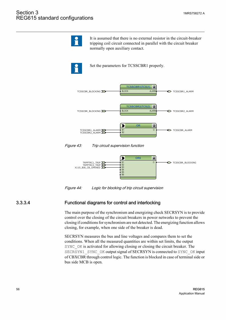
It is assumed that there is no external resistor in the circuit-breakertripping coil circuit connected in parallel with the circuit breakernormally open auxiliary contact.
Set the parameters for TCSSCBR1 properly.
TCSSCBR1(TCS(1)BLOCK ALARM
TCSSCBR2(TCS(2)BLOCK ALARM
ORB1B2
O
TCSSCBR_BLOCKING
TCSSCBR_BLOCKING
TCSSCBR1_ALARM
TCSSCBR1_ALARM
TCSSCBR2_ALARM
TCSSCBR2_ALARMTCSSCBR_ALARM
GUID-C01BBF87-22FF-437E-9A40-23CCEA199C51 V2 EN
Figure 43: Trip circuit supervision function
OR6B1B2B3B4B5B6
OTRPPTRC2_TRIPTRPPTRC1_TRIP
X110_BI8_CB_OPENED
TCSSCBR_BLOCKING
GUID-77EE438D-ABB9-41D2-84F4-930507384B0F V2 EN
Figure 44: Logic for blocking of trip circuit supervision
3.3.3.4 Functional diagrams for control and interlocking
The main purpose of the synchronism and energizing check SECRSYN is to providecontrol over the closing of the circuit breakers in power networks to prevent theclosing if conditions for synchronism are not detected. The energizing function allowsclosing, for example, when one side of the breaker is dead.
SECRSYN measures the bus and line voltages and compares them to set theconditions. When all the measured quantities are within set limits, the outputSYNC_OK is activated for allowing closing or closing the circuit breaker. TheSECRSYN1_SYNC_OK output signal of SECRSYN is connected to SYNC_OK inputof CBXCBR through control logic. The function is blocked in case of terminal side orbus side MCB is open.
Section 3 1MRS758272 AREG615 standard configurations
56 REG615Application Manual

SECRSYN1(SYNC(1BLOCKCL_COMMANDBYPASS
SYNC_INPROSYNC_OK
CL_FAIL_ALCMD_FAIL_AL
LLDBLLLBDLLBDLDB
OR6B1B2B3B4B5B6
O
SECRSYN1_SYNC_OK
X110_BI1_TERMINAL_VT_MCB_OPENX110_BI2_BUSBARL_VT_MCB_OPEN
BLOCK_SECRSYN1
BLOCK_SECRSYN1
GUID-9704EA86-855D-42AC-8907-3CC6A0E118FC V2 EN
Figure 45: Synchrocheck function
Two types of disconnector and earthing switch function blocks are available.DCSXSWI1...3 and ESSXSWI1...2 are status only type and DCXSWI1...2 andESXSWI1 are controllable type. By default, the status only blocks are connected in astandard configuration. The disconnector (CB truck) and line side earthing switchstatus information is connected to DCSXSWI1 and ESSXSI1 respectively.
DCSXSWI1(I<->OPOSOPENPOSCLOSE
OPENPOSCLOSEPOS
OKPOS DCSXSWI1_OKPOS
X110_BI4_CB_TRUCK_IN_TESTX110_BI3_CB_TRUCK_IN_SERVICE
GUID-08EEEC94-1EAC-45CB-897F-C7E45AF80C32 V2 EN
Figure 46: Disconnector control logic
ESSXSWI1(I<->OPOSOPENPOSCLOSE
OPENPOSCLOSEPOS
OKPOS
ESSXSWI1_OPENPOSX110_BI6_ES1_OPENEDX110_BI5_ES1_CLOSED
GUID-B1B96FFE-6504-4373-9143-0C9FD8B804B8 V2 EN
Figure 47: Earth switch control logic
The circuit breaker closing is enabled when the ENA_CLOSE input is activated. Theinput can be activated by the configuration logic, which is a combination of thedisconnector or breaker truck and the earth-switch position status and status of the triplogics.
The OKPOS output from DCSXSWI defines whether the disconnector or breakertruck is either open (in test position) or close (in service position). This output,together with the open earth switch and non-active trip signals, activates the close-enable signal to the circuit breaker control function block. The open operation forcircuit breaker is always enabled.
The SYNC_ITL_BYP input can be used, for example, to always enable the closing ofthe circuit breaker when the circuit breaker truck is in the test position.
1MRS758272 A Section 3REG615 standard configurations
REG615 57Application Manual

SYNC_ITL_BYP overrides, for example, active interlocking conditions when thecircuit breaker truck is closed in service position.
Connect the additional signals required for the application for closingand opening of circuit breaker.
CBXCBR1(I<->O CPOSOPENPOSCLOSEENA_OPENENA_CLOSEBLK_OPENBLK_CLOSEAU_OPENAU_CLOSETRIPSYNC_OKSYNC_ITL_BYP
SELECTEDEXE_OPEXE_CL
OP_REQCL_REQ
OPENPOSCLOSEPOS
OKPOSOPEN_ENAD
CLOSE_ENAD
TRUECBXCBR1_ENA_CLOSE
CBXCBR1_EXE_CLCBXCBR1_EXE_OP
CBXCBR1_BLK_CLOSEFALSE
X110_BI8_CB_OPENEDX110_BI7_CB_CLOSED
CBXCBR1_AU_OPENCBXCBR1_AU_CLOSE
SECRSYN1_SYNC_OK
GUID-BB1ED650-9B7D-48FB-A353-9AA6702904E2 V2 EN
Figure 48: Circuit breaker 1 control logic
ORB1B2
O CB_CLOSE_COMMANDCBXCBR1_EXE_CL
GUID-F56A6CCD-63A7-46DE-A278-577732873C08 V2 EN
Figure 49: Signal for closing coil of circuit breaker 1
OR6B1B2B3B4B5B6
O CB_OPEN_COMMANDTRPPTRC1_TRIPCBXCBR1_EXE_OP
GUID-AC90C2DE-F775-4710-B79C-0073FFD6E25A V2 EN
Figure 50: Signal for opening coil of circuit breaker 1
AND6B1B2B3B4B5B6
O
NOTIN OUT
NOTIN OUTTRPPTRC2_TRIP
CBXCBR1_ENA_CLOSE
TRPPTRC1_TRIP
DCSXSWI1_OKPOSESSXSWI1_OPENPOS
GUID-12D10670-281F-4E83-9AF0-D0F00CE8A38F V2 EN
Figure 51: Circuit breaker 1 close enable logic
Connect the higher-priority conditions before enabling the closing ofcircuit breaker. These conditions cannot be bypassed using bypassfeature of the function.
Section 3 1MRS758272 AREG615 standard configurations
58 REG615Application Manual

OR6B1B2B3B4B5B6
O CBXCBR1_BLK_CLOSET1PTTR1_BLK_CLOSE
GUID-A05280B3-2B7C-4931-9FE2-0695789A3340 V2 EN
Figure 52: Circuit breaker 1 close blocking logic
The configuration includes logic for generating circuit breaker external closing andopening command with the relay in local or remote mode.
Check the logic for the external circuit breaker closing command andmodify it according to the application.
Connect additional signals for opening and closing of circuit breakerin local or remote mode, if applicable for the configuration.
ANDB1B2
O
ANDB1B2
O
ORB1B2
O
FALSE
FALSE
CONTROL_LOCAL
CONTROL_REMOTE
CBXCBR1_AU_CLOSE
GUID-6B6BCEDB-7309-4BED-BEE2-66CCC4FDDB61 V2 EN
Figure 53: External closing command for circuit breaker 1
ANDB1B2
O
ANDB1B2
O
ORB1B2
O
FALSE
FALSE
CONTROL_LOCAL
CONTROL_REMOTE
CBXCBR1_AU_OPEN
GUID-8AB476A5-0AA2-4533-B119-A69EDFA5FFB3 V2 EN
Figure 54: External opening command for circuit breaker 1
3.3.3.5 Functional diagram for measurement functions
The phase current inputs to the relay are measured by the three-phase currentmeasurement function CMMXU1. The current input is connected to the X120 card inthe back panel. The sequence current measurement CSMSQI1 measures the sequencecurrent and the residual current measurement RESCMMXU1 measures the residualcurrent.
1MRS758272 A Section 3REG615 standard configurations
REG615 59Application Manual

The three-phase line side phase voltage inputs to the relay are measured by the three-phase voltage measurement function VMMXU1 whereas the bus side voltage input tothe relay is measured by the three-phase voltage measurement function VMMXU2.The three-phase voltage input is connected to the X130 card in the back panel. Thesequence voltage measurement VSMSQI1 measures the sequence voltage and theresidual voltage measurement RESVMMXU1 measures the residual voltage on theline side.
The measurements can be seen in the LHMI and they are available under themeasurement option in the menu selection. Based on the settings, function blocks cangenerate low alarm or warning and high alarm or warning signals for the measuredcurrent values.
The frequency measurement FMMXU1 of the power system and three-phase powerand energy measurement PEMMXU1 are available. Load profile record LDPRLRC1is included in the measurements sheet. LDPRLRC1 offers the ability to observe theloading history of the corresponding feeder.
CMMXU1(3I(1))BLOCK HIGH_ALARM
HIGH_WARNLOW_WARN
LOW_ALARM
GUID-96C8ED35-DFCE-46BC-A80B-A08033C11B63 V2 EN
Figure 55: Current measurement: Three-phase current measurement
CSMSQI1(I1,I2,I
GUID-D7B8A6D1-5D30-432A-BA7E-EFD3EEFCFF83 V2 EN
Figure 56: Current measurement: Sequence current measurement
RESCMMXU1(Io(1)BLOCK HIGH_ALARM
HIGH_WARN
GUID-E920C019-B93B-42E2-8AF5-3095829351AE V2 EN
Figure 57: Current measurement: Residual current measurement
VMMXU1BLOCK HIGH_ALARM
HIGH_WARNLOW_WARN
LOW_ALARM
GUID-C56D56FD-91C3-4C7F-95D2-E11ADC494AF1 V2 EN
Figure 58: Voltage measurement: Three-phase voltage measurement(Terminal side)
Section 3 1MRS758272 AREG615 standard configurations
60 REG615Application Manual

VMMXU2BLOCK HIGH_ALARM
HIGH_WARNLOW_WARN
LOW_ALARM
GUID-864991D4-B7CF-4444-94CA-B1C513ECD70B V2 EN
Figure 59: Voltage measurement: Three-phase voltage measurement (Busside)
VSMSQI1
GUID-CD9595C7-7643-4733-9D97-D9CC6AC26F70 V2 EN
Figure 60: Voltage measurement: Sequence voltage measurement
RESVMMXU1BLOCK HIGH_ALARM
HIGH_WARN
GUID-8505E78F-C298-4EA1-B0E2-288A9BE3356E V2 EN
Figure 61: Voltage measurement: Residual voltage measurement
FMMXU1
GUID-BF3E65A6-5F2D-43A2-8E9A-F8F068A38154 V2 EN
Figure 62: Other measurement: Frequency measurement
PEMMXU1RSTACM
GUID-1200033A-FF93-4313-822D-38D4015F567E V2 EN
Figure 63: Other measurement: Three phase power and energy measurement
FLTRFRC1BLOCKCB_CLRD
GUID-21FA63CF-E5FC-4B43-8071-93B5934473B1 V2 EN
Figure 64: Other measurement: Data monitoring
LDPRLRC1RSTMEM MEM_WARN
MEM_ALARM
GUID-097212FA-0AAC-4F1C-B5C1-247AC28E90CE V2 EN
Figure 65: Other measurement: Load profile record
1MRS758272 A Section 3REG615 standard configurations
REG615 61Application Manual

3.3.3.6 Functional diagrams for IOs and alarm LEDs
ORB1B2
O
ORB1B2
O
ORB1B2
O
ORB1B2
O
ORB1B2
O
ORB1B2
O
ORB1B2
O
ORB1B2
O X110_BI8_CB_OPENED
X110_BI7_CB_CLOSED
X110_BI4_CB_TRUCK_IN_TEST
X110_BI3_CB_TRUCK_IN_SERVICE
X110_BI6_ES1_OPENED
X110_BI5_ES1_CLOSED
X110_BI1_TERMINAL_VT_MCB_OPEN
X110_BI2_BUSBARL_VT_MCB_OPEN
X110 (BIO-H)_110.X110-Input 5
X110 (BIO)_110.X110-Input 3
X110 (BIO)_110.X110-Input 4
X110 (BIO)_110.X110-Input 1
X110 (BIO)_110.X110-Input 5
X110 (BIO-H)_110.X110-Input 4
X110 (BIO-H)_110.X110-Input 2
X110 (BIO)_110.X110-Input 2
X110 (BIO-H)_110.X110-Input 6
X110 (BIO-H)_110.X110-Input 7
X110 (BIO)_110.X110-Input 7
X110 (BIO)_110.X110-Input 6
X110 (BIO-H)_110.X110-Input 3
X110 (BIO-H)_110.X110-Input 8
X110 (BIO)_110.X110-Input 8
X110 (BIO-H)_110.X110-Input 1
GUID-8F305E99-BB3B-49F0-8CDE-89903FCED13E V2 EN
Figure 66: Default binary input - X110
X120_BI3_RST_LOCKOUT
X120_BI2_CB_SPRING_CHARGED
X120_BI1_GAS_PRESSURE_ALARM
X120 (AIM)_120.X120-Input 1
X120 (AIM)_120.X120-Input 2
X120 (AIM)_120.X120-Input 3GUID-59200644-FD21-4516-9F94-A5C659319171 V2 EN
Figure 67: Default binary input - X120
Section 3 1MRS758272 AREG615 standard configurations
62 REG615Application Manual

CB_OPEN_COMMAND
GENERAL_OPERATE_PULSE
TRPPTRC2_TRIP
GENERAL_START_PULSE
CB_CLOSE_COMMAND
CCBRBRF1_TRBU
X100 (PSM)_100.X100-PO1
X100 (PSM)_100.X100-PO3
X100 (PSM)_100.X100-PO4
X100 (PSM)_100.X100-SO1
X100 (PSM)_100.X100-SO2
X100 (PSM)_100.X100-PO2
GUID-65462B7A-EB91-455B-BACF-D86D23F292B3 V2 EN
Figure 68: Default binary output - X100
TRPPTRC3_TRIP
TRPPTRC4_TRIP
TRPPTRC5_TRIP
VOLTAGE_AND_FREQ_OPERATE_PULSE
OC_OPERATE_PULSE
EF_OPERATE_PULSE
INTERCONNECTED_OPERATE_PULSE
X110 (BIO-H)_110.X110-HSO1
X110 (BIO-H)_110.X110-HSO2
X110 (BIO-H)_110.X110-HSO3
X110 (BIO)_110.X110-SO1
X110 (BIO)_110.X110-SO2
X110 (BIO)_110.X110-SO3
X110 (BIO)_110.X110-SO4GUID-1BB2E60B-2CF2-4E9D-BF5D-A5D61DD55A56 V2 EN
Figure 69: Default binary output - X110
1MRS758272 A Section 3REG615 standard configurations
REG615 63Application Manual

LED1OKALARMRESET
LED2OKALARMRESET
LED3OKALARMRESET
LED4OKALARMRESET
LED5OKALARMRESET
OR6B1B2B3B4B5B6
O
ORB1B2
O
ANDB1B2
O
ORB1B2
O
X110_BI8_CB_OPENEDSECRSYN1_SYNC_OK
PHIPTOC1_OPERATE
VVSPPAM1_OPERATEDQPTUV1_OPERATE
EFHPTOC1_OPERATE
DPHxPDOC_OPERATE
LVRTPTUV_OPERATE
ROVPTOV_OPERATE
DOPPDPR_OPERATE
GUID-2C6025B4-A935-427E-AC8A-FDA640226E05 V2 EN
Section 3 1MRS758272 AREG615 standard configurations
64 REG615Application Manual

LED6OKALARMRESET
LED7OKALARMRESET
LED8OKALARMRESET
LED9OKALARMRESET
LED10OKALARMRESET
LED11OKALARMRESET
OR6B1B2B3B4B5B6
O
OR6B1B2B3B4B5B6
O
ORB1B2
O
CCBRBRF1_TRBU
T1PTTR1_OPERATE
SEQSPVC1_FUSEF_U
PSPTUV_OPERATENSPTOV_OPERATEPHPTOV_OPERATEPHPTUV_OPERATE
FREQUENCY_OPERATE
TCSSCBR_ALARMSSCBR1_ALARMS
NSPTOC_OPERATE
DISTURB_RECORD_TRIGGERED
ARC_OPERATE
CCSPVC1_ALARM
GUID-F899289E-7F2D-4670-B650-5BDAC9FE20DA V2 EN
Figure 70: Default LED connection
3.3.3.7 Functional diagram for other timer logics
The configuration includes the overcurrent operate, earth-fault operate, voltage/frequency operate and interconnected protection operate logic. The operate logics areconnected to minimum pulse timer TPGAPC for setting the minimum pulse length forthe outputs. The output from TPGAPC is connected to binary outputs.
1MRS758272 A Section 3REG615 standard configurations
REG615 65Application Manual

TPGAPC2(TP(2))IN1IN2
OUT1OUT2
ORB1B2
O
ORB1B2
O
OC_OPERATE_PULSEEF_OPERATE_PULSEPHIPTOC1_OPERATE
EFHPTOC1_OPERATE
DPHxPDOC_OPERATE
ROVPTOV_OPERATE
GUID-01CBAF9B-F169-42F7-AD7A-6C5FF66238C9 V2 EN
Figure 71: Timer logic for overcurrent and earth-fault operate pulse
TPGAPC3(TP(3))IN1IN2
OUT1OUT2
OR6B1B2B3B4B5B6
O
OR6B1B2B3B4B5B6
O
VOLTAGE_AND_FREQ_OPERATE_PULSEINTERCONNECTED_OPERATE_PULSE
VVSPPAM1_OPERATEDQPTUV1_OPERATE
PSPTUV_OPERATENSPTOV_OPERATEPHPTOV_OPERATEPHPTUV_OPERATE
FREQUENCY_OPERATE
LVRTPTUV_OPERATE
GUID-EC03925C-7289-42CE-8C75-D1842383BE1F V2 EN
Figure 72: Timer logic for voltage/frequency and interconnected protectionoperate pulse
3.3.3.8 Other functions
The configuration includes three instances of directional earth-fault protection,transient/intermittent earth-fault protection, 18 instances of multipurpose protectionMAPGAPC, power quality function, two more instances of frequency protection anddifferent types of timers and control functions. These functions are not included inapplication configuration but they can be added based on the system requirements.
3.4 Standard configuration C
3.4.1 Applications
The standard configuration with power protection, 100% stator earth-fault protectionwith third harmonic-based stator earth-fault protection, overcurrent and directionalearth-fault protection, voltage and frequency based protection, underexcitation,underimpedance and out-of-step protection is mainly intended for the main protectionof a small size synchronous power generator or as backup protection for a medium sizesynchronous power generator.
The IED with a standard configuration is delivered from the factory with defaultsettings and parameters. The end user flexibility for incoming, outgoing and internalsignal designation within the IED enables this configuration to be further adapted to
Section 3 1MRS758272 AREG615 standard configurations
66 REG615Application Manual

different primary circuit layouts and the related functionality needs by modifying theinternal functionality using PCM600.
3.4.2 Functions
Uo
Io>→67N-1
Io>>→67N-2
2×
Uo>59G
2×Io>>
51N-2G
TCSTCM
OPTSOPTM
2×
FUSEF60
CBCMCBCM
GENERATOR PROTECTION RELAY STANDARD CONFIGURATION
PROTECTION LOCAL HMI
RL
ClearESCI
O
Configuration ASystemHMITimeAuthorization
RL
ClearESCI
O
U12 0. 0 kVP 0.00 kWQ 0.00 kVAr
IL2 0 A
A
Io
REG615 C
ALSO AVAILABLE
- Disturbance and fault recorders- Event log and recorded data- High-Speed Output module (optional)- Local/Remote push button on LHMI- Self-supervision - Time synchronization: IEEE 1588 v2,
SNTP, IRIG-B- User management- Web HMI
CONDITION MONITORING AND SUPERVISION
COMMUNICATION
Protocols: IEC 61850-8-1/-9-2LE Modbus®
IEC 60870-5-103 DNP3Interfaces: Ethernet: TX (RJ45), FX (LC) Serial: Serial glass fiber (ST), RS-485, RS-232Redundant protocols: HSR PRP RSTP
3I
UL1, L2, L3
Io
Master TripLockout relay
94/86
Uo
MEASUREMENT
- I, U, Io, Uo, P, Q, E, pf, f- Limit value supervision- Load profile record- RTD/mA measurement (optional)- Symmetrical components- Frequency adaptivity
4
5
Analog interface types 1)
Current transformer
Voltage transformer1) Conventional transformer inputs
PQM3UPQM3V
PQMUPQMV
PQM3IPQM3I
2×RTD1×mA
MAPMAP
18×
ORAND
dUo>/Uo3H27/59THD
Master TripLockout relay
94/86
U2>47O-
U1<47U+
3U<27
2× 2×2×
3U>59
f>/f<,df/dt81
2× 6×
U/f>24
3I
ARC50L/50NL
3I>>>50P/51P
3I2f>68
3I>/Io>BF51BF/51NBF
P>/Q>32R/32O
3×
3I>51P-1
3I>>51P-2
I2>M46M
X<40
P<32U
2×3×
3Ith>T/G/C49T/G/C
3I(U)>51V
Z<G21G
3×
∆IoIo
UL1, L2, L3
EXC.AVR
CONTROL AND INDICATION 1)
Object Ctrl 2) Ind 3)
CB
DC
ES1) Check availability of binary inputs/outputs from technical documentationControl and indication function for primary objectStatus indication function forprimary object
2)
3)
1 -
2 3
1 2
REMARKS
Optionalfunction
No. ofinstances
Alternative function to be defined when ordering
OR
Io/Uo
Calculatedvalue
3×
Master TripLockout relay
94/86
3×2×
PQUUBPQVUB
2×
OOS78
GUID-1536B574-54F9-4C47-BD65-175410DFEE46 V2 EN
Figure 73: Functionality overview for standard configuration C
1MRS758272 A Section 3REG615 standard configurations
REG615 67Application Manual

3.4.2.1 Default I/O connections
Connector pins for each input and output are presented in the IED physicalconnections section.
Table 16: Default connections for binary inputs
Binary input DescriptionX110-BI1 Terminal VT secondary MCB open
X110-BI2 Neutral VT secondary MCB open
X110-BI3 Circuit breaker truck in (service position) indication
X110-BI4 Circuit breaker truck out (test position) indication
X110-BI5 Earthing switch closed indication
X110-BI6 Earthing switch open indication
X110-BI7 Circuit breaker closed indication
X110-BI8 Circuit breaker open indication
X120-BI1 Circuit breaker low gas pressure indication
X120-BI2 Circuit breaker spring charged indication
X120-BI3 -
X120-BI4 -
X130-BI1 External trip 1
X130-BI2 External trip 2
X130-BI3 Lockout reset
X130-BI4 Field excitation open indication
Table 17: Default connections for binary outputs
Binary output DescriptionX100-PO1 Generator circuit breaker open command/trip 2
X100-PO2 Breaker failure backup trip to upstream breaker
X100-SO1 Prime mover shutdown
X100-SO2 General protection operate indication
X100-PO3 Generator circuit breaker open command/trip 1
X100-PO4 Field excitation circuit breaker open command
X110-SO1 Overcurrent protection operated
X110-SO2 Earth fault protection operated
X110-SO3 Voltage or frequency protection operated
X110-SO4 Thermal overload of NPS protection operated
X110-HSO1 Arc protection instance 1 operate activated
X110-HSO2 Arc protection instance 2 operate activated
X110-HSO3 Arc protection instance 3 operate activated
Section 3 1MRS758272 AREG615 standard configurations
68 REG615Application Manual
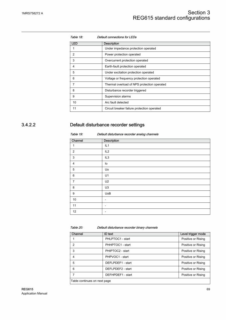
Table 18: Default connections for LEDs
LED Description1 Under impedance protection operated
2 Power protection operated
3 Overcurrent protection operated
4 Earth-fault protection operated
5 Under excitation protection operated
6 Voltage or frequency protection operated
7 Thermal overload of NPS protection operated
8 Disturbance recorder triggered
9 Supervision alarms
10 Arc fault detected
11 Circuit breaker failure protection operated
3.4.2.2 Default disturbance recorder settings
Table 19: Default disturbance recorder analog channels
Channel Description1 IL1
2 IL2
3 IL3
4 Io
5 Uo
6 U1
7 U2
8 U3
9 UoB
10 -
11 -
12 -
Table 20: Default disturbance recorder binary channels
Channel ID text Level trigger mode1 PHLPTOC1 - start Positive or Rising
2 PHHPTOC1 - start Positive or Rising
3 PHIPTOC2 - start Positive or Rising
4 PHPVOC1 - start Positive or Rising
5 DEFLPDEF1 - start Positive or Rising
6 DEFLPDEF2 - start Positive or Rising
7 DEFHPDEF1 - start Positive or Rising
Table continues on next page
1MRS758272 A Section 3REG615 standard configurations
REG615 69Application Manual

Channel ID text Level trigger mode8 EFHPTOC1 - start Positive or Rising
9 MNSPTOC1 - start Positive or Rising
10 MNSPTOC2 - start Positive or Rising
11 PHPTUV1 - start Positive or Rising
12 PHPTUV2 - start Positive or Rising
13 H3EFPSEF1 - start Positive or Rising
14 PHPTOV1 - start Positive or Rising
15 PHPTOV2 - start Positive or Rising
16 FRPFRQ1 - start Positive or Rising
17 FRPFRQ2 - start Positive or Rising
18 FRPFRQ3 - start Positive or Rising
19 FRPFRQ4 - start Positive or Rising
20 OEPVPH1 - start Positive or Rising
21 UZPDIS1 - start Positive or Rising
22 UEXPDIS1 - start Positive or Rising
23 ROVPTOV1 - start Positive or Rising
24 ROVPTOV2 - start Positive or Rising
25 NSPTOV1 - start Positive or Rising
26 NSPTOV2 - start Positive or Rising
27 PSPTUV1 - start Positive or Rising
28 PSPTUV2 - start Positive or Rising
29 DUPPDPR1 - start Positive or Rising
30 DUPPDPR2 - start Positive or Rising
31 DOPPDPR1 - start Positive or Rising
32 DOPPDPR2 - start Positive or Rising
33 DOPPDPR3 - start Positive or Rising
34 T2PTTR1 - start Positive or Rising
35 CCBRBRF1 - trret Level trigger off
36 CCBRBRF1 - trbu Level trigger off
37 PHLPTOC1 - operate Level trigger off
PHHPTOC1 - operate
PHIPTOC2 - operate
PHPVOC1 - operate
38 EFHPTOC1 - operate Level trigger off
DEFLPDEF1 - operate
DEFLPDEF2 - operate
DEFHPDEF1 - operate
39 MNSPTOC1 - operate Level trigger off
MNSPTOC2 - operate
Table continues on next page
Section 3 1MRS758272 AREG615 standard configurations
70 REG615Application Manual

Channel ID text Level trigger mode40 PHPTUV1 - operate Level trigger off
PHPTUV2 - operate
41 H3EFPSEF1 - operate Level trigger off
42 PHPTOV1 - operate Level trigger off
PHPTOV2 - operate
43 FRPFRQ1 - operate Level trigger off
FRPFRQ2 - operate
FRPFRQ3 - operate
FRPFRQ4 - operate
44 OEPVPH1 - operate Level trigger off
45 UZPDIS1 - operate Level trigger off
46 UEXPDIS1 - operate Level trigger off
47 ROVPTOV1 - operate Level trigger off
ROVPTOV2 - operate
NSPTOV1 - operate
NSPTOV2 - operate
PSPTUV1 - operate
PSPTUV2 - operate
48 INRPHAR1 - blk2h Level trigger off
49 DUPPDPR1 - operate Level trigger off
DUPPDPR2 - operate
DOPPDPR1 - operate
DOPPDPR2 - operate
DOPPDPR2 - operate
50 T2PTTR1 - operate Level trigger off
51 SEQSPVC1- fusef 3ph Level trigger off
52 SEQSPVC1- fusef u Level trigger off
53 X130BI2 - Ext trip1 Positive or Rising
54 X130BI2 - Ext trip2 Positive or Rising
55 X110BI4 - Field Excitation open Positive or Rising
56 X110BI7 - CB closed Level trigger off
57 X110BI8 - CB open Level trigger off
58 ARCSARC1 - ARC flt det Level trigger off
ARCSARC2 - ARC flt det
ARCSARC3 - ARC flt det
59 ARCSARC1 - operate Positive or Rising
60 ARCSARC2 - operate Positive or Rising
61 ARCSARC3 - operate Positive or Rising
1MRS758272 A Section 3REG615 standard configurations
REG615 71Application Manual

3.4.3 Functional diagrams
The functional diagrams describe the default input, output, alarm LED and function-to-function connections. The default connections can be viewed and changed withPCM600 according to the application requirements.
The analog channels have fixed connections to the different function blocks inside theIED’s standard configuration. However, the 12 analog channels available for thedisturbance recorder function are freely selectable as a part of the disturbancerecorder’s parameter settings.
The phase currents to the IED are fed from a current transformer. It is assumed that thecore balance CT is provided both on line and neutral side of the generator and areconnected such that the differential residual current is fed to the IED.
The terminal side phase voltages to the IED are fed from a voltage transformer. Theresidual voltage to the IED is fed from either residually connected VTs, an open deltaconnected VT or internally calculated.
The IED offers six different settings groups which can be set based on individualneeds. Each group can be activated or deactivated using the setting group settingsavailable in the IED.
Depending on the communication protocol the required function block needs to beinitiated in the configuration. The Application Configuration tool also includes fixedBoolean signals TRUE and FALSE which can be used according to the applicationneeds.
3.4.3.1 Functional diagrams for protection
The functional diagrams describe the protection functionality of the relay in detail andaccording to the factory set default connections.
Three non-directional overcurrent stages are offered for detecting phase faults ingenerators. In addition to overcurrent stages, one instance of voltage dependentovercurrent protection is also provided which can be used as a backup protectionagainst phase faults. During certain conditions, fault current for three phase faults maybe less than full load current of the generator. This may not get noticed by phaseovercurrent protection, but the fault will cause generator terminal voltage to drop.Voltage dependent overcurrent protection can be used to detect and operate suchfaults.
Section 3 1MRS758272 AREG615 standard configurations
72 REG615Application Manual

PHIPTOC1(3I>>>(BLOCKENA_MULT
OPERATESTART
PHLPTOC1(3I>(1)BLOCKENA_MULT
OPERATESTART
PHHPTOC1(3I>>(1BLOCKENA_MULT
OPERATESTART
OR6B1B2B3B4B5B6
O
PHLPTOC1_OPERATE
PHLPTOC1_OPERATE
PHHPTOC1_OPERATE
PHHPTOC1_OPERATE
PHIPTOC1_OPERATE
PHIPTOC1_OPERATE
PHLPTOC1_START
PHHPTOC1_START
PHIPTOC1_START
INRPHAR1_BLK2H
INRPHAR1_BLK2H
PHxPTOC_OPERATE
GUID-4368AB17-6EEE-49A6-B3A3-072AFB612451 V2 EN
Figure 74: Overcurrent protection function
PHPVOC1BLOCKENA_MULTENA_LOW_LIM
OPERATESTART
PHPVOC1_OPERATEPHPVOC1_START
SEQSPVC1_FUSEF_U
GUID-5B9BA191-7DC4-40A5-96F3-FAC1662560FE V2 EN
Figure 75: Voltage dependent overcurrent protection function
The output BLK2H of three-phase inrush detector INRPHAR1 either blocks thefunction or multiplies the active settings for any of the available overcurrent or earth-fault function blocks. In the configuration, INRPHAR1 blocks the high andinstantaneous stage of non-directional overcurrent protection.
INRPHAR1BLOCK BLK2H INRPHAR1_BLK2H
GUID-894F068C-661D-486D-B125-4A96CD9D614E V2 EN
Figure 76: Inrush detector function
Two negative-sequence overcurrent protection stages MNSPTOC1 and MNSPTOC2are provided for phase unbalance protection. These functions are used to protectagainst unbalance conditions due to unbalance load or unsymmetrical faults.
1MRS758272 A Section 3REG615 standard configurations
REG615 73Application Manual

MNSPTOC1BLOCK OPERATE
STARTBLK_RESTART
MNSPTOC2BLOCK OPERATE
STARTBLK_RESTART
ORB1B2
O
MNSPTOC1_OPERATE
MNSPTOC1_OPERATE
MNSPTOC2_OPERATE
MNSPTOC2_OPERATE
MNSPTOC1_START
MNSPTOC2_START
MNSPTOC_OPERATE
GUID-D4F3CED7-66B6-4925-8598-0CE20854D91E V2 EN
Figure 77: Negative sequence overcurrent protection function
One non-directional sensitive earth-fault stage EFHPTOC1 and three directionalearth-fault stages DEFxPDEF are offered for providing primary and backupprotection for generator earth-fault protection. Transient/intermittent earth-faultprotection INTRPTEF is used for transient based earth-fault protection.
DEFHPDEF1BLOCKENA_MULTRCA_CTL
OPERATESTART
DEFLPDEF1BLOCKENA_MULTRCA_CTL
OPERATESTART
DEFLPDEF2BLOCKENA_MULTRCA_CTL
OPERATESTART
DEFLPDEF2_OPERATE
DEFLPDEF1_OPERATE
DEFHPDEF1_OPERATE
DEFLPDEF2_START
DEFHPDEF1_START
DEFLPDEF1_START
GUID-B21DA613-47F3-45B8-89E9-70E8E0D076DA V2 EN
Figure 78: Directional earth-fault protection function
Section 3 1MRS758272 AREG615 standard configurations
74 REG615Application Manual

EFHPTOC1BLOCKENA_MULT
OPERATESTART
OR6B1B2B3B4B5B6
ODEFLPDEF2_OPERATEDEFLPDEF1_OPERATE
DEFHPDEF1_OPERATE
EFHPTOC1_OPERATE
EFHPTOC1_OPERATE
EFHPTOC1_START
EF_OPERATE
GUID-C7981340-D7D1-4F19-9A89-08343F9C8022 V2 EN
Figure 79: Earth-fault protection function
Third harmonic-based stator earth-fault protection is provided to give 100% statorwinding protection. The protection is blocked by MCB open from neutral side VT.
H3EFPSEF1BLOCKGCB_CLOSED
OPERATESTART
INT_BLKDX110_BI7_CB_CLOSED
H3EFPSEF1_OPERATEH3EFPSEF1_START
X110_BI2_NEUTRAL_VT_MCB_OPEN
GUID-C27337B1-C47F-4DF8-A1F7-817D5738427B V2 EN
Figure 80: Third harmonic-based stator earth-fault protection function
Three-phase thermal overload protection, two time constants, T2PTTR1 detectscontinuous overloading conditions preventing excessive insulation damage in thelong run.
T2PTTR1BLOCKAMB_TEMP
OPERATESTARTALARM
BLK_CLOSE
T2PTTR1_STARTT2PTTR1_OPERATE
GUID-C253628A-3CC5-4868-AAB6-8B563DC52AEB V2 EN
Figure 81: Thermal overcurrent protection function
Circuit breaker failure protection CCBRBRF1 is initiated via the START input by anumber of different protection functions available in the relay. The breaker failureprotection function offers different operating modes associated with the circuitbreaker position and the measured phase and residual currents.
The circuit breaker failure protection function has two operating outputs: TRRET andTRBU. The TRRET operating output is used for retripping its own breaker throughTRPPTRC2_TRIP. The TRBU output gives a backup trip to the breaker feedingupstream. For this purpose, the TRBU operating output signal is connected to thebinary output X100:PO2. In addition, TRBU operating output is also used to trip fieldexcitation circuit breaker through TRPPTRC6_TRIP_FIELD EXCITATION.
1MRS758272 A Section 3REG615 standard configurations
REG615 75Application Manual

CCBRBRF1BLOCKSTARTPOSCLOSECB_FAULT
CB_FAULT_ALTRBU
TRRET
OR6B1B2B3B4B5B6
O
OR6B1B2B3B4B5B6
O
OR6B1B2B3B4B5B6
O CCBRBRF1_TRBU
X110_BI7_CB_CLOSED
PHLPTOC1_OPERATEPHHPTOC1_OPERATEPHIPTOC1_OPERATEPHPVOC1_OPERATE
DEFLPDEF2_OPERATEDEFLPDEF1_OPERATE
DEFHPDEF1_OPERATEEFHPTOC1_OPERATEARCSARC1_OPERATEARCSARC2_OPERATEARCSARC3_OPERATE
CCBRBRF1_TRRET
GUID-B1503522-475D-4569-9612-0A2F1A155418 V2 EN
Figure 82: Circuit breaker failure protection function
Three arc protection ARCSARC1...3 stages are included as an optional function. Thearc protection offers individual function blocks for three arc sensors that can beconnected to the relay. Each arc protection function block has two different operationmodes, that is, with or without the phase and residual current check.
The operating signals from ARCSARC1...3 are connected to both generator circuitbreaker trip logic TRPPTRC1 and TRPPTRC2 and also to field excitation circuitbreaker trip logic TRPPTRC6. If the relay has been ordered with high speed binaryoutputs, the individual operating signals from ARCSARC1...3 are connected todedicated trip logic TRPPTRC3...5. The output of TRPPTRC3...5 is available at highspeed outputs X110:HSO1, X110:HSO2 and X110:HSO3.
OR6B1B2B3B4B5B6
O
ARCSARC1BLOCKREM_FLT_ARCOPR_MODE
OPERATEARC_FLT_DET
ARCSARC2BLOCKREM_FLT_ARCOPR_MODE
OPERATEARC_FLT_DET
ARCSARC3BLOCKREM_FLT_ARCOPR_MODE
OPERATEARC_FLT_DET
ARCSARC1_OPERATE
ARCSARC1_OPERATE
ARCSARC2_OPERATE
ARCSARC2_OPERATE
ARCSARC3_OPERATE
ARCSARC3_OPERATE
ARCSARC1_ARC_FLT_DET
ARCSARC2_ARC_FLT_DET
ARCSARC3_ARC_FLT_DET
ARC_OPERATE
GUID-366A56E9-D593-43F8-AFC5-78481CEA8E79 V2 EN
Figure 83: Arc protection function
Section 3 1MRS758272 AREG615 standard configurations
76 REG615Application Manual
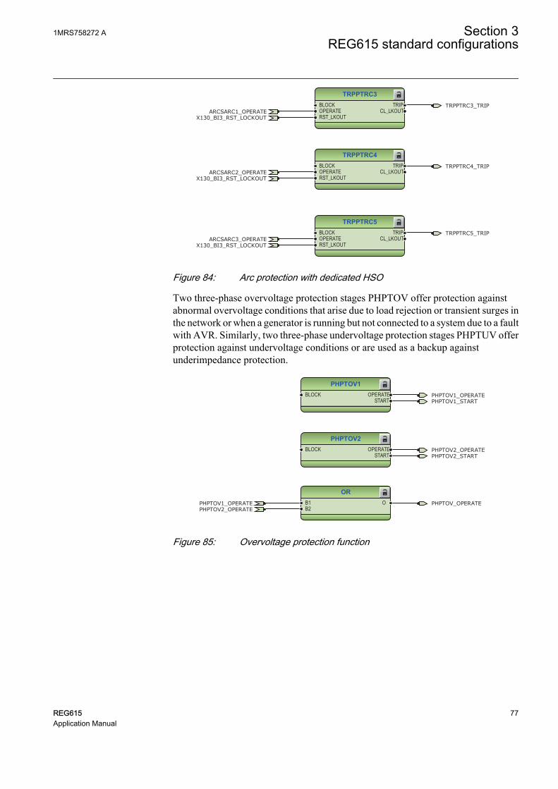
TRPPTRC3BLOCKOPERATERST_LKOUT
TRIPCL_LKOUT
TRPPTRC4BLOCKOPERATERST_LKOUT
TRIPCL_LKOUT
TRPPTRC5BLOCKOPERATERST_LKOUT
TRIPCL_LKOUT
TRPPTRC3_TRIP
TRPPTRC4_TRIP
TRPPTRC5_TRIP
X130_BI3_RST_LOCKOUT
X130_BI3_RST_LOCKOUT
X130_BI3_RST_LOCKOUT
ARCSARC1_OPERATE
ARCSARC2_OPERATE
ARCSARC3_OPERATE
GUID-A21CD488-6B6A-47C7-AD6F-94C046BD1B2B V2 EN
Figure 84: Arc protection with dedicated HSO
Two three-phase overvoltage protection stages PHPTOV offer protection againstabnormal overvoltage conditions that arise due to load rejection or transient surges inthe network or when a generator is running but not connected to a system due to a faultwith AVR. Similarly, two three-phase undervoltage protection stages PHPTUV offerprotection against undervoltage conditions or are used as a backup againstunderimpedance protection.
PHPTOV1BLOCK OPERATE
START
PHPTOV2BLOCK OPERATE
START
ORB1B2
O
PHPTOV1_OPERATE
PHPTOV1_OPERATE
PHPTOV2_OPERATE
PHPTOV2_OPERATE
PHPTOV1_START
PHPTOV2_START
PHPTOV_OPERATE
GUID-2904E2B7-20B7-41E7-9A06-7FF2BD8A3BC5 V2 EN
Figure 85: Overvoltage protection function
1MRS758272 A Section 3REG615 standard configurations
REG615 77Application Manual

PHPTUV1BLOCK OPERATE
START
PHPTUV2BLOCK OPERATE
START
ORB1B2
O
PHPTUV2_OPERATE
PHPTUV2_OPERATE
PHPTUV1_OPERATE
PHPTUV1_OPERATE
PHPTUV1_START
PHPTUV2_START
BLOCK_UV
BLOCK_UV
PHPTUV_OPERATE
GUID-2D4EE8AA-C017-43A7-BE49-6569FF7BC09A V2 EN
Figure 86: Undervoltage protection function
Two stages of each positive-sequence undervoltage PSPTUV and negative-sequenceovervoltage NSPTOV protection functions are also provided. A failure in the voltagemeasuring circuit is detected by the fuse failure function. The fuse failure activationis connected to block undervoltage protection functions and voltage based unbalanceprotection functions to avoid faulty tripping. In addition, undervoltage protection isalso blocked when a generator circuit breaker is in open position.
NSPTOV1BLOCK OPERATE
START
NSPTOV2BLOCK OPERATE
START
ORB1B2
O
NSPTOV2_OPERATE
NSPTOV2_OPERATE
NSPTOV1_OPERATE
NSPTOV1_OPERATE
NSPTOV1_START
NSPTOV2_START
SEQSPVC1_FUSEF_U
SEQSPVC1_FUSEF_U
NSPTOV_OPERATE
GUID-6B465C7E-C870-4C22-97DF-01F7189CF8B5 V2 EN
Figure 87: Negative sequence overvoltage protection function
Section 3 1MRS758272 AREG615 standard configurations
78 REG615Application Manual

PSPTUV1BLOCK OPERATE
START
PSPTUV2BLOCK OPERATE
START
ORB1B2
O
PSPTUV2_OPERATE
PSPTUV2_OPERATE
PSPTUV1_OPERATE
PSPTUV1_OPERATE
PSPTUV1_START
PSPTUV2_START
BLOCK_UV
BLOCK_UV
PSPTUV_OPERATE
GUID-BA97F786-296F-4A90-B583-113018D9592E V2 EN
Figure 88: Positive sequence undervoltage protection function
Residual overvoltage protection ROVPTOV provides protection against stator earthfaults from 5% to 100% of winding from neutral. Two instances of ROVPTOV areprovided.
ROVPTOV1BLOCK OPERATE
START
ROVPTOV2BLOCK OPERATE
START
ORB1B2
O
ROVPTOV1_OPERATE
ROVPTOV1_OPERATE
ROVPTOV2_OPERATE
ROVPTOV2_OPERATE
ROVPTOV1_START
ROVPTOV2_START
ROVPTOV_OPERATE
GUID-FD66FB6E-AE3B-485A-B94D-5051B110C860 V2 EN
Figure 89: Residual overvoltage protection function
The selectable underfrequency or overfrequency or rate of change of frequencyprotection FRPFRQ prevents damage to network components under unwantedfrequency conditions. The function also contains a selectable rate of change of thefrequency (gradient) protection to detect an increase or decrease in the fast powersystem frequency at an early stage. This can be used as an early indication of adisturbance in the system. Configuration offers six instances of frequency protection,these instances can be configured to operate as underfrequency or overfrequency orrate of change of frequency according to the system requirement. The frequencyprotection is blocked when generator CB is in open position.
1MRS758272 A Section 3REG615 standard configurations
REG615 79Application Manual

FRPFRQ1BLOCK OPERATE
OPR_OFRQOPR_UFRQ
OPR_FRGSTART
ST_OFRQST_UFRQ
ST_FRG
FRPFRQ2BLOCK OPERATE
OPR_OFRQOPR_UFRQ
OPR_FRGSTART
ST_OFRQST_UFRQ
ST_FRG
FRPFRQ3BLOCK OPERATE
OPR_OFRQOPR_UFRQ
OPR_FRGSTART
ST_OFRQST_UFRQ
ST_FRG
FRPFRQ4BLOCK OPERATE
OPR_OFRQOPR_UFRQ
OPR_FRGSTART
ST_OFRQST_UFRQ
ST_FRG
OR6B1B2B3B4B5B6
O
FRPFRQ2_OPERATE
FRPFRQ2_OPERATE
FRPFRQ4_OPERATE
FRPFRQ4_OPERATE
FRPFRQ3_OPERATE
FRPFRQ3_OPERATE
FRPFRQ1_OPERATE
FRPFRQ1_OPERATE
FRPFRQ1_START
FRPFRQ2_START
FRPFRQ3_START
FRPFRQ4_START
BLOCK_FREQ
BLOCK_FREQ
BLOCK_FREQ
BLOCK_FREQ
FREQUENCY_OPERATE
GUID-0E0FBEC6-9ABE-40FB-AFAD-E781D244A22E V2 EN
Figure 90: Frequency protection function
Three instances of reverse power/directional overpower protection DOPPDPR areprovided to detect either loss of prime mover or detecting motoring action or detectingany abnormal high reactive power being absorbed by the generator.
Section 3 1MRS758272 AREG615 standard configurations
80 REG615Application Manual

DOPPDPR1BLOCK OPERATE
START
DOPPDPR2BLOCK OPERATE
START
DOPPDPR3BLOCK OPERATE
START
OR6B1B2B3B4B5B6
O
DOPPDPR1_OPERATE
DOPPDPR1_OPERATE
DOPPDPR2_OPERATE
DOPPDPR2_OPERATE
DOPPDPR3_OPERATE
DOPPDPR3_OPERATE
DOPPDPR1_START
DOPPDPR2_START
DOPPDPR3_START
SEQSPVC1_FUSEF_U
SEQSPVC1_FUSEF_U
SEQSPVC1_FUSEF_U
DOPPDPR_OPERATE
GUID-4329A417-1C4A-4FEB-9F49-42B862F2C77D V2 EN
Figure 91: Directional overpower protection function
Two instances of underpower protection DUPPDPR are provided. Normally these areused in coordination with reverse active power protection.
DUPPDPR1BLOCKDISABLE
OPERATESTART
DUPPDPR2BLOCKDISABLE
OPERATESTART
ORB1B2
O
DUPPDPR1_OPERATE
DUPPDPR1_OPERATE
DUPPDPR2_OPERATE
DUPPDPR2_OPERATE
DUPPDPR1_START
DUPPDPR2_START
SEQSPVC1_FUSEF_U
SEQSPVC1_FUSEF_U
CB_NOT_CLOSED
CB_NOT_CLOSED
DUPPDPR_OPERATE
GUID-E9DA8FC8-3AE7-4BD0-801E-E9FEC0CEE143 V2 EN
Figure 92: Directional underpower protection function
On losing excitation, generator may over speed and operate as an induction generatortaking reactive power from the system which may reduce system voltages, three-phase underexcitation protection UEXPDIS is provided to detect such conditions.Directional underpower protection is disabled when the generator circuit breaker is inopen position.
1MRS758272 A Section 3REG615 standard configurations
REG615 81Application Manual

UEXPDIS1BLOCKEXT_LOS_DET
OPERATESTART
UEXPDIS1_OPERATEUEXPDIS1_START
SEQSPVC1_FUSEF_UX130_BI4_FIELD_EXCITATION_OPEN
GUID-9ED0D1CE-BE9A-49A4-8D10-7C6F9256D607 V2 EN
Figure 93: Underexcitation protection function
Three-phase underimpedance protection UZPDIS can be used as a backup protectionagainst phase faults by calculating impedance at the generator terminals.
UZPDIS1BLOCK OPERATE
STARTUZPDIS1_OPERATEUZPDIS1_START
SEQSPVC1_FUSEF_U
GUID-68EE57DC-DE37-41D8-873C-0CFBDDE32140 V2 EN
Figure 94: Underimpedance protection function
Overexcitation protection OEPVPH is provided to protect the generator againstoverexcitation. Due to overexciation, saturation of the magnetic core of generator andconnected transformer may occur, and stray flux may be induced in nonlaminatedcomponents that are not designed to carry flux. Excessive flux also causes excessiveeddy currents resulting into excessive voltage between laminations causingoverheating and damage to insulation.
OEPVPH1BLOCK OPERATE
STARTBLK_RESTARTCOOL_ACTIVE
OEPVPH1_OPERATEOEPVPH1_START
SEQSPVC1_FUSEF_U
GUID-13AA0BEC-E4BB-4E84-B27D-963521760A42 V2 EN
Figure 95: Overexcitation protection function
General start and operate signals from all functions are connected to minimum pulsetimer TPGAPC1 for setting the minimum pulse length for the outputs. The outputfrom TPGAPC1 is connected to binary output.
Section 3 1MRS758272 AREG615 standard configurations
82 REG615Application Manual

TPGAPC1IN1IN2
OUT1OUT2
OR6B1B2B3B4B5B6
O
OR6B1B2B3B4B5B6
O
OR6B1B2B3B4B5B6
O
OR6B1B2B3B4B5B6
O
OR6B1B2B3B4B5B6
O
OR6B1B2B3B4B5B6
O
OR6B1B2B3B4B5B6
O
OR6B1B2B3B4B5B6
O
OR6B1B2B3B4B5B6
O
OR6B1B2B3B4B5B6
O
OR6B1B2B3B4B5B6
O
OR6B1B2B3B4B5B6
O
OR6B1B2B3B4B5B6
O
OR6B1B2B3B4B5B6
O
OR6B1B2B3B4B5B6
O
GENERAL_OPERATE_PULSE
PHLPTOC1_OPERATEPHHPTOC1_OPERATEPHIPTOC1_OPERATEPHPVOC1_OPERATE
DEFLPDEF2_OPERATEDEFLPDEF1_OPERATE
DEFHPDEF1_OPERATEEFHPTOC1_OPERATEROVPTOV1_OPERATEROVPTOV2_OPERATE
PHPTUV2_OPERATE
PHPTOV1_OPERATEPHPTOV2_OPERATE
PSPTUV2_OPERATE
NSPTOV2_OPERATE
FRPFRQ2_OPERATE
MNSPTOC1_OPERATEMNSPTOC2_OPERATE
OEPVPH1_OPERATE
H3EFPSEF1_OPERATE
DUPPDPR1_OPERATEDUPPDPR2_OPERATE
UEXPDIS1_OPERATE
UZPDIS1_OPERATE
DOPPDPR1_OPERATEDOPPDPR2_OPERATEDOPPDPR3_OPERATE
FRPFRQ4_OPERATE
ARCSARC1_OPERATEARCSARC2_OPERATEARCSARC3_OPERATE
X130_BI2_EXT_TRIP2X130_BI1_EXT_TRIP1
FRPFRQ3_OPERATE
PHLPTOC1_STARTPHHPTOC1_STARTPHIPTOC1_STARTPHPVOC1_START
DEFLPDEF2_START
DEFHPDEF1_STARTEFHPTOC1_STARTROVPTOV1_STARTROVPTOV2_START
FRPFRQ1_OPERATE
PHPTUV1_OPERATE
NSPTOV1_OPERATE
PSPTUV1_OPERATE
PHPTUV1_STARTPHPTUV2_START
PHPTOV1_STARTPHPTOV2_STARTFRPFRQ1_STARTFRPFRQ2_STARTFRPFRQ3_STARTFRPFRQ4_START
MNSPTOC1_STARTMNSPTOC2_START
OEPVPH1_STARTUZPDIS1_START
H3EFPSEF1_STARTUEXPDIS1_START
DUPPDPR1_STARTDUPPDPR2_STARTNSPTOV1_STARTNSPTOV2_STARTPSPTUV1_STARTPSPTUV2_START
T2PTTR1_START
DEFLPDEF1_START
DOPPDPR1_STARTDOPPDPR2_START
T2PTTR1_OPERATE
DOPPDPR3_START
GUID-883CDD52-28A7-46D9-B370-2A42096F7467 V2 EN
Figure 96: General start and operate signal
The operating signals from the protection functions are connected to the two triplogics TRPPTRC1 and TRPPTRC2. The output of these trip logic functions isavailable at binary outputs X100:PO3 and X100:PO1. The trip logic functions areprovided with a lockout and latching function, event generation and the trip signalduration setting. If the lockout operation mode is selected, binary input X130:BI3 hasbeen assigned to RST_LKOUT input of both the trip logic to enable external reset witha push button.
Three other trip logics TRPPTRC3...4 are also available if the relay is ordered withhigh speed binary output options.
In addition, trip logic TRPPTRC6 is available to trip the circuit breaker of filedexcitation. The protection function which should trip the field excitations areconnected to TRPPTRC6.
1MRS758272 A Section 3REG615 standard configurations
REG615 83Application Manual

TRPPTRC1BLOCKOPERATERST_LKOUT
TRIPCL_LKOUT
OR6B1B2B3B4B5B6
O
OR6B1B2B3B4B5B6
O
OR6B1B2B3B4B5B6
O
OR6B1B2B3B4B5B6
O
OR6B1B2B3B4B5B6
O
OR6B1B2B3B4B5B6
O
OR6B1B2B3B4B5B6
O
TRPPTRC1_TRIPPHLPTOC1_OPERATEPHHPTOC1_OPERATEPHIPTOC1_OPERATEPHPVOC1_OPERATE
DEFLPDEF2_OPERATEDEFLPDEF1_OPERATE
DEFHPDEF1_OPERATEEFHPTOC1_OPERATEROVPTOV1_OPERATEROVPTOV2_OPERATE
PHPTUV2_OPERATEPHPTOV1_OPERATE
PHPTOV2_OPERATEPSPTUV2_OPERATENSPTOV2_OPERATEFRPFRQ2_OPERATE
MNSPTOC1_OPERATEMNSPTOC2_OPERATE
OEPVPH1_OPERATE
H3EFPSEF1_OPERATE
DUPPDPR1_OPERATEDUPPDPR2_OPERATE
UEXPDIS1_OPERATE
UZPDIS1_OPERATE
X130_BI3_RST_LOCKOUT
DOPPDPR1_OPERATEDOPPDPR2_OPERATEDOPPDPR3_OPERATE
FRPFRQ4_OPERATE
ARCSARC1_OPERATEARCSARC2_OPERATEARCSARC3_OPERATE
X130_BI2_EXT_TRIP2
X130_BI1_EXT_TRIP1
GUID-B5A0648B-0F7D-4A1D-9B2D-3764D2EF00DA V2 EN
Figure 97: Trip logic TRPPTRC1
Section 3 1MRS758272 AREG615 standard configurations
84 REG615Application Manual

OR6B1B2B3B4B5B6
O
TRPPTRC2BLOCKOPERATERST_LKOUT
TRIPCL_LKOUT
OR6B1B2B3B4B5B6
O
OR6B1B2B3B4B5B6
O
OR6B1B2B3B4B5B6
O
OR6B1B2B3B4B5B6
O
OR6B1B2B3B4B5B6
O
OR6B1B2B3B4B5B6
O
TRPPTRC2_TRIPPHLPTOC1_OPERATEPHHPTOC1_OPERATEPHIPTOC1_OPERATEPHPVOC1_OPERATE
DEFLPDEF2_OPERATEDEFLPDEF1_OPERATE
DEFHPDEF1_OPERATEEFHPTOC1_OPERATEROVPTOV1_OPERATEROVPTOV2_OPERATE
PHPTUV2_OPERATEPHPTOV1_OPERATE
PHPTOV2_OPERATEPSPTUV2_OPERATENSPTOV2_OPERATEFRPFRQ2_OPERATE
MNSPTOC1_OPERATEMNSPTOC2_OPERATE
OEPVPH1_OPERATE
H3EFPSEF1_OPERATE
DUPPDPR1_OPERATEDUPPDPR2_OPERATE
UEXPDIS1_OPERATE
UZPDIS1_OPERATE
X130_BI3_RST_LOCKOUT
DOPPDPR1_OPERATEDOPPDPR2_OPERATEDOPPDPR3_OPERATE
FRPFRQ4_OPERATE
ARCSARC1_OPERATEARCSARC2_OPERATEARCSARC3_OPERATE
X130_BI2_EXT_TRIP2X130_BI1_EXT_TRIP1
CCBRBRF1_TRRET
GUID-C24ED5BA-3739-4B81-A400-12C78F2ACD24 V2 EN
Figure 98: Trip logic TRPPTRC2
1MRS758272 A Section 3REG615 standard configurations
REG615 85Application Manual
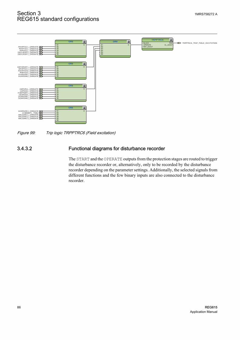
OR6B1B2B3B4B5B6
O
OR6B1B2B3B4B5B6
O
OR6B1B2B3B4B5B6
O
OR6B1B2B3B4B5B6
O
OR6B1B2B3B4B5B6
O
TRPPTRC6BLOCKOPERATERST_LKOUT
TRIPCL_LKOUT
TRPPTRC6_TRIP_FIELD_EXCITATION
CCBRBRF1_TRBU
PHHPTOC1_OPERATEPHIPTOC1_OPERATEPHPVOC1_OPERATE
DEFLPDEF2_OPERATEDEFLPDEF1_OPERATE
DEFHPDEF1_OPERATEEFHPTOC1_OPERATEROVPTOV2_OPERATE
PHPTOV2_OPERATE
OEPVPH1_OPERATE
H3EFPSEF1_OPERATE
DUPPDPR1_OPERATEDUPPDPR2_OPERATE
UEXPDIS1_OPERATE
UZPDIS1_OPERATE
DOPPDPR1_OPERATEDOPPDPR2_OPERATE
DOPPDPR3_OPERATE
ARCSARC1_OPERATEARCSARC2_OPERATEARCSARC3_OPERATE
GUID-BBE9C4CA-E5E3-4BE2-A00E-ABCCCE0F4FC9 V2 EN
Figure 99: Trip logic TRPPTRC6 (Field excitation)
3.4.3.2 Functional diagrams for disturbance recorder
The START and the OPERATE outputs from the protection stages are routed to triggerthe disturbance recorder or, alternatively, only to be recorded by the disturbancerecorder depending on the parameter settings. Additionally, the selected signals fromdifferent functions and the few binary inputs are also connected to the disturbancerecorder.
Section 3 1MRS758272 AREG615 standard configurations
86 REG615Application Manual

RDRE1
RDRE
C1C2C3C4C5C6C7C8C9C10C11C12C13C14C15C16C17C18C19C20C21C22C23C24C25C26C27C28C29C30C31C32C33C34C35C36C37C38C39C40C41C42C43C44C45C46C47C48C49C50C51C52C53C54C55C56C57C58C59C60C61C62C63C64
TRIGGERED
OR6B1B2B3B4B5B6
O
OR6B1B2B3B4B5B6
O
ORB1B2
O
OR6B1B2B3B4B5B6
O
ORB1B2
O
ORB1B2
O
OR6B1B2B3B4B5B6
O
OR6B1B2B3B4B5B6
O
OR6B1B2B3B4B5B6
O
CCBRBRF1_TRBU
X110_BI7_CB_CLOSEDX110_BI8_CB_OPENED
PHLPTOC1_OPERATEPHHPTOC1_OPERATEPHIPTOC1_OPERATE
PHPVOC1_OPERATE
DEFLPDEF2_OPERATEDEFLPDEF1_OPERATE
DEFHPDEF1_OPERATE
EFHPTOC1_OPERATE
ROVPTOV1_OPERATEROVPTOV2_OPERATE
PHPTUV2_OPERATE
PHPTOV1_OPERATEPHPTOV2_OPERATE
PSPTUV2_OPERATE
NSPTOV2_OPERATE
FRPFRQ2_OPERATE
MNSPTOC1_OPERATEMNSPTOC2_OPERATE
OEPVPH1_OPERATE
H3EFPSEF1_OPERATE
DUPPDPR1_OPERATEDUPPDPR2_OPERATE
UEXPDIS1_OPERATEUZPDIS1_OPERATE
DOPPDPR1_OPERATEDOPPDPR2_OPERATEDOPPDPR3_OPERATE
FRPFRQ4_OPERATE
ARCSARC1_OPERATEARCSARC2_OPERATEARCSARC3_OPERATE
X130_BI2_EXT_TRIP2X130_BI1_EXT_TRIP1
CCBRBRF1_TRRET
FRPFRQ3_OPERATE
PHLPTOC1_STARTPHHPTOC1_STARTPHIPTOC1_STARTPHPVOC1_START
DEFLPDEF2_STARTDEFHPDEF1_STARTEFHPTOC1_START
ROVPTOV1_STARTROVPTOV2_START
FRPFRQ1_OPERATE
PHPTUV1_OPERATE
NSPTOV1_OPERATE
PSPTUV1_OPERATE
PHPTUV1_STARTPHPTUV2_START
PHPTOV1_STARTPHPTOV2_STARTFRPFRQ1_STARTFRPFRQ2_STARTFRPFRQ3_STARTFRPFRQ4_START
MNSPTOC1_STARTMNSPTOC2_START
OEPVPH1_STARTUZPDIS1_START
H3EFPSEF1_START
UEXPDIS1_START
DUPPDPR1_STARTDUPPDPR2_START
NSPTOV1_STARTNSPTOV2_STARTPSPTUV1_STARTPSPTUV2_START
T2PTTR1_START
DEFLPDEF1_START
DOPPDPR1_STARTDOPPDPR2_START
T2PTTR1_OPERATE
DOPPDPR3_START
INRPHAR1_BLK2H
SEQSPVC1_FUSEF_U
X130_BI4_FIELD_EXCITATION_OPEN
ARCSARC1_ARC_FLT_DETARCSARC2_ARC_FLT_DETARCSARC3_ARC_FLT_DET
SEQSPVC1_FUSEF_3PH
DISTURB_RECORD_TRIGGERED
GUID-33594DA5-23FE-426F-B57F-83319BAD81B7 V2 EN
Figure 100: Disturbance recorder
3.4.3.3 Functional diagrams for condition monitoring
The fuse failure supervision function SEQSPVC1 detects failures in the voltagemeasurement circuits. Failures, such as an open MCB, raise an alarm.
SEQSPVC1BLOCKCB_CLOSEDDISCON_OPENMINCB_OPEN
FUSEF_3PHFUSEF_UX110_BI7_CB_CLOSED SEQSPVC1_FUSEF_U
X110_BI1_TERMINAL_VT_MCB_OPEN
SEQSPVC1_FUSEF_3PH
GUID-7B1E78AE-386C-4798-B341-238067D0BA37 V2 EN
Figure 101: Fuse failure supervision function
Circuit-breaker condition monitoring SSCBR1 supervises the switch status based onthe connected binary input information and the measured current levels. SSCBR1introduces various supervision methods.
Set the parameters for SSCBR1 properly.
1MRS758272 A Section 3REG615 standard configurations
REG615 87Application Manual

SSCBR1BLOCKPOSOPENPOSCLOSEOPEN_CB_EXECLOSE_CB_EXEPRES_ALM_INPRES_LO_INSPR_CHR_STSPR_CHRRST_IPOWRST_CB_WEARRST_TRV_TRST_SPR_T
TRV_T_OP_ALMTRV_T_CL_ALMSPR_CHR_ALM
OPR_ALMOPR_LO
IPOW_ALMIPOW_LO
CB_LIFE_ALMMON_ALM
PRES_ALMPRES_LO
OPENPOSINVALIDPOSCLOSEPOS
CB_OPEN_COMMANDX110_BI7_CB_CLOSEDX110_BI8_CB_OPENED
X120_BI2_CB_SPRING_CHARGED
X120_BI1_GAS_PRESSURE_ALARM
SSCBR1_TRV_T_OP_ALMSSCBR1_TRV_T_CL_ALM
SSCBR1_IPOW_ALMSSCBR1_IPOW_LO
SSCBR1_MON_ALMCB_SPRING_DISCHARGED
SSCBR1_SPR_CHR_ALMSSCBR1_OPR_ALMSSCBR1_OPR_LO
SSCBR1_CB_LIFE_ALM
SSCBR1_PRES_ALMSSCBR1_PRES_LO
GUID-E0D9A49B-E2CE-4A89-A1CE-BB091245D028 V2 EN
Figure 102: Circuit breaker condition monitoring function
OR6B1B2B3B4B5B6
O
OR6B1B2B3B4B5B6
O
ORB1B2
O
SSCBR1_TRV_T_OP_ALMSSCBR1_TRV_T_CL_ALM
SSCBR1_IPOW_ALM
SSCBR1_IPOW_LO
SSCBR1_MON_ALM
SSCBR1_SPR_CHR_ALMSSCBR1_OPR_ALM
SSCBR1_OPR_LO
SSCBR1_CB_LIFE_ALM
SSCBR1_PRES_ALMSSCBR1_PRES_LO
SSCBR1_ALARMS
GUID-9CA6E0DD-75C5-412E-816A-0592DD4FAA26 V2 EN
Figure 103: Logic for circuit breaker monitoring alarm
NOTIN OUTX120_BI2_CB_SPRING_CHARGED CB_SPRING_DISCHARGED
GUID-F6EDBB79-897C-49E7-9254-D78FA0A81155 V2 EN
Figure 104: Logic for start of circuit breaker spring charging
Two separate trip circuit supervision functions are included: TCSSCBR1 for poweroutput X100:PO3 and TCSSCBR2 for power output X100:PO4. TCSSCBR1 functionis blocked by the master trip TRPPTRC1 and TRPPTRC2 and the generator circuitbreaker open signal, whereas TCSSCBR2 function is blocked by the master tripTRPPTRC6 and the field excitation open signal.
It is assumed that there is no external resistor in the circuit breakertripping coil circuit connected in parallel with the circuit breaker'snormally open auxiliary contact.
Set the parameters for TCSSCBR1 properly.
Section 3 1MRS758272 AREG615 standard configurations
88 REG615Application Manual

TCSSCBR1BLOCK ALARM
TCSSCBR2BLOCK ALARM
ORB1B2
O
TCSSCBR1_BLOCKING TCSSCBR1_ALARM
TCSSCBR1_ALARM
TCSSCBR2_ALARM
TCSSCBR2_ALARM
TCSSCBR2_BLOCKING
TCSSCBR_ALARM
GUID-202136AA-1650-4285-812F-9331A28B90EB V2 EN
Figure 105: Trip circuit supervision function
OR6B1B2B3B4B5B6
OTRPPTRC2_TRIP
X110_BI8_CB_OPENED
TRPPTRC1_TRIP TCSSCBR1_BLOCKING
GUID-905F85C5-4D92-4162-AFD2-6FD2035FF732 V2 EN
Figure 106: Logic for blocking of trip circuit supervision
Runtime counter for machines and devices MDSOPT provides history data since thelast commissioning. The counter counts the total number of generator running hoursand is incremented when the energizing circuit breaker is closed.
MDSOPT1BLOCKPOS_ACTIVERESET
ALARMWARNINGX110_BI7_CB_CLOSED
MDSOPT1_ALARM
GUID-BE2212C3-3234-4CE4-BF91-820C7D385EEC V2 EN
Figure 107: Generator runtime counter
3.4.3.4 Functional diagrams for control and interlocking
Two types of disconnector and earthing switch function blocks are available.DCSXSWI1...3 and ESSXSWI1...2 are status only type and DCXSWI1...2 andESXSWI1 are controllable type. By default, the status only blocks are connected in astandard configuration. The disconnector (CB truck) and line side earthing switchstatus information is connected to DCSXSWI1 and ESSXSI1.
DCSXSWI1POSOPENPOSCLOSE
OPENPOSCLOSEPOS
OKPOS
X110_BI4_CB_TRUCK_IN_TESTX110_BI3_CB_TRUCK_IN_SERVICE
GUID-9FC8A7FA-2AA4-4359-92D8-ED1FA0B7E9D0 V2 EN
Figure 108: Disconnector control logic
1MRS758272 A Section 3REG615 standard configurations
REG615 89Application Manual

ESSXSWI1POSOPENPOSCLOSE
OPENPOSCLOSEPOS
OKPOS
X110_BI6_ES1_OPENEDX110_BI5_ES1_CLOSED
GUID-DEACDD18-8FBF-4AE8-80B1-EF93821D8E51 V2 EN
Figure 109: Earth switch control logic
The circuit breaker closing is disabled by default, as in case of generator, the closingof the circuit breaker is done by a special synchronizer device.
The OKPOS output from DCSXSWI defines whether the disconnector or breakertruck is open (in test position) or closed (in service position). This output, togetherwith the open earth switch and non-active trip signals, activates the close-enablesignal to the circuit breaker control function block. The open operation for circuitbreaker is always enabled.
Connect the additional signals required for the application for openingof circuit breaker.
CBXCBR1POSOPENPOSCLOSEENA_OPENENA_CLOSEBLK_OPENBLK_CLOSEAU_OPENAU_CLOSETRIPSYNC_OKSYNC_ITL_BYP
SELECTEDEXE_OPEXE_CL
OP_REQCL_REQ
OPENPOSCLOSEPOS
OKPOSOPEN_ENAD
CLOSE_ENAD
TRUEX110_BI7_CB_CLOSEDX110_BI8_CB_OPENED
CBXCBR1_EXE_OP
FALSEFALSE
CBXCBR1_AU_OPEN
GUID-A857DA54-6BF9-4BB1-AD18-99B0387B9015 V2 EN
Figure 110: Circuit breaker 1 control logic
OR6B1B2B3B4B5B6
O CB_OPEN_COMMANDTRPPTRC1_TRIPCBXCBR1_EXE_OP
GUID-70DB34F4-F3D2-4FAA-908E-DAE8AF653E65 V2 EN
Figure 111: Signal for opening coil of circuit breaker 1
The configuration includes the logic for generating circuit breaker external openingcommand with the relay in local or remote mode.
Connect additional signals for opening of circuit breaker in local orremote mode, if applicable for the configuration.
Section 3 1MRS758272 AREG615 standard configurations
90 REG615Application Manual

ANDB1B2
O
ANDB1B2
O
ORB1B2
O
FALSE
FALSE
CONTROL_LOCAL
CONTROL_REMOTE
CBXCBR1_AU_OPEN
GUID-39E32323-F206-41CB-9140-3C148E75CD09 V2 EN
Figure 112: External opening command for circuit breaker 1
3.4.3.5 Functional diagram for measurement functions
The phase current inputs to the relay are measured by the three-phase currentmeasurement function CMMXU1. The three-phase current input is connected to theX120 card in the back panel. The sequence current measurement CSMSQI1 measuresthe sequence current and the residual current measurement RESCMMXU1 measuresthe residual current.
The three-phase terminal side voltage inputs to the relay are measured by the three-phase voltage measurement function VMMXU1. In addition to phase voltage,terminal side and neutral side residual voltage are measured by residual voltagemeasurement RESVMMXU1 and RESVMMXU2. The three-phase voltage input aswell as residual voltages are connected to the X130 card in the back panel. Thesequence voltage measurement VSMSQI1 measures the sequence voltage.
The measurements can be seen in the LHMI and they are available under themeasurement option in the menu selection. Based on the settings, function blocks cangenerate low alarm or warning and high alarm or warning signals for the measuredcurrent values.
The frequency measurement FMMXU1 of the power system and three-phase powerand energy measurement PEMMXU1 are available. Load profile record LDPRLRC1is included in the measurements sheet. LDPRLRC1 offers the ability to observe theloading history of the corresponding feeder.
CMMXU1BLOCK HIGH_ALARM
HIGH_WARNLOW_WARN
LOW_ALARM
GUID-808ADD59-F47E-4B78-B3E0-2DC325894287 V2 EN
Figure 113: Current measurement: Three-phase current measurement
CSMSQI1
GUID-4938BE4F-F61D-4B6E-AC06-C77D5DD06B05 V2 EN
Figure 114: Current measurement: Sequence current measurement
1MRS758272 A Section 3REG615 standard configurations
REG615 91Application Manual

RESCMMXU1BLOCK HIGH_ALARM
HIGH_WARN
GUID-9963B5D7-2FD2-4805-9030-0939238C1244 V2 EN
Figure 115: Current measurement: Residual current measurement
VMMXU1BLOCK HIGH_ALARM
HIGH_WARNLOW_WARN
LOW_ALARM
GUID-97F2D59A-5336-4998-BEBC-4B6D8FA414FB V2 EN
Figure 116: Voltage measurement: Three-phase voltage measurement
VSMSQI1
GUID-A11531DF-4DB4-400E-9C74-FF6DC3EF5C31 V2 EN
Figure 117: Voltage measurement: Sequence voltage measurement
RESVMMXU1BLOCK HIGH_ALARM
HIGH_WARN
GUID-915B8EDA-2F27-43E3-8671-49CB8A7C5279 V2 EN
Figure 118: Voltage measurement: Residual voltage measurement (Terminalside)
RESVMMXU2BLOCK HIGH_ALARM
HIGH_WARN
GUID-ACFD934B-DC51-4E20-A8A7-150B1C557721 V2 EN
Figure 119: Voltage measurement: Residual voltage measurement (Neutralside)
FMMXU1
GUID-40D7B24E-9CED-44A0-8123-F527F32ABCFA V2 EN
Figure 120: Other measurement: Frequency measurement
PEMMXU1RSTACM
GUID-BB48899A-D525-4CC0-A8B3-64210B8CC378 V2 EN
Figure 121: Other measurement: Three phase power and energy measurement
Section 3 1MRS758272 AREG615 standard configurations
92 REG615Application Manual

FLTRFRC1BLOCKCB_CLRD
GUID-1168DAAD-A764-4B36-9C6D-B7727E56CC7A V2 EN
Figure 122: Other measurement: Data monitoring
LDPRLRC1RSTMEM MEM_WARN
MEM_ALARM
GUID-98F5BB14-5D85-4061-83F8-71D79D53ED71 V2 EN
Figure 123: Other measurement: Load profile record
1MRS758272 A Section 3REG615 standard configurations
REG615 93Application Manual

3.4.3.6 Functional diagrams for IOs and alarm LEDs
ORB1B2
O
ORB1B2
O
ORB1B2
O
ORB1B2
O
ORB1B2
O
ORB1B2
O
ORB1B2
O
ORB1B2
O
X110_BI7_CB_CLOSED
X110_BI8_CB_OPENED
X110_BI4_CB_TRUCK_IN_TEST
X110_BI3_CB_TRUCK_IN_SERVICE
X110_BI6_ES1_OPENED
X110_BI5_ES1_CLOSED
X110_BI2_NEUTRAL_VT_MCB_OPEN
X110_BI1_TERMINAL_VT_MCB_OPEN
X110 (BIO)_110.X110-Input 6
X110 (BIO-H)_110.X110-Input 5
X110 (BIO)_110.X110-Input 5
X110 (BIO-H)_110.X110-Input 1
X110 (BIO)_110.X110-Input 8
X110 (BIO)_110.X110-Input 4
X110 (BIO-H)_110.X110-Input 8
X110 (BIO)_110.X110-Input 7
X110 (BIO-H)_110.X110-Input 2
X110 (BIO)_110.X110-Input 1
X110 (BIO-H)_110.X110-Input 3
X110 (BIO-H)_110.X110-Input 4
X110 (BIO)_110.X110-Input 3
X110 (BIO)_110.X110-Input 2
X110 (BIO-H)_110.X110-Input 7
X110 (BIO-H)_110.X110-Input 6
GUID-72B4EA71-12BC-41AB-B455-4A111F24533C V2 EN
Figure 124: Default binary input - X110
X120_BI2_CB_SPRING_CHARGED
X120_BI1_GAS_PRESSURE_ALARM
X120 (AIM)_120.X120-Input 1
X120 (AIM)_120.X120-Input 2GUID-B07396A5-C919-47D3-9986-30A97673C0C1 V2 EN
Figure 125: Default binary input - X120
Section 3 1MRS758272 AREG615 standard configurations
94 REG615Application Manual

X130_BI3_RST_LOCKOUT
X130_BI2_EXT_TRIP2
X130_BI1_EXT_TRIP1
X130_BI4_FIELD_EXCITATION_OPEN
X130 (AIM)_130.X130-Input 1
X130 (AIM)_130.X130-Input 2
X130 (AIM)_130.X130-Input 3
X130 (AIM)_130.X130-Input 4GUID-9E29D059-7614-4DBB-9054-9838E54D7995 V2 EN
Figure 126: Default binary input - X130
CB_OPEN_COMMAND
GENERAL_OPERATE_PULSE
PRIMEMOVER_SHUTDOWN_PULSE
TRPPTRC6_TRIP_FIELD_EXCITATION
TRPPTRC2_TRIP
CCBRBRF1_TRBU
X100 (PSM)_100.X100-PO1
X100 (PSM)_100.X100-PO2
X100 (PSM)_100.X100-PO3
X100 (PSM)_100.X100-PO4
X100 (PSM)_100.X100-SO1
X100 (PSM)_100.X100-SO2
GUID-81CE1ADB-0FD2-4018-83A1-EC7D7B833DE9 V2 EN
Figure 127: Default binary output - X100
1MRS758272 A Section 3REG615 standard configurations
REG615 95Application Manual

TRPPTRC3_TRIP
TRPPTRC4_TRIP
TRPPTRC5_TRIP
OC_OPERATE_PULSE
EF_OPERATE_PULSE
VOLTAGE_AND_FREQ_OPERATE_PULSE
THERMAL_AND_NEQSEQ_OPERATE_PULSE
X110 (BIO-H)_110.X110-HSO1
X110 (BIO-H)_110.X110-HSO2
X110 (BIO-H)_110.X110-HSO3
X110 (BIO)_110.X110-SO1
X110 (BIO)_110.X110-SO2
X110 (BIO)_110.X110-SO3
X110 (BIO)_110.X110-SO4GUID-DBF72C4E-D03F-4AD9-9019-AD7D26D9799B V2 EN
Figure 128: Default binary output - X110
Section 3 1MRS758272 AREG615 standard configurations
96 REG615Application Manual

LED1OKALARMRESET
LED2OKALARMRESET
LED3OKALARMRESET
LED4OKALARMRESET
LED5OKALARMRESET
ORB1B2
O
OR6B1B2B3B4B5B6
O
ORB1B2
O
PHPVOC1_OPERATE
H3EFPSEF1_OPERATE
UEXPDIS1_OPERATE
UZPDIS1_OPERATE
PHxPTOC_OPERATE
EF_OPERATEROVPTOV_OPERATE
DOPPDPR_OPERATEDUPPDPR_OPERATE
GUID-68A7B757-5A34-4D33-B08E-4A6E29B21A97 V2 EN
1MRS758272 A Section 3REG615 standard configurations
REG615 97Application Manual

LED6OKALARMRESET
LED7OKALARMRESET
LED8OKALARMRESET
LED9OKALARMRESET
LED10OKALARMRESET
LED11OKALARMRESET
OR6B1B2B3B4B5B6
O
OR6B1B2B3B4B5B6
O
ORB1B2
O
CCBRBRF1_TRBU
T2PTTR1_OPERATE
SEQSPVC1_FUSEF_U
PSPTUV_OPERATENSPTOV_OPERATEPHPTOV_OPERATEPHPTUV_OPERATE
FREQUENCY_OPERATE
MNSPTOC_OPERATE
TCSSCBR_ALARMSSCBR1_ALARMS
DISTURB_RECORD_TRIGGERED
ARC_OPERATE
MDSOPT1_ALARM
GUID-89B38596-633C-4B1A-A6C3-F9DF1B654F4A V2 EN
Figure 129: Default LED connection
3.4.3.7 Functional diagram for other timer logics
The configuration includes overcurrent operate, earth-fault operate, voltage andfrequency operate, interconnected protection operate, prime mover shutdown logic,blocking logic for undervoltage protection and frequency protection and logic todisable directional underpower protection. The operate logics are connected tominimum pulse timer TPGAPC for setting the minimum pulse length for the outputs.The output from TPGAPC is connected to the binary outputs.
Section 3 1MRS758272 AREG615 standard configurations
98 REG615Application Manual

TPGAPC2IN1IN2
OUT1OUT2
ORB1B2
O
OR6B1B2B3B4B5B6
O
OC_OPERATE_PULSEEF_OPERATE_PULSEPHPVOC1_OPERATE
H3EFPSEF1_OPERATE
PHxPTOC_OPERATE
EF_OPERATEROVPTOV_OPERATE
GUID-A28A3528-1EB1-43D5-8984-0E22EDA9E06C V2 EN
Figure 130: Timer logic for overcurrent and earth-fault operate pulse
TPGAPC3IN1IN2
OUT1OUT2
OR6B1B2B3B4B5B6
O
ORB1B2
O
VOLTAGE_AND_FREQ_OPERATE_PULSETHERMAL_AND_NEQSEQ_OPERATE_PULSE
T2PTTR1_OPERATE
PSPTUV_OPERATENSPTOV_OPERATEPHPTOV_OPERATEPHPTUV_OPERATE
FREQUENCY_OPERATE
MNSPTOC_OPERATE
GUID-A89CCDFC-495A-486E-BEE1-8DA7105ABE9C V2 EN
Figure 131: Timer logic for voltage/frequency and interconnected protectionoperate pulse
OR6B1B2B3B4B5B6
O
OR6B1B2B3B4B5B6
O
OR6B1B2B3B4B5B6
O
TPGAPC4(TP(4))IN1IN2
OUT1OUT2
OR6B1B2B3B4B5B6
O PRIMEMOVER_SHUTDOWN_PULSE
CCBRBRF1_TRBU
PHHPTOC1_OPERATEPHIPTOC1_OPERATE
PHPVOC1_OPERATEDEFLPDEF2_OPERATEDEFLPDEF1_OPERATEDEFHPDEF1_OPERATE
EFHPTOC1_OPERATE
ROVPTOV2_OPERATEH3EFPSEF1_OPERATE
DUPPDPR1_OPERATEDUPPDPR2_OPERATE
UZPDIS1_OPERATEARCSARC1_OPERATEARCSARC2_OPERATEARCSARC3_OPERATE
GUID-2CAB4E88-BB61-4862-B356-D4AAD68679FF V2 EN
Figure 132: Timer logic for primemover shutdown pulse
ORB1B2
O
ANDB1B2
OX110_BI8_CB_OPENEDX110_BI3_CB_TRUCK_IN_SERVICE
SEQSPVC1_FUSEF_U BLOCK_UV
GUID-43B2CA5F-C90A-4DBA-9982-F4C311C16A59 V2 EN
Figure 133: Blocking logic for undervoltage protection
ANDB1B2
OX110_BI8_CB_OPENEDX110_BI3_CB_TRUCK_IN_SERVICE
BLOCK_FREQ
GUID-8B7B2E27-D2AB-486C-BDC3-E0E0B007B84E V2 EN
Figure 134: Blocking logic for frequency protection
1MRS758272 A Section 3REG615 standard configurations
REG615 99Application Manual

NOTIN OUTX110_BI7_CB_CLOSED CB_NOT_CLOSED
GUID-4249C362-88DE-4281-9DD8-3633E2294F15 V2 EN
Figure 135: Disable logic for directional underpower protection
3.4.3.8 Other functions
The configuration includes 18 instances of multipurpose protection MAPGAPC,power quality functions, two more instances of frequency protection and differenttypes of timers and control functions. These functions are not included in theapplication configuration but they can be added based on the system requirements.
3.5 Standard configuration D
3.5.1 Applications
The standard configuration with differential protection for machines, powerprotection, overcurrent protection, voltage and frequency based protection,underexcitation and out-of-step protection is mainly intended for the main protectionfor a small size synchronous power generator or as backup protection for a mediumsize synchronous power generator.
Standard configuration D is not designed for using all the available functionalitycontent in one relay at the same time. Three-phase directional overcurrent protection,three-phase voltage protection, positive-sequence and negative-sequence voltageprotection functions must be added with the Application Configuration tool. Toensure the performance of the relay, the user-specific configuration load is verifiedwith the Application Configuration tool in PCM600.
The IED with a standard configuration is delivered from the factory with defaultsettings and parameters. The end user flexibility for incoming, outgoing and internalsignal designation within the IED enables this configuration to be further adapted todifferent primary circuit layouts and the related functionality needs by modifying theinternal functionality using PCM600.
Section 3 1MRS758272 AREG615 standard configurations
100 REG615Application Manual

3.5.2 Functions
CONTROL AND INDICATION 1)
Object Ctrl 2) Ind 3)
CB
DC
ES1) Check availability of binary inputs/outputs from technical documentationControl and indication function for primary objectStatus indication function forprimary object
2)
3)
1 -
2 3
1 2
SYNC25
U12
UL1, L2, L3
3dl>G87G
Uo>59G
2×
ARC50L/50NL
3I>>>50P/51P
3I2f>68
3I>/Io>BF51BF/51NBF
P>/Q>32R/32O
3×
3I>51P-1
3I>>51P-2
I2>M46M
X<40
P<32U
2×
3Ith>T/G/C49T/G/C
3I(U)>51V
Io>>51N-2
G
GENERATOR PROTECTION RELAY STANDARD CONFIGURATION
PROTECTION LOCAL HMI
RL
ClearESCI
O
Configuration ASystemHMITimeAuthorization
RL
ClearESCI
O
U12 0. 0 kVP 0.00 kWQ 0.00 kVAr
IL2 0 A
A
Io
REMARKS
Optionalfunction
No. ofinstances
Alternative function to be defined when ordering
OR
Io/Uo
Calculatedvalue
3×
REG615 D
ALSO AVAILABLE
- Disturbance and fault recorders- Event log and recorded data- High-Speed Output module (optional)- Local/Remote push button on LHMI- Self-supervision - Time synchronization: IEEE 1588 v2,
SNTP, IRIG-B- User management- Web HMI
TCSTCM
OPTSOPTM
2×
FUSEF60
CBCMCBCM
CONDITION MONITORING AND SUPERVISION
COMMUNICATION
Protocols: IEC 61850-8-1/-9-2LE Modbus®
IEC 60870-5-103 DNP3Interfaces: Ethernet: TX (RJ45), FX (LC) Serial: Serial glass fiber (ST), RS-485, RS-232Redundant protocols: HSR PRP RSTP
3I
3I
UL1, L2, L3
Io
Master TripLockout relay
94/86
Io>→67N-1
Io>>→67N-2
2×
U12
Uo
MEASUREMENT
- I, U, Io, Uo, P, Q, E, pf, f- Limit value supervision- Load profile record- RTD/mA measurement (optional)- Symmetrical components- Frequency adaptivity
7
5
Analog interface types 1)
Current transformer
Voltage transformer1) Conventional transformer inputs
PQM3UPQM3V
PQMUPQMV
PQM3IPQM3I
2×RTD1×mA
MAPMAP
18×
3×
ORAND
3I>→67-1
3I>>→67-2
U2>47O-
U1<47U+
3U<27
2× 2×2×
3U>59
f>/f<,df/dt81
2×
U/f>24
3I
∆Io
Io
UL1, L2, L3
EXC.AVR
2×
Master TripLockout relay
94/86
Master TripLockout relay
94/86
3×2×
PQUUBPQVUB
4×
2×
OOS78
GUID-309F67A9-5199-4215-95A7-7703EE262635 V2 EN
Figure 136: Functionality overview for standard configuration D
3.5.2.1 Default I/O connections
Connector pins for each input and output are presented in the IED physicalconnections section.
1MRS758272 A Section 3REG615 standard configurations
REG615 101Application Manual

Table 21: Default connections for binary inputs
Binary input DescriptionX110-BI1 Terminal VT secondary MCB open
X110-BI2 Neutral VT secondary MCB open
X110-BI3 Circuit breaker truck in (service position) indication
X110-BI4 Circuit breaker truck out (test position) indication
X110-BI5 Earthing switch closed indication
X110-BI6 Earthing switch open indication
X110-BI7 Circuit breaker closed indication
X110-BI8 Circuit breaker open indication
X130-BI1 External trip 1
X130-BI2 External trip 2
X130-BI3 Lockout reset
X130-BI4 Field excitation open indication
Table 22: Default connections for binary outputs
Binary output DescriptionX100-PO1 Generator circuit breaker open command/trip 2
X100-PO2 Breaker failure backup trip to upstream breaker
X100-SO1 Prime mover shutdown
X100-SO2 General protection operate indication
X100-PO3 Generator circuit breaker open command/trip 1
X100-PO4 Field excitation circuit breaker open command
X110-SO1 In synchronism for closing
X110-SO2 Differential protection operated
X110-SO3 Frequency protection operated
X110-SO4 Thermal overload of NPS protection operated
X110-HSO1 Arc protection instance 1 operate activated
X110-HSO2 Arc protection instance 2 operate activated
X110-HSO3 Arc protection instance 3 operate activated
Table 23: Default connections for LEDs
LED Description1 Differential protection operated
2 Power protection operated
3 Overcurrent protection operated
4 Earth-fault protection operated
5 Synchronism or energization check OK
6 Frequency protection operated
Table continues on next page
Section 3 1MRS758272 AREG615 standard configurations
102 REG615Application Manual

LED Description7 Thermal overload of NPS protection operated
8 Disturbance recorder triggered
9 Supervision alarms
10 Arc fault detected
11 Circuit breaker failure protection operated
3.5.2.2 Default disturbance recorder settings
Table 24: Default disturbance recorder analog channels
Channel Description1 IL1
2 IL2
3 IL3
4 IL1B
5 IL2B
6 IL3B
7 Io
8 Uo
9 U1
10 U2
11 U3
12 U1B
Table 25: Default disturbance recorder binary channels
Channel ID text Level trigger mode1 PHLPTOC1 - start Positive or Rising
2 PHHPTOC1 - start Positive or Rising
3 PHIPTOC2 - start Positive or Rising
4 PHPVOC1 - start Positive or Rising
8 DEFLPDEF1 - start Positive or Rising
9 DEFLPDEF2 - start Positive or Rising
10 DEFHPDEF1 - start Positive or Rising
11 EFHPTOC1 - start Positive or Rising
12 MNSPTOC1 - start Positive or Rising
13 MNSPTOC2 - start Positive or Rising
18 DOPPDPR1 - start Positive or Rising
19 DOPPDPR2 - start Positive or Rising
21 DUPPDPR1 - start Positive or Rising
22 DUPPDPR2 - start Positive or Rising
Table continues on next page
1MRS758272 A Section 3REG615 standard configurations
REG615 103Application Manual
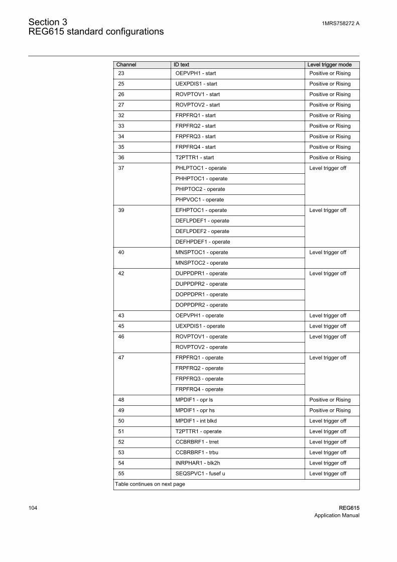
Channel ID text Level trigger mode23 OEPVPH1 - start Positive or Rising
25 UEXPDIS1 - start Positive or Rising
26 ROVPTOV1 - start Positive or Rising
27 ROVPTOV2 - start Positive or Rising
32 FRPFRQ1 - start Positive or Rising
33 FRPFRQ2 - start Positive or Rising
34 FRPFRQ3 - start Positive or Rising
35 FRPFRQ4 - start Positive or Rising
36 T2PTTR1 - start Positive or Rising
37 PHLPTOC1 - operate Level trigger off
PHHPTOC1 - operate
PHIPTOC2 - operate
PHPVOC1 - operate
39 EFHPTOC1 - operate Level trigger off
DEFLPDEF1 - operate
DEFLPDEF2 - operate
DEFHPDEF1 - operate
40 MNSPTOC1 - operate Level trigger off
MNSPTOC2 - operate
42 DUPPDPR1 - operate Level trigger off
DUPPDPR2 - operate
DOPPDPR1 - operate
DOPPDPR2 - operate
43 OEPVPH1 - operate Level trigger off
45 UEXPDIS1 - operate Level trigger off
46 ROVPTOV1 - operate Level trigger off
ROVPTOV2 - operate
47 FRPFRQ1 - operate Level trigger off
FRPFRQ2 - operate
FRPFRQ3 - operate
FRPFRQ4 - operate
48 MPDIF1 - opr ls Positive or Rising
49 MPDIF1 - opr hs Positive or Rising
50 MPDIF1 - int blkd Level trigger off
51 T2PTTR1 - operate Level trigger off
52 CCBRBRF1 - trret Level trigger off
53 CCBRBRF1 - trbu Level trigger off
54 INRPHAR1 - blk2h Level trigger off
55 SEQSPVC1 - fusef u Level trigger off
Table continues on next page
Section 3 1MRS758272 AREG615 standard configurations
104 REG615Application Manual

Channel ID text Level trigger mode56 X130BI1 - Ext trip1 Positive or Rising
57 X130BI2 - Ext trip2 Positive or Rising
58 X130BI4 - Field excitation open Positive or Rising
59 X110BI7 - CB closed Level trigger off
60 X110BI8 - CB open Level trigger off
61 ARCSARC1 - ARC flt det Level trigger off
ARCSARC2 - ARC flt det
ARCSARC3 - ARC flt det
62 ARCSARC1 - operate Positive or Rising
63 ARCSARC2 - operate Positive or Rising
64 ARCSARC3 - operate Positive or Rising
3.5.3 Functional diagrams
The functional diagrams describe the default input, output, alarm LED and function-to-function connections. The default connections can be viewed and changed withPCM600 according to the application requirements.
The analog channels have fixed connections to the different function blocks inside theIED’s standard configuration. However, the 12 analog channels available for thedisturbance recorder function are freely selectable as a part of the disturbancerecorder’s parameter settings.
The analog channels are assigned to different functions. The phase currents to the IEDare fed from a current transformer. The common signal marked with 3I represents thethree phase currents of the neutral side of the generator and 3IB represents the threephase currents of the terminal side of the generator. It is assumed that the core balanceCT is provided both on line and neutral side of the generator and are connected suchthat the differential residual current is fed to the IED.
The terminal side phase voltages to the IED are fed from a voltage transformer. Theresidual voltage to the IED is fed from either residually connected VTs, an open deltaconnected VT or internally calculated.
The IED offers six different settings groups which can be set based on individualneeds. Each group can be activated or deactivated using the setting group settingsavailable in the IED.
Depending on the communication protocol the required function block needs to beinitiated in the configuration. The Application Configuration tool also includes fixedBoolean signals TRUE and FALSE which can be used according to the applicationneeds.
1MRS758272 A Section 3REG615 standard configurations
REG615 105Application Manual

3.5.3.1 Functional diagrams for protection
The functional diagrams describe the protection functionality of the relay in detail andaccording to the factory set default connections.
Three non-directional and two directional overcurrent stages are offered for detectingphase faults in generators. In addition, one instance of voltage-dependent overcurrentprotection is also provided which can be used as a backup protection against phasefaults. During certain conditions, the fault current for three-phase faults may be lessthan full load current of the generator. This may not get noticed by phase overcurrentprotection, but the fault causes generator terminal voltage to drop. Voltage dependentovercurrent protection can be used to detect and operate such faults.
PHIPTOC1BLOCKENA_MULT
OPERATESTART
PHLPTOC1BLOCKENA_MULT
OPERATESTART
PHHPTOC1BLOCKENA_MULT
OPERATESTART
OR6B1B2B3B4B5B6
O
PHLPTOC1_OPERATE
PHLPTOC1_OPERATE
PHHPTOC1_OPERATE
PHHPTOC1_OPERATE
PHIPTOC1_OPERATE
PHIPTOC1_OPERATE
PHLPTOC1_START
PHHPTOC1_START
PHIPTOC1_START
INRPHAR1_BLK2H
INRPHAR1_BLK2H
PHxPTOC_OPERATE
GUID-610CEE81-AAC6-4973-AED7-471797835790 V2 EN
Figure 137: Non directional overcurrent protection function
PHPVOC1BLOCKENA_MULTENA_LOW_LIM
OPERATESTART
PHPVOC1_OPERATEPHPVOC1_START
SEQSPVC1_FUSEF_U
GUID-65AF5BBF-1F2B-482A-8377-880F152EBABE V2 EN
Figure 138: Voltage dependent overcurrent protection function
The output BLK2H of three-phase inrush detector INRPHAR1 either blocks thefunction or multiplies the active settings for any of the available overcurrent or earth-fault function blocks. In the configuration, INRPHAR1 blocks the high andinstantaneous stage of non-directional overcurrent protection.
Section 3 1MRS758272 AREG615 standard configurations
106 REG615Application Manual

INRPHAR1BLOCK BLK2H INRPHAR1_BLK2H
GUID-6F446DFB-110D-4271-A44E-4CC01FE8AEBE V2 EN
Figure 139: Inrush detector function
Two negative-sequence overcurrent protection stages MNSPTOC1 and MNSPTOC2are provided for phase unbalance protection. These functions are used to protectagainst unbalance conditions due to unbalance load or unsymmetrical faults.
MNSPTOC1BLOCK OPERATE
STARTBLK_RESTART
MNSPTOC2BLOCK OPERATE
STARTBLK_RESTART
ORB1B2
O
MNSPTOC1_OPERATE
MNSPTOC1_OPERATE
MNSPTOC2_OPERATE
MNSPTOC2_OPERATE
MNSPTOC1_START
MNSPTOC2_START
MNSPTOC_OPERATE
GUID-EA221211-DF98-4E50-95C1-D7399B66EBE6 V2 EN
Figure 140: Negative sequence overcurrent protection function
One non-directional sensitive earth-fault stage EFHPTOC1 and three directionalearth-fault stages DEFxPDEF are offered for providing primary and backupprotection for generator earth-fault protection. Transient/intermittent earth-faultprotection INTRPTEF is used for transient-based earth-fault protection.
DEFHPDEF1BLOCKENA_MULTRCA_CTL
OPERATESTART
DEFLPDEF1BLOCKENA_MULTRCA_CTL
OPERATESTART
DEFLPDEF2BLOCKENA_MULTRCA_CTL
OPERATESTART
DEFLPDEF2_OPERATE
DEFLPDEF1_OPERATE
DEFHPDEF1_OPERATE
DEFLPDEF2_START
DEFHPDEF1_START
DEFLPDEF1_START
GUID-9DE28768-8BFD-4302-877D-AD11F566A1C4 V2 EN
Figure 141: Directional earth-fault protection function
1MRS758272 A Section 3REG615 standard configurations
REG615 107Application Manual

EFHPTOC1BLOCKENA_MULT
OPERATESTART
OR6B1B2B3B4B5B6
ODEFLPDEF2_OPERATEDEFLPDEF1_OPERATE
DEFHPDEF1_OPERATE
EFHPTOC1_OPERATE
EFHPTOC1_OPERATE
EFHPTOC1_START
EF_OPERATE
GUID-675CC226-1A1F-4706-B718-9E94A3D9CD1A V2 EN
Figure 142: Earth-fault protection function
Three-phase thermal overload protection, two time constants, T2PTTR1 detectscontinuous overloading conditions preventing excessive insulation damage in thelong run.
T2PTTR1BLOCKAMB_TEMP
OPERATESTARTALARM
BLK_CLOSE
T2PTTR1_STARTT2PTTR1_OPERATE
GUID-520542E6-D29F-4B15-92ED-D81AA8886898 V2 EN
Figure 143: Thermal overcurrent protection function
The stabilized and instantaneous differential protection for machines MPDIF1provides protection against internal failures. The relay compares the phase currents onboth sides of the generator to be protected. If the differential current of the phasecurrents in one of the phases exceed the setting of the stabilized operationcharacteristic or the instantaneous protection stage of the function, the functionprovides an operating signal. The operating signal is connected to the master trip 1 and2, trip of field excitation and also to the alarm LED 1.
MPDIF1BLOCKBLK_OPR_LSBLK_OPR_HS
OPERATEOPR_LSOPR_HS
INT_BLKD
MPDIF1_OPERATEMPDIF1_OPR_LSMPDIF1_OPR_HSMPDIF1_INT_BLKD
GUID-4FF775E0-0594-49D2-8C53-E94DB19A533D V2 EN
Figure 144: Differential protection function
Circuit breaker failure protection CCBRBRF1 is initiated via the START input by anumber of different protection functions available in the relay. The breaker failureprotection function offers different operating modes associated with the circuitbreaker position and the measured phase and residual currents.
The circuit breaker failure protection function has two operating outputs: TRRET andTRBU. The TRRET operating output is used for retripping its own breaker throughTRPPTRC2_TRIP. The TRBU output gives a backup trip to the breaker feedingupstream. For this purpose, the TRBU operating output signal is connected to thebinary output X100:PO2. In addition, TRBU operating output is also used to trip fieldexcitation circuit breaker through TRPPTRC6_TRIP_FIELD EXCITATION.
Section 3 1MRS758272 AREG615 standard configurations
108 REG615Application Manual

CCBRBRF1BLOCKSTARTPOSCLOSECB_FAULT
CB_FAULT_ALTRBU
TRRET
OR6B1B2B3B4B5B6
O
OR6B1B2B3B4B5B6
O
OR6B1B2B3B4B5B6
O CCBRBRF1_TRBU
X110_BI7_CB_CLOSED
PHLPTOC1_OPERATEPHHPTOC1_OPERATEPHIPTOC1_OPERATEPHPVOC1_OPERATE
DEFLPDEF2_OPERATEDEFLPDEF1_OPERATE
DEFHPDEF1_OPERATEEFHPTOC1_OPERATE
MPDIF1_OPERATE
ARCSARC1_OPERATEARCSARC2_OPERATEARCSARC3_OPERATE
CCBRBRF1_TRRET
GUID-06DDC991-3146-40DC-B97C-EACF6694BE63 V2 EN
Figure 145: Circuit breaker failure protection function
Three arc protection ARCSARC1...3 stages are included as an optional function. Thearc protection offers individual function blocks for three arc sensors that can beconnected to the relay. Each arc protection function block has two different operationmodes, that is, with or without the phase and residual current check.
The operating signals from ARCSARC1...3 are connected to both generator circuitbreaker trip logic TRPPTRC1 and TRPPTRC2 and also to field excitation circuitbreaker trip logic TRPPTRC6. If the relay has been ordered with high speed binaryoutputs, the individual operating signals from ARCSARC1...3 are connected todedicated trip logic TRPPTRC3...5. The output of TRPPTRC3...5 is available at highspeed outputs X110:HSO1, X110:HSO2 and X110:HSO3.
OR6B1B2B3B4B5B6
O
ARCSARC1BLOCKREM_FLT_ARCOPR_MODE
OPERATEARC_FLT_DET
ARCSARC2BLOCKREM_FLT_ARCOPR_MODE
OPERATEARC_FLT_DET
ARCSARC3BLOCKREM_FLT_ARCOPR_MODE
OPERATEARC_FLT_DET
ARCSARC1_OPERATE
ARCSARC1_OPERATE
ARCSARC2_OPERATE
ARCSARC2_OPERATE
ARCSARC3_OPERATE
ARCSARC3_OPERATE
ARCSARC1_ARC_FLT_DET
ARCSARC2_ARC_FLT_DET
ARCSARC3_ARC_FLT_DET
ARC_OPERATE
GUID-07D95F37-C8C3-452D-87B7-14BE7FD7BC84 V2 EN
Figure 146: Arc protection function
1MRS758272 A Section 3REG615 standard configurations
REG615 109Application Manual

TRPPTRC3BLOCKOPERATERST_LKOUT
TRIPCL_LKOUT
TRPPTRC4BLOCKOPERATERST_LKOUT
TRIPCL_LKOUT
TRPPTRC5BLOCKOPERATERST_LKOUT
TRIPCL_LKOUT
TRPPTRC3_TRIP
TRPPTRC4_TRIP
TRPPTRC5_TRIP
X130_BI3_RST_LOCKOUT
X130_BI3_RST_LOCKOUT
X130_BI3_RST_LOCKOUT
ARCSARC1_OPERATE
ARCSARC2_OPERATE
ARCSARC3_OPERATE
GUID-00D88773-7C5C-4DE6-8A2C-2B5E85454E96 V2 EN
Figure 147: Arc protection with dedicated HSO
Residual overvoltage protection ROVPTOV provides protection against stator earthfaults from 5% to 100% of winding from neutral. Two instances of ROVPTOV areprovided.
ROVPTOV1BLOCK OPERATE
START
ROVPTOV2BLOCK OPERATE
START
ORB1B2
O
ROVPTOV1_OPERATE
ROVPTOV1_OPERATE
ROVPTOV2_OPERATE
ROVPTOV2_OPERATE
ROVPTOV1_START
ROVPTOV2_START
ROVPTOV_OPERATE
GUID-C2944708-E995-4BD7-B611-6CAC4BD0847E V2 EN
Figure 148: Residual overvoltage protection function
The selectable underfrequency or overfrequency or rate of change of frequencyprotection FRPFRQ prevents damage to network components under unwantedfrequency conditions. The function also contains a selectable rate of change of thefrequency (gradient) protection to detect an increase or decrease in the fast powersystem frequency at an early stage. This can be used as an early indication of adisturbance in the system. Configuration offers four instances of frequencyprotection, these instances can be configured to operate as underfrequency oroverfrequency or rate of change of frequency according to the system requirement.The frequency protection is blocked when generator CB is in open position.
Section 3 1MRS758272 AREG615 standard configurations
110 REG615Application Manual

FRPFRQ1BLOCK OPERATE
OPR_OFRQOPR_UFRQ
OPR_FRGSTART
ST_OFRQST_UFRQ
ST_FRG
FRPFRQ2BLOCK OPERATE
OPR_OFRQOPR_UFRQ
OPR_FRGSTART
ST_OFRQST_UFRQ
ST_FRG
FRPFRQ3BLOCK OPERATE
OPR_OFRQOPR_UFRQ
OPR_FRGSTART
ST_OFRQST_UFRQ
ST_FRG
FRPFRQ4BLOCK OPERATE
OPR_OFRQOPR_UFRQ
OPR_FRGSTART
ST_OFRQST_UFRQ
ST_FRG
OR6B1B2B3B4B5B6
O
FRPFRQ4_OPERATE
FRPFRQ4_OPERATE
FRPFRQ2_OPERATE
FRPFRQ2_OPERATE
FRPFRQ3_OPERATE
FRPFRQ3_OPERATE
FRPFRQ1_OPERATE
FRPFRQ1_OPERATE
FRPFRQ1_START
FRPFRQ2_START
FRPFRQ3_START
FRPFRQ4_START
BLOCK_FREQ
BLOCK_FREQ
BLOCK_FREQ
BLOCK_FREQ
FREQUENCY_OPERATE
GUID-005B0A0F-2310-4E3A-A1D2-026F0B469A35 V2 EN
Figure 149: Frequency protection function
Two instances of reverse power/directional overpower protection DOPPDPR areprovided to detect either loss of prime mover or detecting motoring action or detectingany abnormal high reactive power being absorbed by the generator.
1MRS758272 A Section 3REG615 standard configurations
REG615 111Application Manual

DOPPDPR1BLOCK OPERATE
START
DOPPDPR2BLOCK OPERATE
START
OR6B1B2B3B4B5B6
O
DOPPDPR1_OPERATE
DOPPDPR1_OPERATE
DOPPDPR2_OPERATE
DOPPDPR2_OPERATE
DOPPDPR1_START
DOPPDPR2_START
SEQSPVC1_FUSEF_U
SEQSPVC1_FUSEF_U
DOPPDPR_OPERATE
GUID-3446AB4B-0D02-4A64-A5DE-C53F29930B2C V2 EN
Figure 150: Directional overpower protection function
Two instances of underpower protection DUPPDPR are provided. Normally these areused in coordination with reverse active power protection.
DUPPDPR1BLOCKDISABLE
OPERATESTART
DUPPDPR2BLOCKDISABLE
OPERATESTART
ORB1B2
O
DUPPDPR1_OPERATE
DUPPDPR1_OPERATE
DUPPDPR2_OPERATE
DUPPDPR2_OPERATE
DUPPDPR1_START
DUPPDPR2_START
SEQSPVC1_FUSEF_U
SEQSPVC1_FUSEF_U
CB_NOT_CLOSED
CB_NOT_CLOSED
DUPPDPR_OPERATE
GUID-8E7C906F-A069-46E9-AC86-DAF689BC8F03 V2 EN
Figure 151: Directional underpower protection function
On losing excitation, generator may over speed and operate as an induction generatortaking reactive power from the system which may reduce system voltages. Three-phase underexcitation protection UEXPDIS is provided to detect such conditions.Directional underpower protection is disabled when the generator circuit breaker is inopen position.
UEXPDIS1BLOCKEXT_LOS_DET
OPERATESTART
UEXPDIS1_OPERATEUEXPDIS1_START
SEQSPVC1_FUSEF_UX130_BI4_FIELD_EXCITATION_OPEN
GUID-CA7946F0-0588-4A56-9310-F0024467EC40 V2 EN
Figure 152: Underexcitation protection function
Section 3 1MRS758272 AREG615 standard configurations
112 REG615Application Manual

Overexcitation protection OEPVPH is provided to protect the generator againstoverexcitation. Due to overexcitation, saturation of the magnetic core of generator andconnected transformer may occur, and stray flux may be induced in nonlaminatedcomponents that are not designed to carry flux. Excessive flux also causes excessiveeddy currents resulting into excessive voltage between laminations causingoverheating and damage to insulation.
OEPVPH1BLOCK OPERATE
STARTBLK_RESTARTCOOL_ACTIVE
OEPVPH1_OPERATEOEPVPH1_START
SEQSPVC1_FUSEF_U
GUID-151F93B0-B003-4817-8900-63991380915E V2 EN
Figure 153: Overexcitation protection function
General start and operate signals from all functions are connected to minimum pulsetimer TPGAPC1 for setting the minimum pulse length for the outputs. The outputfrom TPGAPC1 is connected to binary output.
1MRS758272 A Section 3REG615 standard configurations
REG615 113Application Manual

TPGAPC1(TP(1))IN1IN2
OUT1OUT2
OR6B1B2B3B4B5B6
O
OR6B1B2B3B4B5B6
O
OR6B1B2B3B4B5B6
O
OR6B1B2B3B4B5B6
O
OR6B1B2B3B4B5B6
O
OR6B1B2B3B4B5B6
O
OR6B1B2B3B4B5B6
O
OR6B1B2B3B4B5B6
O
OR6B1B2B3B4B5B6
O
OR6B1B2B3B4B5B6
O
OR6B1B2B3B4B5B6
O
GENERAL_OPERATE_PULSE
PHLPTOC1_OPERATEPHHPTOC1_OPERATEPHIPTOC1_OPERATEPHPVOC1_OPERATE
DEFLPDEF2_OPERATEDEFLPDEF1_OPERATE
DEFHPDEF1_OPERATEEFHPTOC1_OPERATEROVPTOV1_OPERATEROVPTOV2_OPERATE
MNSPTOC1_OPERATEMNSPTOC2_OPERATE
DUPPDPR1_OPERATEDUPPDPR2_OPERATE
DOPPDPR1_OPERATEDOPPDPR2_OPERATE
UEXPDIS1_OPERATE
MPDIF1_OPERATE
FRPFRQ1_OPERATEFRPFRQ2_OPERATEFRPFRQ3_OPERATEFRPFRQ4_OPERATE
OEPVPH1_OPERATE
X130_BI1_EXT_TRIP1X130_BI2_EXT_TRIP2
ARCSARC1_OPERATEARCSARC2_OPERATEARCSARC3_OPERATE
PHLPTOC1_STARTPHHPTOC1_STARTPHIPTOC1_STARTPHPVOC1_START
DEFLPDEF2_START
DEFHPDEF1_STARTEFHPTOC1_STARTROVPTOV1_STARTROVPTOV2_START
FRPFRQ1_STARTFRPFRQ2_STARTFRPFRQ3_STARTFRPFRQ4_START
MNSPTOC1_STARTMNSPTOC2_START
OEPVPH1_START
DEFLPDEF1_START
T2PTTR1_STARTUEXPDIS1_START
T2PTTR1_OPERATE
DUPPDPR1_STARTDUPPDPR2_START
DOPPDPR1_STARTDOPPDPR2_START
GUID-E510E8FA-7E5E-43A8-A698-4F91D4058C0C V2 EN
Figure 154: General start and operate signal
The operating signals from the protection functions are connected to the two triplogics TRPPTRC1 and TRPPTRC2. The output of these trip logic functions isavailable at binary outputs X100:PO3 and X100:PO1. The trip logic functions areprovided with a lockout and latching function, event generation and the trip signalduration setting. If the lockout operation mode is selected, binary input X130:BI3 hasbeen assigned to RST_LKOUT input of both the trip logic to enable external reset witha push button.
Three other trip logics TRPPTRC3...4 are also available if the relay is ordered withhigh speed binary output options.
Section 3 1MRS758272 AREG615 standard configurations
114 REG615Application Manual

In addition, trip logic TRPPTRC6 is available to trip the circuit breaker of filedexcitation. The protection function which should trip the field excitations areconnected to TRPPTRC6.
TRPPTRC1(MasterBLOCKOPERATERST_LKOUT
TRIPCL_LKOUT
OR6B1B2B3B4B5B6
O
OR6B1B2B3B4B5B6
O
OR6B1B2B3B4B5B6
O
OR6B1B2B3B4B5B6
O
OR6B1B2B3B4B5B6
O
OR6B1B2B3B4B5B6
O
TRPPTRC1_TRIPPHLPTOC1_OPERATEPHHPTOC1_OPERATEPHIPTOC1_OPERATEPHPVOC1_OPERATE
DEFLPDEF2_OPERATEDEFLPDEF1_OPERATE
DEFHPDEF1_OPERATEEFHPTOC1_OPERATEROVPTOV1_OPERATEROVPTOV2_OPERATE
MNSPTOC1_OPERATEMNSPTOC2_OPERATE
DUPPDPR1_OPERATEDUPPDPR2_OPERATE
X130_BI3_RST_LOCKOUT
DOPPDPR1_OPERATEDOPPDPR2_OPERATE
UEXPDIS1_OPERATE
MPDIF1_OPERATE
FRPFRQ1_OPERATEFRPFRQ2_OPERATEFRPFRQ3_OPERATEFRPFRQ4_OPERATE
OEPVPH1_OPERATE
X130_BI1_EXT_TRIP1X130_BI2_EXT_TRIP2
ARCSARC1_OPERATEARCSARC2_OPERATEARCSARC3_OPERATE
GUID-43E2D7FB-C367-4443-829B-7DFA506BD7CC V2 EN
Figure 155: Trip logic TRPPTRC1
1MRS758272 A Section 3REG615 standard configurations
REG615 115Application Manual

OR6B1B2B3B4B5B6
O
TRPPTRC2(MasterBLOCKOPERATERST_LKOUT
TRIPCL_LKOUT
OR6B1B2B3B4B5B6
O
OR6B1B2B3B4B5B6
O
OR6B1B2B3B4B5B6
O
OR6B1B2B3B4B5B6
O
OR6B1B2B3B4B5B6
O
TRPPTRC2_TRIPPHLPTOC1_OPERATEPHHPTOC1_OPERATEPHIPTOC1_OPERATEPHPVOC1_OPERATE
DEFLPDEF2_OPERATEDEFLPDEF1_OPERATE
DEFHPDEF1_OPERATEEFHPTOC1_OPERATEROVPTOV1_OPERATEROVPTOV2_OPERATE
MNSPTOC1_OPERATEMNSPTOC2_OPERATE
DUPPDPR1_OPERATEDUPPDPR2_OPERATE
X130_BI3_RST_LOCKOUT
DOPPDPR1_OPERATEDOPPDPR2_OPERATE
UEXPDIS1_OPERATE
MPDIF1_OPERATE
FRPFRQ1_OPERATEFRPFRQ2_OPERATEFRPFRQ3_OPERATEFRPFRQ4_OPERATE
OEPVPH1_OPERATE
X130_BI1_EXT_TRIP1X130_BI2_EXT_TRIP2
ARCSARC1_OPERATEARCSARC2_OPERATEARCSARC3_OPERATE
CCBRBRF1_TRRET
GUID-EFFDCE3C-152F-45AD-BE23-25C870C2F160 V2 EN
Figure 156: Trip logic TRPPTRC2
Section 3 1MRS758272 AREG615 standard configurations
116 REG615Application Manual

OR6B1B2B3B4B5B6
O
OR6B1B2B3B4B5B6
O
OR6B1B2B3B4B5B6
O
OR6B1B2B3B4B5B6
O
OR6B1B2B3B4B5B6
O
TRPPTRC6(MasterBLOCKOPERATERST_LKOUT
TRIPCL_LKOUT
TRPPTRC6_TRIP_FIELD_EXCITATION
CCBRBRF1_TRBU
PHHPTOC1_OPERATEPHIPTOC1_OPERATEPHPVOC1_OPERATE
DEFLPDEF2_OPERATEDEFLPDEF1_OPERATE
DEFHPDEF1_OPERATEEFHPTOC1_OPERATEROVPTOV2_OPERATE
DUPPDPR1_OPERATEDUPPDPR2_OPERATE
DOPPDPR1_OPERATEDOPPDPR2_OPERATE
UEXPDIS1_OPERATEMPDIF1_OPERATE
OEPVPH1_OPERATE
ARCSARC1_OPERATEARCSARC2_OPERATEARCSARC3_OPERATE
GUID-D70DED0B-5023-4822-9857-94E456C3AABD V1 EN
Figure 157: Trip logic TRPPTRC6 (Field excitation)
3.5.3.2 Functional diagrams for disturbance recorder
The START and the OPERATE outputs from the protection stages are routed to triggerthe disturbance recorder or, alternatively, only to be recorded by the disturbancerecorder depending on the parameter settings. Additionally, the selected signals fromdifferent functions and the few binary inputs are also connected to the disturbancerecorder.
1MRS758272 A Section 3REG615 standard configurations
REG615 117Application Manual

RDRE1
RDRE
C1C2C3C4C5C6C7C8C9C10C11C12C13C14C15C16C17C18C19C20C21C22C23C24C25C26C27C28C29C30C31C32C33C34C35C36C37C38C39C40C41C42C43C44C45C46C47C48C49C50C51C52C53C54C55C56C57C58C59C60C61C62C63C64
TRIGGERED
OR6B1B2B3B4B5B6
O
OR6B1B2B3B4B5B6
O
ORB1B2
O
OR6B1B2B3B4B5B6
O
OR6B1B2B3B4B5B6
O
OR6B1B2B3B4B5B6
O
ORB1B2
O
CCBRBRF1_TRBU
X110_BI8_CB_OPENEDX110_BI7_CB_CLOSED
PHLPTOC1_OPERATEPHHPTOC1_OPERATEPHIPTOC1_OPERATE
PHPVOC1_OPERATE
DEFLPDEF2_OPERATEDEFLPDEF1_OPERATE
DEFHPDEF1_OPERATE
EFHPTOC1_OPERATE
ROVPTOV1_OPERATEROVPTOV2_OPERATE
MNSPTOC1_OPERATEMNSPTOC2_OPERATE
DUPPDPR1_OPERATEDUPPDPR2_OPERATE
DOPPDPR1_OPERATEDOPPDPR2_OPERATE UEXPDIS1_OPERATE
FRPFRQ1_OPERATEFRPFRQ2_OPERATEFRPFRQ3_OPERATEFRPFRQ4_OPERATE
OEPVPH1_OPERATE
X130_BI1_EXT_TRIP1X130_BI2_EXT_TRIP2
ARCSARC1_OPERATEARCSARC2_OPERATEARCSARC3_OPERATE
CCBRBRF1_TRRET
PHLPTOC1_STARTPHHPTOC1_STARTPHIPTOC1_STARTPHPVOC1_START
DEFLPDEF2_STARTDEFHPDEF1_STARTEFHPTOC1_START
ROVPTOV1_STARTROVPTOV2_START
FRPFRQ1_STARTFRPFRQ2_STARTFRPFRQ3_STARTFRPFRQ4_START
MNSPTOC1_STARTMNSPTOC2_START
OEPVPH1_START
DEFLPDEF1_START
T2PTTR1_START
UEXPDIS1_START
T2PTTR1_OPERATE
DUPPDPR1_STARTDUPPDPR2_START
DOPPDPR1_STARTDOPPDPR2_START
INRPHAR1_BLK2HSEQSPVC1_FUSEF_U
X130_BI4_FIELD_EXCITATION_OPEN
ARCSARC1_ARC_FLT_DETARCSARC2_ARC_FLT_DETARCSARC3_ARC_FLT_DET
MPDIF1_OPR_LSMPDIF1_OPR_HS
MPDIF1_INT_BLKD
DISTURB_RECORD_TRIGGERED
GUID-A671BF3D-4779-4554-9CB8-58C795EF109A V2 EN
Figure 158: Disturbance recorder
3.5.3.3 Functional diagrams for condition monitoring
The fuse failure supervision function SEQSPVC1 detects failures in the voltagemeasurement circuits. Failures, such as an open MCB, raise an alarm.
SEQSPVC1BLOCKCB_CLOSEDDISCON_OPENMINCB_OPEN
FUSEF_3PHFUSEF_UX110_BI7_CB_CLOSED
X110_BI1_TERMINAL_VT_MCB_OPEN
SEQSPVC1_FUSEF_U
GUID-9EA94DB3-DEAA-4BAB-864D-46A505B8520C V2 EN
Figure 159: Fuse failure supervision function
Circuit-breaker condition monitoring SSCBR1 supervises the switch status based onthe connected binary input information and the measured current levels. SSCBR1introduces various supervision methods.
Section 3 1MRS758272 AREG615 standard configurations
118 REG615Application Manual

Set the parameters for SSCBR1 properly.
SSCBR1BLOCKPOSOPENPOSCLOSEOPEN_CB_EXECLOSE_CB_EXEPRES_ALM_INPRES_LO_INSPR_CHR_STSPR_CHRRST_IPOWRST_CB_WEARRST_TRV_TRST_SPR_T
TRV_T_OP_ALMTRV_T_CL_ALMSPR_CHR_ALM
OPR_ALMOPR_LO
IPOW_ALMIPOW_LO
CB_LIFE_ALMMON_ALM
PRES_ALMPRES_LO
OPENPOSINVALIDPOSCLOSEPOS
CB_OPEN_COMMAND
X110_BI8_CB_OPENEDX110_BI7_CB_CLOSED
SSCBR1_TRV_T_OP_ALMSSCBR1_TRV_T_CL_ALM
SSCBR1_IPOW_ALMSSCBR1_IPOW_LO
SSCBR1_MON_ALM
SSCBR1_SPR_CHR_ALMSSCBR1_OPR_ALMSSCBR1_OPR_LO
SSCBR1_CB_LIFE_ALM
SSCBR1_PRES_ALMSSCBR1_PRES_LO
GUID-405FC9FC-362E-4BDD-B9FE-5F33183F06C0 V2 EN
Figure 160: Circuit breaker condition monitoring function
OR6B1B2B3B4B5B6
O
OR6B1B2B3B4B5B6
O
ORB1B2
O
SSCBR1_TRV_T_OP_ALMSSCBR1_TRV_T_CL_ALM
SSCBR1_IPOW_ALM
SSCBR1_IPOW_LO
SSCBR1_MON_ALM
SSCBR1_SPR_CHR_ALMSSCBR1_OPR_ALM
SSCBR1_OPR_LO
SSCBR1_CB_LIFE_ALM
SSCBR1_PRES_ALMSSCBR1_PRES_LO
SSCBR1_ALARMS
GUID-5F45857B-F5B3-4548-8BC7-AA643E7FF832 V2 EN
Figure 161: Logic for circuit breaker monitoring alarm
Two separate trip circuit supervision functions are included: TCSSCBR1 for poweroutput X100:PO3 and TCSSCBR2 for power output X100:PO4. TCSSCBR1 functionis blocked by the master trip TRPPTRC1 and TRPPTRC2 and the generator circuitbreaker open signal, whereas TCSSCBR2 function is blocked by the master tripTRPPTRC6 and the field excitation open signal.
It is assumed that there is no external resistor in the circuit-breakertripping coil circuit connected in parallel with the circuit breaker'snormally open auxiliary contact.
Set the parameters for TCSSCBR1 properly.
1MRS758272 A Section 3REG615 standard configurations
REG615 119Application Manual

TCSSCBR1BLOCK ALARM
TCSSCBR2BLOCK ALARM
ORB1B2
O
TCSSCBR1_BLOCKING TCSSCBR1_ALARM
TCSSCBR1_ALARM
TCSSCBR2_ALARM
TCSSCBR2_ALARM
TCSSCBR2_BLOCKING
TCSSCBR_ALARM
GUID-A12C8E2E-059C-4F5B-84FB-FC015D943EB8 V2 EN
Figure 162: Trip circuit supervision function
OR6B1B2B3B4B5B6
O
OR6B1B2B3B4B5B6
OTRPPTRC6_TRIP_FIELD_EXCITATION
TRPPTRC2_TRIPTRPPTRC1_TRIP
X110_BI8_CB_OPENED
X130_BI4_FIELD_EXCITATION_OPEN
TCSSCBR1_BLOCKING
TCSSCBR2_BLOCKING
GUID-8E5934D3-3BAB-45FD-AEC6-63A9CE01815B V2 EN
Figure 163: Logic for blocking of trip circuit supervision
Runtime counter for machines and devices MDSOPT provides history data since thelast commissioning. The counter counts the total number of generator running hoursand is incremented when the energizing circuit breaker is closed.
MDSOPT1BLOCKPOS_ACTIVERESET
ALARMWARNINGX110_BI7_CB_CLOSED
MDSOPT1_ALARM
GUID-1E56C486-0477-445F-8E31-F5237B34E27D V2 EN
Figure 164: Generator runtime counter
3.5.3.4 Functional diagrams for control and interlocking
The main purpose of the synchronism and energizing check SECRSYN is to providecontrol over the closing of the circuit breakers in power networks to prevent theclosing if conditions for synchronism are not detected. The energizing function allowsclosing, for example, when one side of the breaker is dead.
SECRSYN measures the bus and line voltages and compares them to set conditions.When all the measured quantities are within set limits, the output SYNC_OK is
Section 3 1MRS758272 AREG615 standard configurations
120 REG615Application Manual

activated for closing the circuit breaker or allowing the closing. TheSECRSYN1_SYNC_OK output signal of SECRSYN is connected to SYNC_OK inputof CBXCBR through control logic. The function is blocked in case of terminal side orbus side MCB is open.
SECRSYN1BLOCKCL_COMMANDBYPASS
SYNC_INPROSYNC_OK
CL_FAIL_ALCMD_FAIL_AL
LLDBLLLBDLLBDLDB
OR6B1B2B3B4B5B6
O
SECRSYN1_SYNC_OK
X110_BI1_TERMINAL_VT_MCB_OPENX110_BI2_BUSBARL_VT_MCB_OPEN
BLOCK_SECRSYN1
BLOCK_SECRSYN1
GUID-977A6818-D24D-4581-B22A-4B3CC3832EC7 V2 EN
Figure 165: Synchrocheck function
Two types of disconnector and earthing switch function blocks are available.DCSXSWI1...3 and ESSXSWI1...2 are status only type and DCXSWI1...2 andESXSWI1 are controllable type. By default, the status only blocks are connected in astandard configuration. The disconnector (CB truck) and line side earthing switchstatus information is connected to DCSXSWI1 and ESSXSI1.
DCSXSWI1POSOPENPOSCLOSE
OPENPOSCLOSEPOS
OKPOS
X110_BI4_CB_TRUCK_IN_TESTX110_BI3_CB_TRUCK_IN_SERVICE
GUID-274D93AD-13B5-4FCC-997E-3B0D95776E14 V2 EN
Figure 166: Disconnector control logic
ESSXSWI1POSOPENPOSCLOSE
OPENPOSCLOSEPOS
OKPOS
X110_BI6_ES1_OPENEDX110_BI5_ES1_CLOSED
GUID-9872F266-126F-43DF-8899-DA437E9AA124 V2 EN
Figure 167: Earth switch control logic
The circuit breaker closing is disabled by default, as in case of generator, the closingof the circuit breaker is done by a special synchronizer device.
The OKPOS output from DCSXSWI defines whether the disconnector or breakertruck is open (in test position) or closed (in service position). This output, togetherwith the open earth switch and non-active trip signals, activates the signal enablingclosing to the circuit breaker control function block. The open operation for circuitbreaker is always enabled.
1MRS758272 A Section 3REG615 standard configurations
REG615 121Application Manual

Connect the additional signals required for the application for openingof circuit breaker.
CBXCBR1POSOPENPOSCLOSEENA_OPENENA_CLOSEBLK_OPENBLK_CLOSEAU_OPENAU_CLOSETRIPSYNC_OKSYNC_ITL_BYP
SELECTEDEXE_OPEXE_CL
OP_REQCL_REQ
OPENPOSCLOSEPOS
OKPOSOPEN_ENAD
CLOSE_ENAD
TRUE
SECRSYN1_SYNC_OK
CBXCBR1_EXE_OP
FALSEFALSE
X110_BI8_CB_OPENEDX110_BI7_CB_CLOSED
CBXCBR1_AU_OPEN
GUID-84F06254-AEDB-4767-84CC-451E75B412B8 V2 EN
Figure 168: Circuit breaker 1 control logic
OR6B1B2B3B4B5B6
O CB_OPEN_COMMANDTRPPTRC1_TRIPCBXCBR1_EXE_OP
GUID-7AF037D4-8275-4799-8C58-344F333CBC53 V2 EN
Figure 169: Signal for opening coil of circuit breaker 1
The configuration includes the logic for generating circuit breaker external openingcommand with the relay in local or remote mode.
Connect additional signals for opening of circuit breaker in local orremote mode, if applicable for the configuration.
ANDB1B2
O
ANDB1B2
O
ORB1B2
O
FALSE
FALSE
CONTROL_LOCAL
CONTROL_REMOTE
CBXCBR1_AU_OPEN
GUID-068A0FE9-D673-4746-A033-CD61F70FA26D V2 EN
Figure 170: External opening command for circuit breaker 1
3.5.3.5 Functional diagram for measurement functions
The neutral side and terminal side phase current inputs to the relay are measured by thethree-phase current measurement CMMXU1 and CMMXU2. The three-phase currentinput is connected to the X120 card in the back panel. The neutral side sequencecurrent measurement is measured by CSMSQI1 and the residual current measurementRESCMMXU1 measures the residual current.
Section 3 1MRS758272 AREG615 standard configurations
122 REG615Application Manual

The three-phase terminal side voltage inputs to the relay are measured by three-phasevoltage measurement VMMXU1 whereas the bus side voltage input to the relay ismeasured by three-phase voltage measurement VMMXU2. In addition to phasevoltage, terminal side residual voltage is measured by residual voltage measurementRESVMMXU1. The three-phase voltage inputs as well as residual voltages areconnected to the X130 card in the back panel. The sequence voltage measurementVSMSQI1 measures the sequence voltage.
The measurements can be seen in the LHMI and they are available under themeasurement option in the menu selection. Based on the settings, function blocks cangenerate low alarm or warning and high alarm or warning signals for the measuredcurrent values.
The frequency measurement FMMXU1 of the power system and three-phase powerand energy measurement PEMMXU1 are available. Load profile record LDPRLRC1is included in the measurements sheet. LDPRLRC1 offers the ability to observe theloading history of the corresponding feeder.
CMMXU1BLOCK HIGH_ALARM
HIGH_WARNLOW_WARN
LOW_ALARM
GUID-5FF4265D-FCBE-48E9-AD54-3A2262FC4CD1 V2 EN
Figure 171: Current measurement: Three-phase current measurement (neutralside)
CMMXU2BLOCK HIGH_ALARM
HIGH_WARNLOW_WARN
LOW_ALARM
GUID-315511F8-B417-4E31-AEC2-2DFD6B30ED2A V2 EN
Figure 172: Current measurement: Three-phase current measurement (terminalside)
CSMSQI1
GUID-2A15F7B6-FC6B-4CCD-A48C-072D5319E315 V2 EN
Figure 173: Current measurement: Sequence current measurement
RESCMMXU1BLOCK HIGH_ALARM
HIGH_WARN
GUID-38DCA621-6529-43D9-A3DE-CFB66CE67F64 V2 EN
Figure 174: Current measurement: Residual current measurement
1MRS758272 A Section 3REG615 standard configurations
REG615 123Application Manual
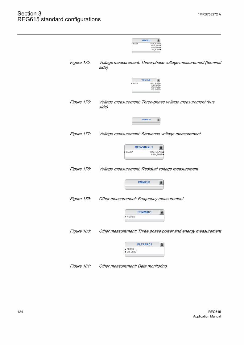
VMMXU1BLOCK HIGH_ALARM
HIGH_WARNLOW_WARN
LOW_ALARM
GUID-3238D828-753A-43E8-99D8-234B9EA3DC59 V2 EN
Figure 175: Voltage measurement: Three-phase voltage measurement (terminalside)
VMMXU2BLOCK HIGH_ALARM
HIGH_WARNLOW_WARN
LOW_ALARM
GUID-7DED808E-615A-4D3D-A49F-32D48A861775 V2 EN
Figure 176: Voltage measurement: Three-phase voltage measurement (busside)
VSMSQI1
GUID-A8DE0078-324F-419E-92F5-2111E649C995 V2 EN
Figure 177: Voltage measurement: Sequence voltage measurement
RESVMMXU1BLOCK HIGH_ALARM
HIGH_WARN
GUID-836F9B73-114A-42E9-BB79-31E1AE3D4B5E V2 EN
Figure 178: Voltage measurement: Residual voltage measurement
FMMXU1
GUID-E8178B30-07FE-4760-A398-A1CE79D505CB V2 EN
Figure 179: Other measurement: Frequency measurement
PEMMXU1RSTACM
GUID-50CFD235-4E7E-4660-9DBF-8CF5AC0C71C6 V2 EN
Figure 180: Other measurement: Three phase power and energy measurement
FLTRFRC1BLOCKCB_CLRD
GUID-A484E2BE-C2AA-416F-83FA-23D1DBA7F930 V2 EN
Figure 181: Other measurement: Data monitoring
Section 3 1MRS758272 AREG615 standard configurations
124 REG615Application Manual

LDPRLRC1RSTMEM MEM_WARN
MEM_ALARM
GUID-5A6A437F-A412-44BC-B25C-1A053B886CD4 V2 EN
Figure 182: Other measurement: Load profile record
3.5.3.6 Functional diagrams for IOs and alarm LEDs
ORB1B2
O
ORB1B2
O
ORB1B2
O
ORB1B2
O
ORB1B2
O
ORB1B2
O
ORB1B2
O
ORB1B2
O X110_BI8_CB_OPENED
X110_BI7_CB_CLOSED
X110_BI4_CB_TRUCK_IN_TEST
X110_BI3_CB_TRUCK_IN_SERVICE
X110_BI6_ES1_OPENED
X110_BI5_ES1_CLOSED
X110_BI1_TERMINAL_VT_MCB_OPEN
X110_BI2_BUSBARL_VT_MCB_OPENX110 (BIO)_110.X110-Input 2
X110 (BIO-H)_110.X110-Input 4
X110 (BIO-H)_110.X110-Input 7
X110 (BIO-H)_110.X110-Input 1
X110 (BIO)_110.X110-Input 7
X110 (BIO)_110.X110-Input 3
X110 (BIO)_110.X110-Input 4
X110 (BIO)_110.X110-Input 5
X110 (BIO-H)_110.X110-Input 5
X110 (BIO)_110.X110-Input 1
X110 (BIO)_110.X110-Input 8
X110 (BIO-H)_110.X110-Input 6
X110 (BIO-H)_110.X110-Input 2
X110 (BIO-H)_110.X110-Input 3
X110 (BIO)_110.X110-Input 6
X110 (BIO-H)_110.X110-Input 8GUID-AC5DC181-7A2E-4B16-9889-5C0798EE5932 V2 EN
Figure 183: Default binary input - X110
1MRS758272 A Section 3REG615 standard configurations
REG615 125Application Manual

X130_BI3_RST_LOCKOUT
X130_BI1_EXT_TRIP1
X130_BI2_EXT_TRIP2
X130_BI4_FIELD_EXCITATION_OPEN
X130 (AIM)_130.X130-Input 1
X130 (AIM)_130.X130-Input 2
X130 (AIM)_130.X130-Input 3
X130 (AIM)_130.X130-Input 4GUID-7C2F8CE9-9CD5-4118-B708-CFEE42A9BE73 V2 EN
Figure 184: Default binary input - X130
CB_OPEN_COMMAND
GENERAL_OPERATE_PULSE
PRIMEMOVER_SHUTDOWN_PULSE
TRPPTRC6_TRIP_FIELD_EXCITATION
TRPPTRC2_TRIP
CCBRBRF1_TRBU
X100 (PSM)_100.X100-PO1
X100 (PSM)_100.X100-PO2
X100 (PSM)_100.X100-PO3
X100 (PSM)_100.X100-PO4
X100 (PSM)_100.X100-SO1
X100 (PSM)_100.X100-SO2
GUID-7F284A09-86F3-43F3-B3EF-FCCCED254285 V2 EN
Figure 185: Default binary output - X100
Section 3 1MRS758272 AREG615 standard configurations
126 REG615Application Manual

TRPPTRC3_TRIP
TRPPTRC4_TRIP
TRPPTRC5_TRIP
FREQUENCY_OPERATE_PULSE
THERMAL_AND_NEQSEQ_OPERATE_PULSE
SECRSYN1_SYNC_OK
MPDIF_OPERATE_PULSE
X110 (BIO-H)_110.X110-HSO1
X110 (BIO-H)_110.X110-HSO2
X110 (BIO-H)_110.X110-HSO3
X110 (BIO)_110.X110-SO1
X110 (BIO)_110.X110-SO2
X110 (BIO)_110.X110-SO3
X110 (BIO)_110.X110-SO4GUID-1D844883-78D6-4C59-99AF-79C2783786E5 V2 EN
Figure 186: Default binary output - X110
1MRS758272 A Section 3REG615 standard configurations
REG615 127Application Manual

LED1OKALARMRESET
LED2OKALARMRESET
LED3OKALARMRESET
LED4OKALARMRESET
LED5OKALARMRESET
OR6B1B2B3B4B5B6
O
ORB1B2
O
ANDB1B2
O
ORB1B2
O
SECRSYN1_SYNC_OKX110_BI8_CB_OPENED
PHPVOC1_OPERATE
MPDIF1_OPERATE
EF_OPERATEROVPTOV_OPERATE
DOPPDPR_OPERATEDUPPDPR_OPERATE
PHxPTOC_OPERATE
GUID-C39D654F-2BBA-4055-8365-F06F62B59464 V2 EN
Section 3 1MRS758272 AREG615 standard configurations
128 REG615Application Manual

LED6OKALARMRESET
LED7OKALARMRESET
LED8OKALARMRESET
LED9OKALARMRESET
LED10OKALARMRESET
LED11OKALARMRESET
OR6B1B2B3B4B5B6
O
ORB1B2
O
CCBRBRF1_TRBU
T2PTTR1_OPERATE
SEQSPVC1_FUSEF_U
MNSPTOC_OPERATE
FREQUENCY_OPERATE
TCSSCBR_ALARMSSCBR1_ALARMS
DISTURB_RECORD_TRIGGERED
ARC_OPERATE
MDSOPT1_ALARM
GUID-65343909-373B-4FF9-BEB9-FBCE9230B778 V2 EN
Figure 187: Default LED connection
3.5.3.7 Functional diagram for other timer logics
The configuration includes differential operate, frequency operate, thermal andnegative-sequence protection operate, prime mover shutdown logic, blocking logicfor frequency protection and logic to disable directional underpower protection. Theoperate logics are connected to the minimum pulse timer TPGAPC for setting theminimum pulse length for the outputs. The output from TPGAPC is connected to thebinary outputs.
TPGAPC2IN1IN2
OUT1OUT2
MPDIF_OPERATE_PULSEMPDIF1_OPERATE
GUID-3633C947-5882-43BA-9599-E46957D804D2 V2 EN
Figure 188: Timer logic for differential protection operate pulse
1MRS758272 A Section 3REG615 standard configurations
REG615 129Application Manual

TPGAPC3IN1IN2
OUT1OUT2
ORB1B2
O
FREQUENCY_OPERATE_PULSETHERMAL_AND_NEQSEQ_OPERATE_PULSE
T2PTTR1_OPERATE
FREQUENCY_OPERATE
MNSPTOC_OPERATE
GUID-F0E04110-E8C3-4CC6-A315-04B624B990DE V2 EN
Figure 189: Timer logic for voltage/frequency and thermal/negative sequence protection operate pulse
OR6B1B2B3B4B5B6
O
OR6B1B2B3B4B5B6
O
TPGAPC4IN1IN2
OUT1OUT2
OR6B1B2B3B4B5B6
O PRIMEMOVER_SHUTDOWN_PULSE
CCBRBRF1_TRBU
PHHPTOC1_OPERATEPHIPTOC1_OPERATE
PHPVOC1_OPERATEDEFLPDEF2_OPERATEDEFLPDEF1_OPERATEDEFHPDEF1_OPERATE
EFHPTOC1_OPERATE
ROVPTOV2_OPERATE
DUPPDPR1_OPERATEDUPPDPR2_OPERATE
MPDIF1_OPERATE
ARCSARC1_OPERATEARCSARC2_OPERATEARCSARC3_OPERATE
GUID-C081E9C7-6B7C-470B-A4A4-2C81EE478D0F V2 EN
Figure 190: Timer logic for primemover shutdown pulse
ANDB1B2
OX110_BI8_CB_OPENEDX110_BI3_CB_TRUCK_IN_SERVICE
BLOCK_FREQ
GUID-062E61C6-6435-4749-AAFF-77317ED73F6B V2 EN
Figure 191: Blocking logic for frequency protection
NOTIN OUTX110_BI7_CB_CLOSED CB_NOT_CLOSED
GUID-4A0ECCDC-1551-4C96-8BD2-8A7CCE67D606 V2 EN
Figure 192: Disable logic for directional underpower protection
3.5.3.8 Other functions
The configuration includes two instances of three-phase directional overcurrentprotection, two instances of three-phase undervoltage and overvoltage protection, twoinstances of negative-sequence overvoltage and positive-sequence undervoltageprotection, 18 instances of multipurpose protection MAPGAPC, power qualityfunction and different types of timers and control functions. These functions are not
Section 3 1MRS758272 AREG615 standard configurations
130 REG615Application Manual

included in the application configuration but they can be added based on the systemrequirements.
1MRS758272 A Section 3REG615 standard configurations
REG615 131Application Manual

132

Section 4 Requirements for measurementtransformers
4.1 Current transformers
4.1.1 Current transformer requirements for non-directionalovercurrent protection
For reliable and correct operation of the overcurrent protection, the CT has to bechosen carefully. The distortion of the secondary current of a saturated CT mayendanger the operation, selectivity, and co-ordination of protection. However, whenthe CT is correctly selected, a fast and reliable short circuit protection can be enabled.
The selection of a CT depends not only on the CT specifications but also on thenetwork fault current magnitude, desired protection objectives, and the actual CTburden. The protection settings of the protection relay should be defined in accordancewith the CT performance as well as other factors.
4.1.1.1 Current transformer accuracy class and accuracy limit factor
The rated accuracy limit factor (Fn) is the ratio of the rated accuracy limit primarycurrent to the rated primary current. For example, a protective current transformer oftype 5P10 has the accuracy class 5P and the accuracy limit factor 10. For protectivecurrent transformers, the accuracy class is designed by the highest permissiblepercentage composite error at the rated accuracy limit primary current prescribed forthe accuracy class concerned, followed by the letter "P" (meaning protection).
Table 26: Limits of errors according to IEC 60044-1 for protective current transformers
Accuracy class Current error atrated primarycurrent (%)
Phase displacement at rated primarycurrent
Composite error atrated accuracy limitprimary current (%)minutes centiradians
5P ±1 ±60 ±1.8 5
10P ±3 - - 10
The accuracy classes 5P and 10P are both suitable for non-directional overcurrentprotection. The 5P class provides a better accuracy. This should be noted also if thereare accuracy requirements for the metering functions (current metering, powermetering, and so on) of the protection relay.
The CT accuracy primary limit current describes the highest fault current magnitudeat which the CT fulfils the specified accuracy. Beyond this level, the secondary current
1MRS758272 A Section 4Requirements for measurement transformers
REG615 133Application Manual

of the CT is distorted and it might have severe effects on the performance of theprotection relay.
In practise, the actual accuracy limit factor (Fa) differs from the rated accuracy limitfactor (Fn) and is proportional to the ratio of the rated CT burden and the actual CTburden.
The actual accuracy limit factor is calculated using the formula:
F FS S
S Sa n
in n
in
≈ ×
+
+
A071141 V1 EN
Fn the accuracy limit factor with the nominal external burden Sn
Sin the internal secondary burden of the CT
S the actual external burden
4.1.1.2 Non-directional overcurrent protection
The current transformer selectionNon-directional overcurrent protection does not set high requirements on the accuracyclass or on the actual accuracy limit factor (Fa) of the CTs. It is, however,recommended to select a CT with Fa of at least 20.
The nominal primary current I1n should be chosen in such a way that the thermal anddynamic strength of the current measuring input of the protection relay is notexceeded. This is always fulfilled when
I1n > Ikmax / 100,
Ikmax is the highest fault current.
The saturation of the CT protects the measuring circuit and the current input of theprotection relay. For that reason, in practice, even a few times smaller nominalprimary current can be used than given by the formula.
Recommended start current settingsIf Ikmin is the lowest primary current at which the highest set overcurrent stage is tooperate, the start current should be set using the formula:
Current start value < 0.7 × (Ikmin / I1n)
I1n is the nominal primary current of the CT.
The factor 0.7 takes into account the protection relay inaccuracy, current transformererrors, and imperfections of the short circuit calculations.
Section 4 1MRS758272 ARequirements for measurement transformers
134 REG615Application Manual

The adequate performance of the CT should be checked when the setting of the highset stage overcurrent protection is defined. The operate time delay caused by the CTsaturation is typically small enough when the overcurrent setting is noticeably lowerthan Fa.
When defining the setting values for the low set stages, the saturation of the CT doesnot need to be taken into account and the start current setting is simply according to theformula.
Delay in operation caused by saturation of current transformersThe saturation of CT may cause a delayed protection relay operation. To ensure thetime selectivity, the delay must be taken into account when setting the operate timesof successive protection relays.
With definite time mode of operation, the saturation of CT may cause a delay that isas long as the time the constant of the DC component of the fault current, when thecurrent is only slightly higher than the starting current. This depends on the accuracylimit factor of the CT, on the remanence flux of the core of the CT, and on the operatetime setting.
With inverse time mode of operation, the delay should always be considered as beingas long as the time constant of the DC component.
With inverse time mode of operation and when the high-set stages are not used, the ACcomponent of the fault current should not saturate the CT less than 20 times thestarting current. Otherwise, the inverse operation time can be further prolonged.Therefore, the accuracy limit factor Fa should be chosen using the formula:
Fa > 20 × Current start value / I1n
The Current start value is the primary start current setting of the protection relay.
4.1.1.3 Example for non-directional overcurrent protection
The following figure describes a typical medium voltage feeder. The protection isimplemented as three-stage definite time non-directional overcurrent protection.
1MRS758272 A Section 4Requirements for measurement transformers
REG615 135Application Manual

A071142 V1 EN
Figure 193: Example of three-stage overcurrent protection
The maximum three-phase fault current is 41.7 kA and the minimum three-phase shortcircuit current is 22.8 kA. The actual accuracy limit factor of the CT is calculated tobe 59.
The start current setting for low-set stage (3I>) is selected to be about twice thenominal current of the cable. The operate time is selected so that it is selective with thenext protection relay (not visible in Figure 193). The settings for the high-set stage andinstantaneous stage are defined also so that grading is ensured with the downstreamprotection. In addition, the start current settings have to be defined so that theprotection relay operates with the minimum fault current and it does not operate withthe maximum load current. The settings for all three stages are as in Figure 193.
For the application point of view, the suitable setting for instantaneous stage (I>>>) inthis example is 3 500 A (5.83 × I2n). For the CT characteristics point of view, thecriteria given by the current transformer selection formula is fulfilled and also theprotection relay setting is considerably below the Fa. In this application, the CT ratedburden could have been selected much lower than 10 VA for economical reasons.
Section 4 1MRS758272 ARequirements for measurement transformers
136 REG615Application Manual

Section 5 IED physical connections
5.1 Inputs
5.1.1 Energizing inputs
5.1.1.1 Phase currents
Table 27: Phase current inputs included in configurations A and C
Terminal DescriptionX120:7-8 IL1
X120:9-10 IL2
X120:11-12 IL3
Table 28: Phase current inputs included in configuration D
Terminal DescriptionX120:1-2 IL1B
X120:3-4 IL2B
X120:5-6 IL3B
X120:7-8 IL1
X120:9-10 IL2
X120:11-12 IL3
5.1.1.2 Residual current
Table 29: Residual current input included in configurations A, C and D
Terminal DescriptionX120:13-14 Io
5.1.1.3 Phase voltages
Table 30: Phase voltage inputs included in configurations A, C and D
Terminal DescriptionX130:11-12 U1
X130:13-14 U2
X130:15-16 U3
1MRS758272 A Section 5IED physical connections
REG615 137Application Manual

Table 31: Reference voltage input for SECRSYN1 included in configurations A and D
Terminal DescriptionX130:9-10 U12B
5.1.1.4 Residual voltage
Table 32: Additional residual voltage input included in configurations A, C and D
Terminal DescriptionX130:9-10 UoB1)
X130:17-18 Uo
1) Used only for H3EFPSEF1 in configuration C
5.1.2 Auxiliary supply voltage input
The auxiliary voltage of the protection relay is connected to terminals X100:1-2. AtDC supply, the positive lead is connected to terminal X100:1. The permitted auxiliaryvoltage range (AC/DC or DC) is marked on the top of the LHMI of the protectionrelay.
Table 33: Auxiliary voltage supply
Terminal DescriptionX100:1 + Input
X100:2 - Input
5.1.3 Binary inputs
The binary inputs can be used, for example, to generate a blocking signal, to unlatchoutput contacts, to trigger the disturbance recorder or for remote control of IEDsettings.
Binary inputs of slot X110 are available with configurations A, C and D.
Table 34: Binary input terminals X110:1-13 with BIO0005 module
Terminal DescriptionX110:1 BI1, +
X110:2 BI1, -
X110:3 BI2, +
X110:4 BI2, -
X110:5 BI3, +
X110:6 BI3, -
X110:6 BI4, -
X110:7 BI4, +
Table continues on next page
Section 5 1MRS758272 AIED physical connections
138 REG615Application Manual

Terminal DescriptionX110:8 BI5, +
X110:9 BI5, -
X110:9 BI6, -
X110:10 BI6, +
X110:11 BI7, +
X110:12 BI7, -
X110:12 BI8, -
X110:13 BI8, +
Table 35: Binary input terminals X110:1-10 with BIO0007 module
Terminal DescriptionX110:1 BI1, +
X110:5 BI1, -
X110:2 BI2, +
X110:5 BI2, -
X110:3 BI3, +
X110:5 BI3, -
X110:4 BI4, +
X110:5 BI4, -
X110:6 BI5, +
X110:10 BI5, -
X110:7 BI6, +
X110:10 BI6, -
X110:8 BI7, +
X110:10 BI7, -
X110:9 BI8, +
X110:10 BI8, -
Binary inputs of slot X120 are available with configurations A and C.
Table 36: Binary input terminals X120-1...6
Terminal DescriptionX120:1 BI1, +
X120:2 BI1, -
X120:3 BI2, +
X120:2 BI2, -
X120:4 BI3, +
X120:2 BI3, -
X120:5 BI4, +
X120:6 BI4, -
1MRS758272 A Section 5IED physical connections
REG615 139Application Manual

Table 37:
Terminal DescriptionX130:1 BI1, +
X130:2 BI1, -
X130:2 BI2, -
X130:3 BI2, +
X130:4 BI3, +
X130:5 BI3, -
X130:5 BI4, -
X130:6 BI4, +
X130:7 BI5, +
X130:8 BI5, -
X130:8 BI6, -
X130:9 BI6, +
5.1.4 Optional light sensor inputs
If the IED is provided with the optional communication module with light sensorinputs, the pre-manufactured lens-sensor fibers are connected to inputs X13, X14 andX15. See the connection diagrams.For further information, see arc protection.
The IED is provided with connection sockets X13, X14 and X15 onlyif the optional communication module with light sensor inputs hasbeen installed. If the arc protection option is selected when ordering anIED, the light sensor inputs are included in the communicationmodule.
Table 38: Light sensor input connectors
Terminal DescriptionX13 Input Light sensor 1
X14 Input Light sensor 2
X15 Input Light sensor 3
5.2 Outputs
5.2.1 Outputs for tripping and controlling
Output contacts PO1, PO2, PO3 and PO4 are heavy-duty trip contacts capable ofcontrolling most circuit breakers. On delivery from the factory, the trip signals fromall the protection stages are routed to PO3 and PO4.
Section 5 1MRS758272 AIED physical connections
140 REG615Application Manual

Table 39: Output contacts
Terminal DescriptionX100:6 PO1, NO
X100:7 PO1, NO
X100:8 PO2, NO
X100:9 PO2, NO
X100:15 PO3, NO (TCS resistor)
X100:16 PO3, NO
X100:17 PO3, NO
X100:18 PO3 (TCS1 input), NO
X100:19 PO3 (TCS1 input), NO
X100:20 PO4, NO (TCS resistor)
X100:21 PO4, NO
X100:22 PO4, NO
X100:23 PO4 (TCS2 input), NO
X100:24 PO4 (TCS2 input), NO
5.2.2 Outputs for signalling
SO output contacts can be used for signalling on start and tripping of the IED. Ondelivery from the factory, the start and alarm signals from all the protection stages arerouted to signalling outputs.
Table 40: Output contacts X100:10-14
Terminal DescriptionX100:10 SO1, common
X100:11 SO1, NC
X100:12 SO1, NO
X100:13 SO2, NO
X100:14 SO2, NO
Output contacts of slot X110 are optional for configurations A, C and D.
Table 41: Output contacts X110:14-24 with BIO0005
Terminal DescriptionX110:14 SO1, common
X110:15 SO1, NO
X110:16 SO1, NC
X110:17 SO2, common
X110:18 SO2, NO
X110:19 SO2, NC
Table continues on next page
1MRS758272 A Section 5IED physical connections
REG615 141Application Manual

Terminal DescriptionX110:20 SO3, common
X110:21 SO3, NO
X110:22 SO3, NC
X110:23 SO4, common
X110:24 SO4, NO
Table 42: Optional high-speed output contacts X110:15-24 with BIO0007
Terminal DescriptionX110:15 HSO1, NO
X110:16 HSO1, NO
X110:19 HSO2, NO
X110:20 HSO2, NO
X110:23 HSO3, NO
X110:24 HSO3, NO
Table 43: Output contacts X130:10-18
Terminal DescriptionX130:10 SO1, common
X130:11 SO1, NO
X130:12 SO1, NC
X130:13 SO2, common
X130:14 SO2, NO
X130:15 SO2, NC
X130:16 SO3, common
X130:17 SO3, NO
X130:18 SO3, NC
5.2.3 IRF
The IRF contact functions as an output contact for the self-supervision system of theprotection relay. Under normal operating conditions, the protection relay is energizedand the contact is closed (X100:3-5). When a fault is detected by the self-supervisionsystem or the auxiliary voltage is disconnected, the output contact drops off and thecontact closes (X100:3-4).
Table 44: IRF contact
Terminal DescriptionX100:3 IRF, common
X100:4 Closed; IRF, or Uaux disconnected
X100:5 Closed; no IRF, and Uaux connected
Section 5 1MRS758272 AIED physical connections
142 REG615Application Manual

Section 6 Glossary
615 series Series of numerical protection and control relays forprotection and supervision applications of utilitysubstations, and industrial switchgear and equipment
AC Alternating currentAI Analog inputASCII American Standard Code for Information InterchangeBI Binary inputBIO Binary input and outputBO Binary outputCT Current transformerDAN Doubly attached nodeDC 1. Direct current
2. Disconnector3. Double command
DNP3 A distributed network protocol originally developed byWestronic. The DNP3 Users Group has the ownershipof the protocol and assumes responsibility for itsevolution.
DPC Double-point controlEMC Electromagnetic compatibilityEthernet A standard for connecting a family of frame-based
computer networking technologies into a LANFIFO First in, first outFTP File transfer protocolFTPS FTP SecureGOOSE Generic Object-Oriented Substation EventHMI Human-machine interfaceHSO High-speed outputHSR High-availability seamless redundancyHTTPS Hypertext Transfer Protocol SecureI/O Input/outputIEC International Electrotechnical Commission
1MRS758272 A Section 6Glossary
REG615 143Application Manual

IEC 60870-5-103 1. Communication standard for protective equipment2. A serial master/slave protocol for point-to-pointcommunication
IEC 61850 International standard for substation communicationand modeling
IEC 61850-8-1 A communication protocol based on the IEC 61850standard series
IEC 61850-9-2 A communication protocol based on the IEC 61850standard series
IEC 61850-9-2 LE Lite Edition of IEC 61850-9-2 offering process businterface
IED Intelligent electronic device (protection and controlrelay)
IEEE 1588 v2 Standard for a Precision Clock SynchronizationProtocol for networked measurement and controlsystems
IEEE 1686 Standard for Substation Intelligent Electronic Devices'(IEDs') Cyber Security Capabilities
IP address A set of four numbers between 0 and 255, separated byperiods. Each server connected to the Internet isassigned a unique IP address that specifies the locationfor the TCP/IP protocol.
IRIG-B Inter-Range Instrumentation Group's time code formatB
LAN Local area networkLCD Liquid crystal displayLE Light EditionLED Light-emitting diodeLHMI Local human-machine interfaceMAC Media access controlMCB Miniature circuit breakerMMS 1. Manufacturing message specification
2. Metering management systemModbus A serial communication protocol developed by the
Modicon company in 1979. Originally used forcommunication in PLCs and RTU devices.
Modbus TCP/IP Modbus RTU protocol which uses TCP/IP and Ethernetto carry data between devices
NC Normally closed
Section 6 1MRS758272 AGlossary
144 REG615Application Manual

NO Normally openPCM600 Protection and Control IED ManagerPO Power outputPRP Parallel redundancy protocolPTP Precision Time ProtocolRIO600 Remote I/O unitRJ-45 Galvanic connector typeRSTP Rapid spanning tree protocolRTD Resistance temperature detectorRTU Remote terminal unitSAN Single attached nodeSLD Single-line diagramSMV Sampled measured valuesSNTP Simple Network Time ProtocolSO Signal outputSingle-line diagram Simplified notation for representing a three-phase
power system. Instead of representing each of threephases with a separate line or terminal, only oneconductor is represented.
TCS Trip-circuit supervisionVT Voltage transformerWAN Wide area networkWHMI Web human-machine interface
1MRS758272 A Section 6Glossary
REG615 145Application Manual

146

147

Contact us
ABB OyMedium Voltage Products,Distribution AutomationP.O. Box 699FI-65101 VAASA, FinlandPhone +358 10 22 11Fax +358 10 22 41094
www.abb.com/mediumvoltage
www.abb.com/substationautomation
ABB India Limited,Distribution AutomationManeja WorksVadodara-390013, IndiaPhone +91 265 6724402Fax +91 265 6724423
www.abb.com/mediumvoltage
www.abb.com/substationautomation
1MR
S75
8272
A©
Cop
yrig
ht 2
016
AB
B. A
ll rig
hts
rese
rved
.