Generalized Impedances and Wakes in Asymmetric Structures1 · Generalized Impedances and Wakes in...
17
SLAC/APllO January 1998 Generalized Impedances and Wakes in Asymmetric Structures1 S. Heifets, A. Wagner*, B. Zotter” Stanford Linear Accelerator Center, Stanford University, Stanford, CA 94309, USA lSupported by Department of Energy contract DE-AC03%76SF00515. * Visitor from CERN/SL-AP, CH-1211 Geneva 23 --
Transcript of Generalized Impedances and Wakes in Asymmetric Structures1 · Generalized Impedances and Wakes in...

SLAC/APllO January 1998
Generalized Impedances and Wakes in Asymmetric Structures1
S. Heifets, A. Wagner*, B. Zotter”
Stanford Linear Accelerator Center, Stanford University, Stanford, CA
94309, USA
lSupported by Department of Energy contract DE-AC03%76SF00515. * Visitor from CERN/SL-AP, CH-1211 Geneva 23
--

1 Introduction
In most applications to particle accelerators, impedances and wake functions are defined for test and exciting charges traveling on the same trajectory, parallel to the axis of the structure. It is assumed that the velocity of the charges is ultra-relativistic (U = c), and both the velocity and the trajec- tory remain unchanged by the EM fields excited by the charged particles themselves. This definition is quite satisfactory for beams in rotationally symmetric structures, such as rf cavities with circular cross section. In such geometries, the electro-magnetic (EM) fields can be expanded into azimuthal harmonics proportional to cos(m~$) or sin(m4). The strongest longitudinal impedance is produced by the uniform harmonic (m = 0), and is indepen- dent of the offsets of both charges. The strongest transverse impedance is generated by the dipole harmonic (m = l), and is proportional to the offset of the exciting charge, but does not depend on the offset of the test charge. For particle beams near the axis, higher harmonics can usually be neglected. The same considerations hold for the wake functions.
Some elements used in particle accelerators are not rotationally symmet- _. ric, although they still have a well defined axis. Examples are vacuum cham- bers with elliptic or rectangular cross sections, and symmetrically disposed plates on two or four sides of a beam, used e.g. for pickups or separators. In such structures the impedances become dependent also on the offset of the test charge. In this case it is necessary to define generalized impedances, which take into account arbitrary offsets of the trajectories of both the excit- ing and the test charge from the axis. In structures with even less symmetry, such as pumping slots not distributed uniformly around the vacuum cham- ber, or one-sided collimators and cavities, it is even not always possible to uniquely define an axis. However, impedances and wake functions can still be obtained by integrating the EM fields along straight lines parallel to the beam trajectory, for various transverse positions of the test and exciting charge. Again the same considerations hold for the wake functions.
The concept of generalized impedances with different trajectories for source and field particles has been introduced already many years ago for the purpose of measuring impedances[l]. A similar generalization can be made for wake functions or wake potentials in the time domain. Due to the more complex geometry of axially non-symmetric structures, the EM fields can be calculated analytically only in very few of them. Expressions in closed form are known for the impedance of elliptic beam pipes with fi-
2

-
nite wall resistivity[2]. For the same case, the wake potentials of Gaussian bunches have been given in integral form[3], but the integrals can only be evaluated numerically[4]. It is also possible to express the impedance of a resistive pipes with arbitrary cross section in terms of its electrostatic capac- itance, and the impedance of a resistive pipe with rectangular cross section has been obtained in closed form in that manner[5].
From numerical results for transverse wake potentials and loss factors of Gaussian bunches in axially non-symmetric structures it was deduced that they can be separated into dipolar components, proportional only to the offset of the exciting charge, and quadrupolar components, proportional only to the offset of the test charge. Higher-order components are small near the axis and can usually be neglected. In rotationally symmetric structures, the quadrupolar component vanishes and only the dipolar term remains.
The deflection of a charged particle in a dipolar wake potential, as in the case of circular symmetric structures, is always defocusing, i.e. deflecting the beam further out from its radial position. However, in a quadrupolar wake it is defocusing in one transverse direction, but focusing in the orthogonal
-- one. This property is used e.g. in the CLIC focusing scheme with so-called rf quadrupoles. The original proposal[6] had axially non-symmetric, elongated beam-hole slots in circular cylindrical cavities, but for technical reasons the geometry was changed to circular beam holes in elliptical cavities.
The dipolar and quadrupolar wake potentials are proportional to the off- sets of the leading or the trailing charge. It is therefore sufficient to compute them for unit offset, and multiply them with the values of the actual off- sets. They can be pre-calculated and stored in three one-dimensional tables, one for each spatial dimension. This can be done for any bunch shape - in particular for a that of a basis function[7] which may be used to describe arbitrary distributions. This is very useful for the simulation of collective effects in circular accelerators or storage rings, which require knowledge of the wake potentials of bunches which are in general distorted and displaced in all directions. It would be much too slow to compute their wake po- tentials for different offsets on every turn, but they can thus be obtained very quickly from look-up tables containing the longitudinal, dipolar and quadrupolar wake potentials with unit offset for a structure, or even for all elements forming the vacuum chamber[8].
3
--

__
2 Asymmetric Vacuum Chamber Elements
Effective wake potentials, in similarity to efective impedances can be defined as integrals over the product of wake potentials and the distribution function, hence they are the same as the loss or kick factors. In the transverse direc- tions, they have two components which we choose as x and y in Cartesian coordinates. In not-axially symmetric structures, they are in general func- tions of the positions of both the exciting bunch and of the test charge. In structures with enough symmetry to define an axis, e.g. with two orthogonal planes of symmetry, the offsets are measured from this axis. Near this axis, the wake potentials are essentially superpositions of dipolar fields, propor- tional to cos or sin$, and quadrupolar components, proportional to cos or sin24. Higher order components are small, as can be seen in the attached figures for two different LEP components.
Figs.1 a-d show as vector fields the x and y components of the effective transverse wake potentials (kick factors) of a Gaussian bunch with 0 = 1Omm in the shielded LEP bellows. These have an oval cross section, with two orthogonal planes of symmetry, but an asymmetrically tapered profile in the longitudinal direction. The kick factors are plotted as functions of the offsets of the test charge for 4 different beam positions: la) centered, lb) and lc) offset by 4 mm in x, respectively in y, and Id) offsets in both the z and y directions. The centered bunch excites an almost pure quadrupolar component, while the offset bunches yield more complicated field patterns.
In Figs.2 a-d, the quadrupolar component (Fig.la) has been subtracted from the total vector field. Hence the first picture, for a centered bunch, is identically zero as it is subtracted from itself. For the displaced bunches, the residual kick factors are essentially dipolar fields. The vectors are nearly constant in length, and parallel to the displacement of the exciting bunch, i.e. they are independent of the position of the test beam. They are further- more proportional to the distance of the exciting beam from the axis. As can be seen, there is only little distortion of these dipolar fields due to the admixture of higher-order components. They can usually be neglected in the neighborhood of the axis, where the beams are generally located in particle accelerators and storage rings, in order to minimize particle losses.
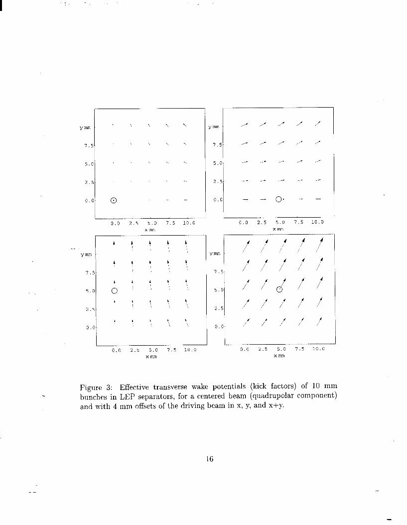
Figs. 3 and 4 show the same plots of kick factors for the LEP separators. These consist of two parallel plates, disposed symmetrically above and below the axis of a widened circular vacuum chamber with longitudinally symmet- ric, tapered side walls. The offsets here are slightly larger (50 mm), but the
4
--

separation into dipolar and quadrupolar components is still quite accurate. The dipolar components are in general proportional to the distance of the exciting beam from the axis, and independent of the test beam offset.
In rotationally symmetric structures, it is well known that the transverse wake vanishes completely for centered beams, hence the quadrupolar com- ponent is zero. The wakes have only dipolar components, plus some weaker higher-order terms which can usually be neglected near the axis.
In previous computations of transverse kicks due to wake potentials, only dipolar components have been taken into account. While this is admissible for the wakes due to rotationally symmetric structures, it can lead to incorrect results in structures which lack that symmetry. Then it is important to include the quadrupolar components which are often of the same order of magnitude as the dipolar terms.
Here we present an analytic approach to the calculation of the depen- dence of wake potentials on offsets in structures with and without rotational symmetry. The resulting expressions permit estimates of the importance of the higher-order field components which are often neglected without justi-
--fication. They also permit quick verification of numerical results which are difficult and/or time consuming to obtain. In particular, the computation
of wake potentials of short bunches in large structures without axial symme- try is often limited by memory space, or requires excessive computing times, even with the fastest computers presently available.
3 Cylindrical Symmetric Structures
First we recapitulate the dependence of impedances on offsets (ra, &) of an ultra-relativistic particle beam (U = c) in a cylindrically symmetric structure, and on the coordinates (r, 4) of the trailing particle, where the integration over the fields is performed:
The impedance must satisfy the causality condition:
(2)
--

-
3.1 Synchronous Field Component
The effects of EM fields traveling at speeds different from the beam velocity, 21 = PC, average to zero. Hence the impedance is given entirely by the synchronous component of the EM field[9]. In frequency domain these fields are proportional to eikz. We will split the total field E,(w) into a synchronous
component E,“y” and the rest I,
Ez(w, r, 4, z, To, $0) = $Zyn(r, 4, To, hJeikz + f,(w, r, 4, To, 40) , (3)
where E, is assumed to be orthogonal to eikz when the range of integration L -+ 00, and thus is not synchronous with the beam. The impedance is then given by
21, CJJ, To, r, 40,4> = E,“yn(r, To, 4,40> . (4)
The dependence of E, ‘yn on r can be found from the fact that both terms in Eq. (3) have different dependences on Z, and therefore they have to satisfy the wave equation independently. For the synchronous component, the wave
__ -equation is reduced to the Laplace equation:
&Eiyn(r, 4, To, 40) = 0 (5)
for r # ro. Hence, the non-singular solution is given by
21, (w, r, 4, To, 40) o( EiYn (r, 4, To, $0) 0~ rmeim@ . (6)
3.2 Taylor Expansion
The impedance can be expanded into a power series in the offset of the trailing particles, normalized to a typical transverse dimension of the vacuum chamber. Because the eigen-functions are not singular, the expansion starts in general with a constant term:
Q4 r, 4, TO, $0) = C Cm(rO, $0)rmeim4 + cc , m>O
(7)
where cc stands for the complex conjugate. Also the coefficients Cm(ro, $o) can be expanded into a Taylor series to get the double series:
zli (w, r, 4, r-0, $0) = c c Cmkr~rmei(m’-k’o) + cc . m>O k>O
(8)
6

-.
Since the EM fields in an axisymmetric structure depend only on the differ- ence 4 - $o, also the impedance must have that dependence. Therefore all coefficients with k # m vanish, and one obtains the single series:
Z,,(w, r, 4, ro, $o) = C Cmmr~rmeim(+90) + cc . m>O -
(9)
For small offsets, the main contribution is given by the lowest order terms in the expansion. The dominant longitudinal impedance is given by the m = 0 term Coo, which is independent of all offsets.
The transverse (radial) impedance is obtained by taking the derivative w.r.t. the field coordinate T. Hence
ZI(w, r, c$,rg, $0) = C Cmmmrm-1r~eim(4-40) + cc . (10) m>l -
The lowest non-vanishing term is for m = 1, i.e. the dipolar component, and the dominant transverse impedance is:
ZL(w, r, $,7-o, $o)(“=‘) = C11r0ei(4-40) + cc . (11)
It can be seen that the dipole impedance is independent of the radial dis- placement r of the trailing particle, but proportional to that of the leading one ro. However, unless the two particle are in the same azimuthal plane, it also depends on the difference of the azimuthal angles ($ - $0).
3.2.1 Longitudinal Symmetry
Additional constraints exist if the structure has certain symmetries. For structures longitudinally symmetric w.r.t the (x, y) plane, i.e. which
remain unchanged for z -+ -x, the impedance must be the same when the offsets of the leading and trailing particles are interchanged:
21, h r, A ~0, $0) = zll (-4 r0,40, r, 4) . (12)
This relation is actually an expression of time reversibility for symmetric structures. In general, time reversibility relates impedances of two structures which are mirror reflected w.r.t. the (x, y) plane. This property was used before to prove the independence of impedances on the direction of particle motion through a structure which is not longitudinally symmetric.
A consequence of this symmetry is that the expansion coefficients must fulfill the relation C,,( -w) = C;,(w).
7
--

.
4 Rotationally Non-symmetric Structures
The electric field strength can be written as a double Fourier transform
7, To) + A*(-W, -q, 7, F,,)]ei(qr“‘t)
where we write r’= (z, y) and r: = (Q,, ~a) for short.
4.1 Impedance
The synchronous component with q = k = w/c is then
E;““(F, Foe, t) = [A(w, k, r’, 70) + A*(-W, -k, f’,~‘~)]e~(~~-“‘~) ,
and defines the longitudinal impedance:
Z,,(w, r’, To) = A(w, k, 7, ~7,) + A*(+, 4, r’, ~5,) .
The causality condition
7 (13)
(14
(15)
(16)
is then fulfilled automatically. The synchronous field component has to fulfill the wave equation (A + k2) Eiy” = 0, hence A,Z,,(w, 7, FO) = 0. Since the
impedance must be a solution of the Laplace equation, it can be written in terms of powers or the complex variables T* = x zk iy:
qw, r’, To) = 5 [Cm@, ~o)r_c” + Dm(W, ~o)rrn] , (17) m=O
From Eq.(16) follows the symmetry
Dm(W) = CA(-w) . (18)
One can further express the coefficients Cm as a power series in Foe, and gets the impedance as a double infinite sum:
zjj(W,r’,r’o) = 5 g { [Qm/c(W)ri+ + Pmk(W)$-]T;1+ m=l k=O
[4&+;- + g&J)r$]rrn} , (19)
where TO* = z. 3~ iyo. Contrary to the axi-symmetric case, this double sum, cannot be reduced to a single one.
For easier understanding, we now switch to the time domain.
8
--

4.2 Wake Function
We introduce the Fourier transforms of the coefficients
am/c(S) = s 00 dw -cxm~(w)e-iws~c ,
-cc 27r
Hence the longitudinal wake function can be written
W,,(S) = 2 2 [arnk(S)$+ + Pmk(S)rk-]r~ + m=O /c=O
Similarly, the transverse wake function components become
Wz(S) = 2 F m( [&k(S)rt+ + bmk(S)r~-]r~-l +
m=O k=O _-
[&,(s,r,“- + b;k(S)l.gk+]P} 1 (22)
where aarnk (s)/~‘s = - am/c(s) and abrnk(s)/ds = -@ml,(s).
From Maxwell’s equations and the definition of the wake functions, one can derive the general relations
aw, aw, aw, aw, -=-- -= - dX dY ’ dY 3X
(23)
It can be verified that these equations are fulfilled by the above expressions.
4.2.1 Lowest Order Terms
Ordering the terms of equal powers in x, y and x0, yo, one finds that the coefficients appear always in the combinations Re or Im (o’,k f Pmk). We put 2 Re (o,k + pm,) = Cmk and 2 Im (CY,I, + ,Bmk) = D,I,. The difference terms are distinguished by a bar over the letter: Cmk= 2 Re (omk - prnlc) and
Dmk= 2 Im (am/c - Pmk).
9
--

-
Similar relations hold for the coefficients urnk and b,k, and we designate their combinations with small letters cmk = 2 Re arnk + bmk, d,k 2 Im umk + b mkr and the barred coefficients when the plus is replaced by a minus sign. The components of the wake functions can then be written:
W,,(s) = ~00+(~0~0~+~~~0)-(~0~0~+~~~0)+(~~-y,2)~02-~~0y0~02 +
+ xo(xC~~-~~~~)-~o(x~~~+yC’~1)-t(2~-y~)Czo-22yDzo ,
K(s) = clo + xocll + 2~~20 - YO&I - @z/&o ,
WY(s) = -dlo - xodll - 2xdm - yocll - 2yc20 . (24)
4.3 Structures with Transverse Symmetries
Additional constraints are imposed if a structure has certain transverse sym- metries For mirror symmetry about the vertical (y,z) plane, one finds the condition
_- W,,(X,XO>Y,YO) = I/T/,(-x,-Xo,Y,Yo) * (25)
Therefore terms in W,, which are odd w.r.t. x and x0 must vanish, hence Coo = Co2 = Cl1 = C20 = DoI = Dlo = 0, with the same conditions on the coefficients cmk and d,k. The only terms left are:
W,,(s) = coo-YoDol-YDlo+(x~ - Yo2)Co2+(xo~CrYoYGl)+(~2 - Y2)C20 ,
K(s) = XOCll + 2=20 ,
WY(s) = -dlo - yocll - 2yczo . (26)
Hence W, is independent of vertical offsets y and yo, while W, is independent of the horizontal ones. W, furthermore vanishes when both horizontal offsets x and ~0 are zero.
For mirror symmetry about the horizontal (x,z) plane one obtains the condition W,, (x, x0, y, ya) = W,, (x, x0, -y, -yo) and hence quite analogously: similar expressions
W,,(s) = coo+xocol+xGo+( x; - Y~)Co2+xoxcll - YoYcll+(x2 - Y2)C20 ,
K(s) = Cl0 + XOCll + 2=20 ,
WY(S) = -Yoh - 2YC20 * (27)
10
--
For structures with symmetry about both the horizontal (yz) and the vertical (xz) planes, the same equations hold but without the constant terms:
W,,(s) = coo + (xi - Yfwo2 + (xoxc11 - YOYG) + (x2 - Y2)C20 ,
W&) = XOCll + 2=20 ,
WY(S) = -YoC11 - aG?o . (28)
For symmetry w.r.t. rotation by 90” - which includes the case of symmetry about two orthogonal planes as well as that of circular symmetry - one finds
W(s) = xo Re (h) W,(s) = YO Re (h) . (29)
In this case, the quadrupolar component of the field does not give a contri- bution, and the transverse wakes depend only on the offset of the leading particle in the corresponding plane.
For symmetry about the horizontal (XZ) plane, the next order (sextupo- -_lar) terms are
J%(s) = -~XOYO&~ + 2(xoyd,l + yoxd21) + 6~~230 ,
WY(s) = -2xoyoG2 - 2(xoyc21 + yoxdzl) - 6xyd30 . (30)
They change sign with x, x0, but also with y, yo, hence they are equally valid for symmetry about the vertical (yz) plane. However, when a structure is symmetric w.r.t. both planes, W, should be odd in x but even in y, and the opposite for W,. Hence in that case all sextupolar terms are zero, and
octupolar terms are the lowest non-vanishing corrections:
Wz(s) = -x0(x; - 3y,2) Cl3 - 3x0(x2 - Y”) ~31 + 6xyyod31 >
WY(s) = yo(x; - y,“) 213 + 3yo(x2 - y”) c31-t 6x0~~~31 . (31)
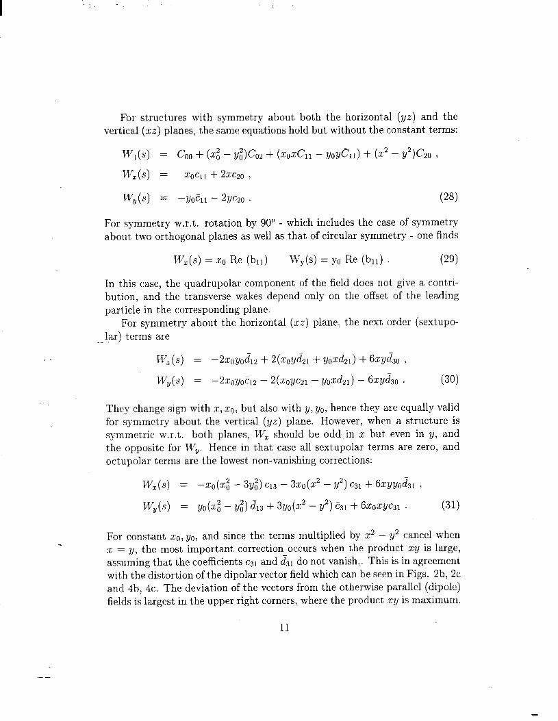
For constant x0, yo, and since the terms multiplied by x2 - y2 cancel when x = y, the most important correction occurs when the product xy is large, assuming that the coefficients csi and d -31 do not vanish,. This is in agreement
with the distortion of the dipolar vector field which can be seen in Figs. 2b, 2c and 4b, 4c. The deviation of the vectors from the otherwise parallel (dipole) fields is largest in the upper right corners, where the product xy is maximum.
11
--

.
4.4 Structures with Longitudinal Symmetry
If the structure has longitudinal symmetry about the (xy) plane, the impedance must remain the same when source and field points are interchanged. Also the direction of particle motion should be inverted, but that is known to leave the impedance unchanged even in asymmetric structures[lO]. Thus
This relation is fulfilled if okm(W) = (Ymk (w), ,&m(w) = ,6$-(-W)) and simi-
larly akm(S) = amk(S), bkm(S) = &k(S).
we therefore get the a,dditional relations cmk = ckm, crnk = i?km, and d,k = dkm. To lowest order, we find the symmetry:
aw, aw, -=- 8Yo ax0 ’
__ but, contrary to Eq. (25), this useful relation is not generally valid.
(33)
5 Conclusions
In rotationally structures, the dominant m = 0 longitudinal impedance does not depend on the offsets of either the leading or the trailing particles, while the dominant m = 1 transverse impedance is proportional to the offset of the leading particles, while it is still independent of the offsets of the trailing ones. This behavior is no longer true in rotationally non-symmetric structures, where in general all impedances depend on the offsets of both the leading and
the trailing particles. The same behavior is shown by wake functions and wake potentials. The concept of generalized impedances or generalized wake
functions must be used to calculate the effect of leading particles on trailing ones with different offsets, each described by two transverse coordinates.
This dependence of wake potentials on four additional parameters (two for each offset) would make their use very cumbersome. Fortunately it was found that the transverse wake potentials can be separated into superposi- tions of dipolar components, which are proportional to the offset of the leading bunch, and quadrupolar components, which are proportional to the offset of the trailing particles. Higher multipole components are much smaller, and can be neglected for most structures without rotational symmetry.
12
--

I I
In this report, we derive analytical expressions for these multipolar com- ponents, which permits estimates of the size of the neglected terms. In particular, when structures have one or two transverse symmetry planes, the expressions simplify and explain the behavior of wake potentials which had been computed for rotationally non-symmetric structures. The dipolar components are proportional only to the offset of the leading bunch, and the quadrupolar components only to that of the trailing one. Hence both components need to be computed only once for unit offset, and the total wake potentials can then be obtained by multiplication with the actual value of the offset and addition of them. For each spatial direction, only a one- dimensional array is needed, corresponding to the wake potential for unit offset as function of distance between the leading and trailing particles. This simplification saves a large amount of computer time and memory require- ments, and is particularly useful for the simulation of coherent effects in single bunches where the wake potentials are only required over the bunch length. The computer simulation then needs only a small number of one-dimensional look-up tables to rapidly obtain the kicks due to wake potentials in all three
-. spatial directions.
References
[I] G. Nassibian, F. Sacherer, Nucl. Instr. Meth. 159 (1979), p.21-27
[2] L. Palumbo, V. Vaccaro, Nuovo Cimento 89 A (1985), p.243-256
[3] A. Piwinski, Report DESY 94-068 (1994)
[4] K. Bane, private communication.
[5] F. Ruggiero, CERN Report 95-95(1995)
[6] W. Schnell, CLIC Note xxx (1986)
[7] G. Sabbi, CERN Report 95-25 (1995)
[8] A. Wagner, B. Zotter, Proc. EPAC 1996, p.1256-8
[9] T. Weiland, NIMH 216 (1984) 31-34
[lo] R. Gluckstern, B. Zotter, CERN Report (1988)
13
--

-
yhm
8.0
6.0
4.0
2.0
0.c
_- yhm
8.0
6.0
4.0
2.0
0.0
A
A
1
0
0 2 4 6 8 10 0 2 4 6 8 10 x/mm xAnm
8.0
6.0
4.0
2.0
0.0
y/mm
8.0
6.0
4.0
2.0
0.0
Figure 1: Effective transverse wake potentials (kick factors) of 10 mm bunches in LEP bellows, for a centered beam (quadrupolar component) and with 4 mm offsets of the driving beam in x, y, and x+y.
14

-
yhm . . . . . . yhm _ _ - - - -
8.0 . . . . . . 8.0 _ - - - - -
6.0 . . . . . . 6.0 _ _ - - - -
4.0
2.0
0.0
. . . . . . 4.0
. . . . . . 2.0
@ . . . . . 0.0 -0. - -
-- yhnm
8.0
6.0
4.a
2.c
0.c
0 2 4 6 8 10 0 2 4 6 8 10 xhm xhnm
yhm / i i t t /
8.0 i i /( / i I
6.0
4.0
2.0
0.0
0 2 4 6 8 10 0 2 4 6 8 10 XhUll xAnm
Figure 2: Residual effective transverse wake potentials of 10 mm bunches in LEP bellows, obtained by subtracting quadrupolar component (fig.la) from total wakes (figs.lb-d).
5
--
-
Ym
1.5
5.c
2.E
0.c
_-
Ym:
I
5
2
0
1.
i.
I-
m
.5-
.O-
.5.
.O-
0.0 2.5 5.0 7.5 10.0
xmm
Ym. / /
1.5. , I
5.0. -- --
2.5. -- --
0.0. - -
- A -
o- - -
I
0.0 2.5 5.0 7.5 10.0
x*
1.5
5.0.
2.5.
0.0~
f
f
f
0.0 2.5 5.0 1.5 10.0
xnun
Figure 3: Effective transverse wake potentials (kick factors) of 10 mm bunches in LEP separators, for a centered beam (quadrupolar component) and with 4 mm offsets of the driving beam in x, y, and x+y.
16

-
I.
5.
2.
0.
I
5.
0.
5-
O-
,
__
Y-
1.5
5.0
2.5
0.0
. . . . .
. . . . .
. . . . .
. . . . .
0 . . . .
0.0 2.5 5.0 1.5 10.0
*nun
A I 1 1 1
I 1 I 1 1 I
;> I 4 ' 1
I 4 I 4 t
I L 1 t 4 /
0.0 2.5 5.0 1.5 10.0
xmm
Y- - - A / _-
2.5. - ~- - - --
0.0 I - - @ - -
0.0 2.5 5.0 7.5 10.0
xmm
Y-
1.5. f >f
5.0. /' /H
2.5. / f
0.0 /' /
0.0 2.5 5.0 1.5 10.0
xmm
Figure 4: Residual effective transverse wake potentials of 10 mm bunches in LEP separators, obtained by subtracting quadrupolar component (fig.3a) from total wakes (figs.3b-d).
17
--