General Specifications PC-Based Measurement Instruments
50
General Specifications <<Contents>> <<Index>> WE7000 PC-Based Measurement Instruments GS 7070-00E GS 7070-00E ©Copyright July 1998 11th Edition June 2004 Table of Contents WE500/WE900 Measuring Stations .................................................................. 2 WE7021 GP-IB Controller Module ........................................................ 5 WE7035/WE7036 Optical Interface Cards (for PC with PCI bus) ........................ 7 WE7037/WE7038 Optical Interface Modules (for measuring stations) ................ 8 WE7081 CAN Bus Interface Module ..................................................... 9 WE7111 100 MS/s Digital Oscilloscope Module ................................ 11 WE7116 2-CH, 20 MS/s Digitizer Module .......................................... 13 WE7121 10 MHz Function Generator Module .................................... 15 WE7141 100 MHz Universal Counter Module .................................... 17 WE7235 4-CH 100 kS/s Accelerometer Module ................................. 20 WE7241 10-CH Digital Thermometer Module .................................... 23 WE7245 4-CH, 100 kS/s Strain Module .............................................. 25 WE7251 10-CH, 100 kS/s Digitizer Module ....................................... 28 WE7262 32-Bit Digital I/O Module ..................................................... 30 WE7271/WE7272 4-CH, 100 kS/s Isolated Digitizer Module ............................ 32 WE7273 8-CH, 100 kS/s Isolated Digitizer Module ............................ 34 WE7275 2-CH, 1 MS/s Isolated Digitizer Module .............................. 36 WE7281/WE7282 4-CH, 100 kS/s D/A Module ................................................. 38 WE7311 1 GS/s Digital Oscilloscope Module ..................................... 41 WE7521 4-CH Timing Measurement Module ..................................... 43 707821 Input Terminal Block ............................................................. 45 707823 16-Bit Digital Input Terminal Box ........................................ 46 707824 16-Bit Digital Output Terminal Box ..................................... 48 7078 31/7078 32/7078 33/7078 34 Optical Fiber Cables .............................................................. 50
Transcript of General Specifications PC-Based Measurement Instruments
GeneralSpecifications
<<Contents>> <<Index>>
WE7000PC-Based Measurement Instruments
GS 7070-00E
GS 7070-00E©Copyright July 1998
11th Edition June 2004
Table of Contents
WE500/WE900 Measuring Stations ..................................................................2WE7021 GP-IB Controller Module ........................................................5WE7035/WE7036 Optical Interface Cards (for PC with PCI bus) ........................7WE7037/WE7038 Optical Interface Modules (for measuring stations) ................8WE7081 CAN Bus Interface Module .....................................................9WE7111 100 MS/s Digital Oscilloscope Module ................................11WE7116 2-CH, 20 MS/s Digitizer Module ..........................................13WE7121 10 MHz Function Generator Module ....................................15WE7141 100 MHz Universal Counter Module ....................................17WE7235 4-CH 100 kS/s Accelerometer Module .................................20WE7241 10-CH Digital Thermometer Module ....................................23WE7245 4-CH, 100 kS/s Strain Module ..............................................25WE7251 10-CH, 100 kS/s Digitizer Module .......................................28WE7262 32-Bit Digital I/O Module .....................................................30WE7271/WE7272 4-CH, 100 kS/s Isolated Digitizer Module ............................32WE7273 8-CH, 100 kS/s Isolated Digitizer Module ............................34WE7275 2-CH, 1 MS/s Isolated Digitizer Module ..............................36WE7281/WE7282 4-CH, 100 kS/s D/A Module .................................................38WE7311 1 GS/s Digital Oscilloscope Module .....................................41WE7521 4-CH Timing Measurement Module .....................................43707821 Input Terminal Block .............................................................45707823 16-Bit Digital Input Terminal Box ........................................46707824 16-Bit Digital Output Terminal Box .....................................487078 31/7078 32/7078 33/7078 34
Optical Fiber Cables ..............................................................50

2
All Rights Reserved. Copyright © 1998, Yokogawa Electric Corporation
<<Contents>> <<Index>>
GS 7070-00E 11th Edition June 2004-00
WE500/WE900Measuring Stations
OverviewThe WE500 and WE900 measuring stations are mountingunits for the measurement modules. They consist of a case,power supply, and CPU board (32-bit RISC processor), andare capable of identifying installed modules and controllingcommunication between the modules and PC. Additionally,measurement modules within the measuring stations canexchange trigger and time-base signals with externalequipments.
Since USB and the Ethernet communication function arebuilt in the station, a communication module is not neces-sary (except for optical communications).
Features• Plug & Play support for measuring stations (USB)• Plug & Play support for measurement modules• Small-size (the WE500 footprint is roughly the size of a
sheet of A4 paper)• 32-bit CPU for controlling operations• USB (conforms to Rev. 2.0),
Ethernet (100BASE-TX, 10BASE-T) interface• High-speed fiber optic interface (sold separately)• Remote power ON/OFF function• Expandable• Inexpensive
Functions• Automatic recognition of measurement modules• Automatic module linking function• Trigger and time-base signal I/O• Digital I/O interface
Standard SpecificationsNumber of Slots
WE500: 5WE900: 9
BusWE Bus (Yokogawa proprietary bus)
Trigger/Time Base (within WE Bus)Trigger
Trigger source: TRIG input, communication, measure-ment module, EXT. I/O input
Number of bus triggers: 2 (BUSTRG1/BUSTRG2)Time base
Time base source: TRIG input, communication,measurement module, EXT. I/O input
Number of time base: 1 (CMNCLK)
Signal Input/OutputTRIG
Connector type: BNCPulse width: 100 ns or more (or 50 ms or more as an
arming source)Detection level: High active/Low activeInput impedance: Approx. 47 kΩInput level: CMOS levelMaximum allowable input voltage: –3 V to +8 V
(Overvoltage Category CAT I and II)* Able to connect to bus trigger (BUSTRG1/BUSTRG2) or
time base (CMNCLK)EXT. I/O
Connector type: 15-pin D-sub type (female)Input/output level: CMOS level
Trigger input/output: Bus trigger (BUSTRG1/BUSTRG2)and common (switch input and output)Input impedance: Approx. 47 kΩ
Input pulse: 100 ns or moreMaximum input frequency: 5 MHz
Maximum allowable input voltage: –3 V to +8V (Overvoltage Category CAT I and II)Output impedance: Approx. 100 ΩMaximum output current: ±3.2 mA
Timebase input/output: Common clock (CMNCLK) andcommon (switch input/output, rising edgeactive)Input impedance: Approx. 47 kΩ
Input pulse: 100 ns or moreMaximum input frequency: 5 MHz
Maximum allowable input voltage: –3 V to +8V (Overvoltage CAT I and II)Output impedance: Approx. 100 ΩMaximum output current: ±3.2 mA
WE500/WE900
3<<Contents>> <<Index>>
All Rights Reserved. Copyright © 1998, Yokogawa Electric Corporation GS 7070-00E 11th Edition June 2004-00
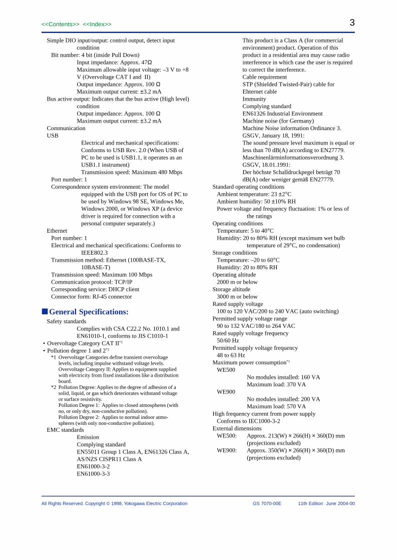
Simple DIO input/output: control output, detect inputcondition
Bit number: 4 bit (inside Pull Down)Input impedance: Approx. 47ΩMaximum allowable input voltage: –3 V to +8V (Overvoltage CAT I and II)Output impedance: Approx. 100 ΩMaximum output current: ±3.2 mA
Bus active output: Indicates that the bus active (High level)conditionOutput impedance: Approx. 100 ΩMaximum output current: ±3.2 mA
CommunicationUSB
Electrical and mechanical specifications:Conforms to USB Rev. 2.0 (When USB ofPC to be used is USB1.1, it operates as anUSB1.1 instrument)Transmission speed: Maximum 480 Mbps
Port number: 1Correspondence system environment: The model
equipped with the USB port for OS of PC tobe used by Windows 98 SE, Windows Me,Windows 2000, or Windows XP (a devicedriver is required for connection with apersonal computer separately.)
EthernetPort number: 1Electrical and mechanical specifications: Conforms to
IEEE802.3Transmission method: Ethernet (100BASE-TX,
10BASE-T)Transmission speed: Maximum 100 MbpsCommunication protocol: TCP/IPCorresponding service: DHCP clientConnector form: RJ-45 connector
General Specifications:Safety standards
Complies with CSA C22.2 No. 1010.1 andEN61010-1, conforms to JIS C1010-1
• Overvoltage Category CAT II*1
• Pollution degree 1 and 2*2
*1 Overvoltage Categories define transient overvoltagelevels, including impulse withstand voltage levels.Overvoltage Category II: Applies to equipment suppliedwith electricity from fixed installations like a distributionboard.
*2 Pollution Degree: Applies to the degree of adhesion of asolid, liquid, or gas which deteriorates withstand voltageor surface resistivity.Pollution Degree 1: Applies to closed atmospheres (withno, or only dry, non-conductive pollution).Pollution Degree 2: Applies to normal indoor atmo-spheres (with only non-conductive pollution).
EMC standardsEmissionComplying standardEN55011 Group 1 Class A, EN61326 Class A,AS/NZS CISPR11 Class AEN61000-3-2EN61000-3-3
This product is a Class A (for commercialenvironment) product. Operation of thisproduct in a residential area may cause radiointerference in which case the user is requiredto correct the interference.Cable requirementSTP (Shielded Twisted-Pair) cable forEhternet cableImmunityComplying standardEN61326 Industrial EnvironmentMachine noise (for Germany)Machine Noise information Ordinance 3.GSGV, January 18, 1991:The sound pressure level maximum is equal orless than 70 dB(A) according to EN27779.Maschinenlärminformationsverordnung 3.GSGV, 18.01.1991:Der höchste Schalldruckpegel beträgt 70dB(A) oder weniger gemäß EN27779.
Standard operating conditionsAmbient temperature: 23 ±2°CAmbient humidity: 50 ±10% RHPower voltage and frequency fluctuation: 1% or less of
the ratingsOperating conditions
Temperature: 5 to 40°CHumidity: 20 to 80% RH (except maximum wet bulb
temperature of 29°C, no condensation)Storage conditions
Temperature: –20 to 60°CHumidity: 20 to 80% RH
Operating altitude2000 m or below
Storage altitude3000 m or below
Rated supply voltage100 to 120 VAC/200 to 240 VAC (auto switching)
Permitted supply voltage range90 to 132 VAC/180 to 264 VAC
Rated supply voltage frequency50/60 Hz
Permitted supply voltage frequency48 to 63 Hz
Maximum power consumption*1
WE500No modules installed: 160 VAMaximum load: 370 VA
WE900No modules installed: 200 VAMaximum load: 570 VA
High frequency current from power supplyConforms to IEC1000-3-2
External dimensionsWE500: Approx. 213(W) × 266(H) × 360(D) mm
(projections excluded)WE900: Approx. 350(W) × 266(H) × 360(D) mm
(projections excluded)

4
All Rights Reserved. Copyright © 1998, Yokogawa Electric Corporation
<<Contents>> <<Index>>
GS 7070-00E 11th Edition June 2004-00
WeightWE500: Approx. 6.5 kg (modules excluded)WE900: Approx. 11 kg (modules excluded)
Cooling methodForced air cooling
Installation positionHorizontal
AccessoriesPower cord (1)WE7000 Control Software Setup Disk (1 CD-ROM)USB cable (2 m, conforming to USB 2.0, A type-B type) (1)15-pin D-sub connector (male) for connecting to EXT. I/OCover plates (WE500: 5 plates, WE900: 9 plates)User’s Manual (this manual) (1)
*1 Power consumption of the measuring station whenmodules are installed cannot be determined by simplysumming the power consumptions of each modulebecause the power efficiency and the power factorchanges according to the load conditions as well as to thesupply voltage and frequency.
AVAILABLE MODELS
WE500 Measuring Station (5 slots)
WE900 Measuring Station (9 slots)
100 to 240 VAC
UL, CSA Standard
VDE Standard
GB Standard
SAA Standard
BS Standard
English Help
707003
707004
-0
-D
-F
-H
-R
-Q
/HE
Model Suffix Codes Name/Description
Accessories (sold separately)
Accessory Model Specifications Orderquantity
Rack mount bracket 707861 For 707003 standalone installation 1
Rack mount bracket 707862 For 707003 ganged installation 1
Rack mount bracket 707863 For 707004 1
DimensionsWE500
213(8.39)
17 (
0.67
)11
(0.
43)
266
(10
.47)
32.5(1.28)
327.5(12.89)
15(0.59)
Unit: mm (inch)
WE900
17(0.67)
360(14.17)
17(0.67)
32.5(1.28)
327.5(12.89)
15(0.59)
266
(10.
47)
11(0
.43)
Unit: mm (inch)
WE500 JIS Rack485±1 (19.09)
100±
0.2
(3.9
4)10
0±0.
2(3
.94)
100±
0.2
(3.9
4)10
0±0.
2(3
.94)
24.5
(0.9
6)24
.5(0
.96)
282.
60 –0.3
(11
.13)
282.
60 –0
.3 (
11.1
3)
16.5
(0.6
5)16
.5(0
.65)
7(0
.28)
7(0
.28)
462.8±1 (18.22)
485±1 (19.09)462.8±1 (18.22)
Unit: mm (inch)
WE500 EIA Rack
57.2
±0.2
76.2
±0.2
57.2
±0.2
76.2
±0.2
57.1
±0.2
57.1
±0.2
37.7
(1.4
8)37
.7(1
.48)
265.
90 –0
.326
5.9
0 –0.3
7(0
.28)
7(0
.28)
485±1 (19.09)462.8±1 (18.22)
485±1 (19.09)462.8±1 (18.22)
Unit: mm (inch)
(2.2
5)(2
.25)
(2.2
5)
(3.0
)(3
.0)
(2.2
5)
(10.
47)
(10.
47)
WE900 JIS Rack485±1 (19.09)
100±
0.2
(3.9
4)10
0±0.
2(3
.94)
24.5
(0.9
6)
282.
6(1
1.13
)0 –0
.3
16.5
(0.6
5)7
(0.2
8)
462.8±1 (18.22)Unit: mm (inch)
WE900 EIA Rack
76.2
±0.2
57.1
±0.2
57.2
±0.2
0 –0.3
265.
9
37.7
(1.4
8)
(2.2
5)(3
.0)
(2.2
5)
(10.
47)
7(0
.28)
485±1 (19.09)
462.8±1 (18.22)Unit: mm (inch)
5<<Contents>> <<Index>>
All Rights Reserved. Copyright © 1998, Yokogawa Electric Corporation GS 7070-00E 11th Edition June 2004-00
WE7021
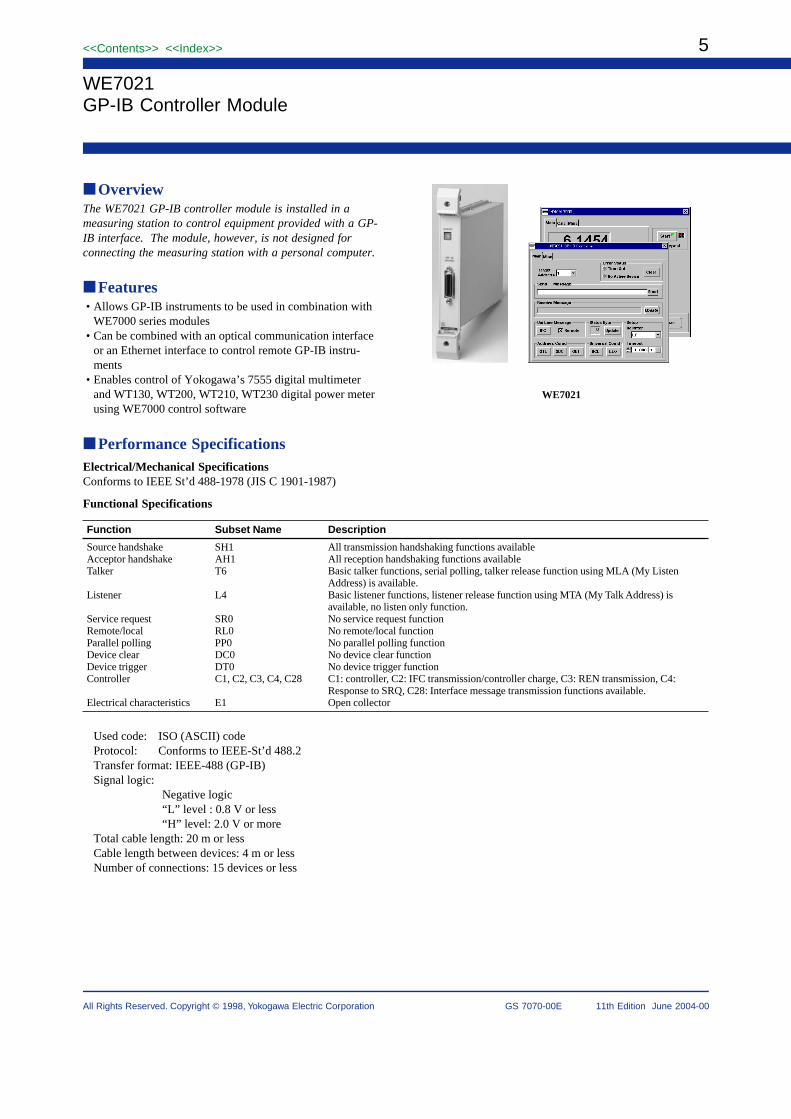
WE7021GP-IB Controller Module
OverviewThe WE7021 GP-IB controller module is installed in ameasuring station to control equipment provided with a GP-IB interface. The module, however, is not designed forconnecting the measuring station with a personal computer.
Features• Allows GP-IB instruments to be used in combination with
WE7000 series modules• Can be combined with an optical communication interface
or an Ethernet interface to control remote GP-IB instru-ments
• Enables control of Yokogawa’s 7555 digital multimeterand WT130, WT200, WT210, WT230 digital power meterusing WE7000 control software
Performance SpecificationsElectrical/Mechanical SpecificationsConforms to IEEE St’d 488-1978 (JIS C 1901-1987)
Functional Specifications
Function Subset Name Description
Source handshake SH1 All transmission handshaking functions availableAcceptor handshake AH1 All reception handshaking functions availableTalker T6 Basic talker functions, serial polling, talker release function using MLA (My Listen
Address) is available.Listener L4 Basic listener functions, listener release function using MTA (My Talk Address) is
available, no listen only function.Service request SR0 No service request functionRemote/local RL0 No remote/local functionParallel polling PP0 No parallel polling functionDevice clear DC0 No device clear functionDevice trigger DT0 No device trigger functionController C1, C2, C3, C4, C28 C1: controller, C2: IFC transmission/controller charge, C3: REN transmission, C4:
Response to SRQ, C28: Interface message transmission functions available.Electrical characteristics E1 Open collector
Used code: ISO (ASCII) codeProtocol: Conforms to IEEE-St’d 488.2Transfer format: IEEE-488 (GP-IB)Signal logic:
Negative logic“L” level : 0.8 V or less“H” level: 2.0 V or more
Total cable length: 20 m or lessCable length between devices: 4 m or lessNumber of connections: 15 devices or less

6
All Rights Reserved. Copyright © 1998, Yokogawa Electric Corporation
<<Contents>> <<Index>>
GS 7070-00E 11th Edition June 2004-00
General SpecificationsOperating conditions: Same as that of the measuring
stationStorage conditions
Temperature: –20 to 60°CHumidity: 20 to 80% RH (no condensation)
Power consumption: 1 VA (Typical value at 100 V/50 Hz(see Note))
External dimensions: Approx. 331.3(W) ×2439.54(H) × 2329.12(D)mminch (projections excluded)
Weight: Approx. 0.61.32 kglbNumber of used slots: 1Standard accessory: User’s Manual (1)
Note: Typical value represents a typical or average value.It is not strictly guaranteed.
AVAILABLE MODEL
Model Description
707021/HE GP-IB Controller Module
DimensionsUnit: mm (inch)
33(1.3)
24
2.4
(9
.54
)
227 (8.94) 4.5
(0.18)
GP-IB(IEEE488)
ADDRESS
GP-IB

7<<Contents>> <<Index>>
All Rights Reserved. Copyright © 1998, Yokogawa Electric Corporation GS 7070-00E 11th Edition June 2004-00
WE7035/WE7036Optical Interface Cards(for PC with PCI bus)
OverviewThe WE7035 and WE7036 optical interface cards areinstalled in a Windows PC with an PCI bus to allow highspeed communication between measuring stations and PC.These cards contain a CPU (32-bit RISC CPU) whichcontrols communication.
Features• High-speed data communication (250 Mbps) using optical
fiber cable• Maximum cable length: 500 meters (1640 ft)• High electromagnetic immunity• The two-port version (WE7036) allows multiple stations to
be connected in a daisy chain, or in a ring.
Functions• Remote ON/OFF control of main power on measurement
station• Auto-configuration
Specifications• Number of interface ports: 1 on WE7035, 2 on WE7036• Light source: 1300-nm LED• Connection method: Optical fiber with dual SC connector
(plural stations are connected in daisy chain)• Transmission rate: 250 Mbps• Cable length between stations: Maximum 500 meters
(1640 ft) (using optical fiber cable specified byYokogawa)
• Number of stations that can be connected: 3 stations or less• Connection fiber: Duplex multimode optical fiber with
dual SC connector (graded index silica multimode opticalfiber, core diameter; 50 µm or 62.5 µm, cladding diameter;125 µm)
• Slot: 1 PCI bus expansion slot (full size)
General Specifications• Operating condition
Operating temperature range: 5 to 40°COperating humidity range: 20 to 80% RH (no condensa-tion)
• Storage environmentStorage temperature range: –20 to 60°CStorage humidity range: 20 to 80% RH
• Current consumption: 1.4 A (typical (see Note))• Source voltage: 5 V ±10%• External dimensions: Approx. 220.94 (W) × 1265.04
(H) × 19511.97 (D) mminch (projections exclueded)• Weight: Approx. 0.30.66 kglb
Note: Typical value represents a typical or average value.It is not strictly guaranteed.
AVAILABLE MODELS
Model Description
707035 Optical Interface Card (PCI bus, 1 port)
707036 Optical Interface Card (PCI bus, 2 ports)
Accessories (sold separately)
Accessory Model SpecificationsOrder
quantity
Optical fiber cable 707831 Length: 2 meters 1
Optical fiber cable 707832 Length: 5 meters 1
Optical fiber cable 707833 Length: 10 meters 1
Optical fiber cable 707834 Length: 1 meter 1
Extension connector 707802 For optical fiber cable 1
Dimensions (WE7036)Unit: mm (inch)
21.6 (0.85)
18.4(0.72)
194.83 (7.67)174.63 (6.88)
126.
05 (
4.96
)
106.
68 (
4.2)
WE7036

8
All Rights Reserved. Copyright © 1998, Yokogawa Electric Corporation
<<Contents>> <<Index>>
GS 7070-00E 11th Edition June 2004-00
WE7037/WE7038Optical Interface Modules(for measuring stations)
OverviewThe WE7037/WE7038 optical interface modules areinstalled to a measuring station to enable high-speedcommunication between the station and a PC. Thesemodules contain a 32 bit RISC CPU that controls communi-cation.
Features• High-speed communication (250 Mbps) using optical fiber
cable• Maximum cable length: 500 meters (1640 ft)• High electromagnetic immunity• The two-port version (WE7038) allows multiple stations to
be connected in a daisy chain.
Functions• Remote ON/OFF control of module power on measure-
ment station• Auto-configuration
Standard Specifications• Number of interface ports: 1 on WE7037, 2 on WE7038• Light source: 1300-nm LED• Connection method: Optical fiber with dual SC connector
(plural stations are connected in daisy chain)• Transmission rate: 250 Mbps• Cable length between stations: Maximum 500 meters
(1640 ft) (using optical fiber cable specified byYokogawa)
• Number of stations that can be connected: 3 stations or less• LED display: Communication status, station power status• Connection fiber: Duplex multimode optical fiber with
dual SC connector (graded index silica multimode opticalfiber, core diameter; 50 µm or 62.5 µm, cladding diameter;125 µm)
• Control bus: WE bus
General Specifications• Operating condition: same as that of the measuring station.• Storage conditions
Storage temperature range: –20 to 60°CStorage humidity range: 20 to 80% RH
• Power consumption: 11 VA (typical at 100 V/50 Hz (seeNote))
• External dimensions: Approx. 331.30 (W) × 2439.57(H) × 2329.13 (D) mminch (projections exclueded)
• Weight: Approx. 0.71.54 kglb• Number of dedicated slots: 1• Accessories: User’s manual (1)
Note: Typical value represents a typical or average value.It is not strictly guaranteed.
WE7038
AVAILABLE MODELS
Model Description
707037 WE7037 Optical Interface Module (1 port)
707038 WE7038 Optical Interface Module (2 port)
Accessories (sold separately)
Accessory Model SpecificationsOrder
quantity
Optical fiber cable 707831 Length: 2 meters 1
Optical fiber cable 707832 Length: 5 meters 1
Optical fiber cable 707833 Length: 10 meters 1
Optical fiber cable 707834 Length: 1 meter 1
Extension connector 707802 For optical fiber cable 1
Dimensions (WE7038)Unit: mm (inch)
33 (1.3)
24
2.4
(9
.54
)
227 (8.94) 4.5 (0.18)

9<<Contents>> <<Index>>
All Rights Reserved. Copyright © 1998, Yokogawa Electric Corporation GS 7070-00E 11th Edition June 2004-00
WE7081CAN Bus Interface Module
OverviewThis module is used to interpret the CAN protocol andmonitor the communication data on the bus or output dataon the bus. By using this module in combination with otherWE7000 measurement modules, the changes in thecommunication data on the CAN bus and analog data suchas voltage and temperature can be measured simultaneouslyover time. The measurement results can be graphed andsaved to files.
Using the WE7000 in this fashion enables you to grasp theentire data within the system and evaluate the CAN systemas a whole.
FeaturesCAN Data Acquisition
Performs trigger measurements on the specific data of thespecified ID (up to 64 channels, up to 1 kS/s).ID, Start bit, Length, and Endian can be specified andconversion to physical values is possible.
CAN Data OutputDownload data frames and output.Manually output data of a specified ID.Construct a simple sequence function.
Module LinkingSimultaneous acquisition of CAN bus data and signals ofvarious measurement modules (analog signals) and displaythem on the same time axis.
Setup DataImport CANdb setup data.
Standard SpecificationsNumber of ports: 1Connector Type: D-Sub 9-pin (male)Controller: Philips SJA1000 CAN chipTransceiver: Built in the moduleTerminator: 124, switch the terminator On/Off using the
dipswitch on the front panelData Memory: 8 MB FIFO bufferOutput Memory: 8 MB FIFO bufferSupported Protocol
Physical layer: ISO-11898 (High Speed Communication)CAN in Automation: CAN2.0B (Standard & extended
message format)Save Format of Data: Binary file in WVF (YOKOGAWA
measurement standard) formatBinary file in WCF (WE7000 CAN BinaryFormat) formatCan be saved in binary or ASCII in CSVformat
Bit Rate: 10 k, 20 k, 33.3 k, 50 k, 62.5 k, 83.3 k, 100 k,125 k, 250 k, 500 k, 800 k, 1 Mbps, and OtherTime quanta and sample point are selectable
Endian: Little or Big selectableSynchronized Operation: Possible by sharing the trigger
signal and clock signal
General SpecificationsMaximum Measuring Input Cable Length: 30 mBasic Operating Conditions
Ambient temperature: 23±5°C,ambient humidity: 50±10% RH,
Supply voltage/frequency error: Within 1% of rating, andafter the warm-up time has passed
Warm-up Time: At least 30 minutesOperating Conditions: Same as those of the measuring
stationStorage Conditions: Temperature: –20°C to 60°C
Humidity: 20% to 80%RHPower Consumption: 5 VA (typical value* at 100 V/50
Hz)Weight: Approx. 0.7 kgExternal Dimensions:
Approx. 33(W) 243(H) 232(D) mm(projections excluded)
Number of Used Slots: 1Standard Accessories: User’s Manual (this manual) (1)
* Typical value represents a typical or average value. It isnot strictly guaranteed.
CANdb and CANdb++ are registered trademarks of VectorInformatik Gmbh.
WE7081
10
All Rights Reserved. Copyright © 1998, Yokogawa Electric Corporation
<<Contents>> <<Index>>
GS 7070-00E 11th Edition June 2004-00
Available Model
Model Description
707081 CAN Bus Interface Module
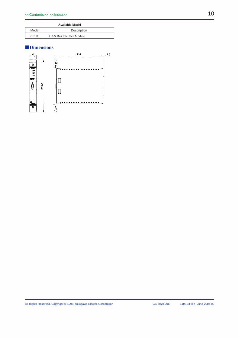
Dimensions
11<<Contents>> <<Index>>
All Rights Reserved. Copyright © 1998, Yokogawa Electric Corporation GS 7070-00E 11th Edition June 2004-00
WE7111100 MS/s Digital Oscilloscope Module
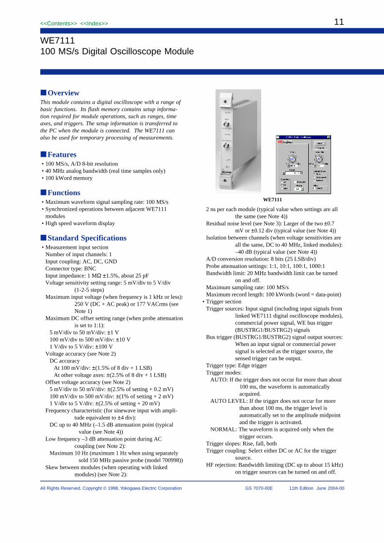
OverviewThis module contains a digital oscilloscope with a range ofbasic functions. Its flash memory contains setup informa-tion required for module operations, such as ranges, timeaxes, and triggers. The setup information is transferred tothe PC when the module is connected. The WE7111 canalso be used for temporary processing of measurements.
Features• 100 MS/s, A/D 8-bit resolution• 40 MHz analog bandwidth (real time samples only)• 100 kWord memory
Functions• Maximum waveform signal sampling rate: 100 MS/s• Synchronized operations between adjacent WE7111
modules• High speed waveform display
Standard Specifications• Measurement input section
Number of input channels: 1Input coupling: AC, DC, GNDConnector type: BNCInput impedance: 1 MΩ ±1.5%, about 25 pFVoltage sensitivity setting range: 5 mV/div to 5 V/div
(1-2-5 steps)Maximum input voltage (when frequency is 1 kHz or less):
250 V (DC + AC peak) or 177 VACrms (seeNote 1)
Maximum DC offset setting range (when probe attenuationis set to 1:1):
5 mV/div to 50 mV/div: ±1 V100 mV/div to 500 mV/div: ±10 V1 V/div to 5 V/div: ±100 V
Voltage accuracy (see Note 2)DC accuracy
At 100 mV/div: ±(1.5% of 8 div + 1 LSB)At other voltage axes: ±(2.5% of 8 div + 1 LSB)
Offset voltage accuracy (see Note 2)5 mV/div to 50 mV/div: ±(2.5% of setting + 0.2 mV)100 mV/div to 500 mV/div: ±(1% of setting + 2 mV)1 V/div to 5 V/div: ±(2.5% of setting + 20 mV)
Frequency characteristic (for sinewave input with ampli-tude equivalent to ±4 div):
DC up to 40 MHz (–1.5 dB attenuation point (typicalvalue (see Note 4))
Low frequency –3 dB attenuation point during ACcoupling (see Note 2):
Maximum 10 Hz (maximum 1 Hz when using separatelysold 150 MHz passive probe (model 700998))
Skew between modules (when operating with linkedmodules) (see Note 2):
2 ns per each module (typical value when settings are allthe same (see Note 4))
Residual noise level (see Note 3): Larger of the two ±0.7mV or ±0.12 div (typical value (see Note 4))
Isolation between channels (when voltage sensitivities areall the same, DC to 40 MHz, linked modules):–40 dB (typical value (see Note 4))
A/D conversion resolution: 8 bits (25 LSB/div)Probe attenuation settings: 1:1, 10:1, 100:1, 1000:1Bandwidth limit: 20 MHz bandwidth limit can be turned
on and off.Maximum sampling rate: 100 MS/sMaximum record length: 100 kWords (word = data-point)
• Trigger sectionTrigger sources: Input signal (including input signals from
linked WE7111 digital oscilloscope modules),commercial power signal, WE bus trigger(BUSTRG1/BUSTRG2) signals
Bus trigger (BUSTRG1/BUSTRG2) signal output sources:When an input signal or commercial powersignal is selected as the trigger source, thesensed trigger can be output.
Trigger type: Edge triggerTrigger modes:
AUTO: If the trigger does not occur for more than about100 ms, the waveform is automaticallyacquired.
AUTO LEVEL: If the trigger does not occur for morethan about 100 ms, the trigger level isautomatically set to the amplitude midpointand the trigger is activated.
NORMAL: The waveform is acquired only when thetrigger occurs.
Trigger slopes: Rise, fall, bothTrigger coupling: Select either DC or AC for the trigger
source.HF rejection: Bandwidth limiting (DC up to about 15 kHz)
on trigger sources can be turned on and off.
WE7111

12
All Rights Reserved. Copyright © 1998, Yokogawa Electric Corporation
<<Contents>> <<Index>>
GS 7070-00E 11th Edition June 2004-00
Trigger level (see Note 5)Setting range: Voltage corresponding to ± 10 div of
voltage axis sensitivitySetting resolution: 1/50 divAccuracy: ±(1 div + 10% of trigger level)
Trigger sensitivity (see Note 5) (see Note 6) (when triggersource frequency is DC to 40 MHz): 1 div
p-p
Trigger position:Setting range: +5.0 div to –5.0 divSetting resolution: 0.1 div
Trigger delay setting range: 0 to 9.99999999 sTrigger hold-off setting range: 200 ns to 9.99999999 s
• Time axisTime axis setting range: 100 ns/div to 200 ms/divTime axis accuracy (see Note 2): ±(0.01% of reading +
500 ps)External clock input (EXT CLOCK IN)
Connector type: BNCMaximum input voltage: –3 to +8 V (see Note 1)Input frequency range: 40 Hz to 15 MHz (continuous
clock only)Input level: TTL levelMinimum pulse width: 25 ns for both high and lowInput type: Non-isolated unbalanced (with 4.7 kΩ pull-
up resistance)• Functions
Auto-setup:Automatically sets voltage axis, time axis, trigger level.
Initialization: Restores the default settings.Calibration: Auto-calibration and manual calibration
availableAcquisition modes: Select from normal, envelope and
averaging.Record length: 1 kWord, 5 kWords, 10 kWords,
30 kWords, 100 kWords (100 kWords cannotbe set in averaging mode)
Input filter: 20 MHz bandwidth limitCalibration signal output: Square wave (about 1 kHz,
about 1 Vp-p
)
General SpecificationsStandard operating conditions
Ambient temperature: 23 ±2°CAmbient humidity: 50 ±10% RHSource voltage/frequency tolerance: ±1% of rating (after
warm-up time has passed)Warm-up time: Minimum 30 minutesOperating conditions: Same as that of the measuring
stationStorage conditions
Storage temperature range: –20 to 60°CStorage humidity range: 20 to 80% RH (no condensa-
tion)Power consumption: 15 VA (typical value at 100 V/50 Hz,
(see Note 4))External dimensions: Approx. 331.30 (W) × 2439.57
(H) × 2329.13 (D) mminch (projectionsexcluded)
Weight: Approx. 0.91.98 kglbNumber of dedicated slots: 1Accessories: User’s manual (1)
Note 1: Overvoltage categories CAT I and CAT IINote 2: Value measured under standard operating conditions
after calibration with the time base set to internal.Note 3: Value when the input section is shorted, record
length: 10 kWord, acquisition mode: normal mode,accumlate: OFF, probe attenuation: 1:1.
Note 4: Typical value represents a typical or average value.It is not strictly guaranteed.
Note 5: Value measured under standard operating conditionsafter calibration with the trigger signal set to a signalwith a rate of change within 10 div/s and amplitudewithin ±5 div under the following settings;Trigger mode: normal, Trigger level: within 60% ofthe amplitude of the trigger signal, HF rejection: OFF
Note 6: Value measured with the voltage sensitivity set to 50mV/div when a pulse with amplitude 5 div p-p, andrising time of 1 ns is input.Trigger coupling: DC, HF rejection: OFF
AVAILABLE MODEL
Model Description
707111/HE 100 MS/s Digital Oscilloscope Module
Accessories (sold separately)
Accessory Model SpecificationsOrder
quantity
150 MHz passive probe 700998 Band: 150 MHz 1
Miniclip converter B9852CR Probe accessory (one/unit) 1
BNC adapter B9852CS Probe accessory (one/unit) 1
Ground lead B9852CT Probe accessory (one/unit) 1
50 Ω terminal equipment 700976 Through-type 1
DimensionsUnit: mm (inch)
33 4.5(1.3)
24
2.4
(9.5
4)
227 (8.94)(0.18)
13<<Contents>> <<Index>>
All Rights Reserved. Copyright © 1998, Yokogawa Electric Corporation GS 7070-00E 11th Edition June 2004-00
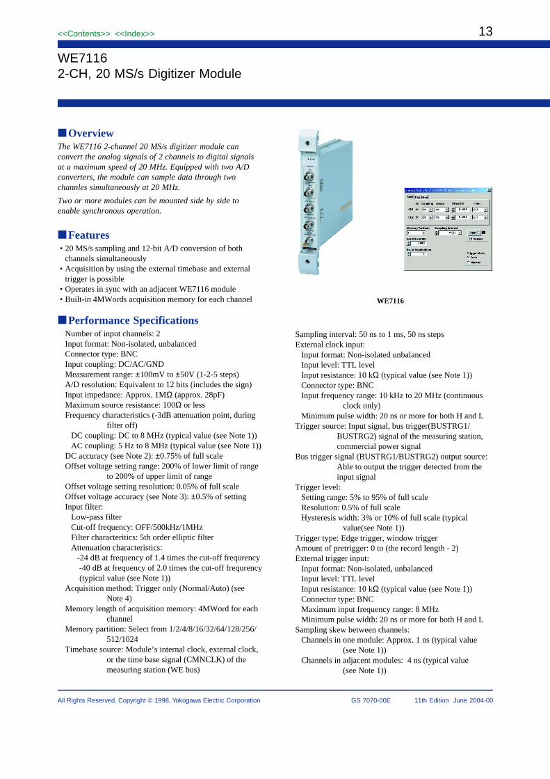
OverviewThe WE7116 2-channel 20 MS/s digitizer module canconvert the analog signals of 2 channels to digital signalsat a maximum speed of 20 MHz. Equipped with two A/Dconverters, the module can sample data through twochannles simultaneously at 20 MHz.
Two or more modules can be mounted side by side toenable synchronous operation.
Features• 20 MS/s sampling and 12-bit A/D conversion of both
channels simultaneously• Acquisition by using the external timebase and external
trigger is possible• Operates in sync with an adjacent WE7116 module• Built-in 4MWords acquisition memory for each channel
Performance SpecificationsNumber of input channels: 2Input format: Non-isolated, unbalancedConnector type: BNCInput coupling: DC/AC/GNDMeasurement range: ±100mV to ±50V (1-2-5 steps)A/D resolution: Equivalent to 12 bits (includes the sign)Input impedance: Approx. 1MΩ (approx. 28pF)Maximum source resistance: 100Ω or lessFrequency characteristics (-3dB attenuation point, during
filter off)DC coupling: DC to 8 MHz (typical value (see Note 1))AC coupling: 5 Hz to 8 MHz (typical value (see Note 1))
DC accuracy (see Note 2): ±0.75% of full scaleOffset voltage setting range: 200% of lower limit of range
to 200% of upper limit of rangeOffset voltage setting resolution: 0.05% of full scaleOffset voltage accuracy (see Note 3): ±0.5% of settingInput filter:
Low-pass filterCut-off frequency: OFF/500kHz/1MHzFilter characteritics: 5th order elliptic filterAttenuation characteristics:
-24 dB at frequency of 1.4 times the cut-off frequrency -40 dB at frequency of 2.0 times the cut-off frequrency
(typical value (see Note 1))Acquisition method: Trigger only (Normal/Auto) (see
Note 4)Memory length of acquisition memory: 4MWord for each
channelMemory partition: Select from 1/2/4/8/16/32/64/128/256/
512/1024Timebase source: Module’s internal clock, external clock,
or the time base signal (CMNCLK) of themeasuring station (WE bus)
Sampling interval: 50 ns to 1 ms, 50 ns stepsExternal clock input:
Input format: Non-isolated unbalancedInput level: TTL levelInput resistance: 10 kΩ (typical value (see Note 1))Connector type: BNCInput frequency range: 10 kHz to 20 MHz (continuous
clock only)Minimum pulse width: 20 ns or more for both H and L
Trigger source: Input signal, bus trigger(BUSTRG1/BUSTRG2) signal of the measuring station,commercial power signal
Bus trigger signal (BUSTRG1/BUSTRG2) output source:Able to output the trigger detected from theinput signal
Trigger level:Setting range: 5% to 95% of full scaleResolution: 0.5% of full scaleHysteresis width: 3% or 10% of full scale (typical
value(see Note 1))Trigger type: Edge trigger, window triggerAmount of pretrigger: 0 to (the record length - 2)External trigger input:
Input format: Non-isolated, unbalancedInput level: TTL levelInput resistance: 10 kΩ (typical value (see Note 1))Connector type: BNCMaximum input frequency range: 8 MHzMinimum pulse width: 20 ns or more for both H and L
Sampling skew between channels:Channels in one module: Approx. 1 ns (typical value
(see Note 1))Channels in adjacent modules: 4 ns (typical value
(see Note 1))
WE7116
WE71162-CH, 20 MS/s Digitizer Module

14
All Rights Reserved. Copyright © 1998, Yokogawa Electric Corporation
<<Contents>> <<Index>>
GS 7070-00E 11th Edition June 2004-00
General SpecificationsSafety standards: Complies with CSA C22.2 No. 1010.1
and EN61010-1, conforms to JIS C1010-1Warm-up time: At least 30 minutesMaximum allowable input voltage:
Channel input: ±250 V (DC + AC peak) or 177 VrmsExternal clock input: -3 V to 8 VExternal trigger input: -3 V to 8V(Overvoltage category: CAT I and II)
Operating conditions: Same as those of the measuringstation
Storage conditions:Temperature: -20°C to 60°CHumidity: 20% to 80% RH (no condensation)
Power consumption: 10 VA (typical value (see Note 1) at100 V/50 Hz)
Weight: Approx. 0.71.54 kglbExternal dimensions: Approx. 331.3(W) × 2439.54(H)
× 2329.13(D) mminch (projectionsexcluded)
Number of used slots: 1Standard accessories: User’s Manual (1)
Note 1: Typical value represents a typical or average value. Itis not strictly guaranteed.
Note 2: Value measured with offset voltage set to 0 V andtime base set to internal clock under ambienttemperature:23±5°C, ambient humidity: 50±10%RH, after warm-up time has passed and after offsetcalibration.
Note 3: Value measured with time base set to internal clockunder ambient temperature:23±5°C,ambienthumidity: 50±10% RH, after warm-up time haspassed and after offset calibration.
Note 4: Freerun mode and gate mode are not supported.
AVAILABLE MODELS
Model Description
707116 2-CH, 20 MS/s Digitizer Module
Special Accessories(sold separately)
1
1
1
1
1
400 MHz passive probe
Miniclip converter
BNC adapter
Ground lead
50 Ω terminal equipment
700988
B9852CR
B9852CS
B9852CT
700976
10:1 or 1:1 selectable, 1.5 m Probe accessory (one/unit) Probe accessory (one/unit) Probe accessory (one/unit)
Through-type
ModelAccessory DescriptionOrder
quantity
Dimensions
33(1.3)
24
2.4
(9
.54
)
227 (8.94) 4.5(0.18)
Unit: mm (inch)
15<<Contents>> <<Index>>
All Rights Reserved. Copyright © 1998, Yokogawa Electric Corporation GS 7070-00E 11th Edition June 2004-00
WE7121
WE712110 MHz Function Generator Module
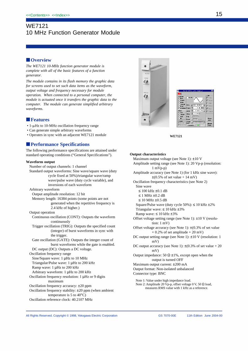
OverviewThe WE7121 10-MHz function generator module iscomplete with all of the basic features of a functiongenerator.
The module contains in its flash memory the graphic datafor screens used to set such data items as the waveform,output voltage and frequency necessary for moduleoperation. When connected to a personal computer, themodule is actuated once it transfers the graphic data to thecomputer. The module can generate simplified arbitrarywaveforms.
Features• 1-Hz to 10-MHz oscillation frequency range• Can generate simple arbitrary waveforms• Operates in sync with an adjacent WE7121 module
Performance SpecificationsThe following performance specifications are attained understandard operating conditions (“General Specifications”).
Waveform outputNumber of output channels: 1 channelStandard output waveforms: Sine wave/square wave (duty
cycle fixed at 50%)/triangular wave/rampwave/pulse wave (duty cycle variable), andinversions of each waveform
Arbitrary waveformOutput amplitude resolution: 12 bitMemory length: 16384 points (some points are not
generated when the repetitive frequency is2.4 kHz of higher.)
Output operationContinuous oscillation (CONT): Outputs the waveform
continuouslyTrigger oscillation (TRIG): Outputs the specified count
(integer) of burst waveforms in sync withthe trigger.
Gate oscillation (GATE): Outputs the integer count ofburst waveforms while the gate is enabled.
DC output (DC): Outputs a DC voltage.Oscillation frequency range
Sine/Square wave: 1 µHz to 10 MHzTriangular/Pulse wave: 1 µHz to 200 kHzRamp wave: 1 µHz to 200 kHzArbitrary waveform: 1 µHz to 200 kHz
Oscillation frequency resolution: 1 µHz or 9 digitsmaximum
Oscillation frequency accuracy: ±20 ppmOscillation frequency stability: ±20 ppm (when ambient
temperature is 5 to 40°C)Oscillation reference clock: 40.2107 MHz
Output characteristicsMaximum output voltage (see Note 1): ±10 VAmplitude setting range (see Note 1): 20 Vp-p (resolution:
1 mVp-p)Amplitude accuracy (see Note 1) (for 1 kHz sine wave):
±(0.5% of set value + 14 mV)Oscillation frequency characteristics (see Note 2)
Sine wave≤ 100 kHz ±0.1 dB≤ 1 MHz ±0.2 dB≤ 10 MHz ±0.5 dB
Square/Pulse wave (duty cycle 50%): ≤ 10 kHz ±2%Triangular wave: ≤ 10 kHz ±3%Ramp wave: ≤ 10 kHz ±3%
Offset voltage setting range (see Note 1): ±10 V (resolu-tion: 1 mV)
Offset voltage accuracy (see Note 1): ±(0.3% of set value+ 0.2% of set amplitude + 20 mV)
DC output setting range (see Note 1): ±10 V (resolution: 1mV)
DC output accuracy (see Note 1): ±(0.3% of set value + 20mV)
Output impedance: 50 Ω ±1%, except open when theoutput is turned OFF
Maximum output current: ±200 mAOutput format: Non-isolated unbalancedConnector type: BNC
Note 1: Value under high impedance load.Note 2: Amplitude 20 Vp-p, offset voltage 0 V, 50 Ω load,
measures RMS value with 1 kHz as a reference.

16
All Rights Reserved. Copyright © 1998, Yokogawa Electric Corporation
<<Contents>> <<Index>>
GS 7070-00E 11th Edition June 2004-00
Sine wave purityHarmonics (see Note) (Maximum value of the 2nd to 5th
order harmonic components)100 kHz: –55 dBc or less1 MHz: –45 dBc or less10 MHz: –35 dBc or less
Harmonic distortion (see Note) (RMS value of 2nd to 5thorder harmonic components)
100 kHz: 0.3% or lessSpurious response (see Note) (frequency range 1 kHz to
100 MHz)100 kHz: –55 dBc or less
Note: Measured with 20 Vp-p amplitude, 0 V offset voltage,50 Ω load.
Characteristics of sine, pulse, triangular wavesRise time (see Note)
Square wave: 30 ns or less (10% - 90%)Pulse wave: 100 ns or less (10% - 90%)
Overshoot (see Note): ±5% or less of the output p-p valueDuty cycle setting (pulse wave only)
Setting range: 0 to 100% (resolution: 0.01% or 25 ns)Time accuracy (≤ 10 kHz): ±0.2% of (1/set frequency)Jitter: 1 clock cycle
Note: Measured with 20 Vp-p amplitude, 0 V offset voltage,50 Ω load.
PhaseTarget: Start/stop phase when using trigger/gate
oscillationSetting range: –10000 deg to +10000 deg (resolution: 0.01
deg)
Trigger/GateTrigger source: Internal trigger, Bus trigger (BUSTRG1/
BUSTRG2) signal on WE busSetting range of internal trigger frequency: 1 mHz to 50
kHz (resolution: 1 mHz)Bus trigger (BUSTRG1/BUSTRG2) signal output source:
Able to output waveform synchronizationoutput (SYNC) signal
Setting range of burst count: 1 to 65535 counts (step: 1)Gate source: Bus trigger (BUSTRG1/BUSTRG2) signal on
the WE bus
Synchronous operationSkew between modules (when modules are linked and
outputting the pulse wave): 70 ns per module(Typical value (see Note 1))
Isolation between channels (see Note 2) (when modulesare linked): –65 dB (Typical value (see Note1))
Note 1: Typical value represents a typical or average value.It is not strictly guaranteed.
Note 2: Output waveform: Cross talk for a 10 MHz sinewave with 20 Vp-p amplitude, 0 V offset voltage, 50Ω load.
Specifications of the Auxiliary OutputWaveform synchronization signal output (SYNC OUT)
Output level: TTL level, under high impedance loadOutput impedance: Approx. 50 ΩMaximum output current: ±3.2 mAOutput format: Non-isolated unbalancedConnector type: BNC
General SpecificationsStandard operating conditions
Ambient temperature: 23 ±2°C, Ambient humidity: 50±10% RH, Error on supply voltage/frequency: within 1% of rating, after thewarm-up time has passed
Warm-up time: At least 30 minutesOperating conditions: Same as that of the measuring
stationStorage conditions
Temperature: –20°C to 60°CHumidity: 20% to 80% RH (no condensation)
Power consumption: 7 VA (Typical value at 100 V/50 Hz(see Note))
External dimensions: Approx. 331.3 (W) × 2439.54(H) × 2329.12 (D) mminch (projectionsexcluded)
Weight: Approx. 0.71.54 kglbNumber of dedicated slots: 1Standard accessory: User’s Manual (1)Optional accessory
366924 BNC cable (1 m)366925 BNC cable (2 m)366926 BNC alligator clip cable (1 m)366921 Adapter (BNC plug-banana terminal jack)366927 Adapter (BNC plug-RCA jack)366928 Adapter (BNC jack-RCA plug)
Note: Typical value represents a typical or average value. Itis not strictly guaranteed.
AVAILABLE MODEL
Model Description
707121/HE 10 MHz Function Generator Moule
DimensionsUnit: mm (inch)
33(1.3)
24
2.4
(9
.54
)
227 (8.94) 4.5
(0.18)

17<<Contents>> <<Index>>
All Rights Reserved. Copyright © 1998, Yokogawa Electric Corporation GS 7070-00E 11th Edition June 2004-00
WE7141100 MHz Universal Counter Module
OverviewThe WE7141 is a universal counter module with a limitedrange of basic functions. Its flash memory contains setupinformation required for module operations, such as rangesand gate times. The setup information is transferred to thePC when the module is connected.
Features• Measurement of frequencies from 1 Hz to 120 MHz• Wide variety of measurement functions (time interval,
pulse width, duty factor, totalization, etc.)• D/A output function• Auto-trigger function
Input Section Specifications• Number of input channels: 2 (A, B)• Input format: Non-isolated unbalanced• Connector type: BNC• Input impednance: 1 MΩ, 40 pF (Typical value (see Note
1))• Input coupling: DC, AC• Low frequency: –3 dB point during AC coupling: 35 Hz
(Typical value (see Note 1))• Attenuator: ×1, ×10• Trigger level
When the attenuator is set to ×1: –5 V to +5 V (resolution:20 mV)
When the attenuator is set to ×10: –40 V to +40 V(resolution: 200 mV)
Setting accuracy (see Note 2): ±10% ±30 mV of the setvalue (When the attenuator is set to ×1)
• Trigger slope: Rise, Fall• Auto trigger: Automatically set to the center value of the
input amplitudeOperation frequency range: Sine wave 50 Hz to 120 MHz
(sensitivity: 250 mVrms)Operation voltage range: ±5 V (When the attenuator is set
to ×1)• Input sensitivity (see Note 2)
50 mVrms: DC < input frequency ≤ 60 MHz100 mVrms: 60MHz < input frequency ≤ 120 MHz
• Maximum input voltage40 V (DC + ACpeak): DC ≤ input frequency < 4 MHz
( 140 +5) [V (DC + ACpeak)] [ ]f MHz
4 MHz ≤ input frequency < 120 MHz(Overvoltage Category: CAT I and II)
• Channel B gateGate signal used during frequency A and totalize countmeasurementsInput range: Gate setting pulse width is 100 ns to 100 s(The number of input cycles of channel A within the gatetime does not exceed 232 counts.)
Gate time of channel B > One period of the input signal ofchannel A
• Minimum input pulse width (see Note 2): 10 ns (exceptwhen using 1/2 prescaler)
Note 1: Typical value represents a typical or average value.It is not strictly guaranteed.
Note 2: Value or allowed value obtained during standardoperating conditions.
Specifications for Individual Measurement Func-tions
Frequency A• Measurement range: 1 Hz to 120 MHz(when using 1/2
prescaler), 1 mHz to 60 MHz• Gate time (see Note 1)
When using prescaler: 10 ms, 100 ms, 1 s, 10 sWhen not using prescaler: 10 ms, 100 ms, 1 s, 10 s, CH B
gate (channel B pulse width)• Resolution:
±10 ns ± 2 × Trigger error (see Note 3)Gate time × Measurement
frequency (Hz)• Accuracy (see Note 2): Resolution ±(Time base aging ×
measurement frequency)[Hz]
Period A• Measurement range: 20 ns to 999.999999 s• Multiplier: 1, 10, 100, 1000• Resolution
±10 ns ± 2 × Trigger error (see Note 3)(s)
N10
(10N denotes the multiplier (N = 0, 1, 2, 3).)• Accuracy (see Note 2): Resolution ±(time-base aging ×
measurement period) (seconds)
Time Interval A → B• Measurement range: 60 ns to 999.999999 s• Input frequency range: 1 mHz to 50 MHz (for input
channels A and B)
WE7141
18
All Rights Reserved. Copyright © 1998, Yokogawa Electric Corporation
<<Contents>> <<Index>>
GS 7070-00E 11th Edition June 2004-00
• Multiplier: 1, 10, 100, 1000• Measurement suspension time: 200 ns (when multiplier =
10, 100, 1000)• Resolution:
±10 ns ±Channel A input trigger error ± Channel B input trigger error
(s)N10
(see Note 3) (see Note 3)
(10N denotes the multiplier (N = 0, 1, 2, 3).)• Accuracy (see Note 2): Resolution ±(Time base aging ×
measurement time) ±trigger level timing error (see Note 4)±10 ns error between channels (see Note 5)
Pulse Width A• Measurement range: 20 ns to 999.999999 s• Multiplier: 1, 10, 100, 1000• Resolution:
±10 ns ±Rising edge trigger error ± Falling edge trigger error(s)N
10
(see Note 3) (see Note 3)
(10N denotes the multiplier (N = 0, 1, 2, 3).)• Accuracy (see Note 2): Resolution ±(Time base aging ×
measurement time) ±trigger level timing error (see Note 4)
Duty Cycle A• Measurement range: 0.00000001 to 0.99999999• Input range: 20 ns to 999.999999 s• Multiplier: 1, 10, 100, 1000• Displayed units: Value is displayed as a ratio (50% is
displayed as 0.5)• Resolution:
Pulse width + Pulse width resolutionPeriod – Period resolution
– measured duty value)±(
• Accuracy (see Note 2):Pulse width + Pulse width accuracy
Period – Period accuracy– measured duty value)±(
Frequency Ratio A/B• Measurement range: 0.001 to 999999999 (When multiplier
=1, 0 is displayed when frequency A < B)• Input range: 1 mHz to 60 MHz• Multiplier: 1, 10, 100, 1000• Resolution:
±Channel A input 1 count ± 2 × Channel B input trigger errorN
10
(see Note 3)
(10N denotes the multiplier (N = 0, 1, 2, 3).)• Accuracy (see Note 2): Same as the resolution
Totalized Count A• Input frequency range: 1 mHz to 50 MHz• Counting capacity: 0 to 252 (except 0 to 109 on the
WE7000 Control Software)• Counting error: ±1 count during channel B gate measurement• Counting control: Manual start or channel B gate (pulse
width)
Continuous Measurement• Sampling interval: 10 ms to 100000 s (see Note 6)
10 ms step• Trigger output mode: Rise / Fall / In / Out
Note 1: When one period of the input frequency is greaterthan or equal to the set gate time, the gate time is thetime over one period of the input signal.
Note 2: Value obtained under standard operating conditions.Values outside the measurement range are notguaranteed.
Note 3: X En
Trigger error = [S]S.R
+2 2
X: Counter input section noise = 600[µVrms], En:Signal noise [Vrms] within the input amp bandwidth(120 MHz), SR: Slew rate of the input signal at thetrigger level [V/s]
Note 4: Trigger level timing error
20mV= ( )–
S.R (START)20mV
S.R (STOP)
± ( ± [S]S.R (START) S.R (STOP)
Trigger level setting accuracy Trigger level setting accuracy
SR(START): Slew rate of the input signal of channelA at the trigger level [V/s](Time interval measure-ment)Slew rate of the rising/falling slopes [V/s](pulsewidth measurement)SR(STOP): Slew rate of the input signal of channel Bat the trigger level [V/s](Time interval measurement)Slew rate of the rising/falling slopes [V/s](pulsewidth measurement)
Note 5: 10 ns error between channels: Error due to thedifference in the internal delay of channels A and B.
Note 6: When four or more WE7141 or WE7262 modulesare put into operation for continuous measurement,the sampling interval of each module must be set tono shorter than 20 ms.
External Input/Output SpecificationsD/A Output• Output voltage range: 0 to +10 V(under high impedance
load)Linear conversion, full scale 15 bit D/A
• Range setting range: Set the maximum and minimumvalues of the range to perform D/A conversionSetting range: 0 to 252 (except 0 to 109 on the WE7000
Control Software)• Maximum output current: ±2 mA• Output format: Non-isolated unbalanced• Connector type: BNC
Reference Time Specifications• Internal reference frequency: 10 MHz• Frequency stability (see Note 1)
Aging rate: ±1.5 ×10⁻⁶ /yrTemperature characteristics: ±3 ×10⁻⁶ (5°C to 40°C)
• Reference outputConnector type: BNCOutput coupling: ACOutput impedance: 50 Ω (Typical value (see Note 2))Output frequency: 10 MHz (Typical value (see Note 2))Output level: 1 Vp-p or more (under 50 Ω load)
• External reference input (see Note 1)Connector type: BNCInput coupling: ACInput impedance: 1 kΩ or moreInput frequency range: 10 MH ±10 HzInput level: 1 Vp-p or moreMaximum input voltage: ±10 V (Overvoltge Category:
CAT I and II)
Note 1: Value or allowed value obtained during standardoperating conditions.
Note 2: Typical value represents a typical or average value.It is not strictly guaranteed.

19<<Contents>> <<Index>>
All Rights Reserved. Copyright © 1998, Yokogawa Electric Corporation GS 7070-00E 11th Edition June 2004-00
General Specifications• Standard operating conditions
Temperature: 23 ±2°C, humidity: 50 ±10% RH,Power voltage/frequency error: within 1% of rating, after
the warmup time has passed• Warmup time: At least 30 minutes• Operating conditions: Same as those of the measuring
station• Storage conditions
Temperature: –20 to 60°CHumidity: 20 to 80% RH
• Power consumption: 6 VA (Typical value at 100 V/50 Hz(see Note))
• External dimensions: Approx. 331.30 (W) × 2439.57(H) × 2329.13 (D) mminch) (projections excluded)
• Weight: Approx. 0.7 1.54 kglb• Number of used slots: 1• Standard accessory: User’s Manual (1)• Optional accessories
700976 50 Ω terminator366921 Adapter (BNC plug - banana terminal jack)366923 Connection adapter (T-shaped BNC)366924 BNC cable (1 m (3.28 ft))366925 BNC cable (2 m (6.56 ft))366926 BNC alligator clip cable (1 m (3.28 ft))
Note: Typical value represents a typical or average value. Itis not strictly guaranteed.
AVAILABLE MODEL
Model Description
707141/HE 100 MHz Universal Counter Module
DimensionsUnit: mm (inch)
33 4.5(1.3)
24
2.4
(9.5
4)
227 (8.94)(0.18)
20
All Rights Reserved. Copyright © 1998, Yokogawa Electric Corporation
<<Contents>> <<Index>>
GS 7070-00E 11th Edition June 2004-00
WE72354-CH 100 kS/s Accelerometer Module
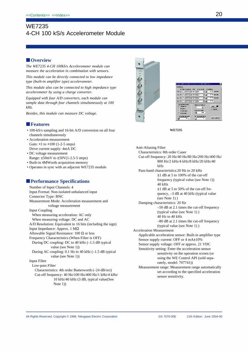
OverviewThe WE7235 4-CH 100kS/s Accelerometer module canmeasure the acceleration in combination with sensors.
This module can be directly connected to low impedancetype (built-in amplifier type) accelerometer.
This module also can be connected to high impedance typeaccelerometer by using a charge converter.
Equipped with four A/D converters, each module cansample data through four channels simultaneously at 100kHz.
Besides, this module can measure DC voltage.
Features• 100-kS/s sampling and 16-bit A/D conversion on all four
channels simultaneously• Acceleration measurement
Gain: ×1 to ×100 (1-2-5 steps)Drive current supply: 4mA DC
• DC voltage measurementRange: ±50mV to ±50V(1-2.5-5 steps)
• Built-in 4MWords acquisition memory• Operates in sync with an adjacent WE7235 module
Performance SpecificationsNumber of Input Channels: 4Input Format: Non-isolated unbalanced inputConnector Type: BNCMeasurement Mode: Acceleration measurement and
voltage measurementInput Coupling
When measuring acceleration: AC onlyWhen measuring voltage: DC and AC
A/D Resolution: Equivalent to 16 bits (including the sign)Input Impedance: Approx. 1 MΩAllowable Signal Resistance: 100 Ω or lessFrequency Characteristics (When Filter is OFF)
During DC coupling: DC to 40 kHz (–1.5 dB typicalvalue (see Note 1))
During AC coupling: 0.1 Hz to 40 kHz (–1.5 dB typicalvalue (see Note 1))
Input FilterLow-pass Filter
Characteristics: 4th order Butterworth (–24 dB/oct)Cut-off frequency: 40 Hz/100 Hz/400 Hz/1 kHz/4 kHz/
10 kHz/40 kHz (3 dB, typical value(SeeNote 1))
WE7235
Anti-Aliasing FilterCharacteristics: 8th order CauerCut-off frequency: 20 Hz/40 Hz/80 Hz/200 Hz/400 Hz/
800 Hz/2 kHz/4 kHz/8 kHz/20 kHz/40kHz
Pass-band characteristics:20 Hz to 20 kHz±1 dB at 5 to 100% of the cut-offfrequency (typical value (see Note 1))40 kHz±1 dB at 5 to 50% of the cut-off fre-quency, –3 dB at 40 kHz (typical value(see Note 1) )
Damping characteristics: 20 Hz–50 dB at 2.1 times the cut-off frequency(typical value (see Note 1) )40 Hz to 40 kHz–80 dB at 2.1 times the cut-off frequency(typical value (see Note 1) )
Acceleration MeasurementApplicable acceleration sensor: Built-in amplifier typeSensor supply current: OFF or 4 mA±10%Sensor supply voltage: OFF or approx. 21 VDCSensitivity setting: Enter the acceleration sensor
sensitivity on the operation screen (orusing the WE Control API (sold sepa-rately, model: 707741))
Measurement range: Measurement range automaticallyset according to the specified accelerationsensor sensitivity.
21<<Contents>> <<Index>>
All Rights Reserved. Copyright © 1998, Yokogawa Electric Corporation GS 7070-00E 11th Edition June 2004-00
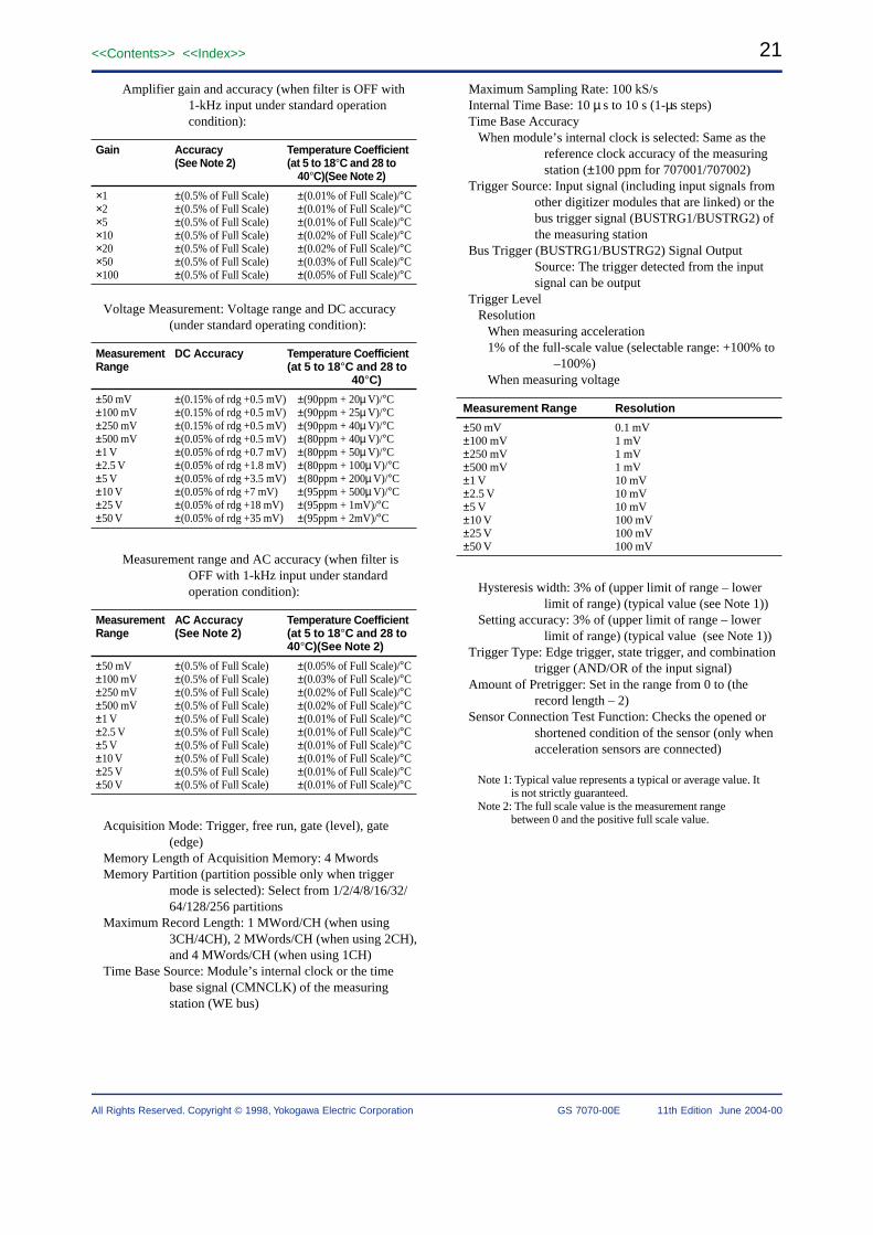
Amplifier gain and accuracy (when filter is OFF with1-kHz input under standard operationcondition):
Gain Accuracy Temperature Coefficient(See Note 2) (at 5 to 18°C and 28 to
40°C)(See Note 2)
×1 ±(0.5% of Full Scale) ±(0.01% of Full Scale)/°C×2 ±(0.5% of Full Scale) ±(0.01% of Full Scale)/°C×5 ±(0.5% of Full Scale) ±(0.01% of Full Scale)/°C×10 ±(0.5% of Full Scale) ±(0.02% of Full Scale)/°C×20 ±(0.5% of Full Scale) ±(0.02% of Full Scale)/°C×50 ±(0.5% of Full Scale) ±(0.03% of Full Scale)/°C×100 ±(0.5% of Full Scale) ±(0.05% of Full Scale)/°C
Voltage Measurement: Voltage range and DC accuracy(under standard operating condition):
Measurement DC Accuracy Temperature CoefficientRange (at 5 to 18°C and 28 to
40°C)
±50 mV ±(0.15% of rdg +0.5 mV) ±(90ppm + 20µ V)/°C±100 mV ±(0.15% of rdg +0.5 mV) ±(90ppm + 25µ V)/°C±250 mV ±(0.15% of rdg +0.5 mV) ±(90ppm + 40µ V)/°C±500 mV ±(0.05% of rdg +0.5 mV) ±(80ppm + 40µ V)/°C±1 V ±(0.05% of rdg +0.7 mV) ±(80ppm + 50µ V)/°C±2.5 V ±(0.05% of rdg +1.8 mV) ±(80ppm + 100µ V)/°C±5 V ±(0.05% of rdg +3.5 mV) ±(80ppm + 200µ V)/°C±10 V ±(0.05% of rdg +7 mV) ±(95ppm + 500µ V)/°C±25 V ±(0.05% of rdg +18 mV) ±(95ppm + 1mV)/°C±50 V ±(0.05% of rdg +35 mV) ±(95ppm + 2mV)/°C
Measurement range and AC accuracy (when filter isOFF with 1-kHz input under standardoperation condition):
Measurement AC Accuracy Temperature CoefficientRange (See Note 2) (at 5 to 18°C and 28 to
40°C)(See Note 2)
±50 mV ±(0.5% of Full Scale) ±(0.05% of Full Scale)/°C±100 mV ±(0.5% of Full Scale) ±(0.03% of Full Scale)/°C±250 mV ±(0.5% of Full Scale) ±(0.02% of Full Scale)/°C±500 mV ±(0.5% of Full Scale) ±(0.02% of Full Scale)/°C±1 V ±(0.5% of Full Scale) ±(0.01% of Full Scale)/°C±2.5 V ±(0.5% of Full Scale) ±(0.01% of Full Scale)/°C±5 V ±(0.5% of Full Scale) ±(0.01% of Full Scale)/°C±10 V ±(0.5% of Full Scale) ±(0.01% of Full Scale)/°C±25 V ±(0.5% of Full Scale) ±(0.01% of Full Scale)/°C±50 V ±(0.5% of Full Scale) ±(0.01% of Full Scale)/°C
Acquisition Mode: Trigger, free run, gate (level), gate(edge)
Memory Length of Acquisition Memory: 4 MwordsMemory Partition (partition possible only when trigger
mode is selected): Select from 1/2/4/8/16/32/64/128/256 partitions
Maximum Record Length: 1 MWord/CH (when using3CH/4CH), 2 MWords/CH (when using 2CH),and 4 MWords/CH (when using 1CH)
Time Base Source: Module’s internal clock or the timebase signal (CMNCLK) of the measuringstation (WE bus)
Maximum Sampling Rate: 100 kS/sInternal Time Base: 10 µ s to 10 s (1-µs steps)Time Base Accuracy
When module’s internal clock is selected: Same as thereference clock accuracy of the measuringstation (±100 ppm for 707001/707002)
Trigger Source: Input signal (including input signals fromother digitizer modules that are linked) or thebus trigger signal (BUSTRG1/BUSTRG2) ofthe measuring station
Bus Trigger (BUSTRG1/BUSTRG2) Signal OutputSource: The trigger detected from the inputsignal can be output
Trigger LevelResolution
When measuring acceleration1% of the full-scale value (selectable range: +100% to
–100%)When measuring voltage
Measurement Range Resolution
±50 mV 0.1 mV±100 mV 1 mV±250 mV 1 mV±500 mV 1 mV±1 V 10 mV±2.5 V 10 mV±5 V 10 mV±10 V 100 mV±25 V 100 mV±50 V 100 mV
Hysteresis width: 3% of (upper limit of range – lowerlimit of range) (typical value (see Note 1))
Setting accuracy: 3% of (upper limit of range – lowerlimit of range) (typical value (see Note 1))
Trigger Type: Edge trigger, state trigger, and combinationtrigger (AND/OR of the input signal)
Amount of Pretrigger: Set in the range from 0 to (therecord length – 2)
Sensor Connection Test Function: Checks the opened orshortened condition of the sensor (only whenacceleration sensors are connected)
Note 1: Typical value represents a typical or average value. Itis not strictly guaranteed.
Note 2: The full scale value is the measurement rangebetween 0 and the positive full scale value.

22
All Rights Reserved. Copyright © 1998, Yokogawa Electric Corporation
<<Contents>> <<Index>>
GS 7070-00E 11th Edition June 2004-00
General SpecificationsSafety Standards: Complies with CSA C22.2 No.1010.1
and EN61010-1, conforms to JIS C1010-1Warm-up Time: At least 30 minutesMaximum Allowable Input Voltage: ±60 V (DC + AC
peak)Operating Conditions: Same as those of the measuring
stationStorage Conditions
Temperature: –20°C to 60°CHumidity: 20% to 80% RH (no condensation)
Power Consumption: 12 VA (typical value at 100 V/50 Hz(see Note 3))
Weight: Approx. 0.81.76 kg lbExternal Dimensions: Approx. 331.3(W) ×
2439.54(H) × 2329.13(D) mm inch(projections excluded)
Number of Used Slots: 1Standard Accessories: User’s Manual (this manual) (1)
Note 3: Typical value represents a typical or average value. Itis not strictly guaranteed.
AVAILABLE MODEL
Model Description
707235/HE 4-CH, 100 kS/s Accelerometer Module
Dimensions
33
(1.3)
24
2.4
(9
.54
)
227 (8.94) 4.5
(0.18)
START
INPUTS
CH1
CH2
CH3
CH4
60VpkCAT
4-CH 100kS/sACCELEROMETER
1M
Unit: mm (inch)
23<<Contents>> <<Index>>
All Rights Reserved. Copyright © 1998, Yokogawa Electric Corporation GS 7070-00E 11th Edition June 2004-00
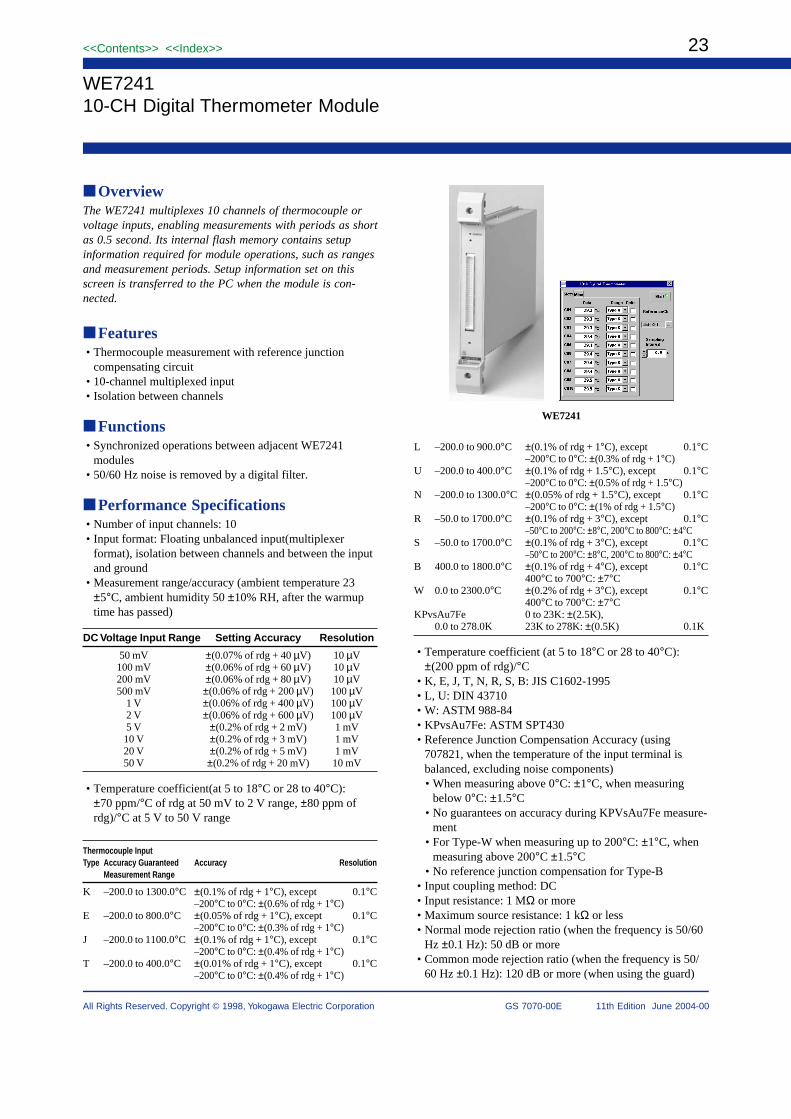
WE724110-CH Digital Thermometer Module
OverviewThe WE7241 multiplexes 10 channels of thermocouple orvoltage inputs, enabling measurements with periods as shortas 0.5 second. Its internal flash memory contains setupinformation required for module operations, such as rangesand measurement periods. Setup information set on thisscreen is transferred to the PC when the module is con-nected.
Features• Thermocouple measurement with reference junction
compensating circuit• 10-channel multiplexed input• Isolation between channels
Functions• Synchronized operations between adjacent WE7241
modules• 50/60 Hz noise is removed by a digital filter.
Performance Specifications• Number of input channels: 10• Input format: Floating unbalanced input(multiplexer
format), isolation between channels and between the inputand ground
• Measurement range/accuracy (ambient temperature 23±5°C, ambient humidity 50 ±10% RH, after the warmuptime has passed)
DC Voltage Input Range Setting Accuracy Resolution
50 mV ±(0.07% of rdg + 40 µV) 10 µV100 mV ±(0.06% of rdg + 60 µV) 10 µV200 mV ±(0.06% of rdg + 80 µV) 10 µV500 mV ±(0.06% of rdg + 200 µV) 100 µV
1 V ±(0.06% of rdg + 400 µV) 100 µV2 V ±(0.06% of rdg + 600 µV) 100 µV5 V ±(0.2% of rdg + 2 mV) 1 mV10 V ±(0.2% of rdg + 3 mV) 1 mV20 V ±(0.2% of rdg + 5 mV) 1 mV50 V ±(0.2% of rdg + 20 mV) 10 mV
• Temperature coefficient(at 5 to 18°C or 28 to 40°C):±70 ppm/°C of rdg at 50 mV to 2 V range, ±80 ppm ofrdg)/°C at 5 V to 50 V range
Thermocouple InputType Accuracy Guaranteed Accuracy Resolution
Measurement Range
K –200.0 to 1300.0°C ±(0.1% of rdg + 1°C), except 0.1°C–200°C to 0°C: ±(0.6% of rdg + 1°C)
E –200.0 to 800.0°C ±(0.05% of rdg + 1°C), except 0.1°C–200°C to 0°C: ±(0.3% of rdg + 1°C)
J –200.0 to 1100.0°C ±(0.1% of rdg + 1°C), except 0.1°C–200°C to 0°C: ±(0.4% of rdg + 1°C)
T –200.0 to 400.0°C ±(0.01% of rdg + 1°C), except 0.1°C–200°C to 0°C: ±(0.4% of rdg + 1°C)
L –200.0 to 900.0°C ±(0.1% of rdg + 1°C), except 0.1°C–200°C to 0°C: ±(0.3% of rdg + 1°C)
U –200.0 to 400.0°C ±(0.1% of rdg + 1.5°C), except 0.1°C–200°C to 0°C: ±(0.5% of rdg + 1.5°C)
N –200.0 to 1300.0°C ±(0.05% of rdg + 1.5°C), except 0.1°C–200°C to 0°C: ±(1% of rdg + 1.5°C)
R –50.0 to 1700.0°C ±(0.1% of rdg + 3°C), except 0.1°C–50°C to 200°C: ±8°C, 200°C to 800°C: ±4°C
S –50.0 to 1700.0°C ±(0.1% of rdg + 3°C), except 0.1°C–50°C to 200°C: ±8°C, 200°C to 800°C: ±4°C
B 400.0 to 1800.0°C ±(0.1% of rdg + 4°C), except 0.1°C400°C to 700°C: ±7°C
W 0.0 to 2300.0°C ±(0.2% of rdg + 3°C), except 0.1°C400°C to 700°C: ±7°C
KPvsAu7Fe 0 to 23K: ±(2.5K),0.0 to 278.0K 23K to 278K: ±(0.5K) 0.1K
• Temperature coefficient (at 5 to 18°C or 28 to 40°C):±(200 ppm of rdg)/°C
• K, E, J, T, N, R, S, B: JIS C1602-1995• L, U: DIN 43710• W: ASTM 988-84• KPvsAu7Fe: ASTM SPT430• Reference Junction Compensation Accuracy (using
707821, when the temperature of the input terminal isbalanced, excluding noise components)• When measuring above 0°C: ±1°C, when measuring
below 0°C: ±1.5°C• No guarantees on accuracy during KPVsAu7Fe measure-
ment• For Type-W when measuring up to 200°C: ±1°C, when
measuring above 200°C ±1.5°C• No reference junction compensation for Type-B
• Input coupling method: DC• Input resistance: 1 MΩ or more• Maximum source resistance: 1 kΩ or less• Normal mode rejection ratio (when the frequency is 50/60
Hz ±0.1 Hz): 50 dB or more• Common mode rejection ratio (when the frequency is 50/
60 Hz ±0.1 Hz): 120 dB or more (when using the guard)
WE7241

24
All Rights Reserved. Copyright © 1998, Yokogawa Electric Corporation
<<Contents>> <<Index>>
GS 7070-00E 11th Edition June 2004-00
• A/D resolution: Equivalent to 14 bits (when applying DCvoltage)
• Time base: Module’s internal clock, or the time base(CMNCLK) signal of the measuring station
• Sampling intervalWhen using the internal time base: 0.5 s to 60 sWhen using the time base (CMNCLK) signal of the
measuring station: 2.0 s or longer• Connector type: DIN connector (96-pin, male)
General Specifications• Safety standard: Conforms to CSA C22.2 No. 1010.1 and
EN61010-1, conforms to JIS C1004• Warm-up time: At least 30 minutes• Operating conditions: Same as those of the measuring
station• Storage conditions
Temperature: –20 to 60°CHumidity: 20 to 80% RH (no condensation)
• Maximum allowable input voltage: 30 VACrms, 42.4Vpeak or ±60 VDC (Overvoltage Category: CAT I and II)
• Maximum common mode voltage: 150 Vrms or ±150VDC between the L terminal and ground
• Maximum noise between channels: 60 VACrms, 84.8Vpeak or ±100 VDC
• Insulation withstand voltageBetween input terminals: 60 Hz 1000 VACrms for one
minuteBetween input terminal and ground: 60 Hz 1500 VACrms
for one minute• Insulation resistance
Between input terminal and ground, between inputterminals: 500 VDC, 10 MΩ or more
• Power consumption: 7 VA (typical value (see Note) at 100V/50 Hz)
• External dimensions: Approx. 331.30 (W) × 2439.57(H) × 2329.13 (D) mminch (projections excluded)
• Weight: Approx. 0.81.76 kglb• Number of used slots: 1• Standard accessory: User’s Manual (1)• Optional accessory
707821 Input terminal block
Note: Typical value represents a typical or average value. Itis not strictly guaranteed.
AVAILABLE MODEL
Model Description
707241/HE 10-CH, Digital Thermometer Module
Special Accessory (sold separately)
Accessory Model SpecificationsOrder
quantity
Input terminal block 707821 Temperature and voltage measurement 1
DimensionsUnit: mm (inch)
4.533(1.3)
24
2.4
(9.5
4)
227 (8.94)(0.18)

25<<Contents>> <<Index>>
All Rights Reserved. Copyright © 1998, Yokogawa Electric Corporation GS 7070-00E 11th Edition June 2004-00
WE72454-CH, 100 kS/s Strain Module
OverviewThe WE7245 4-channel 100-kS/s Strain module can convert4 channels’ worth of analog signals to digital signals at amaximum speed of 100 kHz. Equipped with four A/Dconverters and strain amplifier, each module can sampledatathrough four channels simultaneously at 100 kHz.
By being distorted with the bridge of outside attachmentand connecting a gauge, strain can be measured.
The input channels are isolated from each other, as well asfrom the ground
Features• 4CH simultaneous sampling• Strain measurement (±1000 micro to ±20000 micro)• Voltage measurement (±100 mV to ±20 V)• Highest sampling speed: 100 kS/s• Isolation between inputs and between inputs and ground.
Performance SpecificationsNumber of Input Channels: 4Input Format: Isolated differential input (strain measure-
ment), isolated unbalanced input (voltagemeasurement), isolation between channels andbetween the input and ground (strain andvoltage measurement)
Frequency Bandwidth: DC to 20 kHzA/D Resolution: 15 bits (includes the sign)Maximum Sampling Rate: 100 kS/sAllowable Signal Resistance: 1 kΩ lessInput Filter: Low-pass filter, filter can be turned ON/OFF
Cut-off frequency: 10 Hz, 30 Hz, 100 Hz, 300 Hz, 1kHz, 3 kHz, 10 kHz, OFF (20 kHz) (Typicalvalue (see Note))
Cut-off characteristics: –18 dB/octaveInput Terminal: D-sub 9-pin connector (female)
Strain MeasurementMeasurement range/Accuracy (Ambient temperature: 23 ±5°C Ambient humidity: 50 ± 10% RH, after the warm-uptime has passed, filter is 10 Hz, after balancing, measure-ment range is for when the gauge factor is 2)
Setting Measurable Range
1000 × 10–6 strain ±1000 × 10–6 strain2000 × 10–6 strain ±2000 × 10–6 strain5000 × 10–6 strain ±5000 × 10–6 strain10000 × 10–6 strain ±10000 × 10–6 strain20000 × 10–6 strain ±20000 × 10–6 strain0.5 mV/V ±0.5 mV/V1 mV/V ±1 mV/V2 mV/V ±2 mV/V5 mV/V ±5 mV/V10 mV/V ±10 mV/V
The accuracy varies depending on the selected bridgevoltage as shown below.
Accuracy Temperature Coefficient Notes:
±(0.25% of rdg + ±(120 ppm of rdg + When the bridge18 × 10–6 strain) 2.4 × 10⁻⁶ strain)/°C voltage is 2 V
±(0.25% of rdg + ±(120 ppm of rdg + When the bridge36 × 10–6 strain) 3.6 × 10⁻⁶ strain)/°C voltage is 5 V
±(0.25% of rdg + ±(120 ppm of rdg + When the bridge84 × 10–6 strain) 8.4 × 10⁻⁶ strain)/°C voltage is 10 V
Applicable Gauge Resistance:120 to 1000 Ω (bridge voltage 2 V)350 to 1000 Ω (bridge voltage 5 or 10 V)
Gauge Factor: 2Bridge Voltage: 2, 5, and 10 V (Output current of 35 mA
or less, typical value)Balancing Method
Electronic auto balanceBalance range: ±10000 µstrain (Typical value (see
Note))Balance mode: All channels at once
Shunt Calibration: Built-in relay contact for shuntcalibration
WE7245
26
All Rights Reserved. Copyright © 1998, Yokogawa Electric Corporation
<<Contents>> <<Index>>
GS 7070-00E 11th Edition June 2004-00
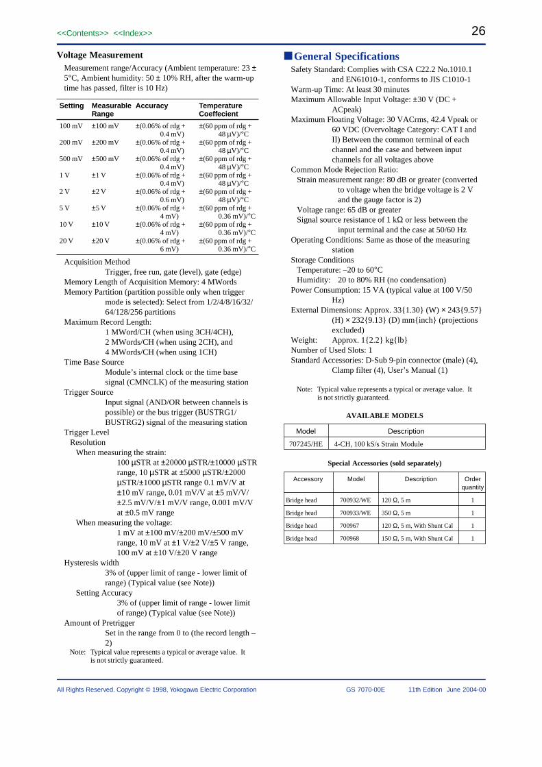
Voltage MeasurementMeasurement range/Accuracy (Ambient temperature: 23 ±5°C, Ambient humidity: 50 ± 10% RH, after the warm-uptime has passed, filter is 10 Hz)
Setting Measurable Accuracy TemperatureRange Coeffecient
100 mV ±100 mV ±(0.06% of rdg + ±(60 ppm of rdg +0.4 mV) 48 µV)/°C
200 mV ±200 mV ±(0.06% of rdg + ±(60 ppm of rdg +0.4 mV) 48 µV)/°C
500 mV ±500 mV ±(0.06% of rdg + ±(60 ppm of rdg +0.4 mV) 48 µV)/°C
1 V ±1 V ±(0.06% of rdg + ±(60 ppm of rdg +0.4 mV) 48 µV)/°C
2 V ±2 V ±(0.06% of rdg + ±(60 ppm of rdg +0.6 mV) 48 µV)/°C
5 V ±5 V ±(0.06% of rdg + ±(60 ppm of rdg +4 mV) 0.36 mV)/°C
10 V ±10 V ±(0.06% of rdg + ±(60 ppm of rdg +4 mV) 0.36 mV)/°C
20 V ±20 V ±(0.06% of rdg + ±(60 ppm of rdg +6 mV) 0.36 mV)/°C
Acquisition MethodTrigger, free run, gate (level), gate (edge)
Memory Length of Acquisition Memory: 4 MWordsMemory Partition (partition possible only when trigger
mode is selected): Select from 1/2/4/8/16/32/64/128/256 partitions
Maximum Record Length:1 MWord/CH (when using 3CH/4CH),2 MWords/CH (when using 2CH), and4 MWords/CH (when using 1CH)
Time Base SourceModule’s internal clock or the time basesignal (CMNCLK) of the measuring station
Trigger SourceInput signal (AND/OR between channels ispossible) or the bus trigger (BUSTRG1/BUSTRG2) signal of the measuring station
Trigger LevelResolution
When measuring the strain:100 µSTR at ±20000 µSTR/±10000 µSTRrange, 10 µSTR at ±5000 µSTR/±2000µSTR/±1000 µSTR range 0.1 mV/V at±10 mV range, 0.01 mV/V at ±5 mV/V/±2.5 mV/V/±1 mV/V range, 0.001 mV/Vat ±0.5 mV range
When measuring the voltage:1 mV at ±100 mV/±200 mV/±500 mVrange, 10 mV at ±1 V/±2 V/±5 V range,100 mV at ±10 V/±20 V range
Hysteresis width3% of (upper limit of range - lower limit ofrange) (Typical value (see Note))
Setting Accuracy3% of (upper limit of range - lower limitof range) (Typical value (see Note))
Amount of PretriggerSet in the range from 0 to (the record length –2)
Note: Typical value represents a typical or average value. Itis not strictly guaranteed.
General SpecificationsSafety Standard: Complies with CSA C22.2 No.1010.1
and EN61010-1, conforms to JIS C1010-1Warm-up Time: At least 30 minutesMaximum Allowable Input Voltage: ±30 V (DC +
ACpeak)Maximum Floating Voltage: 30 VACrms, 42.4 Vpeak or
60 VDC (Overvoltage Category: CAT I andII) Between the common terminal of eachchannel and the case and between inputchannels for all voltages above
Common Mode Rejection Ratio:Strain measurement range: 80 dB or greater (converted
to voltage when the bridge voltage is 2 Vand the gauge factor is 2)
Voltage range: 65 dB or greaterSignal source resistance of 1 kΩ or less between the
input terminal and the case at 50/60 HzOperating Conditions: Same as those of the measuring
stationStorage Conditions
Temperature: –20 to 60°CHumidity: 20 to 80% RH (no condensation)
Power Consumption: 15 VA (typical value at 100 V/50Hz)
External Dimensions: Approx. 331.30 (W) × 2439.57(H) × 2329.13 (D) mminch (projectionsexcluded)
Weight: Approx. 12.2 kglbNumber of Used Slots: 1Standard Accessories: D-Sub 9-pin connector (male) (4),
Clamp filter (4), User’s Manual (1)
Note: Typical value represents a typical or average value. Itis not strictly guaranteed.
AVAILABLE MODELS
Model Description
707245/HE 4-CH, 100 kS/s Strain Module
Special Accessories (sold separately)
Accessory Model Description Orderquantity
Bridge head 700932/WE 120 Ω, 5 m 1
Bridge head 700933/WE 350 Ω, 5 m 1
Bridge head 700967 120 Ω, 5 m, With Shunt Cal 1
Bridge head 700968 150 Ω, 5 m, With Shunt Cal 1

27<<Contents>> <<Index>>
All Rights Reserved. Copyright © 1998, Yokogawa Electric Corporation GS 7070-00E 11th Edition June 2004-00
Accessories (sold separately)
Accessory Model Description Orderquantity
I/O connector (cover) A1618JD D-sub (9 pin) 1
I/O connector (cover) A1520JD D-sub (9 pin) 1
700932/WE700933/WE
700967700968
Dimensions
33
(1.3)
24
2.4
(9
.54
)
227 (8.94) 4.5
(0.18)
START
CH1
INPUTS30 VpkMAX
CH2
CH3
CH4
CAT
4-CH, 100kS/s
Unit: mm (inch)
28
All Rights Reserved. Copyright © 1998, Yokogawa Electric Corporation
<<Contents>> <<Index>>
GS 7070-00E 11th Edition June 2004-00
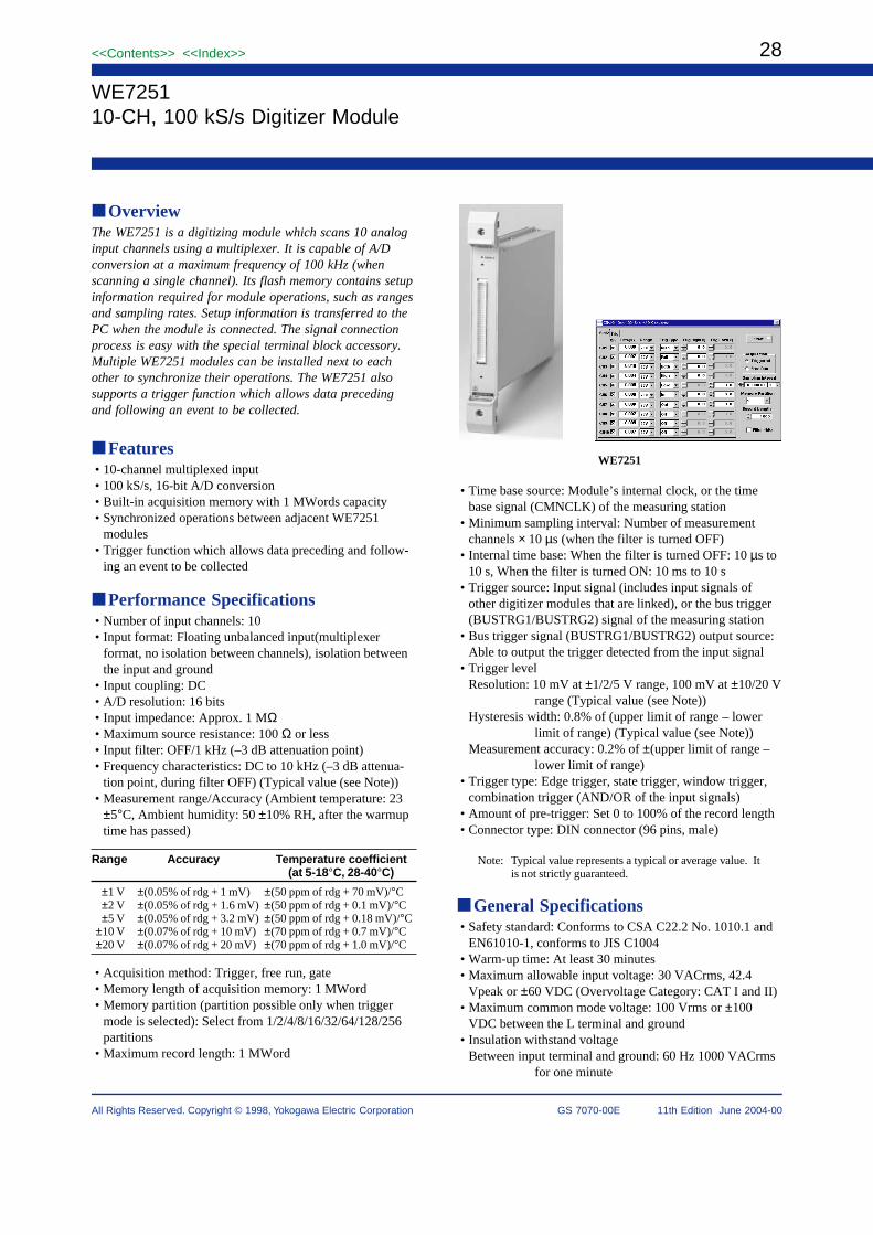
WE725110-CH, 100 kS/s Digitizer Module
OverviewThe WE7251 is a digitizing module which scans 10 analoginput channels using a multiplexer. It is capable of A/Dconversion at a maximum frequency of 100 kHz (whenscanning a single channel). Its flash memory contains setupinformation required for module operations, such as rangesand sampling rates. Setup information is transferred to thePC when the module is connected. The signal connectionprocess is easy with the special terminal block accessory.Multiple WE7251 modules can be installed next to eachother to synchronize their operations. The WE7251 alsosupports a trigger function which allows data precedingand following an event to be collected.
Features• 10-channel multiplexed input• 100 kS/s, 16-bit A/D conversion• Built-in acquisition memory with 1 MWords capacity• Synchronized operations between adjacent WE7251
modules• Trigger function which allows data preceding and follow-
ing an event to be collected
Performance Specifications• Number of input channels: 10• Input format: Floating unbalanced input(multiplexer
format, no isolation between channels), isolation betweenthe input and ground
• Input coupling: DC• A/D resolution: 16 bits• Input impedance: Approx. 1 MΩ• Maximum source resistance: 100 Ω or less• Input filter: OFF/1 kHz (–3 dB attenuation point)• Frequency characteristics: DC to 10 kHz (–3 dB attenua-
tion point, during filter OFF) (Typical value (see Note))• Measurement range/Accuracy (Ambient temperature: 23
±5°C, Ambient humidity: 50 ±10% RH, after the warmuptime has passed)
Range Accuracy Temperature coefficient(at 5-18°C, 28-40°C)
±1 V ±(0.05% of rdg + 1 mV) ±(50 ppm of rdg + 70 mV)/°C±2 V ±(0.05% of rdg + 1.6 mV) ±(50 ppm of rdg + 0.1 mV)/°C±5 V ±(0.05% of rdg + 3.2 mV) ±(50 ppm of rdg + 0.18 mV)/°C
±10 V ±(0.07% of rdg + 10 mV) ±(70 ppm of rdg + 0.7 mV)/°C±20 V ±(0.07% of rdg + 20 mV) ±(70 ppm of rdg + 1.0 mV)/°C
• Acquisition method: Trigger, free run, gate• Memory length of acquisition memory: 1 MWord• Memory partition (partition possible only when trigger
mode is selected): Select from 1/2/4/8/16/32/64/128/256partitions
• Maximum record length: 1 MWord
• Time base source: Module’s internal clock, or the timebase signal (CMNCLK) of the measuring station
• Minimum sampling interval: Number of measurementchannels × 10 µs (when the filter is turned OFF)
• Internal time base: When the filter is turned OFF: 10 µs to10 s, When the filter is turned ON: 10 ms to 10 s
• Trigger source: Input signal (includes input signals ofother digitizer modules that are linked), or the bus trigger(BUSTRG1/BUSTRG2) signal of the measuring station
• Bus trigger signal (BUSTRG1/BUSTRG2) output source:Able to output the trigger detected from the input signal
• Trigger levelResolution: 10 mV at ±1/2/5 V range, 100 mV at ±10/20 V
range (Typical value (see Note))Hysteresis width: 0.8% of (upper limit of range – lower
limit of range) (Typical value (see Note))Measurement accuracy: 0.2% of ±(upper limit of range –
lower limit of range)• Trigger type: Edge trigger, state trigger, window trigger,
combination trigger (AND/OR of the input signals)• Amount of pre-trigger: Set 0 to 100% of the record length• Connector type: DIN connector (96 pins, male)
Note: Typical value represents a typical or average value. Itis not strictly guaranteed.
General Specifications• Safety standard: Conforms to CSA C22.2 No. 1010.1 and
EN61010-1, conforms to JIS C1004• Warm-up time: At least 30 minutes• Maximum allowable input voltage: 30 VACrms, 42.4
Vpeak or ±60 VDC (Overvoltage Category: CAT I and II)• Maximum common mode voltage: 100 Vrms or ±100
VDC between the L terminal and ground• Insulation withstand voltage
Between input terminal and ground: 60 Hz 1000 VACrmsfor one minute
WE7251
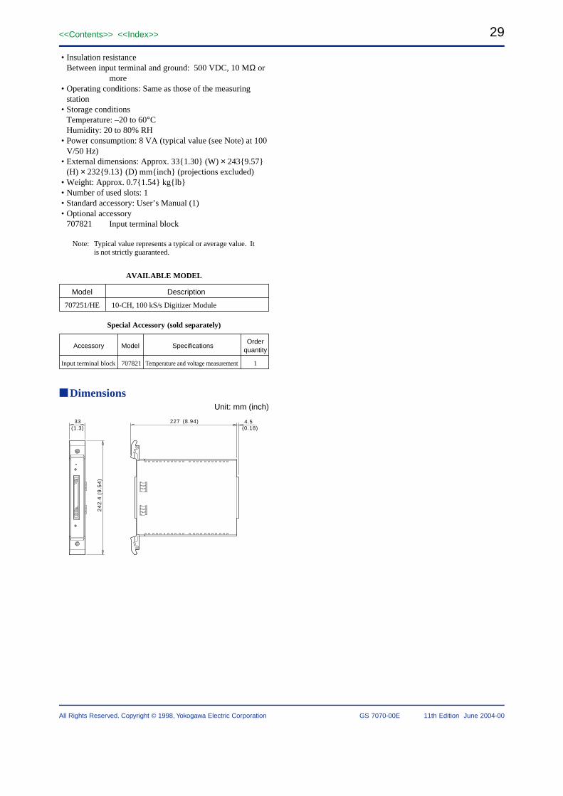
29<<Contents>> <<Index>>
All Rights Reserved. Copyright © 1998, Yokogawa Electric Corporation GS 7070-00E 11th Edition June 2004-00
• Insulation resistanceBetween input terminal and ground: 500 VDC, 10 MΩ or
more• Operating conditions: Same as those of the measuring
station• Storage conditions
Temperature: –20 to 60°CHumidity: 20 to 80% RH
• Power consumption: 8 VA (typical value (see Note) at 100V/50 Hz)
• External dimensions: Approx. 331.30 (W) × 2439.57(H) × 2329.13 (D) mminch (projections excluded)
• Weight: Approx. 0.71.54 kglb• Number of used slots: 1• Standard accessory: User’s Manual (1)• Optional accessory
707821 Input terminal block
Note: Typical value represents a typical or average value. Itis not strictly guaranteed.
AVAILABLE MODEL
Model Description
707251/HE 10-CH, 100 kS/s Digitizer Module
Special Accessory (sold separately)
Accessory Model SpecificationsOrder
quantity
Input terminal block 707821 Temperature and voltage measurement 1
DimensionsUnit: mm (inch)
4.533(1.3)
24
2.4
(9.5
4)
227 (8.94)(0.18)

30
All Rights Reserved. Copyright © 1998, Yokogawa Electric Corporation
<<Contents>> <<Index>>
GS 7070-00E 11th Edition June 2004-00
WE7262
WE726232-Bit Digital I/O Module
OverviewThe WE7262 32-bit digital I/O module is used to input oroutput TTL/CMOS-level digital signals.
The module contains in its flash memory the graphic datafor screens used to set such data items as the I/O setpointsnecessary for module operation. When connected to apersonal computer, the module is actuated once it transfersthe graphic data to the computer. In addition, the moduleis provided with a 2-channel pulse counter. An optional 16-bit I/O terminal box can be connected to the module toenable the module to handle contact I/O signals.
Features• 32-bit non-isolated bi-directional digital I/Os• Continuous measurement• 2-channel counter function• 2MHz maximum input frequency in the counter block• Detection of input-pattern matches on an 8-bit basis
Performance SpecificationsInput/Output Section
Number of input/output points: 32 pointsMaximum output current: ±3.2 mAOutput voltage
H level @–3.2 mA: 3.8 V minL level @3.2 mA: 0.5 V max
Input voltageH level: 2.0 V minL level: 0.6 V max
Maximum allowable input voltage: –3 V to +8 V (Over-voltage Category: CAT I and II)
Sampling interval during continuous measurement of inputpattern: 10 ms to 10 s
Output impedance Approx. 100 ΩInput impedance: Approx. 47 kΩInput format: Non-isolated unbalancedConnector type: D-sub type 25 pins (female)Pattern match detection (see Note 1)
Detection bit: Compares every 8 bits of input, generatesup to 4 interrupts
Chattering elimination: ON/OFF selectable. When turnedON, eliminates bouncing of frequencies lessthan or equal to 1 ms
When four or more WE7262 or WE7141 modules are putinto operation for continuous measurement, the samplinginterval of each module must be set to no shorter than 20 ms.
Counter SectionNumber of input channels: 2External input frequency: 2 MHz maxMinimum input pulse width: 100 nsInput voltage
H level: 2.0 V minL level: 0.4 V max
Maximum allowable input voltage: –3 V to +8 V (Over-voltage category: CAT I and II)
Input impedance: Approx. 47 kΩInput format: Non-isolated unbalancedMaximum number of counts: FFFE0000H (4294836224)Overflow detection
Counter overflow detectableControl (Count enable)
• Manual gate• Internal gate: Control with the timer
- Selectable range: 1 ms to 600 s- Resolution: 0.1 ms- Setting accuracy (see Note 2): ±(0.02% of setting +
1 µs)• External gate: Control with external signal, H active,
common to both input channels- Number of inputs: 1- Input pulse width: 1 ms or more
Note 1: Not supported by the WE7000 Control Software.Note 2: Measurement value obtained under standard
operating conditions.
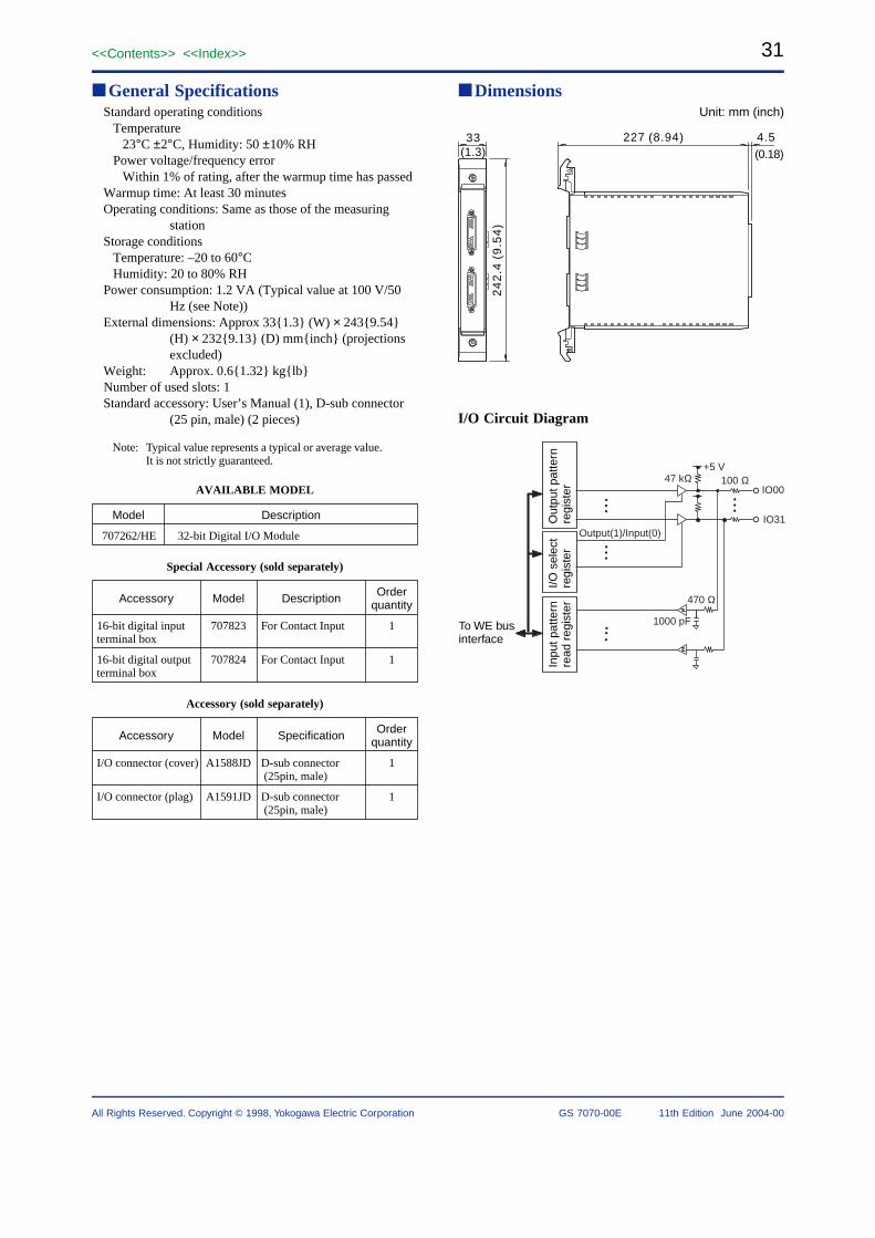
31<<Contents>> <<Index>>
All Rights Reserved. Copyright © 1998, Yokogawa Electric Corporation GS 7070-00E 11th Edition June 2004-00
General SpecificationsStandard operating conditions
Temperature23°C ±2°C, Humidity: 50 ±10% RH
Power voltage/frequency errorWithin 1% of rating, after the warmup time has passed
Warmup time: At least 30 minutesOperating conditions: Same as those of the measuring
stationStorage conditions
Temperature: –20 to 60°CHumidity: 20 to 80% RH
Power consumption: 1.2 VA (Typical value at 100 V/50Hz (see Note))
External dimensions: Approx 331.3 (W) × 2439.54(H) × 2329.13 (D) mminch (projectionsexcluded)
Weight: Approx. 0.61.32 kglbNumber of used slots: 1Standard accessory: User’s Manual (1), D-sub connector
(25 pin, male) (2 pieces)
Note: Typical value represents a typical or average value.It is not strictly guaranteed.
AVAILABLE MODEL
707262/HE 32-bit Digital I/O Module
Model Description
Special Accessory (sold separately)
Accessory Model Description Order quantity
16-bit digital input terminal box
707823 1For Contact Input
16-bit digital output terminal box
707824 1For Contact Input
Accessory (sold separately)
Accessory Model Specification Order quantity
I/O connector (cover) A1588JD 1D-sub connector (25pin, male)
I/O connector (plag) A1591JD 1D-sub connector (25pin, male)
DimensionsUnit: mm (inch)
33(1.3)
24
2.4
(9
.54
)
227 (8.94) 4.5(0.18)
I/O Circuit Diagram
47 kΩ
470 Ω
1000 pF
100 Ω
Output(1)/Input(0)
IO00
IO31
+5 V
To WE bus interface
Out
put p
atte
rn
regi
ster
I/O s
elec
t re
gist
erIn
put p
atte
rn
read
reg
iste
r

32
All Rights Reserved. Copyright © 1998, Yokogawa Electric Corporation
<<Contents>> <<Index>>
GS 7070-00E 11th Edition June 2004-00
WE7271/WE7272
WE7271/WE72724-CH, 100 kS/s Isolated Digitizer Module
OverviewThe WE7271/WE7272 4-channel 100-kS/s isolated digitizermodule can convert 4 channels’ worth of analog signals todigital signals at a maximum speed of 100 kHz. Equipped withfour A/D converters, each module can sample data throughfour channels simultaneously at 100 kHz. The input channelsare isolated from each other, as well as from the ground.
Each module contains in its flash memory the graphic datafor screens used to set such data items as the range andsampling rate necessary for module operation. Whenconnected to a personal computer, the module is actuatedonce it transfers the graphic data to the computer. Inaddition, two or more modules can be mounted side by sideto enable synchronous operation. These modules supportthe trigger function that permits you to acquire data beforeand after the rise of a specific event.
Features• 100-kS/s sampling and 16-bit analog-to-digital conversion
on all four channels simultaneously• Isolation between inputs and between inputs and ground• Built-in 4MWord acquisition memory• Operates in sync with an adjacent WE7271/WE7272
module• Trigger function that allows data immediately before and
after the rise of an event, to be acquired correctly• Input connector
WE7271: Clamp type terminalWE7272: BNC
Performance SpecificationsNumber of input channels: 4Input format: Floating unbalanced input, isolation between
channels and between the input and groundA/D resolution: 16 bitsInput impedance: Approx. 1 MΩInput coupling: DCMaximum source resistance: 100 Ω or belowInput filter: OFF/5 kHz/500 Hz (typical value (see Note 1)
at –3 dB attenuation point)Frequency characteristics: DC to 40 kHz (typical value
(see Note 1) at –1.5 dB attenuation point, withfilter turned off)
Measurement range/Accuracy (see Note 2) (see Note 3)
Range Accuracy (see Note 2) Temperature coefficient(see Note 3)
±1 V ±(0.04% of rdg + 0.4 mV) ±(40 ppm of rdg + 22 µV)/°C±2 V ±(0.04% of rdg + 0.6 mV) ±(40 ppm of rdg + 32 µV)/°C±5 V ±(0.04% of rdg + 1.3 mV) ±(40 ppm of rdg + 60 µV)/°C±10 V ±(0.07% of rdg + 6.5 mV) ±(65 ppm of rdg + 460 µV)/°C±20 V ±(0.07% of rdg + 8.7 mV) ±(65 ppm of rdg + 560 µV)/°C±35 V ±(0.07% of rdg + 15.5 mV) ±(65 ppm of rdg + 840 µV)/°C
Acquisition method: Trigger, free run, gate (level), gate(edge)
Memory length of acquisition memory: 4 MWordsMemory partition (possible only when trigger mode is
selected): Select from 1/2/4/8/16/32/64/128/256 partitions
Maximum record length: 1 MWord/CH (for 3 CH/4 CHmeasurement), 2 MWords/CH (for 2 CHmeasurement), 4 MWords/CH (for 1 CHmeasurement)
Time base source: Module’s internal clock, or the timebase signal (CMNCLK) of the measuringstation (WE bus)
Sampling interval: 10 µs to 10 s, 1 ms to 10 s (when in freerun mode using WE7000 control software)
Trigger source: Input signal (includes input signals ofother isolated digitizer modules that arelinked), or the bus trigger (BUSTRG1/BUSTRG2) signal of the measuring station
Bus trigger signal (BUSTRG1/BUSTRG2) output source:Able to output the trigger detected from theinput signal
Trigger levelResolution: 10 mV at ±1/2/5 V range, 100 mV at ±10/20/
35 V range (Typical value (see Note 1))Hysteresis width: 0.5% of (upper limit of range – lower
limit of range) (Typical value (see Note 1))Measurement accuracy: 0.5% of ((upper limit of range –
lower limit of range)Trigger type: Edge trigger, state trigger, combination
trigger (AND/OR of the input signals)Amount of pre-trigger: Set in the range from 0 to the
record length – 2

33<<Contents>> <<Index>>
All Rights Reserved. Copyright © 1998, Yokogawa Electric Corporation GS 7070-00E 11th Edition June 2004-00
Connector type:WE7271: Clamp type terminal (detachable terminal
block)Recommended stripped length of inputsignal cable: 7 mmThickness of input signal cable: 0.5 to 1.5mm2 (for twisted cable)
WE7272: Isolated BNCSampling skew between channels in synchronous
operation (with filter turned off):Channels in one module: Approx. 30 ns (Typical value
(see Note 1))Channels in adjacent modules: 20 × (N – 1) + 50 ns
(Typical value (see Note 1) + module skew),where N is the number of linked modules.
General SpecificationsSafety standard: Complies with CSA C22.2 No. 1010.1
and EN61010-1, conforms to JIS C1010-1Warm-up time: At least 30 minutesMaximum allowable input voltage: ±50 VDC + AC peak
(Overvoltage Category: CAT I and II)Maximum common mode voltage
Between the L terminal and groundWE7271: 250 VACrms or ±250 VDCWE7272: ±42.4 VDC + AC peak
Maximum voltage across channelsWE7271: 250 VACrms or ±250 VDC (Between any
two terminals of different channels)WE7272: ±42.4 VDC + AC peak (Between L
terminals of different channels)Withstanding voltage
Between input terminal and ground: 60 Hz 1500VACrms for one minute
Between channelsWE7271: 60 Hz 2300 VACrms for one minuteWE7272: 60 Hz 1500 VACrms for one minute
Insulation resistanceBetween input terminal and ground and between
channels: 500 VDC, 10 MΩ or higherOperating conditions: Same as those of the measuring
stationStorage conditions
Temperature: –20°C to 60°CHumidity: 20 to 80% RH (no condensation)
Power consumption: 12 VA (Typical value (see Note 1) at100 V/50 Hz)
External dimensions: Approx. 331.3 (W) × 2439.54(H) × 2329.13 (D) mminch (projectionsexcluded)
Weight: Approx. 0.71.54 kglbNumber of used slots: 1Standard accessory
WE7271: Terminal block (1) (attached to the inputconnector at the time of shipment), User’sManual (1)
WE7272: User’s Manual (1)
Note 1: Typical value represents a typical or average value.It is not strictly guaranteed.
Note 2: Ambient temperature: 23 ±5°C, Ambient humidity:50 ±10% RH, after the warmup time has passed
Note 3: At 5°C - 18°C or 28°C - 40°CAVAILABLE MODEL
707271/HE 4-CH, 100 kS/s Isolated Digitizer Module
707272/HE 4-CH, 100 kS/s Isolated Digitizer Module
Model Description
Accessory (sold separately)
Accessory Model Description Order quantity
Terminal block A1460JT 116-point Terminal
DimensionsWE7271
Unit: mm (inch)
33(1.3)
24
2.4
(9
.54
)
227 (8.94) 4.5
(0.18)
SAMPLE
4CH 100kS/s
WE7272Unit: mm (inch)
33(1.3)
24
2.4
(9
.54
)
227 (8.94) 4.5(0.18)
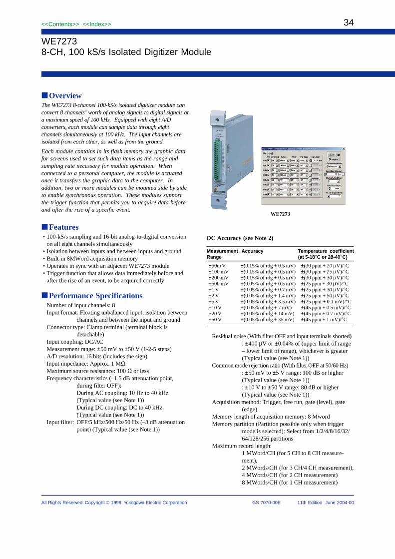
34
All Rights Reserved. Copyright © 1998, Yokogawa Electric Corporation
<<Contents>> <<Index>>
GS 7070-00E 11th Edition June 2004-00
WE7273
WE72738-CH, 100 kS/s Isolated Digitizer Module
OverviewThe WE7273 8-channel 100-kS/s isolated digitizer module canconvert 8 channels’ worth of analog signals to digital signals ata maximum speed of 100 kHz. Equipped with eight A/Dconverters, each module can sample data through eightchannels simultaneously at 100 kHz. The input channels areisolated from each other, as well as from the ground.
Each module contains in its flash memory the graphic datafor screens used to set such data items as the range andsampling rate necessary for module operation. Whenconnected to a personal computer, the module is actuatedonce it transfers the graphic data to the computer. Inaddition, two or more modules can be mounted side by sideto enable synchronous operation. These modules supportthe trigger function that permits you to acquire data beforeand after the rise of a specific event.
Features• 100-kS/s sampling and 16-bit analog-to-digital conversion
on all eight channels simultaneously• Isolation between inputs and between inputs and ground• Built-in 8MWord acquisition memory• Operates in sync with an adjacent WE7273 module• Trigger function that allows data immediately before and
after the rise of an event, to be acquired correctly
Performance SpecificationsNumber of input channels: 8Input format: Floating unbalanced input, isolation between
channels and between the input and groundConnector type: Clamp terminal (terminal block is
detachable)Input coupling: DC/ACMeasurement range: ±50 mV to ±50 V (1-2-5 steps)A/D resolution: 16 bits (includes the sign)Input impedance: Approx. 1 MΩMaximum source resistance: 100 Ω or lessFrequency characteristics (–1.5 dB attenuation point,
during filter OFF):During AC coupling: 10 Hz to 40 kHz(Typical value (see Note 1))During DC coupling: DC to 40 kHz(Typical value (see Note 1))
Input filter: OFF/5 kHz/500 Hz/50 Hz (–3 dB attenuationpoint) (Typical value (see Note 1))
DC Accuracy (see Note 2)
Measurement Accuracy Temperature coefficientRange (at 5-18°C or 28-40°C)
±50m V ±(0.15% of rdg + 0.5 mV) ±(30 ppm + 20 µV)/°C±100 mV ±(0.15% of rdg + 0.5 mV) ±(30 ppm + 25 µV)/°C±200 mV ±(0.15% of rdg + 0.5 mV) ±(30 ppm + 30 µV)/°C±500 mV ±(0.05% of rdg + 0.5 mV) ±(25 ppm + 30 µV)/°C±1 V ±(0.05% of rdg + 0.7 mV) ±(25 ppm + 30 µV)/°C±2 V ±(0.05% of rdg + 1.4 mV) ±(25 ppm + 50 µV)/°C±5 V ±(0.05% of rdg + 3.5 mV) ±(25 ppm + 0.1 mV)/°C±10 V ±(0.05% of rdg + 7 mV) ±(45 ppm + 0.5 mV)/°C±20 V ±(0.05% of rdg + 14 mV) ±(45 ppm + 0.7 mV)/°C±50 V ±(0.05% of rdg + 35 mV) ±(45 ppm + 1 mV)/°C
Residual noise (With filter OFF and input terminals shorted): ±400 µV or ±0.04% of (upper limit of range– lower limit of range), whichever is greater(Typical value (see Note 1))
Common mode rejection ratio (With filter OFF at 50/60 Hz): ±50 mV to ±5 V range: 100 dB or higher(Typical value (see Note 1)): ±10 V to ±50 V range: 80 dB or higher(Typical value (see Note 1))
Acquisition method: Trigger, free run, gate (level), gate(edge)
Memory length of acquisition memory: 8 MwordMemory partition (Partition possible only when trigger
mode is selected): Select from 1/2/4/8/16/32/64/128/256 partitions
Maximum record length:1 MWord/CH (for 5 CH to 8 CH measure-ment),2 MWords/CH (for 3 CH/4 CH measurement),4 MWords/CH (for 2 CH measurement)8 MWords/CH (for 1 CH measurement)
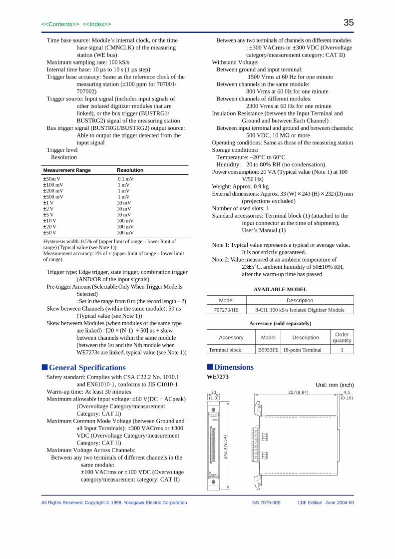
35<<Contents>> <<Index>>
All Rights Reserved. Copyright © 1998, Yokogawa Electric Corporation GS 7070-00E 11th Edition June 2004-00
Time base source: Module’s internal clock, or the timebase signal (CMNCLK) of the measuringstation (WE bus)
Maximum sampling rate: 100 kS/sInternal time base: 10 µs to 10 s (1 µs step)Trigger base accuracy: Same as the reference clock of the
measuring station (±100 ppm for 707001/707002)
Trigger source: Input signal (includes input signals ofother isolated digitizer modules that arelinked), or the bus trigger (BUSTRG1/BUSTRG2) signal of the measuring station
Bus trigger signal (BUSTRG1/BUSTRG2) output source:Able to output the trigger detected from theinput signal
Trigger levelResolution
Measurement Range Resolution
±50m V 0.1 mV±100 mV 1 mV±200 mV 1 mV±500 mV 1 mV±1 V 10 mV±2 V 10 mV±5 V 10 mV±10 V 100 mV±20 V 100 mV±50 V 100 mV
Hysteresis width: 0.5% of (upper limit of range – lower limit ofrange) (Typical value (see Note 1))Measurement accuracy: 1% of ± (upper limit of range – lower limitof range)
Trigger type: Edge trigger, state trigger, combination trigger(AND/OR of the input signals)
Pre-trigger Amount (Selectable Only When Trigger Mode IsSelected): Set in the range from 0 to (the record length – 2)
Skew between Channels (within the same module): 50 ns(Typical value (see Note 1))
Skew betweem Modules (when modules of the same typeare linked) : [20 × (N-1) + 50] ns + skewbetween channels within the same module(between the 1st and the Nth module whenWE7273s are linked, typical value (see Note 1))
General SpecificationsSafety standard: Complies with CSA C22.2 No. 1010.1
and EN61010-1, conforms to JIS C1010-1Warm-up time: At least 30 minutesMaximum allowable input voltage: ±60 V(DC + ACpeak)
(Overvoltage Category/measurementCategory: CAT II)
Maximum Common Mode Voltage (between Ground andall Input Terminals): ±300 VACrms or ±300VDC (Overvoltage Category/measurementCategory: CAT II)
Maximum Voltage Across Channels:Between any two terminals of different channels in the
same module:±100 VACrms or ±100 VDC (Overvoltagecategory/measurement category: CAT II)
Between any two terminals of channels on different modules: ±300 VACrms or ±300 VDC (Overvoltagecategory/measurement category: CAT II)
Withstand Voltage:Between ground and input terminal:
1500 Vrms at 60 Hz for one minuteBetween channels in the same module:
800 Vrms at 60 Hz for one minuteBetween channels of different modules:
2300 Vrms at 60 Hz for one minuteInsulation Resistance (between the Input Terminal and
Ground and between Each Channel) :Between input terminal and ground and between channels:
500 VDC, 10 MΩ or moreOperating conditions: Same as those of the measuring stationStorage conditions:
Temperature: –20°C to 60°CHumidity: 20 to 80% RH (no condensation)
Power consumption: 20 VA (Typical value (Note 1) at 100V/50 Hz)
Weight: Approx. 0.9 kgExternal dimensions: Approx. 33 (W) × 243 (H) × 232 (D) mm
(projections excluded)Number of used slots: 1Standard accessories: Terminal block (1) (attached to the
input connector at the time of shipment),User’s Manual (1)
Note 1: Typical value represents a typical or average value.It is not strictly guaranteed.
Note 2: Value measured at an ambient temperature of23±5°C, ambient humidity of 50±10% RH,after the warm-up time has passed
AVAILABLE MODEL
8-CH, 100 kS/s Isolated Digitizer Module
Model
707273/HE
Description
Accessory (sold separately)
Accessory Model Description Order quantity
Terminal block B9953FE 118-point Terminal
DimensionsWE7273
Unit: mm (inch)33
(1.3)
24
2.4
(9.5
4)
227(8.94) 4.5(0.18)

36
All Rights Reserved. Copyright © 1998, Yokogawa Electric Corporation
<<Contents>> <<Index>>
GS 7070-00E 11th Edition June 2004-00
WE72752-CH, 1 MS/s Isolated Digitizer Module
OverviewThe WE7275 2-channel 1 MS/s isolated digitizer modulecan convert the analog signals of 2 channels to digitalsignals at a maximum speed of 1 MHz. Equipped with twoA/D converters, the module can sample data through twochannels simultaneously at 1 MHz. The input channels areisolated from each other, as well as from the ground.
The module contains in its flash memory the graphic datafor screens used to set such data items as the range andsampling rate necessary for module operation. Whenconnected to a personal computer, the module is actuatedonce it transfers the graphic data to the computer. Inaddition, two or more modules can be mounted side by sideto enable synchronous operation. The module supports thetrigger function that permits you to acquire data before andafter the rise of a specific event.
Features• 1 MS/s sampling and 14-bit analog-to-digital conversion of
both channels simultaneously• Isolation between input channels and between input
channels and ground• Built-in 4MWord acquisition memory• Operates in sync with an adjacent WE7275 module• Trigger function that allows data immediately before and
after the rise of an event, to be acquired correctly
Performance SpecificationsNumber of input channels: 2Input format: Floating unbalanced input, isolation between
channels and between the input and groundConnector type: Isolated BNCInput coupling: DC/ACA/D resolution:
±100 mV to ±200 V range: Equivalent to 14 bits(includes the sign)
±350 V range: Equivalent to 13 bits (includes the sign)Input impedance: Approx. 1 MΩMaximum source resistance: 100 V or lessFrequency characteristics (–3 dB attenuation point, whenfilter is turned OFF):
For DC coupling: DC to 500 kHz (Typical value (seeNote))
For AC coupling: 1 Hz to 500 kHz (Typical value (seeNote))
WE7275
Measurement range/Accuracy (Ambient temperature: 23±5°C,
Ambient humidity: 50 ±10% RH, after the warm-up timehas passed)
Range Accuracy Temperature coefficient(at 5-18°C or 28-40°C)
±100 mV ±(0.15% of rdg + 0.4 mV) ±(100 ppm of rdg + 30 µV)/°C±200 mV ±(0.15% of rdg + 0.6 mV) ±(100 ppm of rdg + 40 µV)/°C±500 mV ±(0.15% of rdg + 1 mV) ±(100 ppm of rdg + 60 µV)/°C±1 V ±(0.15% of rdg + 1.7 mV) ±(100 ppm of rdg + 0.1 mV)/°C±2 V ±(0.15% of rdg + 3.2 mV) ±(100 ppm of rdg + 0.2 mV)/°C±5 V ±(0.15% of rdg + 8 mV) ±(100 ppm of rdg + 0.5 mV)/°C±10 V ±(0.15% of rdg + 40 mV) ±(100 ppm of rdg + 3 mV)/°C±20 V ±(0.15% of rdg + 60 mV) ±(100 ppm of rdg + 4 mV)/°C±50 V ±(0.15% of rdg + 100 mV) ±(100 ppm of rdg + 6 mV)/°C±100 V ±(0.15% of rdg + 170 mV) ±(100 ppm of rdg + 10 mV)/°C±200 V ±(0.15% of rdg + 320 mV) ±(100 ppm of rdg + 20 mV)/°C±350 V ±(0.15% of rdg + 800 mV) ±(100 ppm of rdg + 50 mV)/°C
Input filter:Low-pass filter
Cut-off frequency: OFF, 100 kHz, 40 kHz, 4 kHz, 400Hz (Typical value (see Note))
Filter characteristics: 4th order Bessel characteristics(–24 dB/oct.)
Anti-aliasing filterCut-off frequency: OFF, 20 Hz to 40 kHz (in steps of
1, 2, 4 and their ten-fold multiples)Pass-band characteristics: ±1 dB at 5 to 100% of the
cut-off frequency (Typical value (seeNote))
Attenuation characteristics: –80 dB at frequenciesgreater than or equal to 2.1 times the cut-off frequency (Typical value (see Note))
Acquisition method: Trigger, free run, gate (level), gate(edge)
Memory length of acquisition memory:2 MWord/CH (when using 2CH) or 4 MWord/CH (when using 1CH)

37<<Contents>> <<Index>>
All Rights Reserved. Copyright © 1998, Yokogawa Electric Corporation GS 7070-00E 11th Edition June 2004-00
Memory partition (partition possible only when triggermode is selected): Select from 1/2/4/8/16/32/64/128/256
partitionsMaximum sampling rate: 1.024 MS/sTime base source: Module’s internal clock, external clock,
or the time base signal (CMNCLK) of themeasuring station (WE bus)
Internal time base: 1 µs to 1 sTrigger source: Input signal (includes input signals of
other isolated digitizer modules that arelinked), or the bus trigger (BUSTRG1/BUSTRG1) signal of the measuring station
Bus trigger signal (BUSTRG1/BUSTRG2) output source:Able to output the trigger detected from theinput signal
Trigger level:Resolution: 1 mV at ±100/200/500 mV range, 10 mV at
±1/2/5 V range, 0.1 V at ±10/20/50 V range,1 V at ±100/200/350 V range
Hysteresis width: 5% of (upper limit of range – lowerlimit of range) (Typical value (see Note))
Setting Accuracy: 3% of ±(upper limit of range – lowerlimit of range)
Trigger type:Edge trigger, state trigger, combinationtrigger (AND/OR of the input signals)
Amount of pre-trigger (selectable only when trigger modeis selected): Set in the range from 0 to (the record length –
2)External clock input:
Input format: Non-isolated unbalanced (TTL)H level input: 2.2 V min.L level input: 0.5 V max.Input resistance: 10 kΩ (Typical value (see Note))Connector type: BNC
Note: Typical value represents a typical or average value. Itis not strictly guaranteed.
General SpecificationsSafety standard: Complies with CSA C22.2 No. 1010.1
and EN61010-1, conforms to JIS C1010-1Warm-up time: At least 30 minutesMaximum allowable input voltage:
Analog input signal: ±400 V (DC + ACpeak)External clock input: –1 V to +6 V(Overvoltage Category: CAT I and II)
Maximum common mode voltage (between the analogsignal input L terminal and ground): ±250 VDC or 250
VACrms (when using the isolated BNC plugincluded in the package)
Maximum voltage across channels (between any twoanalog signal L terminals of different channels):
±250 VDC or 250 VACrmsInsulation withstand voltage:
Between analog signal input L terminal and ground1500 VAC (60 Hz) for one minute
Between analog signal input channel L terminals2300 VAC (60 Hz) for one minute
Insulation resistance (Between analog signal input Lterminal and ground and between analog input channels):
500 VDC, 10 MΩ or more
Operating conditions: Same as those of the measuringstation
Storage conditions:Temperature: –20 to 60°CHumidity: 20 to 80% RH (no condensation)
Power consumption: 14 VA (typical value (see Note) at100 V/50 Hz)
External dimensions: Approx. 331.3 (W) × 2439.54(H) × 2329.13 (D) mminch (projectionsexcluded)
Weight: Approx. 0.81.76 kglbNumber of used slots: 1Standard accessories: Isolated BNC plugs (2), User’s
Manual (1)
Note: Typical value represents a typical or average value. Itis not strictly guaranteed.
AVAILABLE MODELS
Model Description
707275/HE 2-CH, 1 MS/s Isolated Digitizer Module
Accessories (sold separately)
Accessory Model Description Order quantity
Isolated BNC plug A1226JA 1
DimensionsUnit: mm (inch)
33(1.3)
24
2.4
(9
.54
)
227 (8.94) 4.5(0.18)
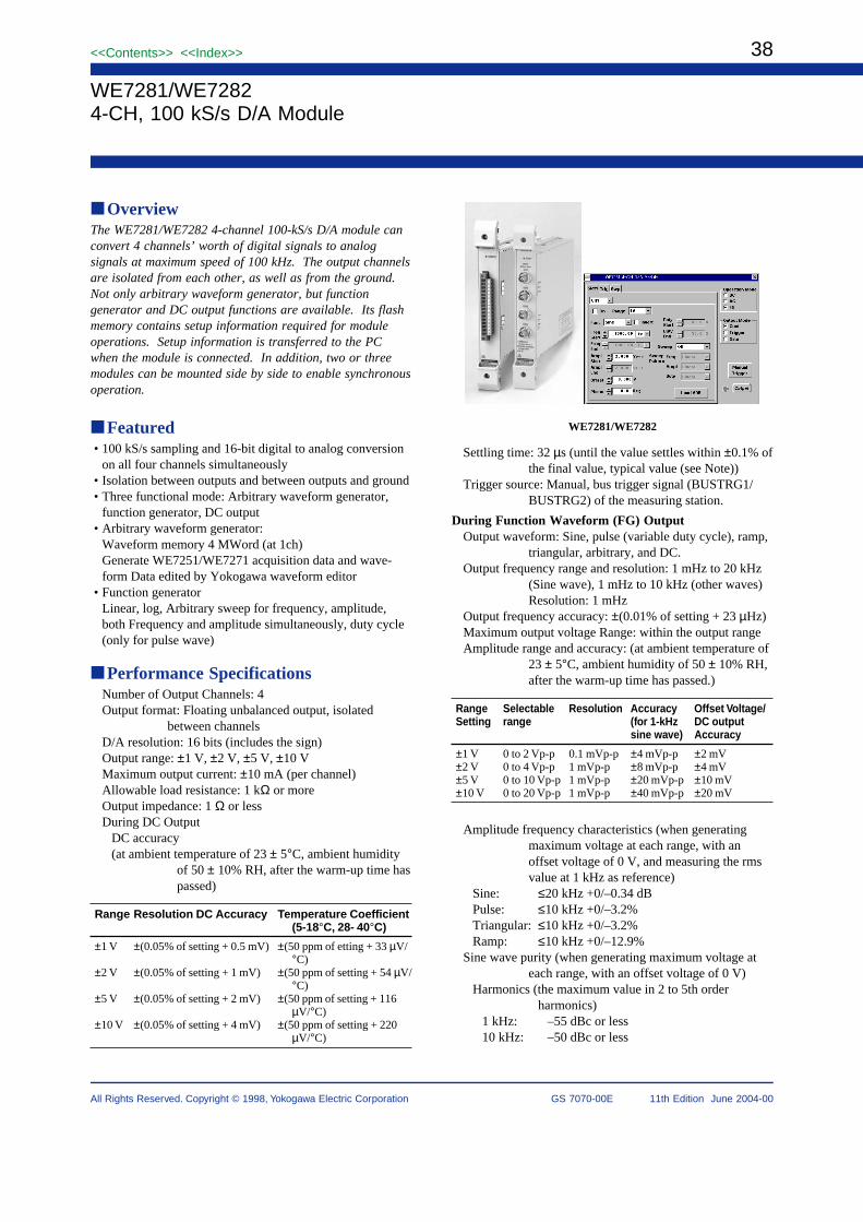
38
All Rights Reserved. Copyright © 1998, Yokogawa Electric Corporation
<<Contents>> <<Index>>
GS 7070-00E 11th Edition June 2004-00
WE7281/WE72824-CH, 100 kS/s D/A Module
OverviewThe WE7281/WE7282 4-channel 100-kS/s D/A module canconvert 4 channels’ worth of digital signals to analogsignals at maximum speed of 100 kHz. The output channelsare isolated from each other, as well as from the ground.Not only arbitrary waveform generator, but functiongenerator and DC output functions are available. Its flashmemory contains setup information required for moduleoperations. Setup information is transferred to the PCwhen the module is connected. In addition, two or threemodules can be mounted side by side to enable synchronousoperation.
Featured• 100 kS/s sampling and 16-bit digital to analog conversion
on all four channels simultaneously• Isolation between outputs and between outputs and ground• Three functional mode: Arbitrary waveform generator,
function generator, DC output• Arbitrary waveform generator:
Waveform memory 4 MWord (at 1ch)Generate WE7251/WE7271 acquisition data and wave-form Data edited by Yokogawa waveform editor
• Function generatorLinear, log, Arbitrary sweep for frequency, amplitude,both Frequency and amplitude simultaneously, duty cycle(only for pulse wave)
Performance SpecificationsNumber of Output Channels: 4Output format: Floating unbalanced output, isolated
between channelsD/A resolution: 16 bits (includes the sign)Output range: ±1 V, ±2 V, ±5 V, ±10 VMaximum output current: ±10 mA (per channel)Allowable load resistance: 1 kΩ or moreOutput impedance: 1 Ω or lessDuring DC Output
DC accuracy(at ambient temperature of 23 ± 5°C, ambient humidity
of 50 ± 10% RH, after the warm-up time haspassed)
Range Resolution DC Accuracy Temperature Coefficient(5-18°C, 28- 40°C)
±1 V ±(0.05% of setting + 0.5 mV) ±(50 ppm of etting + 33 µV/°C)
±2 V ±(0.05% of setting + 1 mV) ±(50 ppm of setting + 54 µV/°C)
±5 V ±(0.05% of setting + 2 mV) ±(50 ppm of setting + 116µV/°C)
±10 V ±(0.05% of setting + 4 mV) ±(50 ppm of setting + 220µV/°C)
Settling time: 32 µs (until the value settles within ±0.1% ofthe final value, typical value (see Note))
Trigger source: Manual, bus trigger signal (BUSTRG1/BUSTRG2) of the measuring station.
During Function Waveform (FG) OutputOutput waveform: Sine, pulse (variable duty cycle), ramp,
triangular, arbitrary, and DC.Output frequency range and resolution: 1 mHz to 20 kHz
(Sine wave), 1 mHz to 10 kHz (other waves)Resolution: 1 mHz
Output frequency accuracy: ±(0.01% of setting + 23 µHz)Maximum output voltage Range: within the output rangeAmplitude range and accuracy: (at ambient temperature of
23 ± 5°C, ambient humidity of 50 ± 10% RH,after the warm-up time has passed.)
Range Selectable Resolution Accuracy Offset Voltage/Setting range (for 1-kHz DC output
sine wave) Accuracy
±1 V 0 to 2 Vp-p 0.1 mVp-p ±4 mVp-p ±2 mV±2 V 0 to 4 Vp-p 1 mVp-p ±8 mVp-p ±4 mV±5 V 0 to 10 Vp-p 1 mVp-p ±20 mVp-p ±10 mV±10 V 0 to 20 Vp-p 1 mVp-p ±40 mVp-p ±20 mV
Amplitude frequency characteristics (when generatingmaximum voltage at each range, with anoffset voltage of 0 V, and measuring the rmsvalue at 1 kHz as reference)
Sine: ≤20 kHz +0/–0.34 dBPulse: ≤10 kHz +0/–3.2%Triangular: ≤10 kHz +0/–3.2%Ramp: ≤10 kHz +0/–12.9%
Sine wave purity (when generating maximum voltage ateach range, with an offset voltage of 0 V)
Harmonics (the maximum value in 2 to 5th orderharmonics)
1 kHz: –55 dBc or less10 kHz: –50 dBc or less
WE7281/WE7282

39<<Contents>> <<Index>>
All Rights Reserved. Copyright © 1998, Yokogawa Electric Corporation GS 7070-00E 11th Edition June 2004-00
Suprious (frequency range of 1 kHz to 100 kHz)1 kHz: –55 dBc or less10 kHz: –50 dBc or less
Pulse wave characteristics (when generating maximumvoltage at each range, with an offset voltage of0 V)
Rise time: 1.2 µs (10% to 90%, typical value (seeNote))
Overshoot: Less than or equal to ±0.5% of the output p-p value (typical value (see Note))
Output jitter: ±5 µsDuty cycle setting
Range: 0 to 100% (resolution 0.1%)Time accuracy: ±((0.01% of 1/the output frequency) +
5 µs)Phase
Target: Start and stop phase of trigger oscillation,gate oscillation, and continuous oscillation
Range: ±360° (Resolution: 0.1°)Output operation: Continuous, trigger, and gateTrigger source: Manual, bus trigger signal (BUSTRG1/
BUSTRG2) of the measuring station.Gate source: Manual, bus trigger signal (BUSTRG1/
BUSTRG2) of the measuring station.Sweep function: Frequency, amplitude, both frequency and
amplitude simultaneously, duty cycle (only forpulse wave)
Sweep mode: Linear, log, and arbitrary patternSweep time:1 s to 1000 sSweep time resolution: 1 msSweep time accuracy: ±(0.033% of setting)Bus trigger output: Output at an arbitrary phase angle of
the specified channel.Bus trigger output time accuracy: ±12.5 µs
During Arbitrary Waveform (AG) OutputMaximum D/A sampling interval: 10 µsSampling clock source: Internal, or the time base signal
(CMNCLK) of the measuring stationInternal clock interval: 10 µs to 10 sInternal clock interval resolution 10 µsMemory length: 1 MWord/CH (at 4 CH), 2 MWord/CH (at
2CH), or 4 MWord/CH (at 1CH)Memory partitions: 1, 2, 4, 8, 16, 32, 64, 128, or 256Waveform pattern length: 10 to (memory length/the
number of memory partitions)Waveform output mode: Single, continuous, single by
triggering, and continuous by triggeringTrigger source: Manual, bus trigger signal (BUSTRG1/
BUSTRG2) of the measuring station.Bus trigger output: Output at an arbitrary sample of the
specified channel.Bus trigger output time accuracy
±(sampling interval + 7.5 µs)
Synchronized OperationSkew between channels Within the same module: 1.5 µs
(typical value (see Note)) Between adjacentmodules: 1.6 µs (typical value (see Note))
General SpecificationsSafety standard: Complies with CSA C22.2 No. 1010.1
and EN61010-1, conforms to JIS C1010-1Warm-up time: At least 30 minutesMaximum Common-Mode Voltage (between L Terminal
and Ground)WE7281: ±250 VDC or 250 VACrmsWE7282: ±42.4 VDC + ACpeak
Maximum Voltage between ChannelsWE7281: ±250 VDC or 250 VACrmsWE7282: ±42.4 VDC + ACpeak
Withstand VoltageBetween output terminal and ground
WE7281/WE7282: 1500 VACrms at 60 Hz for oneminute
Between channelsWE7281: 2300 VACrms at 60 Hz for one minuteWE7282: 1500 VACrms at 60 Hz for one minute
Insulation Resistance (between Output Terminal andGround and between Channels)10 MΩ or more at 500 VDC
Output ConnectorWE7281: Clamp type terminal (terminal block is
detachable)WE7282: Isolated BNC
Operating conditions: Same as those of the measuringstation
Storage conditionsStorage temperature range: –20 to 60°CStorage humidity range: 20 to 80% RH (no condensa-
tion)Power consumption: 15VA (typical value (see Note) at
100 V/50 Hz,)External dimensions: Approx. 331.30 (W) × 2439.57
(H) × 2329.13 (D) mminch (projectionsexcluded)
Weight: Approx. 0.91.98 kglbNumber of dedicated slots: 1Standard Operating ConditionsStandard Accessories
WE7281: Terminal block (1) (attached to the outputconnector at the time of shipment)User’s Manual (1)
WE7282: User’s Manual (1)Note: Typical value represents a typical or average value. It
is not strictly guaranteed.
AVAILABLE MODELS
707281/HE 4-CH, 100 kS/s D/A Module
707282/HE 4-CH, 100 kS/s D/A Module
Model Description
Special Accessories (sold separately)WE7281:
Accessory Model Description Order quantity
Terminal block A1460JT 16PT Terminal 1

40
All Rights Reserved. Copyright © 1998, Yokogawa Electric Corporation
<<Contents>> <<Index>>
GS 7070-00E 11th Edition June 2004-00
DimensionsWE7281:
33(1.3)
24
2.4
(9
.54
)
227 (8.94) 4.5(0.18)
START
OUTPUT
H
L
CH1
H
L
CH2
H
L
CH3
H
L
CH4
± 10V
L TERMINALS
CAT
BETWEEN CHANNELS250V MAX
20V MAX H - L
250V MAX to
Unit: mm (inch)
WE7282:
Unit: mm (inch)
33(1.3)
24
2.4
(9
.54
)
227 (8.94) 4.5(0.18)
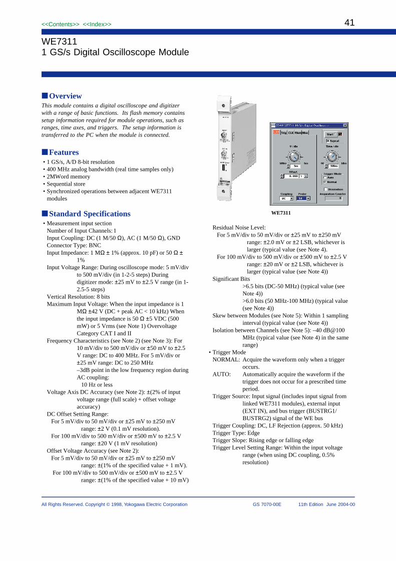
41<<Contents>> <<Index>>
All Rights Reserved. Copyright © 1998, Yokogawa Electric Corporation GS 7070-00E 11th Edition June 2004-00
WE73111 GS/s Digital Oscilloscope Module
OverviewThis module contains a digital oscilloscope and digitizerwith a range of basic functions. Its flash memory containssetup information required for module operations, such asranges, time axes, and triggers. The setup information istransferred to the PC when the module is connected.
Features• 1 GS/s, A/D 8-bit resolution• 400 MHz analog bandwidth (real time samples only)• 2MWord memory• Sequential store• Synchronized operations between adjacent WE7311
modules
Standard Specifications• Measurement input section
Number of Input Channels: 1Input Coupling: DC (1 M/50 Ω), AC (1 M/50 Ω), GNDConnector Type: BNCInput Impedance: 1 MΩ ± 1% (approx. 10 pF) or 50 Ω ±
1%Input Voltage Range: During oscilloscope mode: 5 mV/div
to 500 mV/div (in 1-2-5 steps) Duringdigitizer mode: ±25 mV to ±2.5 V range (in 1-2.5-5 steps)
Vertical Resolution: 8 bitsMaximum Input Voltage: When the input impedance is 1
MΩ ±42 V (DC + peak AC < 10 kHz) Whenthe input impedance is 50 Ω ±5 VDC (500mW) or 5 Vrms (see Note 1) OvervoltageCategory CAT I and II
Frequency Characteristics (see Note 2) (see Note 3): For10 mV/div to 500 mV/div or ±50 mV to ±2.5V range: DC to 400 MHz. For 5 mV/div or±25 mV range: DC to 250 MHz–3dB point in the low frequency region duringAC coupling:
10 Hz or lessVoltage Axis DC Accuracy (see Note 2): ±(2% of input
voltage range (full scale) + offset voltageaccuracy)
DC Offset Setting Range:For 5 mV/div to 50 mV/div or ±25 mV to ±250 mV
range: ±2 V (0.1 mV resolution).For 100 mV/div to 500 mV/div or ±500 mV to ±2.5 V
range: ±20 V (1 mV resolution)Offset Voltage Accuracy (see Note 2):
For 5 mV/div to 50 mV/div or ±25 mV to ±250 mVrange: ±(1% of the specified value + 1 mV).
For 100 mV/div to 500 mV/div or ±500 mV to ±2.5 Vrange: ±(1% of the specified value + 10 mV)
Residual Noise Level:For 5 mV/div to 50 mV/div or ±25 mV to ±250 mV
range: ±2.0 mV or ±2 LSB, whichever islarger (typical value (see Note 4).
For 100 mV/div to 500 mV/div or ±500 mV to ±2.5 Vrange: ±20 mV or ±2 LSB, whichever islarger (typical value (see Note 4))
Significant Bits>6.5 bits (DC-50 MHz) (typical value (seeNote 4))>6.0 bits (50 MHz-100 MHz) (typical value(see Note 4))
Skew between Modules (see Note 5): Within 1 samplinginterval (typical value (see Note 4))
Isolation between Channels (see Note 5): –40 dB@100MHz (typical value (see Note 4) in the samerange)
• Trigger ModeNORMAL: Acquire the waveform only when a trigger
occurs.AUTO: Automatically acquire the waveform if the
trigger does not occur for a prescribed timeperiod.
Trigger Source: Input signal (includes input signal fromlinked WE7311 modules), external input(EXT IN), and bus trigger (BUSTRG1/BUSTRG2) signal of the WE bus
Trigger Coupling: DC, LF Rejection (approx. 50 kHz)Trigger Type: EdgeTrigger Slope: Rising edge or falling edgeTrigger Level Setting Range: Within the input voltage
range (when using DC coupling, 0.5%resolution)
WE7311

42
All Rights Reserved. Copyright © 1998, Yokogawa Electric Corporation
<<Contents>> <<Index>>
GS 7070-00E 11th Edition June 2004-00
Trigger Sensitivity:DC to 1 MHz: 10% of the input voltage range (full scale)DC to 300 MHz: 20% of the input voltage range (full
scale)DC to 400 MHz: 70% of the input voltage range (full
scale)Trigger Level Accuracy (see Note 1)
±5% of the input voltage range (full scale)Trigger Position (During the Oscilloscope Mode):
±5 divPretrigger (During the Digitizer Mode): 0 to 100% of the
acquisition sampleTrigger Delay: During the oscilloscope mode: 0 up to 300 s
During the digitizer mode: 0 to 200 M samples (how-ever, the maximum value is the valuecorresponding to 300 s when converted intodelay time)
Trigger Output Able to output the acquisition trigger to thetrigger bus (BUSTRG1/BUSTRG2) of theWE bus.
Output Trigger Input Impedance (see Note 2): 1 MΩ or50 Ω
External Trigger Input Frequency Bandwidth (see Note 2):DC to 400 MHz (minimum voltage: 3 Vp-p)
External Trigger Input Voltage Range (see Note 2): ±4 VExternal Trigger Level Setting Range: ±4 V (0.1 V
resolution)The external trigger input and external clock input share
the same connector. •Time Axis
Time Axis Setting Range (During Oscilloscope Mode)10 ns/div to 50 s/div (in 1-2-5 steps)
Sampling Interval (During the Digitizer Mode)1 ns to 10 ms (in 1-2-5 steps) (For API, 1-2-2.5-4-5 steps)
Time Axis Accuracy (see Note 1): ±(25 ppm + 1 samplinginterval)
External Clock Input/Output (see Note 2): Able to input anexternal input signal (EXT IN) as a samplingclock. Able to input an external input signal(EXT IN) or the time base (CMNCLK) signalof the WE bus as a reference clock. Able tooutput the 10-MHz internal reference clock tothe time base (CMNCLK) of the WE bus.
External Clock Input Impedance: 1 MΩ or 50 ΩExternal Clock Input Voltage Range: ±4 VExternal Clock Input Threshold: ±2 V (0.1 V resolution)External Sampling Clock Input: Frequency Range /
Minimum Voltage: 10 MHz to 500 MHz/3 Vp-p
External Reference Clock Input Frequency Range/Minimum Voltage: 10 MHz/800 mVp-p
• FunctionsRecord Length: 100 to 2 MWord (1 Word unit, 1,000,001
words or more are only for single acquisition)Sequential Store: Memory partition (1 to 4096, 2n steps),
store count can be specified.Auto Setup: Automatically sets the voltage axis, time axis,
trigger level, etc.Calibration: Auto calibration and manual calibration
available
General SpecificationsStandard operating conditionsAmbient temperature: 23 ± 2°CAmbient humidity: 50 ± 10% RHWarm-up time: Minimum 30 minutesOperating conditions: Same as that of the measuring
stationStorage conditions
Storage temperature range: –20 to 60°CStorage humidity range: 20 to 80% RH (no condensa-
tion)Power consumption: 18 VA (typical value (see Note 4) at
100 V/50 Hz,External dimensions: Approx. 331.30 (W) × 2439.57
(H) × 2329.13 (D) mminch (projectionexcluded)
Weight: Approx. 0.81.76 kglbNumber of dedicated slots: 1Accessories: Module link connector (1 set),
User’s Manual (1)Note 1: When overvoltage is applied, the protective circuit is
activated, and the input coupling is switched to GND.Note 2: Value measured with the time base set to internal
clock under standard operating conditions afterwarm-up time has elapsed and after calibration.
Note 3: The –3 dB point when the input coupling is set to DC50 Ω with a 100-kHz sine wave with an amplitudecorresponding to ±3 divisions used as a reference.
Note 4: Typical value represents a typical or average value.It is not strictly guaranteed.
Note 5: Measured using the same range with the time baseset to internal clock under linked operation
AVAILABLE MODELS
Model Description
707311/HE 1 GS/s Digital Oscilloscope Module
Special Accessories (sold separately)
Accessory Model Description Order quantity
Module link connector
Passive probe
B9952RB
700944
1
110 : 1 10 MΩ 300 MHz Bandwidth
Dimensions
33
(1.3)
24
2.4
(9
.54
)
227 (8.94) 4.5
(0.18)
STATUS
INPUT
EXT IN
OPER SYNC
1M /10pF 42V
1M /50 4V
1GS/sDIGITAL OSCILLOSCOPE
50 5V or 5VrmsCAT
CAT
Unit: mm (inch)

43<<Contents>> <<Index>>
All Rights Reserved. Copyright © 1998, Yokogawa Electric Corporation GS 7070-00E 11th Edition June 2004-00
WE7521
WE75214-CH Timing Measurement Module
OverviewThe WE7521 is a 4-channel counter module.
It can measure one of five parameters (period, time interval,totalize count, up and down count,and frequency ratio) offour input signals.
The measured values are written to the acquisition memoryevery specified sampling interval.
In addition, the WE7521 includes a “time stamp mode” inwhich the time is recorded when any of the four inputsignals change.
Features• Arbitrarily combine 4 channels of input, and perform
measurement on one of five parameters (period, timeinterval, totalize count, up and down count, and frequencyratio)
• Store up to 1 Mpoints of measured data continuously (upto 4 Mpoints in time stamp mode)
• 5 ns time resolution, maximum sampling frequency of 500kSps (in counter mode)
Performance SpecificationsNumber of Inputs: 4Input Format: Non-isolated, unbalancedConnector Type: BNCInput Coupling: DC/AC–3 dB Point During AC Coupling: 10 Hz (Typical value
(see Note 1) )Input Threshold Level: Set in the range ±20 V (0.1 V
resolution) for each inputThreshold Level Accuracy: ±(5% of the specified value +
150 mV)Input Impedance: 1 MΩ ±1%Input Filter: OFF/100kHz/10kHz/1kHz (–3 dB point)
(Typical value (see Note 1) )Input Sensitivity: When hysteresis width is NORMAL and
frequency is 1 MHz or less: 1.0 Vpp (Typicalvalue (see Note 1) )When hysteresis width is WIDE andfrequency is 1 MHz or less: 3.0 Vpp (Typicalvalue (see Note 1) )
Hysteresis Width: NORMAL/WIDEHysteresis Direction: Center/Upper/Lower (common to all
inputs)Maximum Input Voltage: ±42.4 V (DC + ACpeak)
(Overvoltage Category CAT I and II)
Specifications for the Counter ModeNumber of Counters: 4Measurement Slope: Rising edge or falling edgeMeasurement Function: Period, time interval, totalize
count, up and down count, and frequency ratioDisplay Resolution: During period/time interval
measurement: 5 nsMinimum Input Pulse Width: 50 nsMinimum Input Edge Interval: For all input edges during
up and down count: 50 nsData Width: During period/time interval measurement: 32
bitsDuring totalize count/up and down count/frequency ratio measurement: 29 bits (seeNote 2)
Acquisition Mode: Trigger, free run, gate (level), gate (edge)Specifications for Each Measurement Functiona) Period
Measurement range: 100 ns to 20 s (see Note 3)Resolution: (5 ns ± 2 trigger error)Accuracy: Resolution ± (time base aging 3 sampling
interval) ±5 nsb) Time interval
Measurement range: 100 ns to 20 s (see Note 3)Resolution: (±5 ns ± input A trigger error ± input B
trigger error)Accuracy: Resolution ± (time base aging 3 sampling
interval) ± trigger level timing error ±5 nsc) Totalize count
Counting capacity: 0 to 536,870,911 (see Note 3)Counting control: Through measurement start/stop or
gate (pulse) using the input signalCounting error: ±1 count (when the counter is controlled
through measurement start/stop)(input B trigger error [rising] ±input B trigger error [falling])
input A period±1 count ±
(When controlled using gate/input A: signalto be measured, input B: gate signal)
d) Up and down countCounting capacity: –268,435,456 to 268,435,455 (see
Note 4)Counting control: Through measurement start/stop or
reset (Z phase) using the input signalCounting error: ±1 count (when the counter is controlled
through measurement start/stop)

44
All Rights Reserved. Copyright © 1998, Yokogawa Electric Corporation
<<Contents>> <<Index>>
GS 7070-00E 11th Edition June 2004-00
input B trigger error
input A period±1 count ± (N=1, 2, 4)
(When controlled using reset/input A: signalto be measured, input B: reset signal)
Multiplication: 1, 2, and 4e) Frequency ratio
Counting capacity: 0 to 536,870,911 when multiplyingfactor is 1, 0 to 33,554,431.9 when
multiplying factor is 16, 0 to 4,194,303.99when multiplying factor is
128, 0 to 524,287.999 when multiplyingfactor is 1024 (see Note 3)
Counting control: Measurement start/stop 2 input B trigger error
input A period Counting error: ±1 count ± (N=1, 16, 128, 1024)
Multiplication: 1, 16, 128, and 1024Acquisition Memory
Maximum record length: 1 Mpoint/CHMemory partition: 1, 2, 4, 8, 16,32, 64, 128, and 256
(only during trigger mode)Sampling interval: 2µs to 10sSampling signal source: Internal time base, bus clock,
and input signalTrigger source: Input signal, measured value, bus trigger
signal of the measuring stationHold off: Record length to 1,048,576 points (trigger
mode), 1 to 1,048,576 points (gate(edge) mode)
Data hold function: Hold previous value or Update onnew value (see Note 5)
Specifications for the Time Stamp ModeNumber of Inputs: 4Measurement Slope: Rising edge, falling edge, and bothMaximum Measurement Time: Approximately 360 hours
(5 248 ns)Display Resolution: 5 ns
Resolution: (±5 ns ± 2 trigger error)Accuracy: Resolution ± (time base aging sampling
interval) ±5 nsMinimum Pulse Width: 200 nsData Format: 32 bits (24-bit time stamp data + 8-bit input
edge data)Acquisition Mode: Free run only (see Note 6)Record Length: 4 Mpoints
Reference Time Axis AccuracyFrequency StabilityAging: ±1.5 10-6 /yearTemperature Characteristics±2.0 10-6 (5°C to 40°C)
Note 1: Typical value represents a typical or average value.It is not strictly guaranteed.
Note 2: The measured data length is 29 bits, but the datawidth is expanded to 32 bits.
Note 3: When the measurement range is exceeded, the data isset to invalid value.
Note 4: When the measurement range is exceeded, the datareturns to the minimum (maximum) value of thecounting capacity and continues the measurement.
Note 5: You can select a mode in which the previous value isheld or a mode in which an invalid value is held whenthere is no input change during the sampling interval.
Note 6: If the rate of change of input is too fast and the datacannot be saved, the measurement is stopped.
General SpecificationsSafety Standard: Complies with CSA C22.2 No. 1010.1
and EN61010-1, conforms to JIS C1010-1Warm-Up Time: At least 30 minutesOperating Conditions: Same as those of the measuring
stationStorage ConditionsTemperature: –20°C to 60°CHumidity: 20% to 80% RH (no condensation)Power Consumption: 8 VA (typical value (see Note) at 100
V/50 Hz)External dimensions: Approx. 331.3(W)
2439.54(H) 2329.13(D) mminch(projections excluded)
Weight: Approx. 0.71.54 kglbNumber of Used Slots: 1Standard Accessories: User’s manual (this manual) (1)
Note Typical value represents a typical or average value.It is not strictly guaranteed.
AVAILABLE MODELS
Model Description
707521/HE 4-CH Timing Measurement Module
DimensionsUnit: mm(inch)
33
24
2.4
(9
.54
)
227 (8.94) 4.5
START
INPUT
IN1
IN2
IN3
IN4
42.4VpkCAT
4-CH TIMINGMEASUREMENT
1M
(1.3) (0.18)
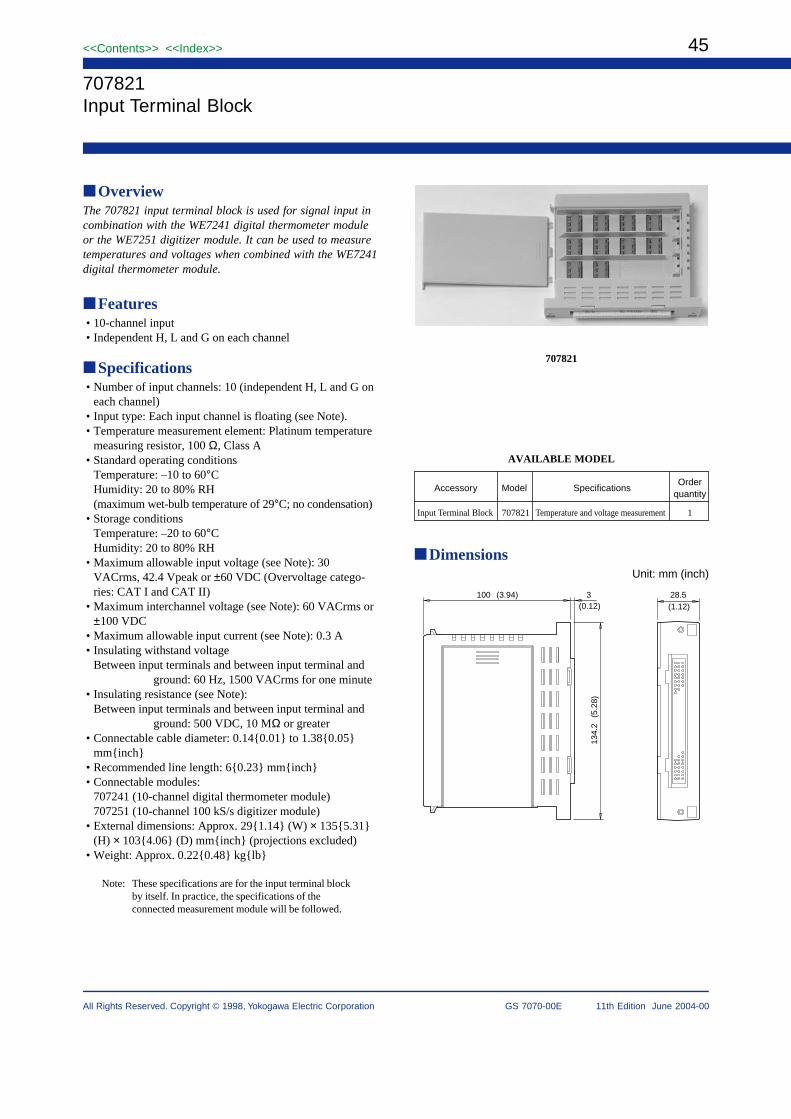
45<<Contents>> <<Index>>
All Rights Reserved. Copyright © 1998, Yokogawa Electric Corporation GS 7070-00E 11th Edition June 2004-00
707821
707821Input Terminal Block
OverviewThe 707821 input terminal block is used for signal input incombination with the WE7241 digital thermometer moduleor the WE7251 digitizer module. It can be used to measuretemperatures and voltages when combined with the WE7241digital thermometer module.
Features• 10-channel input• Independent H, L and G on each channel
Specifications• Number of input channels: 10 (independent H, L and G on
each channel)• Input type: Each input channel is floating (see Note).• Temperature measurement element: Platinum temperature
measuring resistor, 100 Ω, Class A• Standard operating conditions
Temperature: –10 to 60°CHumidity: 20 to 80% RH(maximum wet-bulb temperature of 29°C; no condensation)
• Storage conditionsTemperature: –20 to 60°CHumidity: 20 to 80% RH
• Maximum allowable input voltage (see Note): 30VACrms, 42.4 Vpeak or ±60 VDC (Overvoltage catego-ries: CAT I and CAT II)
• Maximum interchannel voltage (see Note): 60 VACrms or±100 VDC
• Maximum allowable input current (see Note): 0.3 A• Insulating withstand voltage
Between input terminals and between input terminal andground: 60 Hz, 1500 VACrms for one minute
• Insulating resistance (see Note):Between input terminals and between input terminal and
ground: 500 VDC, 10 MΩ or greater• Connectable cable diameter: 0.140.01 to 1.380.05
mminch• Recommended line length: 60.23 mminch• Connectable modules:
707241 (10-channel digital thermometer module)707251 (10-channel 100 kS/s digitizer module)
• External dimensions: Approx. 291.14 (W) × 1355.31(H) × 1034.06 (D) mminch (projections excluded)
• Weight: Approx. 0.220.48 kglb
Note: These specifications are for the input terminal blockby itself. In practice, the specifications of theconnected measurement module will be followed.
AVAILABLE MODEL
Accessory Model SpecificationsOrder
quantity
Input Terminal Block 707821 Temperature and voltage measurement 1
DimensionsUnit: mm (inch)
100 (3.94) 3(0.12)
134.
2(5
.28)
28.5(1.12)

46
All Rights Reserved. Copyright © 1998, Yokogawa Electric Corporation
<<Contents>> <<Index>>
GS 7070-00E 11th Edition June 2004-00
707823
70782316-Bit Digital Input Terminal Box
OverviewThe 707823 16-bit digital input terminal box is used incombination with a WE7262 32-bit digital I/O module. Itconverts an external contact signal, as well as a voltagesignal ranging up to ±35 V, into a TTL signal to feed it tothe WE7262 module.
A maximum of two 707823 digital input terminal boxes canbe connected to each WE7262 module, where each box ispowered by the module via cable.
Features• Couples a 16-bit contact signal or voltage signal with the
WE7262 module.• Compatible with voltage signals ranging up to ±35 V.• Allows the input threshold level to be selected from 2 and
6 V by wiring.• Isolation among binary-digit inputs and between each
input terminal and the WE7262 module
SpecificationsNumber of input points: 16 (16 bits)Input voltage
H level: +2.5 V to +35 V (between H1 and L), or +8V to +35 V (between H2 and L)
L level: –35 V to +1 V (between H1 and L), or –35V to +5 V (between H2 and L)
Input currentH level: +1 mA to +8 mAL level: 10 µA or below
Response time: 100 µs (Typical value (see Note))Input format: Each bit is isolated from casing, WE7262
module, and each other.
General SpecificationsSafety standard: Complies with CSA C22.2 No. 1010.1
and EN61010-1, conforms to JIS C1010-1Maximum allowable input voltage
Between H1 and L, or H2 and L: (35 VDC + AC peak(Overvoltage Category: CAT I and II.Pollution degree: 1 and 2)
Maximum common mode voltageBetween input terminal and WE7262: ±250 VDC or 250
VACrmsBetween input terminal and casing: ±250 VDC or 250
VACrmsBetween input terminals: ±250 VDC or 250 VACrms
Withstanding voltage
Between input terminal and WE7262: 2300 VACrms forone minute
Between input terminal and casing: 2300 VACrms forone minute
Between input terminals: 2300 VACrms for one minute
Operating conditionsTemperature: 5°C to 40°CHumidity: 20 to 80% RH (no condensation)
Storage conditionsTemperature: –20°C to 60°CHumidity: 20 to 80% RH
Diameter of cable that can be connected: 0.14 mm to 1.38mm
Recommended stripped length of cable: 6 mm maximumConnectable module:
WE7262 (Model: 707262) 32-bit digital I/O moduleMaximum power consumption: 0.1 WExternal dimensions: Approx. 973.8 (W) × 421.7 (H)
× 2349.2 (D) mminch (projectionsexcluded)
WeightMain unit: Approx. 0.51.1 kglbCable: Approx. 0.30.66 kglb
Standard accessory: Shielded cable (1) (for connectionbetween 707823 and 707262, 2 m), User’sManual (1)
Note Typical value represents a typical or average value.It is not strictly guaranteed.
AVAILABLE MODEL
Description Model Specifications Order quantity
16-bit Digital Input Terminal Box
707823 1For WE7262 contact input
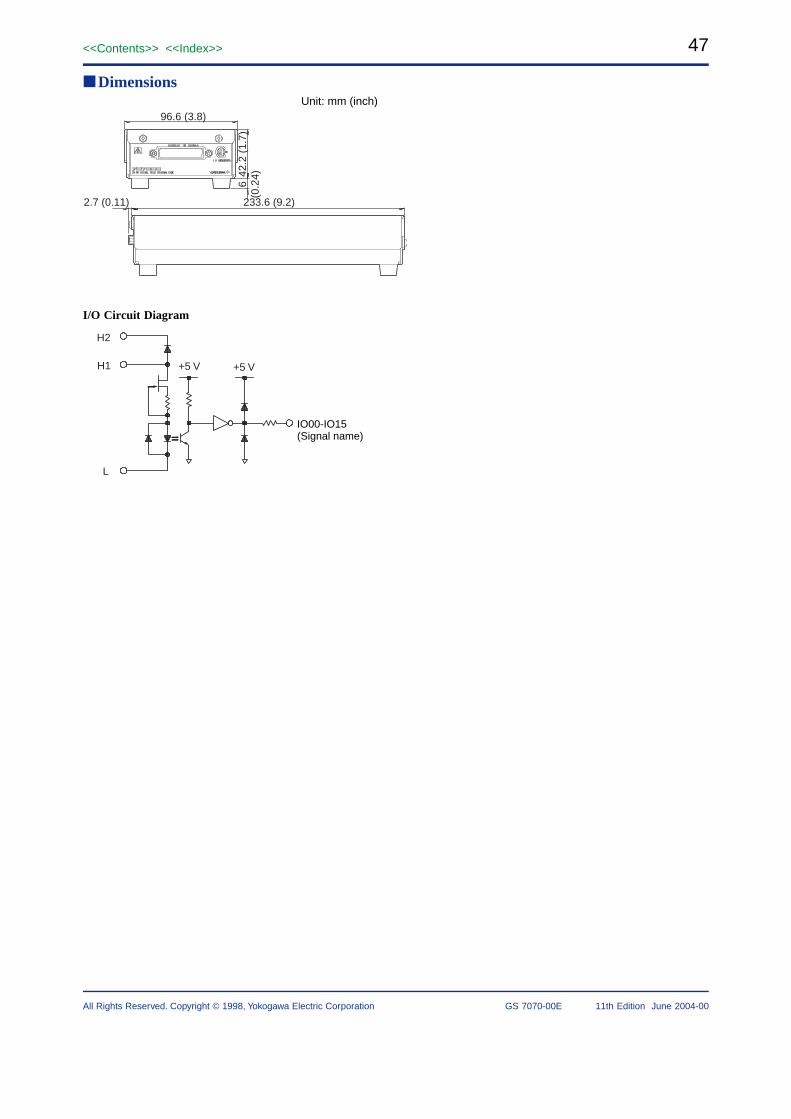
47<<Contents>> <<Index>>
All Rights Reserved. Copyright © 1998, Yokogawa Electric Corporation GS 7070-00E 11th Edition June 2004-00
DimensionsUnit: mm (inch)
96.6 (3.8)
42.2
(1.
7)6
(0.2
4)
2.7 (0.11) 233.6 (9.2)
I/O Circuit Diagram
IO00-IO15(Signal name)
H1
H2
L
+5 V+5 V

48
All Rights Reserved. Copyright © 1998, Yokogawa Electric Corporation
<<Contents>> <<Index>>
GS 7070-00E 11th Edition June 2004-00
707824
70782416-Bit Digital Output Terminal Box
OverviewThe 707824 16-bit digital output terminal box is used incombination with the WE7262 32-bit digital I/O module. Itconverts the CMOS-level output of the WE7262 module tocontact signals to feed them to external equipment.
A maximum of two 707824 digital output terminal boxescan be connected to each WE7262 module, where each boxis powered by the module via cable.
Features• 16-bit MOS-level contact output• 35-V/0.3-A output capacity• Isolation among binary-digit outputs and between each
output terminal and the WE7262 module
Performance SpecificationsNumber of output points: 16 (16 bits)Maximum applicable voltage (with the power turned off):
±35 VMaximum output contact current: ±300 mATurn-on resistance: 4 Ω or belowLeakage current (with the power turned off): 100 µA or
belowResponse time: 3 ms (Typical value (see Note))Output format: MOS-level contact outputEach bit is isolated from casing, WE7262 module, and
each other.
General SpecificationsSafety standard: Complies with CSA C22.2 No. 1010.1
and EN61010-1, conforms to JIS C1010-1Maximum common mode voltage
Between input terminal and WE7262: ±250 VDC or 250VACrms
Between input terminal and casing: ±250 VDC or 250VACrms
Between input terminals: ±250 VDC or 250 VACrmsWithstanding voltage
Between input terminal and WE7262: 2300 VACrms forone minute
Between input terminal and casing: 2300 VACrms forone minute
Between input terminals: 2300 VACrms for one minuteOperating conditions
Temperature: 5°C to 40°CHumidity: 20 to 80% RH (no condensation)
Storage conditionsTemperature: –20°C to 60°CHumidity: 20 to 80% RH
Protection: Protection against overvoltage (each output isprotected with a fuse)
Diameter of cable that can be connected: 0.14 mm to 1.38mm
Recommended stripped length of cable: 6 mm maximumConnectable module:
WE7262 (Model: 707262) 32-bit digital I/O moduleMaximum power consumption: 1 WExternal dimensions: Approx. 973.8 (W) × 421.7 (H)
× 2349.2 (D) mminch (projectionsexcluded)
WeightMain unit: Approx. 0.51.1 kglbCable: Approx. 0.30.66 kglb
Standard accessory: Shielded cable (1) (for connectionbetween 707824 and 707262, 2 m), User’sManual (1)
Note Typical value represents a typical or average value.It is not strictly guaranteed.
AVAILABLE MODEL
Description Model Specifications Order quantity
16-bit Digital Output Terminal Box
707824 1For WE7262 contact output

49<<Contents>> <<Index>>
All Rights Reserved. Copyright © 1998, Yokogawa Electric Corporation GS 7070-00E 11th Edition June 2004-00
DimensionsUnit: mm (inch)
2.7 (0.11) 233.6 (9.2)
96.6 (3.8)
42.2
(1.
7)6
(0.2
4)
I/O Circuit Diagram
H
L
0.5 A+5 V +5 V
IO00-IO15(Signal name)
Fuse

50
All Rights Reserved. Copyright © 1998, Yokogawa Electric Corporation
<<Contents>> <<Index>>
GS 7070-00E 11th Edition June 2004-00
7078 34
7078 31/7078 32/7078 33/7078 34Optical Fiber Cables
OverviewThese optical fiber cables are connected with the opticalinterface modules and optical interface cards.
Features• These multi-mode optical fiber cables have dual SC
connectors for easy setup.
Specifications• Cable lengths:7078 31: 2 meters (6.56 ft)7078 32: 5 meters (16.4 ft)7078 33: 10 meters (32.8 ft)7078 34: 1 meter (3.28 ft)• Fiber optic core diameter: 62.5 (50) µm• Clad diameter: 125 µm• Core noncircularity: Maximum 6%• Clad noncircularity: Maximum 2%• Core/clad eccentricity: Maximum 6%• Numerical aperture (NA): 0.275 ±0.03• Buffer layer: Silicon resin• Coating: Polyamide resin (external diameter: 0.9 ±0.1)• Protective coating: 1.2 core fiber optic cord (consisting of
a fiber-optic core covered with a PVC jacket)• Jacket material: PVC (light green), 2.80.11 × 5.60.22
mminch• Weight: Approx. 14 kg/km• Minimum bending radius
When extended: 602.36 mminch (short-radiusdirection only)
When fixed: 301.18 mminch (short-radius directiononly)
• Allowable instantaneous tensile stress: 196N
AVAILABLE MODEL
Model Description
7078 31 Optical Fiber Cable, 2 meters
7078 32 Optical Fiber Cable, 5 meters
7078 33 Optical Fiber Cable, 10 meters
7078 34 Optical Fiber Cable, 1 meter