General Resistor Seriesresistors are then color code marked. Ayrton-Perry Winding Winding of two...
86
General Resistor Series Direct Electronics Industry Co., Ltd. China: 12F, Zhong Xing Industry Bld., Chuang Ye Road, Nan Shan District, Shen Zhen City, Guang Dong, China 518054 Tel: +86 755 26055363; Fax: +86 755 26055365 Taiwan: No.137, Sec. 1, Zhongxing Rd., Wugu District, New Taipei City, Taiwan, R.O.C. 24872 Tel: +886 2981 0109 Fax: +886 2988 7487 Version: July 2, 2019 Electronics Tech. Web: www.direct-token.com Email: [email protected]
Transcript of General Resistor Seriesresistors are then color code marked. Ayrton-Perry Winding Winding of two...

General Resistor
Series
Direct Electronics Industry Co., Ltd.
China: 12F, Zhong Xing Industry Bld., Chuang Ye Road,
Nan Shan District, Shen Zhen City,
Guang Dong, China 518054
Tel: +86 755 26055363; Fax: +86 755 26055365
Taiwan: No.137, Sec. 1, Zhongxing Rd., Wugu District,
New Taipei City, Taiwan, R.O.C. 24872
Tel: +886 2981 0109 Fax: +886 2988 7487
Version:
July 2, 2019
Electronics Tech.
Web: www.direct-token.com
Email: [email protected]

China Factory: +86 755 26055363
http://www.direct-token.com
[email protected] Taiwan Factory: +886 2 29810109 Index: I
Production Index
General Resistor Series
Resistor Glossary & Terminology ................................................................................................. 1
Glossary & Terminology ...................................................................................................................... 1
Select Optimum Resistors ............................................................................................................. 3
Select Optimum Resistors .................................................................................................................... 3
Pulse Load Anti-Surge Resistors (RCR) ....................................................................................... 5
Product Introduction ............................................................................................................................. 5 General Specifications ......................................................................................................................... 6 Power Rating ........................................................................................................................................ 6
Loading Conditions .............................................................................................................................. 7 Order Codes ......................................................................................................................................... 7
Carbon Film Resistors (CF) .......................................................................................................... 8
Product Introduction ............................................................................................................................. 8 Dimensions & Specifications ............................................................................................................... 9 Electrical Performance ....................................................................................................................... 10 Order Codes ....................................................................................................................................... 10
Light Dependent Resistors (PGM) .............................................................................................. 11
Product Introduction ........................................................................................................................... 11 Terminology ....................................................................................................................................... 12 Physical and Environmental Characteristics ...................................................................................... 13 Configurations & Dimensions ............................................................................................................ 14 PGM5**** Electronics Characteristics .............................................................................................. 15 PGM55** Electronics Characteristics ................................................................................................ 15 Configurations & Dimensions ............................................................................................................ 16 PGM12** Electronics Characteristics ................................................................................................ 17 PGM12**-MP Electronics Characteristics ......................................................................................... 17 Configurations & Dimensions ............................................................................................................ 18 PGM20** Electronics Characteristics ................................................................................................ 19 PGM20**-PP Electronics Characteristics .......................................................................................... 19 Order Codes ....................................................................................................................................... 19
Ceramic Housed Cement Resistors (SQ) .................................................................................... 20
Product Introduction ........................................................................................................................... 20 SQP Dim. ........................................................................................................................................... 21 SQM Dim. .......................................................................................................................................... 22 SQT Dim. ........................................................................................................................................... 23 SQH Dim. ........................................................................................................................................... 24 SQZ Dim. ........................................................................................................................................... 25 Electrical Performance ....................................................................................................................... 26 Material Specifications ....................................................................................................................... 26 Order Codes ....................................................................................................................................... 26
Carbon Composition Resistors (CCR) ........................................................................................ 27
Product Introduction ........................................................................................................................... 27 Dimensions ......................................................................................................................................... 28 Ratings Specifications ........................................................................................................................ 28

China Factory: +86 755 26055363
http://www.direct-token.com
[email protected] Taiwan Factory: +886 2 29810109 Index: II
Derating Curve ................................................................................................................................... 29 Performance ....................................................................................................................................... 30 Order Codes ....................................................................................................................................... 30
Fusible Resistors (FRN, FKN, FSQ) .......................................................................................... 31
Product Introduction ........................................................................................................................... 31 Specifications (FRN) .......................................................................................................................... 32 Specifications (FKN) ......................................................................................................................... 33 Specifications (FSQ) .......................................................................................................................... 33 Characteristics .................................................................................................................................... 34 Application Notes ............................................................................................................................... 35 Order Codes ....................................................................................................................................... 35
Metal Oxide Resistors (RSS, RSN) ............................................................................................ 36
Product Introduction ........................................................................................................................... 36 Specifications & Dimensions ............................................................................................................. 37 Electrical Performance ....................................................................................................................... 38 Application Notes ............................................................................................................................... 38 Order Codes ....................................................................................................................................... 39
Precision Resistors (MF) ............................................................................................................. 40
Product Introduction ........................................................................................................................... 40 Dimensions & Specifications ............................................................................................................. 41 Resistance Range ............................................................................................................................... 42 Electrical Performance ....................................................................................................................... 42 Order Codes ....................................................................................................................................... 43
Thermal Cut-offs Resistors (FKU, FRU) ................................................................................. 44
Product Introduction ........................................................................................................................... 44 General Specifications ....................................................................................................................... 45 Electrical Performance ....................................................................................................................... 46 Order Codes ....................................................................................................................................... 46
Wire Wound Resistors (KNP) ..................................................................................................... 47
Product Introduction ........................................................................................................................... 47 General Specifications ....................................................................................................................... 48 Electrical Performance ....................................................................................................................... 49 Application Notes ............................................................................................................................... 50 Order Codes ....................................................................................................................................... 50
Non-Inductive Wire wound Resistor (KNPN) ............................................................................ 51
Product Introduction ........................................................................................................................... 51 General Specifications ....................................................................................................................... 52 Electrical Performance ....................................................................................................................... 53 Application Notes ............................................................................................................................... 54 Order Codes ....................................................................................................................................... 54
Power Wire wound Resistor (KNP-R) ........................................................................................ 55
Product Introduction ........................................................................................................................... 55 Technical Specifications ..................................................................................................................... 56 Electrical Performance ....................................................................................................................... 57 Application Notes ............................................................................................................................... 57 Order Codes ....................................................................................................................................... 57

China Factory: +86 755 26055363
http://www.direct-token.com
[email protected] Taiwan Factory: +886 2 29810109 Index: III
High Precision Wire wound Resistor (BWW) ............................................................................ 58
Product Introduction ........................................................................................................................... 58 Technical Specifications ..................................................................................................................... 59 Electrical Performance ....................................................................................................................... 60 Application Notes ............................................................................................................................... 60 Order Codes ....................................................................................................................................... 60
Zero Ohm & Jumper Wire Resistors (ZO, JW) .......................................................................... 61
Product Introduction ........................................................................................................................... 61 ZO General Specification ................................................................................................................... 62 JW General Specification ................................................................................................................... 62 Electrical Performance ....................................................................................................................... 63 Order Codes ....................................................................................................................................... 63
Wirewound Resistor (KNP-VE/LF) ............................................................................................ 64
Product Introduction ........................................................................................................................... 64 Technical Specifications ..................................................................................................................... 65 Electrical Performance ....................................................................................................................... 66 Order Codes ....................................................................................................................................... 66
Power Wirewound Vitreous Enameled Resistors (DRB20) ........................................................ 67
Product Introduction ........................................................................................................................... 67 Technical Specifications ..................................................................................................................... 68 Specification ....................................................................................................................................... 69 Electrical Performance ....................................................................................................................... 69 Application Notes ............................................................................................................................... 70 Order Codes ....................................................................................................................................... 71
Long Lead Wirewound Enameled Resistors (DRB16) ............................................................... 72
Product Introduction ........................................................................................................................... 72 Technical Specifications ..................................................................................................................... 73 Electrical Performance ....................................................................................................................... 74 Derating Curve ................................................................................................................................... 74 Order Codes ....................................................................................................................................... 75
Power Metal Film Flame-Proof Resistors (FMF) ....................................................................... 76
Product Introduction ........................................................................................................................... 76 Dimensions & Specifications ............................................................................................................. 77 Resistance & TCR .............................................................................................................................. 78 Electrical Performance ....................................................................................................................... 79 Derating Curve & Temperature .......................................................................................................... 80 Order Codes ....................................................................................................................................... 81 General Information ........................................................................................................................... 82

China Factory: +86 755 26055363
http://www.direct-token.com
[email protected] Taiwan Factory: +886 2 29810109 Page: 1/82
Resistor Glossary & Terminology
Glossary & Terminology
Resistor Glossary & Terminology
Fusible Resistor (Fuse Resistor, Circuit Protect Resistor)
A resistor designed to protect a circuit against overload; its resistance limits current flow and thereby
protects against surges when power is first applied to a circuit; its fuse characteristic opens the circuit
when current drain exceeds design limits.
Thermal Cutoff Resistor
A thermal fuse is a cutoff which uses a one-time fusible link. Unlike the thermostat which
automatically resets itself when the temperature drops, the thermal fuse is more like an electrical fuse:
a single-use device that cannot be reset and must be replaced when it fails or is triggered. A thermal
fuse is most useful when the overheating is a result of a rare occurrence, such as failure requiring
repair (which would also replace the fuse) or replacement at the end of service life.
Direct offers "Thermal Cut-off Resistor", a thermal Cut-offs is a fusible alloy and a resistor is a voltage
divider, both are surrounded by ceramic cement with special resin. Under normal operating
temperatures the fusible alloy joins the two lead wires within the body of the cutoff and the power
resistor acts as a normal function resistor. When the preset temperature of the cutoff is reached, the
fusible alloy melts and with the aid of the special resin, complete cutoff is ensured.
Thermal fuse resistors are usually found in heat-producing electrical appliances such as coffeemakers
and hair dryers. They function as safety devices to disconnect the current to the heating element in case
of a malfunction (such as a defective thermostat) that would otherwise allow the temperature to rise to
dangerous levels, possibly starting a fire.
Anti-Surge Resistor (RCR)
Surges in electronic circuits are caused by internal conditions — switching operations from other
electronic components or due to external conditions on the AC power mains — switching operations in
the power grid or from nearby lightning strikes, either directly to the power distribution system or to
nearby ground. Electronic products have to be surge immune to ensure their continued reliable
operation if subjected to realistic levels of surge voltages, and they are required to comply with safety
requirements. Direct's RCR series is a perfect fit when an anti-surge resistor is required.
Light Dependent Resistor (LDR)
A photoresistor or light dependent resistor or cadmium sulfide (CdS) cell is a resistor whose resistance
decreases with increasing incident light intensity. It can also be referenced as a photoconductor.
A photoresistor is made of a high resistance semiconductor. If light falling on the device is of high
enough frequency, photons absorbed by the semiconductor give bound electrons enough energy to
jump into the conduction band. The resulting free electron (and its hole partner) conduct electricity,
thereby lowering resistance.

China Factory: +86 755 26055363
http://www.direct-token.com
[email protected] Taiwan Factory: +886 2 29810109 Page: 2/82
Carbon Composition Resistor (CCR)
CCR is made up of a solid rod of conductive composite material, the chemical composition of which is
altered to produce different resistance values. The general composition consists of the carbon
conductor and ceramic filler materials. By altering the ratio of filler to conductor it is possible to
change the resistance value. Interference-fit end caps are attached to the rods, leads are welded onto
these caps, and the resistor body is then protected with a specially formulated epoxy coating. The
resistors are then color code marked.
Ayrton-Perry Winding
Winding of two wires in parallel but opposite directions to give better cancellation of magnetic fields
than is obtained with a single winding.
Wire wound technology has long been known as a leading technology for power resistor needs. The
most critical drawback with this technology is that it is inherently inductive. This is logical given that a
wire wound inductor and wire wound resistors are made with essentially the same materials and
processes. This fact limits the use of wire wounds for applications with high switching speeds, which
require low inductance.
Now the same standard wire wounds can be used for these applications by using a non-inductively
wound version. This manufacturing method greatly reduces the inductance of any given resistor size
and value combination, however it does not completely eliminate the inductance. A non-inductively
wound wire wound has one winding in one direction and one in the other direction; known as Ayrton
Perry winding. This non-inductive winding is available in all Direct standard wire-wound resistor
series.

China Factory: +86 755 26055363
http://www.direct-token.com
[email protected] Taiwan Factory: +886 2 29810109 Page: 3/82
Select Optimum Resistors
Select Optimum Resistors
Select Resistors with Optimum Technology to Best Match the Performance
Comparison of Axial Lead Resistor Functions Table
Class Advantage Disadvantage
Carbon Resistors Cheap, General Purposes High TCR,
Metal Film Resistors Low TCR, Tight Tolerance, High Stability Fair Withstanding Voltage
Metal Oxide Resistors Replace high resistance wire wound resistor, Good
withstanding voltage
Resistance Range Limitation, Fair
Tolerance
Wire wound Resistors High Pulse Load, Anti-Surge, High Stability High Inductance, Resistance
Range Limitation
Non-Inductive Resistors High Pulse Load, Anti-Surge, High Stability Resistance Range Limitation,
High Cost
Ceramic Housed Cement
Resistors
Rugged, excellent heat dissipation, withstanding high
temperature Heavy Weight, Big Volume
Metal Glaze Resistors High Pulse Load, Anti-Surge, High Stability High TCR, Fair Tolerance
Alloy Strip Low TCR, Low Ohmic Fair Tolerance

China Factory: +86 755 26055363
http://www.direct-token.com
[email protected] Taiwan Factory: +886 2 29810109 Page: 4/82
Comparison of Axial Lead Resistor Characteristics Table
Characteristics
Thin Film Thick Film Wire Wound Alloy
Strip Carbon
Film
Metal
Film
Metal
Oxide Film
Metal
Glaze Film Standard
Non
-Inductive
Tolerance
(%)
±0.01 √ √
±0.02 √ √
±0.05 √ √
±0.1 √ √
±0.25 √ √
±0.5 √ √
±1.0 √ √ √ √ √
±2.0 √ √ √ √ √ √
±5.0 √ √ √ √ √ √
±10 √ √ √ √ √ √
Temperature
Coefficient
(PPM/℃)
5 √
10 √
15 √
25 √ √ √
50 √ √ √ √
100 √ √ √ √ √
200 √ √ √ √ √
400 √ √ √ √ √
1,000 √
Operating
Temperature
Range (℃)
200 √ √
165 √ √ √ √ √ √
125 √ √ √ √ √ √ √
70 √ √ √ √ √ √ √
40 √ √ √ √ √ √
10 √ √ √ √ √ √
Wattage
(W)
1/16
1/8 √ √
1/4 √ √ √ √ √
1/2 √ √ √ √ √ √ √
1 √ √ √ √ √ √ √
2 √ √ √ √ √ √ √
3 √ √ √ √ √ √ √
5 √ √ √ √
10 √ √ √
Resistance
Range (Ω)
0.1
1 √ √ √
10 √ √ √ √ √ √
100 √ √ √ √ √ √
1K √ √ √ √ √ √
10K √ √ √ √ √
100K √ √ √ √
1M √ √ √ √
10M √ √ √
Volume Size Standard Standard Standard Standard Standard Bigger Compact
High Frequency Available Available Available Available None Available Available
Cost Cheap Fair Fair Fair High High Fair
Noise Fair Good Fair Fair Fair Good Good
Stability Fair Excellent Good Good Excellent Good Excellent

China Factory: +86 755 26055363
http://www.direct-token.com
[email protected] Taiwan Factory: +886 2 29810109 Page: 5/82
Pulse Load Anti-Surge Resistors
(RCR)
Product Introduction
Features :
High power at small sizes
Max working voltage up to 3000V
Lead (Pb)-free and RoHS compliant
Operating temperature range: -20℃~+155℃
Metal glaze power film, axial leaded type
Max overload voltage 5000V, Tolerances: J
(±5%)
Applications :
Ballasts
Amplifiers
Industrial power supplies
Telecommunications
Household appliances
Automotive circuits, Computer, Instrumentation
A new range of anti-surge axial leaded power resistors, metal
glaze resistive element on ceramic substrates, from Direct
Electronics.
A carbon film resistor replacement, the new RCR series
thick-film style resistors offer numerous benefits over the
previous style devices, namely reduced costs, excellent thermal
compliance, optimized a variety of surge capabilities and better
solder joint reliability against temperature cycles.
Direct succeeded in commercializing the compact thick-film
type leaded resistors with high power and high anti surge characteristics, meeting latest design
engineer requirements and making the parts suitable for industrial, measurement and
telecommunication applications as well as for automotive circuits, like Electrical Control Units (ECU)
and Air-Bag Systems.
The anti-surge characteristics of Direct's latest metal glaze power film style resistors are superior to
standard metal film resistors. The power film types of RCR resistors are available: 0.25W to 10W
power rating, max working voltage up to 3000V and max overload voltage 5000V. The resistance
range is 1Ω ~ 100MΩ at operating temperature range -20℃~+155℃.
All RCR series devices are RoHS-compliant, and compatible with high temperature soldering
processes normally employed for lead free solders. Resistors are also available in various forming
styles and different leads for different applications. Contact us with your specific needs. For more
information, please link to Direct official website "General Purpose Resistors".
Thick-film anti-surge resistor handles large pulse loading.
China Factory: +86 755 26055363
http://www.direct-token.com
[email protected] Taiwan Factory: +886 2 29810109 Page: 6/82
General Specifications
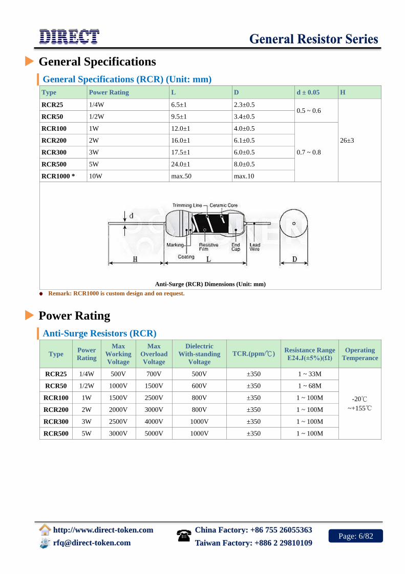
General Specifications (RCR) (Unit: mm)
Type Power Rating L D d ± 0.05 H
RCR25 1/4W 6.5±1 2.3±0.5 0.5 ~ 0.6
26±3
RCR50 1/2W 9.5±1 3.4±0.5
RCR100 1W 12.0±1 4.0±0.5
0.7 ~ 0.8
RCR200 2W 16.0±1 6.1±0.5
RCR300 3W 17.5±1 6.0±0.5
RCR500 5W 24.0±1 8.0±0.5
RCR1000 * 10W max.50 max.10
Anti-Surge (RCR) Dimensions (Unit: mm)
Remark: RCR1000 is custom design and on request.
Power Rating
Anti-Surge Resistors (RCR)
Type Power
Rating
Max
Working
Voltage
Max
Overload
Voltage
Dielectric
With-standing
Voltage
TCR.(ppm/℃) Resistance Range
E24.J(±5%)(Ω)
Operating
Temperance
RCR25 1/4W 500V 700V 500V ±350 1 ~ 33M
-20℃
~+155℃
RCR50 1/2W 1000V 1500V 600V ±350 1 ~ 68M
RCR100 1W 1500V 2500V 800V ±350 1 ~ 100M
RCR200 2W 2000V 3000V 800V ±350 1 ~ 100M
RCR300 3W 2500V 4000V 1000V ±350 1 ~ 100M
RCR500 5W 3000V 5000V 1000V ±350 1 ~ 100M

China Factory: +86 755 26055363
http://www.direct-token.com
[email protected] Taiwan Factory: +886 2 29810109 Page: 7/82
Loading Conditions
Anti-Surge Resistors (RCR)
Power Resistance Range (Ω) Surge Voltage Anti-Surge Characteristics Surge Test Condition
0.25 W 50K < R 3KV
(2.5 Sec. ON + 2.5 Sec. Off) × 10
Cycles ; ΔR ≤ ±(50%R+0.1Ω)
In accordance with IEC
65 Safety specification. 0.5 W
10K ≤ R < 100K 3KV
100K ≤ R < 360K 5KV
360K ≤ R < 1M 7KV
1M ≤ R 10KV
Anti-Surge (RCR) Test Circuit
Order Codes
Anti-Surge Resistors (RCR)
RCR50 1/2W 220KR J TB
Part Number
RCR
Rated Power (W)
Resistance Value (Ω)
1R0 1.0Ω
100R 100Ω
220K 220KΩ
22M 22MΩ
Resistance Tolerance (%)
J ±5%
Package
P Bulk
TB Taping Box

China Factory: +86 755 26055363
http://www.direct-token.com
[email protected] Taiwan Factory: +886 2 29810109 Page: 8/82
Carbon Film Resistors (CF)
Product Introduction
Features :
Tolerances: G (±2%), J (±5%)
Power wattages up to 5W at +25℃
Lead (Pb)-free and RoHS compliant
Operating temperature range: -55℃~+155℃
Axial leaded type, high power at small sizes
Applications :
Consumer Electronic
Telecommunications
Household Appliances
Automotive, Computer, Instrumentation
Providing design engineers with an economical power resistor
with high quality performance, Direct Electronics now offers
commercial grade low power carbon film resistors.
Designated the CF series, the resistors are available in both
standard CF and miniature CFS sizes, the conformal coated
resistors offer high quality performance for applications that do
not require surge protection or precision tolerances.
The commercial grade carbon CF series is available in flame
retardant packaging and have ideal specifications for consumer
electronic or electrical devices. The CF devices offer a wide resistance range for devices with power
ratings up to 3W in standard CF size, and 5W in miniature CFS sizes, delivering high quality
performance for general purpose applications.
The CF series resistors are ideal for general use applications including electrical equipment, small
appliances and consumer electronics, such as televisions and other high-volume products. The CF
series feature standard tolerances is G (±2%) and J (±5%), with a resistance range from 0.5Ω to 22MΩ.
All CF series devices are RoHS-compliant, and compatible with high temperature soldering processes
normally employed for lead free solders. Also, CF resistors are available in various forming styles and
different leads for different applications. Contact us with your specific needs. For more information,
please link to Direct official website "General Purpose Resistors".
Pulse load carbon film resistor is the cost-effective option.
China Factory: +86 755 26055363
http://www.direct-token.com
[email protected] Taiwan Factory: +886 2 29810109 Page: 9/82
Dimensions & Specifications
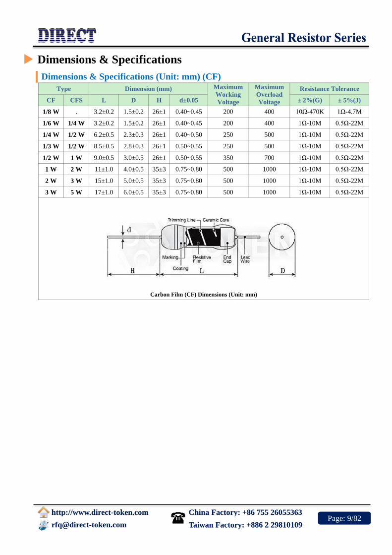
Dimensions & Specifications (Unit: mm) (CF)
Type Dimension (mm) Maximum
Working
Voltage
Maximum
Overload
Voltage
Resistance Tolerance
CF CFS L D H d±0.05 ± 2%(G) ± 5%(J)
1/8 W . 3.2±0.2 1.5±0.2 26±1 0.40~0.45 200 400 10Ω-470K 1Ω-4.7M
1/6 W 1/4 W 3.2±0.2 1.5±0.2 26±1 0.40~0.45 200 400 1Ω-10M 0.5Ω-22M
1/4 W 1/2 W 6.2±0.5 2.3±0.3 26±1 0.40~0.50 250 500 1Ω-10M 0.5Ω-22M
1/3 W 1/2 W 8.5±0.5 2.8±0.3 26±1 0.50~0.55 250 500 1Ω-10M 0.5Ω-22M
1/2 W 1 W 9.0±0.5 3.0±0.5 26±1 0.50~0.55 350 700 1Ω-10M 0.5Ω-22M
1 W 2 W 11±1.0 4.0±0.5 35±3 0.75~0.80 500 1000 1Ω-10M 0.5Ω-22M
2 W 3 W 15±1.0 5.0±0.5 35±3 0.75~0.80 500 1000 1Ω-10M 0.5Ω-22M
3 W 5 W 17±1.0 6.0±0.5 35±3 0.75~0.80 500 1000 1Ω-10M 0.5Ω-22M
Carbon Film (CF) Dimensions (Unit: mm)

China Factory: +86 755 26055363
http://www.direct-token.com
[email protected] Taiwan Factory: +886 2 29810109 Page: 10/82
Electrical Performance
Electrical Performance (CF)
Test Items Condition Spec
Operating Temp.range -55℃ ~ +155℃
Short Time Over Load 2.5 Times of rated voltage for 5sec. ± 1%
Load Life 70 ℃ on-off cycle 1,000hrs. ± 5%
Moisture-Proof Load Life 40 ℃ 95% RH on-off cycle 1,000hrs ± 5%
Soldering After Resistance 350 ℃ for 3sec. ± 0.5%
Temperature Cycle -30 ℃~85 ℃ 5cycles ± 2%
Resistance Temperature Coefficient
1Ω~22KΩ
22KΩ~510KΩ
510KΩ~1MΩ
1MΩ~2.2MΩ
2.2MΩ~5.1MΩ
± 300PPM / ℃
± 450PPM / ℃
± 800PPM / ℃
± 1000PPM / ℃
± 1400PPM / ℃
Order Codes
Order Codes (CF)
CF 0.125W 100R J TB
Part Number
CF
CFS
Rated Power
(W)
Resistance Value (Ω)
1R 1Ω
10R 10Ω
100R 100Ω
10K 10KΩ
10M 10MΩ
22M 22MΩ
Resistance Tolerance
(%)
G ±2%
J ±5%
Package
TB Taping Box

China Factory: +86 755 26055363
http://www.direct-token.com
[email protected] Taiwan Factory: +886 2 29810109 Page: 11/82
Light Dependent Resistors (PGM)
Product Introduction
Features :
Quick Response
Reliable Performance
Epoxy or hermetical package
Good Characteristic of Spectrum
Applications :
Photoswitch
Photoelectric Control
Auto Flash for Camera
Electronic Toys, Industrial Control
The cadmium sulfide (CdS) or light dependent resistor (LDR)
whose resistance is inversely dependent on the amount of light
falling on it is known by many names including the photo
resistor, photoresistor, photoconductor, photoconductive cell, or
simply the photocell.
A typical structure for a photoresistor uses an active
semiconductor layer that is deposited on an insulating substrate.
The semiconductor is normally lightly doped to enable it to have
the required level of conductivity. Contacts are then placed either
side of the exposed area.
The photo-resistor, CdS, or LDR finds many uses as a low cost photo sensitive element and was used
for many years in photographic light meters as well as in other applications such as smoke, flame and
burglar detectors, card readers and lighting controls for street lamps.
Providing design engineers with an economical CdS or LDR with high quality performance, Direct
Electronics now offers commercial grade PGM photoresistor. Designated the PGM Series, the
photoresistors are available in 5mm, 12mm and 20mm sizes, the conformal epoxy or hermetical
package offer high quality performance for applications that require quick response and good
characteristic of spectrum.
Direct has been designing and manufacturing high performance light dependent resistors for decades.
Our product offerings are extensive and our experience with custom photoresistor is equally extensive.
Contact us with your specific needs. For more information, please link to Direct official website
"General Purpose Resistors".
Light-Dependent Photoresistors for Sensor Applications.

China Factory: +86 755 26055363
http://www.direct-token.com
[email protected] Taiwan Factory: +886 2 29810109 Page: 12/82
Terminology
Terminology (PGM) Light Resistance :
Measured at 10 lux with standard light A (2854K-color temperature) and 2hr. preillumination at 400-600
lux prior testing.
Dark Resistance :
Measured at 10th seconds after closing 10 lux.
Gamma characteristic :
Under 10 lux and 100 lux and given by
γ = log(R10/R100) / log(100/10) = log(R10/R100)
R10, R100: resistance at 10 lux and 100 lux.
The tolerance of γ is ±0.1.
Pmax :
Max. power dissipation at ambient temperature of 25℃.At higher ambient temperature,the maximum
power permissible may be lowered.
Vmax :
Max. voltage in darkness that may be applied to the device continuously.
Spectral peak :
Spectral sensitivity of photoresistors depends on the wavelength of light they are exposed to and in
accordance with figure 'Spectral Response'. The tolerance of spectral peak is ±50nm.
CdS Photoresistor (Light Dependent Resistors) - PGM Series
CdS Photoresistors (PGM) Spectral Response
China Factory: +86 755 26055363
http://www.direct-token.com
[email protected] Taiwan Factory: +886 2 29810109 Page: 13/82
Physical and Environmental Characteristics
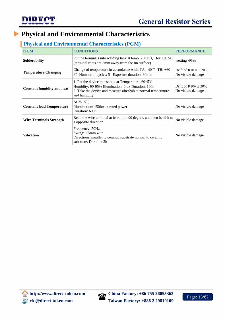
Physical and Environmental Characteristics (PGM)
ITEM CONDITIONS PERFORMANCE
Solderability Put the terminals into welding tank at temp. 230±5℃ for 2±0.5s
(terminal roots are 5mm away from the tin surface). wetting>95%
Temperature Changing Change of temperature in accordance with: TA: -40℃ TB: +60
℃ Number of cycles: 5 Exposure duration: 30min
Drift of R10 = ± 20%
No visible damage
Constant humidity and heat
1. Put the device in test box at Temperature: 60±5℃
Humidity: 90-95% Illumination: 0lux Duration: 100h
2. Take the device and measure after24h at normal temperature
and humidity.
Drift of R10= ± 30%
No visible damage
Constant load Temperature
At 25±5℃
Illumination: 150lux at rated power
Duration: 600h
No visible damage
Wire Terminals Strength Bend the wire terminal at its root to 90 degree, and then bend it to
a opposite direction. No visible damage
Vibration
Frequency: 50Hz
Swing: 1.5mm with
Directions: parallel to ceramic substrate normal to ceramic
substrate. Duration:2h
No visible damage
China Factory: +86 755 26055363
http://www.direct-token.com
[email protected] Taiwan Factory: +886 2 29810109 Page: 14/82
Configurations & Dimensions
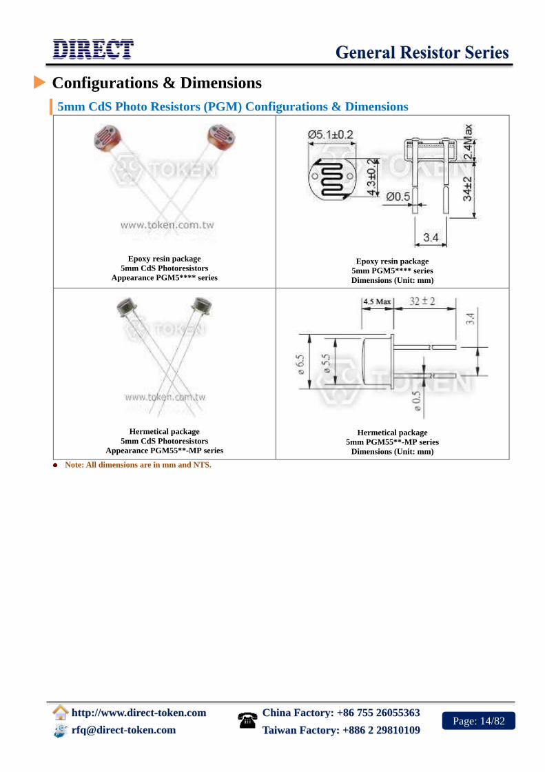
5mm CdS Photo Resistors (PGM) Configurations & Dimensions
Epoxy resin package
5mm CdS Photoresistors
Appearance PGM5**** series
Epoxy resin package
5mm PGM5**** series
Dimensions (Unit: mm)
Hermetical package
5mm CdS Photoresistors
Appearance PGM55**-MP series
Hermetical package
5mm PGM55**-MP series
Dimensions (Unit: mm)
Note: All dimensions are in mm and NTS.

China Factory: +86 755 26055363
http://www.direct-token.com
[email protected] Taiwan Factory: +886 2 29810109 Page: 15/82
PGM5**** Electronics Characteristics
Epoxy resin package 5mm CdS (PGM5****) Electronics Characteristics
Model Vmax
(VDC)
Pmax
(mW)
Ambient
Temp
(℃)
Spectral
Peak
(nm)
Photo
Resistance
(10Lx)
(KΩ)
Dark
Resistance
(MΩ)min
γ
min
Response Time
(ms)
Rise Decay
PGM5506 100 90 -30 ~ +70 540 2 ~ 6 0.15 0.6 30 40
PGM5516 100 90 -30 ~ +70 540 5 ~ 10 0.2 0.6 30 40
PGM5526 150 100 -30 ~ +70 540 8 ~ 20 1.0 0.6 20 30
PGM5537 150 100 -30 ~ +70 540 16 ~ 50 2.0 0.7 20 30
PGM5539 150 100 -30 ~ +70 540 30 ~ 90 5.0 0.8 20 30
PGM5549 150 100 -30 ~ +70 540 45 ~ 140 10.0 0.8 20 30
PGM5616D 150 100 -30 ~ +70 560 5 ~ 10 1.0 0.6 20 30
PGM5626D 150 100 -30 ~ +70 560 8 ~ 20 2.0 0.6 20 30
PGM5637D 150 100 -30 ~ +70 560 16 ~ 50 5.0 0.7 20 30
PGM5639D 150 100 -30 ~ +70 560 30 ~ 90 10.0 0.8 20 30
PGM5649D 150 100 -30 ~ +70 560 50 ~ 160 20.0 0.8 20 30
PGM5659D 150 100 -30 ~ +70 560 150 ~ 300 20.0 0.8 20 30
PGM55** Electronics Characteristics
Hermetical package 5mm CdS (PGM55**-MP) Electronics Characteristics
Model Vmax
(VDC)
Pmax
(mW)
Ambient
Temp
(℃)
Spectral
Peak
(nm)
Photo
Resistance
(10Lx)
(KΩ)
Dark
Resistance
(MΩ)min
γ
min
Response Time
(ms)
Rise Decay
PGM5506-MP 100 90 -30 ~ +70 540 2 ~ 6 0.15 0.6 30 40
PGM5516-MP 100 90 -30 ~ +70 540 5 ~ 10 0.2 0.6 30 40
PGM5526-MP 150 100 -30 ~ +70 540 8 ~ 20 1.0 0.6 20 30
PGM5537-MP 150 100 -30 ~ +70 540 16 ~ 50 2.0 0.7 20 30
PGM5539-MP 150 100 -30 ~ +70 540 30 ~ 90 5.0 0.8 20 30
PGM5549-MP 150 100 -30 ~ +70 540 45 ~ 140 10.0 0.8 20 30

China Factory: +86 755 26055363
http://www.direct-token.com
[email protected] Taiwan Factory: +886 2 29810109 Page: 16/82
Configurations & Dimensions
12mm Cds Photo Resistors (PGM) Configurations & Dimensions
Epoxy resin package
12mm CdS Photo Resistors Appearance PGM12** series
Epoxy resin package
12mm Cds PGM12** series Dimensions (Unit: mm)
Hermetical package
12mm CdS Photo Resistors Appearance PGM12**-MP series
Hermetical package
12mm Cds PGM12**-MP series Dimensions (Unit: mm)
Note : All dimensions are in mm and NTS.

China Factory: +86 755 26055363
http://www.direct-token.com
[email protected] Taiwan Factory: +886 2 29810109 Page: 17/82
PGM12** Electronics Characteristics
Cds - (PGM12**) Electronics Characteristics
Model Vmax
(VDC)
Pmax
(mW)
Ambient
Temp (℃) Spectral
Peak (nm)
Photo
Resistance
(10Lx)
(KΩ)
Dark
Resistance
(MΩ)min
γ min
Response Time (ms)
Rise Decay
PGM1200 250 250 -30 ~ +70 560 2~5 1.0 0.6 30 40
PGM1201 250 250 -30 ~ +70 560 4~10 2.0 0.7 30 30
PGM1202 250 250 -30 ~ +70 560 8~20 5.0 0.7 30 30
PGM1203 250 250 -30 ~ +70 560 18~50 10 0.8 30 30
PGM1204 250 250 -30 ~ +70 560 45~150 20 0.8 30 30
PGM1205 250 250 -30 ~ +70 560 140~300 20 0.8 30 30
PGM12**-MP Electronics Characteristics
Cds - (PGM12**-MP) Electronics Characteristics
Model Vmax
(VDC)
Pmax
(mW)
Ambient
Temp
(℃)
Spectral
Peak
(nm)
Photo
Resistance
(10Lx)
(KΩ)
Dark
Resistance
(MΩ)min
γ min
Response Time (ms)
Rise Decay
PGM1200-MP 250 250 -30 ~ +70 560 2~5 1.0 0.6 30 40
PGM1201-MP 250 250 -30 ~ +70 560 4~10 2.0 0.7 30 30
PGM1202-MP 250 250 -30 ~ +70 560 8~20 5.0 0.7 30 30
PGM1203-MP 250 250 -30 ~ +70 560 18~50 10 0.8 30 30
PGM1204-MP 250 250 -30 ~ +70 560 45~150 20 0.8 30 30
PGM1205-MP 250 250 -30 ~ +70 560 140~300 20 0.8 30 30

China Factory: +86 755 26055363
http://www.direct-token.com
[email protected] Taiwan Factory: +886 2 29810109 Page: 18/82
Configurations & Dimensions
20mm CDS Photo Resistors (PGM) Configurations & Dimensions
Epoxy resin package
20mm CDS Photo Resistors Appearance PGM20** series
Epoxy resin package
20mm CdS PGM20** series Dimensions (Unit: mm)
Hermetical package
20mm CDS Photo Resistors Appearance PGM20**-PP series
Hermetical package
20mm CdS PGM20**-PP series Dimensions (Unit: mm)
Note: All dimensions are in mm and NTS.
China Factory: +86 755 26055363
http://www.direct-token.com
[email protected] Taiwan Factory: +886 2 29810109 Page: 19/82
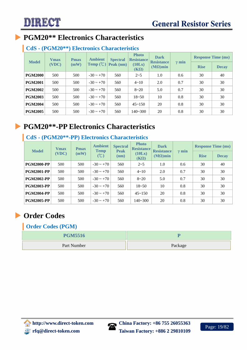
PGM20** Electronics Characteristics
CdS - (PGM20**) Electronics Characteristics
Model Vmax
(VDC)
Pmax
(mW)
Ambient
Temp (℃) Spectral
Peak (nm)
Photo
Resistance
(10Lx)
(KΩ)
Dark
Resistance
(MΩ)min
γ min
Response Time (ms)
Rise Decay
PGM2000 500 500 -30 ~ +70 560 2~5 1.0 0.6 30 40
PGM2001 500 500 -30 ~ +70 560 4~10 2.0 0.7 30 30
PGM2002 500 500 -30 ~ +70 560 8~20 5.0 0.7 30 30
PGM2003 500 500 -30 ~ +70 560 18~50 10 0.8 30 30
PGM2004 500 500 -30 ~ +70 560 45~150 20 0.8 30 30
PGM2005 500 500 -30 ~ +70 560 140~300 20 0.8 30 30
PGM20**-PP Electronics Characteristics
CdS - (PGM20**-PP) Electronics Characteristics
Model Vmax
(VDC)
Pmax
(mW)
Ambient
Temp
(℃)
Spectral
Peak
(nm)
Photo
Resistance
(10Lx)
(KΩ)
Dark
Resistance
(MΩ)min
γ min
Response Time (ms)
Rise Decay
PGM2000-PP 500 500 -30 ~ +70 560 2~5 1.0 0.6 30 40
PGM2001-PP 500 500 -30 ~ +70 560 4~10 2.0 0.7 30 30
PGM2002-PP 500 500 -30 ~ +70 560 8~20 5.0 0.7 30 30
PGM2003-PP 500 500 -30 ~ +70 560 18~50 10 0.8 30 30
PGM2004-PP 500 500 -30 ~ +70 560 45~150 20 0.8 30 30
PGM2005-PP 500 500 -30 ~ +70 560 140~300 20 0.8 30 30
Order Codes
Order Codes (PGM)
PGM5516 P
Part Number
Package

China Factory: +86 755 26055363
http://www.direct-token.com
[email protected] Taiwan Factory: +886 2 29810109 Page: 20/82
Ceramic Housed Cement Resistors
(SQ)
Product Introduction
Features :
Low cost, space saving
RoHS compliant with 100% lead free
Direct mounting on printed circuit board
Circuit board lock-in mounting tabs available
High performance for power required applications
High power to size ratio, Special inorganic potting compound
Ceramic case provide high thermal conductivity in a
fireproof package
Applications :
Power supplies
Voltage dividers
Motor controllers
Automotive applications
Power electronics circuits
Direct electronics offers commercial grade ceramic-housed
power wire wound and film resistors. For medium to high rated
power (2W...50W), SQ resistors provide full electrical insulation
mounted in a ceramic case.
Axial, radial, vertical styles and several mounting techniques of
wire leads or quick disconnects are available from Direct's SQP,
SQM, SQZ, and SQH.
The SQ series power resistors feature ideal specifications for
high volume and high-temperature applications. Frequently used
in power supplies, motor controllers, and automotive applications, these products can be custom
tailored to individual needs.
With the extended resistance range and high-temperature rating, the resistors can be specified for
operation in harsh environments. The SQ series wire wound resistors feature a resistance range from
0.1Ω to 3KΩ, while the SQ series power film resistors have a resistance range of 80Ω to 150KΩ.
Standard tolerances for both devices are to ±5%, with TCRs of ±300ppm/℃ and above. Direct is
equipped to design and produce custom components to meet many design and reliability demands.
Contact us with your specific needs. For more information, please link to Direct official website
"General Purpose Resistors".
Low-cost Ceramic Encased Cement Resistors Suit High
Volumes and High Temperatures.

China Factory: +86 755 26055363
http://www.direct-token.com
[email protected] Taiwan Factory: +886 2 29810109 Page: 21/82
SQP Dim.
Dimensions (SQP)
Type Dimension (mm) Resistance Range (Ω)
SQP W±1 H±1 L±1.5 d±0.05 SQP RS+SQP
2W 7 7 18 0.5~0.6 0.1~82
3W 8 8 22 0.7~0.8 0.1~180 181~33K
5W 10 9 22 0.7~0.8 0.1~180 181~50K
7W 10 9 35 0.7~0.8 0.1~430 431~50K
10W 10 9 48 0.7~0.8 0.1~470 471~50K
15W 12.5 11.5 48 0.7~0.8 0.5~600 601~150K
20W-25W 14 13.5 60 0.7~0.8 0.8~1K 1.1~150K
Cement Ceramic Housed (SQP) Dimensions

China Factory: +86 755 26055363
http://www.direct-token.com
[email protected] Taiwan Factory: +886 2 29810109 Page: 22/82
SQM Dim.
Dimensions (SQM)
Type Dimension (mm) Resistance Range (Ω)
SQM H±1.5 W±1 S±1 SQM RS+SQM
2W 20 12 8 0.1-8.0 81-50K
3W 25 12 8 0.1-180 181-50K
5W 25 13 9 0.1-180 181-50K
7W 39 13 9 0.1-430 431-47K
10W 51 13 12 0.1-470 471-47K
10WS 35 16 12 0.1-430 431-47K
Ceramic Housed (SQM) Dimensions

China Factory: +86 755 26055363
http://www.direct-token.com
[email protected] Taiwan Factory: +886 2 29810109 Page: 23/82
SQT Dim.
Dimensions (SQT)
Type Dimension (mm) Resistance Range (Ω)
SQT H±1.5 W±1 L±1 t±1 SQT RS+SQM
3W 9 10 22 1.5 0.1-180 181-50K
5W 9 10 22 1.5 0.1-180 181-50K
7W 9 10 35 3.0 0.1-430 431-47K
10W 9 10 48 3.0 0.1-470 471-47K
Cement Ceramic Encased (SQT) Dimensions

China Factory: +86 755 26055363
http://www.direct-token.com
[email protected] Taiwan Factory: +886 2 29810109 Page: 24/82
SQH Dim.
Dimensions (SQH)
Type Dimension (mm) Resistance Range (Ω) Max
Working
Voltage SQH W±1 H±1 L±1.5 P±1 H1±1 D±0.5 P1±0.2 P2±0.2 SQH RS+SQH
10W 10 9 48 32 21 5 2.5 2 0.1~500 500~50K 500V
15W 12.5 11.5 48 32 21 5 2.5 2 1~1K 1K~150K 600V
20W 14.5 13.5 60 43 24 6 3.0 2.5 1~2K 2K~150K 700V
30W 19 19 75 56 29 6 3.0 2.5 1~2K
700V
40W 19 19 90 67 29 6 3.0 2.5 2~3K
700V
50W 19 19 90 67 29 6 3.0 2.5 2~3K
700V
Cement Ceramic Encased (SQH) Dimensions

China Factory: +86 755 26055363
http://www.direct-token.com
[email protected] Taiwan Factory: +886 2 29810109 Page: 25/82
SQZ Dim.
Dimensions (SQZ)
Type Dimension (mm) Resistance Range (Ω)
SQZ L±1.5 W±1 H±1 P±1.5 P1 P2 P3 P4 H1±1 H2±1 SQZ RS+SQZ
5W 25(28) 10 10 9.5(15) 4.2 2 5 1.5 25 10.5 0.1-130 131-50K
7W 36 10 10 20 4.2 2 5 1.5 25 10.5 0.1-430 431-50K
10W 48 10 10 32 4.2 2 5 1.5 25 10.5 0.2-470 471-50K
15W 48 12.5 12 32 4.2 2 5 1.5 26 10.5 1-600 601-150K
20.25W 60 15 13 42 7 6 10 2.7 36 15.0 1-1K 1.1K-150K
Cement Ceramic Encased (SQZ) Dimensions

China Factory: +86 755 26055363
http://www.direct-token.com
[email protected] Taiwan Factory: +886 2 29810109 Page: 26/82
Electrical Performance
Electrical Performance (SQ)
TEST ITEMS CONDITION SPEC.
Resistance Temp Coeff. -30℃~ 200℃ ±300ppm / ℃
Short Time Over Load 2.5 times of rated wattage for 5 sec. ±2 %
Rated Load Rated wattage for 30 min. ±1 %
Voltage Withstanding 800 v AC 1 min. no charge
Temp. Cycle -30℃~ 85℃for 5 cycles ±1 %
Load Life 70℃on-off cycle 1000hrs. ±5 %
Moisture-proof Load Life 40℃95% RH on-off cycle 500 hrs. ±5 %
Incombustibility 16 times of rated wattage for 5 min. not flamed
Material Specifications
Material Specifications (SQ) Core :
High purity grade alumina ceramic rod.
Terminals :
Tin/lead plated (Lead (Pb)-free will be 100 % tin).
Body :
Steatite ceramic case with inorganic potting compound.
Element :
Copper-nickel alloy, nickel-chrome alloy, resistive wirewound or power film depending on resistance
value.
Order Codes
Order Codes (SQ)
SQP 5W 100R J Bulk
Part Number
SQP
SQM
SQT
SQH
SQZ
Rated Power
(W)
Resistance Value (Ω)
0R1 0.1Ω
100R 100Ω
1K 1KΩ
100K 100KΩ
Resistance Tolerance
(%)
J ±5%
Package

China Factory: +86 755 26055363
http://www.direct-token.com
[email protected] Taiwan Factory: +886 2 29810109 Page: 27/82
Carbon Composition Resistors
(CCR)
Product Introduction
Features :
Low inductance
Solid rod carbon composition
Power rating 1/4W and 2W
Resistance range 1.8Ω ~ 22KΩ
Resistance tolerance J(±5%), K(±10%) and M(±20%)
High pulse withstanding and high energy capability
Products with Pb-free Terminations and RoHS compliant
Applications :
Strobe Lighting
High Power Lighting
Medical defibrillators
Welding, Automotive
Inrush Current Limiting
High Voltage Power Supplies
Protection (e.g. Discharge Circuits,
Surge Protection)
The high pulse withstanding capability of the CCR series of carbon
composition resistors from Direct Electronics offers designers a compact
solution for applications involving high voltages and high-energy pulses.
Though, many resistor manufacturers claim to offer carbon composition
replacements. However, these wire wound or thick film alternatives do
not fully match the pulse performance and low inductance of carbon
composition.
Direct's CCR series now offers the industry a carbon composition
resistor made up of a solid rod of conductive composite material, the chemical composition of which is
altered to produce different resistance values.
The main advantage of carbon composition is their pulse handling capability. This is due to the fact
that the entire rod conducts and so the thermal mass is far higher, which results in a higher energy
capability. Due to the need for higher peak voltages, the CCR range is perfect for vehicle ignition
system applications, medical monitoring equipment and as output resistors in defibrillators.
The standard carbon composition CCR resistor offers a power rating of 1/4W, 1/2W, 1W and 2W at 25
℃ and is made up of a solid rod of conductive composition material, which can be altered to produce
different resistance values. With a typical resistance range of 1.8Ω ~ 22KΩ, resistance tolerance is
J(±5%), K(±10%) and M(±20%). Resistors with 5%, 10% and 20% tolerance have four bands
indicating value and tolerance in accordance with IEC62.
Our custom solutions are designed to address your need for technical and economic success in a timely
manner. Contact us with your specific needs. For more information, please link to Direct official
website "General Purpose Resistors".
High pulse withstanding carbon composition resistors
handle big peaks and pulses.

China Factory: +86 755 26055363
http://www.direct-token.com
[email protected] Taiwan Factory: +886 2 29810109 Page: 28/82
Dimensions
Dimensions (Unit: mm) (CCR)
Type Power Rating L Φ D H Φ d
CCR 1/4W 6.3 +1.0
2.3±0.3 27±2 0.60±0.02 -1.0
CCR 1/2W 9.5 +0.5
3.5±0.3 27±2 0.70±0.02 -1.5
CCR 1W 15 +1.5
6.0±0.3 28±2 0.80±0.02 -0.5
CCR 2W 18 +0.5
8.0±0.3 27±2 1.00±0.02 -1.5
Carbon Composition (CCR) Dimensions (Unit: mm)
Ratings Specifications
Ratings Specifications (CCR)
Type Power
Rating
Resistance
Range
Tolerance
E12,E24
Max Working
voltage
Max overload
Voltage
Rated Ambient
Temp.
Operating
Temp. Range
CCR 1/4W 2.2Ω ~ 12MΩ
J(±5%)
K±10%
M±20%
250V 400V +70℃ -55℃ ~ +125℃
CCR 1/2W 2.2Ω ~ 22MΩ 350V 700V +70℃ -55℃ ~ +125℃
CCR 1W 2.2Ω ~ 22KΩ 500V 1000V +70℃ -55℃ ~ +125℃
CCR 2W 1.8Ω ~ 10KΩ 500V 1000V +70℃ -55℃ ~ +125℃
Rated Voltage = √𝐏𝐨𝐰𝐞𝐫 𝐑𝐚𝐭𝐢𝐧𝐠 ∗ 𝐑𝐞𝐬𝐢𝐬𝐭𝐚𝐧𝐜𝐞 𝐕𝐚𝐥𝐮𝐞 or Max. Working voltage, whichever is lower.

China Factory: +86 755 26055363
http://www.direct-token.com
[email protected] Taiwan Factory: +886 2 29810109 Page: 29/82
Derating Curve
Derating Curve (CCR)
(CCR) Derating Curve

China Factory: +86 755 26055363
http://www.direct-token.com
[email protected] Taiwan Factory: +886 2 29810109 Page: 30/82
Performance
Performance (CCR)
Description Performance Requirements Test Method
Resistance
Temperature
Coefficient
Resistance Range
Maximum Resistance Value
Change %
Test Temperature
+20℃ /-40℃ /+20℃ /+100℃ /+20℃
-40~+20℃ +20~+100℃
<1KΩ ±6.5% ±5.0%
1.1KΩ ~10KΩ ±10% ±6.0%
11KΩ ~100KΩ ±13% ±7.5%
11KΩ ~1MΩ ±15% ±10%
1.1MΩ ~10MΩ ±20% ±15%
>11MΩ ±25% ±20%
Short-time Overload Δ R≤±2.5% Rate Voltage*2.5 or maximum overload
voltage (the lower)5sec.
With Standing
Voltage No flashover or breakdown 2times maximum working voltage 1 minute
Terminal
Strength
Pulled
ΔR≤±2% No visible damage
Load 10N 10s
Winded Load 10N 4*90°
Twisted 3*360° in opposite direction
Resistance to
vibration No visible damage 10~50Hz 3 direction 2 hours each
Solder-heat Resistance ΔR≤±5% Marks legible, no visible damage 350℃ 4mm from the body,3 seconds
Solderability At least 95% if the dipping surface must be covered
by new solder, no flaws gathered. 235℃ 2mm from the body,2 seconds
Temperature Cycle ΔR≤±2%
No visible damage -40℃(30min.)/85℃(30min.)5 cycles
Humidity ΔR≤±10% No visible damage 40℃ 95% RH 240 hours
Load Life ΔR≤±10%
No visible damage, marks legible
Rated voltage or maximum working
voltage, 1.5 hours on, 0.5 hours off, 40℃
1000 hours
Order Codes
Order Codes (CCR)
CCR 1/2W 120R K P
Part Number
CCR
Rated Power
(W)
Resistance Value (Ω)
2R2 2.2Ω
120R 120Ω
1M2 1.2MΩ
22M 22MΩ
Resistance Tolerance
(%)
J ±5%
K ±10%
M ±20
Package
P Bulk

China Factory: +86 755 26055363
http://www.direct-token.com
[email protected] Taiwan Factory: +886 2 29810109 Page: 31/82
Fusible Resistors (FRN, FKN, FSQ)
Product Introduction
Features :
Low Cost
Low Noise
Reduced numbers of parts used in circuits
Products with Pb-free Terminations and RoHS
compliant
Applications :
Telecommunications
Household appliances
Inrush Pulse protection
Lightning strike protection
Input protection for small power supplies and
battery chargers
Designers of small power supplies and battery chargers for consumer
products can benefit from a fusible resistor with superior lightning
strike and pulse abilities in a cost effective package.
Direct Electronics offers a combination resistor/fuses series of
metal/carbon film fusible resistor (FRN), wire wound fuse resistor
(FKN) and cement encased fusing resistors (FSQ). Direct offers
fusible FRN series a low-cost alternative to traditional solutions for
applications that require surge protection.
The robust ceramic encased cement resistor (FSQ) and wire wound resistor (FKN) are ideal for power
supply applications across the telecoms, military and industrial markets which require a replacement
for carbon composition resistors within the circuit design.
As part of the Direct input protection range, this resistor provides a key fusible solution and is
completely customizable to suit the individual application design requirements. Key design engineers
with a need for a robust resistor, will find the FRN, FKN and FSQ series are a multifaceted product,
providing comparable pulse performance with added fusing capabilities.
Our custom solutions are designed to address your need for technical and economic success in a timely
manner. Contact us with your specific needs. Or link to Direct official website "General Purpose
Resistors" for more information.
Fusible resistor features best of both worlds.

China Factory: +86 755 26055363
http://www.direct-token.com
[email protected] Taiwan Factory: +886 2 29810109 Page: 32/82
Specifications (FRN)
Specifications & Dimensions (Unit: mm) Thin-Film Fusible Resistor (FRN)
Type Rated Wattage Dimension (mm)
Resistance Range Dielectric Withstanding Voltage L ± 1.5 D ± 1 H ± 3 d ± 0.05
FRN
1/4W
1/2W
1W
2W
3W
6
6
9
11
15
2.3
2.3
3.0
4.0
5,0
26
26
26
26
35
0.40~0.50
0.50~0.55
0.50~0.55
0.75~0.80
0.75~0.80
0.22Ω~100KΩ
0.22Ω~100KΩ
0.22Ω~100KΩ
0.3Ω~100KΩ
0.3Ω~100KΩ
300V
300V
350V
500V
500V
Thin-Film Fusible Resistor (FRN) Dimensions (Unit: mm)

China Factory: +86 755 26055363
http://www.direct-token.com
[email protected] Taiwan Factory: +886 2 29810109 Page: 33/82
Specifications (FKN)
Specifications & Dimensions (Unit: mm) Wire wound Fuse Resistor (FKN)
Type Rated Wattage Dimension (mm)
Resistance Range Dielectric Withstanding Voltage L ± 1.5 D ± 1 H ± 3 d ± 0.05
FKN
1W
2W
3W
5W
6W
9
11
15
17
24
4.5
5.0
5.5
6.5
8.5
26
26
35
35
38
0.50~0.55
0.75~0.80
0.75~0.80
0.75~0.80
0.75~0.80
0.1Ω~22Ω
0.1Ω~60Ω
0.1Ω~100Ω
0.2Ω~200Ω
0.3Ω~250Ω
500V
500V
500V
500V
500V
Wirewound Fuse Resistor (FKN) Dimensions (Unit: mm)
Specifications (FSQ)
Specifications & Dimensions (Unit: mm) Cement Fusing Resistor (FSQ)
Type Rated
Wattage
Dimension (mm) Resistance
Range
Dielectric Withstanding
Voltage L ± 1.5 H ± 0.5 W ± 0.5 H ± 3 d ± 0.05
FSQ
2W
3W
5W
7W
10W
18
22
22
35
48
7
8
9
9
9
7
8
10
10
10
35
35
35
35
35
0.50~0.55
0.75~0.80
0.75~0.80
0.75~0.80
0.75~0.80
0.1Ω~22Ω
0.1Ω~120Ω
0.2Ω~120Ω
0.3Ω~250Ω
0.3Ω~500Ω
1000V
1000V
1000V
1000V
1000V
Ceramic Encased Cement Fusing Resistor (FSQ) Dimensions (Unit: mm)

China Factory: +86 755 26055363
http://www.direct-token.com
[email protected] Taiwan Factory: +886 2 29810109 Page: 34/82
Characteristics
Electrical Characteristics (FRN, FKN, FSQ)
Test Items Condition Spec.
Operating Temp. -30℃~155℃
Resistance Temp. Coeff. -30℃~150℃ ± 200PPM / ℃
Short Time Overload 2 times of rated voltage for 5 sec. ± 2 %
Temp. Cycle -30℃~85℃ for 5 cycles ± 1 %
Load Life 25℃ on-off cycle 1,000 hrs. ± 5 %
Moisture-Proof Load Life 40℃ 95℃ RH on-off cycle 1,000 hrs. ± 5 %
Solder Pot 270℃ for 3 sec. ± 1 %
Incombustibility 16 times of rated wattage for 5 min. not flamed
Fusing Characteristics (FRN, FKN, FSQ)
POWER WATTAGE FUSING TIME
16 × Rated Wattage Within 2 min
24 × Rated Wattage Within 1 min
32 × Rated Wattage Within 30 sec.

China Factory: +86 755 26055363
http://www.direct-token.com
[email protected] Taiwan Factory: +886 2 29810109 Page: 35/82
Application Notes
Application Notes of Fusible Resistors (FRN, FKN, FSQ)
For fusible resistors, unlike fuses, fusing performance is given in terms of power rather than current.
The power can be calculated:
Power = Amperes 2 × Ohms
Fusing Device Application Notes
When using, it shall be made sure that the overload conditions at unusual moments lie within the fusing
territory.
Consult with Direct in advance when overloaded higher than the rated voltage under an ordinary situation
since such an overload may store up damages on resistors.
Use at the maximum open-circuit voltage or lower as an arc phenomenon may arise when high voltage is
applied again after fusing by an over current.
Consult with us for the maximum open- circuit voltage because it varies with applications.
Order Codes
Order Codes (FRN, FKN, FSQ)
FRN 1/2W 0.47R J TB
Part Number
FRN
FKN
FSQ
Rated Power
(W)
Resistance Value (Ω)
R47 0.47Ω
47R 47Ω
470R 470Ω
4K7 4.7KΩ
47K 47KΩ
Resistance Tolerance
(%)
J ±5%
Package
P Bulk
TB Taping Box

China Factory: +86 755 26055363
http://www.direct-token.com
[email protected] Taiwan Factory: +886 2 29810109 Page: 36/82
Metal Oxide Resistors (RSS, RSN)
Product Introduction
Features :
Tolerances: G (±2%), J (±5%)
Lead (Pb)-free and RoHS compliant
Power wattages up to 10W at + 25 ℃
Operating temperature range: -55℃~200℃
Axial leaded type, high power at compact sizes
Replace carbon composition components in some
applications
Applications :
Ballasts
Amplifiers
Power supplies
Telecommunications
Household appliances
Automotive, Computer, Instrumentation
Now available from Direct Electronics is a new range of highly
stable and reliable metal oxide resistors providing high power in a
small package with various forming styles and different leads for
different applications.
New RS series resistors are ideal for pulse applications in adverse
conditions and are available in different sizes with power ratings
of 0.5W to 10W for a power voltage range from 200V to 850V.
Highly temperature resistant the devices feature a resistance range
from 10Ω to 47KΩ.
RS series resistors are available in various forming styles and different leads for different applications
like power supplies, amplifiers, household appliances and ballasts.
Manufactured by depositing a homogeneous oxide film of metal alloy onto a high-grade ceramic body,
the metal oxide resistors are coated with a nonflammable lacquer providing mechanical, electrical and
climatic protection.
The devices come packaged in ammo pack boxed or tape and reel format. All RS Series devices are
RoHS-compliant, and compatible with high temperature soldering processes normally employed for
lead free solders.
Contact us with your specific needs. For more information, please link to Direct official website
"General Purpose Resistors".
Metal Oxide Resistors on the pulse in various forming
styles for different applications.

China Factory: +86 755 26055363
http://www.direct-token.com
[email protected] Taiwan Factory: +886 2 29810109 Page: 37/82
Specifications & Dimensions
Specifications & Dimensions (Unit: mm) (RSS, RSN)
Type Dimensions (Unit: mm) Resistance
Range
Tolerance
E24
MAX Working
Voltage
Dielectric
Withstanding
Voltage
RSS RSN L D H d ± 0.05 (Ω) (%) RSS RSN RSS RSN
1/2W 1/4W 6.0± 0.3 2.3 ± 0.3 26 ± 1 0.40~0.50 10Ω ~ 22KΩ ±2%, ±5% 200V 300V 400V 500V
1W 1/2W 9.0± 0.5 3.0 ± 0.5 26 ± 1 0.50~0.55 10Ω ~ 33KΩ ±2%, ±5% 250V 350V 500V 600V
2W 1W 11 ± 1.0 4.0 ± 0.5 26 ± 3 0.75~0.80 10Ω ~ 47KΩ ±2%, ±5% 300V 350V 600V 700V
3W 2W 15 ± 1.0 5.0 ± 0.5 35 ± 3 0.75~0.80 10Ω ~ 47KΩ ±2%, ±5% 350V 350V 700V 700V
5W 3W 17± 1.0 6.0 ± 0.5 35 ± 3 0.75~0.80 10Ω ~ 47KΩ ±2%, ±5% 350V 500V 700V 1000V
- 5W 24 ± 1.0 8.0 ± 0.5 38 ± 3 0.75~0.80 10Ω ~ 47KΩ ±2%, ±5% 500V 700V 800V 1000V
7W 6W 24 ± 1.0 8.0 ± 0.5 38 ± 3 0.75~0.80 10Ω ~ 47KΩ ±2%, ±5% 500V 700V 800V 1000V
10W 7W 41 ± 1.0 8.0 ± 0.5 38 ± 3 0.75~0.80 10Ω ~ 47KΩ ±2%, ±5% 750V 850V 850V 1000V
10W 53 ± 1.0 8.0 ± 0.5 38 ± 3 0.75~0.80 10Ω ~ 47KΩ ±2%, ±5% 750V 850V 850V 1000V
Metal Oxide Film (RSS, RSN) Dimensions (Unit: mm)
China Factory: +86 755 26055363
http://www.direct-token.com
[email protected] Taiwan Factory: +886 2 29810109 Page: 38/82
Electrical Performance
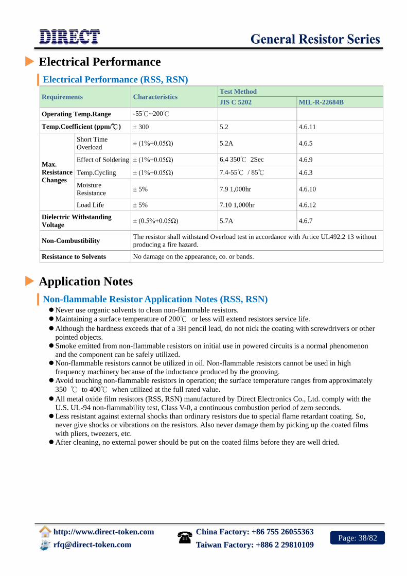
Electrical Performance (RSS, RSN)
Requirements Characteristics Test Method
JIS C 5202 MIL-R-22684B
Operating Temp.Range -55℃~200℃
Temp.Coefficient (ppm/℃) ± 300 5.2 4.6.11
Max.
Resistance
Changes
Short Time
Overload ± (1%+0.05Ω) 5.2A 4.6.5
Effect of Soldering ± (1%+0.05Ω) 6.4 350℃ 2Sec 4.6.9
Temp.Cycling ± (1%+0.05Ω) 7.4-55℃ / 85℃ 4.6.3
Moisture
Resistance ± 5% 7.9 1,000hr 4.6.10
Load Life ± 5% 7.10 1,000hr 4.6.12
Dielectric Withstanding
Voltage ± (0.5%+0.05Ω) 5.7A 4.6.7
Non-Combustibility The resistor shall withstand Overload test in accordance with Artice UL492.2 13 without
producing a fire hazard.
Resistance to Solvents No damage on the appearance, co. or bands.
Application Notes
Non-flammable Resistor Application Notes (RSS, RSN) Never use organic solvents to clean non-flammable resistors.
Maintaining a surface temperature of 200℃ or less will extend resistors service life.
Although the hardness exceeds that of a 3H pencil lead, do not nick the coating with screwdrivers or other
pointed objects.
Smoke emitted from non-flammable resistors on initial use in powered circuits is a normal phenomenon
and the component can be safely utilized.
Non-flammable resistors cannot be utilized in oil. Non-flammable resistors cannot be used in high
frequency machinery because of the inductance produced by the grooving.
Avoid touching non-flammable resistors in operation; the surface temperature ranges from approximately
350 ℃ to 400℃ when utilized at the full rated value.
All metal oxide film resistors (RSS, RSN) manufactured by Direct Electronics Co., Ltd. comply with the
U.S. UL-94 non-flammability test, Class V-0, a continuous combustion period of zero seconds.
Less resistant against external shocks than ordinary resistors due to special flame retardant coating. So,
never give shocks or vibrations on the resistors. Also never damage them by picking up the coated films
with pliers, tweezers, etc.
After cleaning, no external power should be put on the coated films before they are well dried.
China Factory: +86 755 26055363
http://www.direct-token.com
[email protected] Taiwan Factory: +886 2 29810109 Page: 39/82
Order Codes
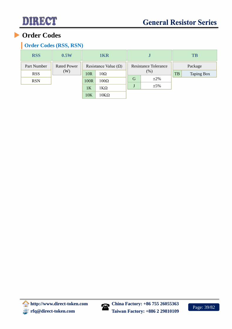
Order Codes (RSS, RSN)
RSS 0.5W 1KR J TB
Part Number
RSS
RSN
Rated Power
(W)
Resistance Value (Ω)
10R 10Ω
100R 100Ω
1K 1KΩ
10K 10KΩ
Resistance Tolerance
(%)
G ±2%
J ±5%
Package
TB Taping Box

China Factory: +86 755 26055363
http://www.direct-token.com
[email protected] Taiwan Factory: +886 2 29810109 Page: 40/82
Precision Resistors (MF)
Product Introduction
Features :
Low cost, low noise, operating temperature range
-55℃ ~ 155℃
Precision tighted tolerance available in ±0.1%,
±0.25%, ±0.5%, ±1%
Pure tin plating provides compatibility with lead
(Pb)-free and lead containing soldering processes
Applications :
Telecom
Test and measurement
All general purpose applications
Direct offers a low-cost alternative commercial metal film
resistor for precision applications. The MF series offers tight
tolerances and low TCRs over a wide resistance range and are
suitable for applications where long-term stability is paramount.
The MF is available in a resistance range of 10Ω to 1MΩ with a
standard resistance tolerance of ±1% and a temperature
coefficient of resistance (TCR) of +15/-25ppm/℃, although
other tolerances and TCRs are available.
The resistance element in these devices is a precisely controlled
thin film of metal alloy deposited on a high quality alumina rod. Plated caps are force-fitted before the
assembly is trimmed using advanced trimming techniques to ensure excellent performance and low
electrical noise.
Leads are welded to the end caps prior to the resistor being coated with epoxy, and color band marking
applied. A variety of standard lead forms are available for use where auto-insertion is not available or
practical. This gives the advantage of the value being shown, even if the resistor is machine preformed
or auto-inserted.
The MF is RoHS compliant with 100% lead free; Contact us with your specific needs. For more
information, please link to Direct official website "General Purpose Resistors".
Precision metal-film resistors for low-cost uses.

China Factory: +86 755 26055363
http://www.direct-token.com
[email protected] Taiwan Factory: +886 2 29810109 Page: 41/82
Dimensions & Specifications
Dimensions & Specifications (Unit: mm) (MF)
STYLE MIL
STYLE
POWER
RATING(W) DIMENSION (mm)
MAX WORKING
VOLTAGE
MAX OVERLOAD
VOLTAGE
RN RNS L D H d ± 0.05 RN RNS RN RNS
MF - 12 RN-50 1/8W 1/4W 3.2±
0.2
1.5 ±
0.2
26 ±
1.0 0.40~0.45 200 150 400 300
MF - 25 RN-55 1/4W 1/2W 6.0 ±
0.3
2.3 ±
0.3
26 ±
1.0 0.40~0.50 250 200 500 400
MF - 50 RN-60 1/2W 1W 9.0 ±
0.5
3.0 ±
0.5
26 ±
1.0 0.50~0.55 350 250 700 500
MF - 100 RN-65 1W 2W 11 ±
1.0
4.0 ±
0.5
35 ±
3.0 0.75~0.80 500 300 1000 600
MF - 200 RN-70 2W 3W 15 ±
1.0
5.0 ±
0.5
35 ±
3.0 0.75~0.80 500 350 1000 700
Metal Film Resistors (MF) Dimensions (Unit: mm)

China Factory: +86 755 26055363
http://www.direct-token.com
[email protected] Taiwan Factory: +886 2 29810109 Page: 42/82
Resistance Range
Resistance Range (MF)
STYLE MIL
STYLE TOLERANCE TC+15-25PPM TC+50PPM TC+100PPM REMARK
MF-12 RN-50
±1%
±0.5%
±0.25%
100Ω-100KΩ
100Ω-100KΩ
100Ω-100KΩ
10Ω-1MΩ 10Ω-1MΩ
* Standard resistance is
10Ω-1MΩ, below or over
this resistance on request.
MF-25 RN-55
±1%
±0.5%
±0.25%
±0.1%
51.1Ω-511KΩ
51.1Ω-511KΩ
100Ω-300KΩ
100Ω-300KΩ
10Ω-1MΩ 10Ω-1MΩ
MF-50 RN-60
±1%
±0.5%
±0.25%
±0.1%
51.1Ω-1KΩ
51.1Ω-1KΩ
100Ω-551KΩ
100Ω-330KΩ
10Ω-1MΩ 10Ω-1MΩ
MF-100 RN-65
±1%
±0.5%
±0.25%
±0.1%
51.1Ω-1KΩ
51.1Ω-1KΩ
100Ω-551KΩ
100Ω-330KΩ
10Ω-1MΩ 10Ω-1MΩ
MF-200 RN-70
±1%
±0.5%
±0.25%
±0.1%
51.1Ω-1KΩ
51.1Ω-1KΩ
100Ω-551KΩ
100Ω-330KΩ
10Ω-1MΩ 10Ω-1MΩ
Electrical Performance
Electrical Performance (MF)
REQUIREMENTS CHARACTERISTICS JIS C 5202 MIL-R-10509F
Operating Temp. Range -55℃ ~ 155℃
Temp Coefficient (℃ ) ±25 ±50 ±100 5.2 4.6.12
Short Time Overload ±(0.5%%+0.05Ω) 5.5 A 4.6.6
Dielectric Withstanding V ±(0.5%+0.05Ω) 5.7 A 4.6.8
Effect of Soldering ±(0.5%+0.05Ω) 6.4 350℃ 3 sec 4.6.10
Temperature Cycling ±(0.5%+0.05Ω) 7.4 4.6.4
Low Temp Operation ±(0.5%+0.05Ω) 4.6.5
Terminal Strength ±(0.5%+0.05Ω) 6.1 4.6.7
Moisture Resistance ±(1%+0.05Ω) 7.9 1,000hr MIL R-22684 4.6.10
Load Life ±(1%+0.05Ω) 7.10 1,000hr 4.6.13
Storage ±(0.2%+0.05Ω) Shelved one year in a room of normal temperature and
humidity

China Factory: +86 755 26055363
http://www.direct-token.com
[email protected] Taiwan Factory: +886 2 29810109 Page: 43/82
Order Codes
Order Codes (MF)
MF-25 1/4W 100R F TB
Part Number
MF
Rated Power
(W)
Resistance Value (Ω)
10R 10Ω
100R 100Ω
1K 1KΩ
1M 1MΩ
Resistance Tolerance
(%)
B ±0.10%
C ±0.25%
D ±0.5%
F ±1.0%
Package
P Bulk
TB Taping Box

China Factory: +86 755 26055363
http://www.direct-token.com
[email protected] Taiwan Factory: +886 2 29810109 Page: 44/82
Thermal Cut-offs Resistors
(FKU, FRU)
Product Introduction
Features :
Miniature size
Radial leaded form
Accurate fusing temperature
Various temperature settings
Current Rating: Up to 10Amp
Products with Pb-free Terminations and RoHS
compliant
Economical by combining both function of a
thermal fuse and a pulse resistor
Applications :
Motors - fans, copiers, washing machines, air
conditioners, compressors.
Electronics - TVs, tape recorders, stereos, video
recorders, fluorescent lamps, transformers, surge
suppressors, computers, telecommunication
equipment.
Appliances - electric blankets, space heaters,
stoves, irons, hair dryers, cookers, toaster ovens,
clothes dryers, toasters, mixers, microwave
ovens, crock pots.
Fast-acting protection device for high-power applications
combines thermal fuse element and resistor on a single substrate.
Direct offers FKU (Wire wound Resistor + Thermal Cut-offs) and
FRU (Metal Oxide Film Resistor + Thermal Cut-offs) two Series,
both are a new concept in thermal fuse technology and are
designed to protect against over-heating in electrical products.
The two active components, a thermal cutoff is a fusible alloy and
a resistor is a voltage divider, both are surrounded by ceramic
cement with special resin. Under normal operating temperatures the fusible alloy joins the two lead
wires within the body of the cutoff and the power resistor acts as a normal function resistor. When the
preset temperature of the cutoff is reached, the fusible alloy melts and with the aid of the special resin,
complete cutoff is ensured.
By combining a thermal fuse element and resistor on a single substrate, Direct has created a fast-acting
ultimate protection device for high power applications up to 10A/250V.
Resistance range of FKU Wire wound Type Thermal Cut-offs is 1Ω~100Ω and FRU Metal Oxide Film
Type Thermal Cut-offs is 110Ω~10KΩ. Both standard precision tolerances are J (±5%).
Our custom solutions are designed to address your need for technical and economic success in a timely
manner. Contact us with your specific needs. Or link to Direct official website "General Purpose
Resistors" for more information.
Ultimate Protection Thermal Cutoffs For High Power
Applications.

China Factory: +86 755 26055363
http://www.direct-token.com
[email protected] Taiwan Factory: +886 2 29810109 Page: 45/82
General Specifications
General Specifications (FKU, FRU)
Type Dimension (Unit: mm)
W ± 1 D ± 1 H ± 1.5 RM+2/-1 h D1(R terminal) D2(F terminal)
FKU/FRU-5M 13 9 25 5
4.5±1 0.8±0.1 2A:0.6 ±0.1
10A:1.0 ±0.1 FKU/FRU-7M 13 9 38 5
FKU/FRU-10M 16 12 35 7.5
Thermal Cut-offs (FKU/FRU) Dimensions
(FKU/FRU) Power Derating Curve

China Factory: +86 755 26055363
http://www.direct-token.com
[email protected] Taiwan Factory: +886 2 29810109 Page: 46/82
Electrical Performance
Electrical Performance (FKU, FRU)
Fusing Temperature Protector Rated Power at 25℃
(W)
Resistance Range
(Ω) Tolerance (%)
MARK Fusing
Temperature(℃) Standard
Current(A)
Standard
Voltage(V) 5M 7M 10M FKU FRU FKU FRU
A 109+1/-3
10
250
1.2 1.4 2.0
1~100 110~10K J(±5)
K(±10) J(±5)
B 129±4 1.6 2.0 2.5
C 152±4 1.6 2.0 2.5
D 188+3/-1 2.0 2.4 3.5
E 226+1/-3 2.0 2.4 3.5
F 95+3/-0
2
0.8 1.2
G 110±4 1.2 1.4
H 126±4 1.4 1.6
N 130±4 1.6 2.0
M 145±4 2.1 2.4
Order Codes
Order Codes (FKU, FRU)
FRU - 5M A 10R K P
Part Number
FRU
Metal Oxide
type Thermal
Cut-offs
FKU
Wire wound
type Thermal
Cut-offs
Rated
Power
(W)
5M
7M
10M
Thermal Cut-offs
A 109+1/-3℃
B 129±4℃
C 152±4℃
D 188+3/-1℃
E 226+1/-3℃
F 95+3/-0℃
G 110±4℃
H 126±4℃
N 130±4℃
M 145±4℃
Resistance Value
(Ω)
1R 1Ω
10R 10Ω
100R 100RΩ
1K 1000Ω
Resistance
Tolerance (%)
J ±5%
K ±10%
Package
P Bulk

China Factory: +86 755 26055363
http://www.direct-token.com
[email protected] Taiwan Factory: +886 2 29810109 Page: 47/82
Wire Wound Resistors (KNP)
Product Introduction
Features :
Low cost
Excellent pulse load capability
A wide resistance range 0.1 Ω to 3 kΩ
Operating temperature range -55℃ ~ 155℃
A wide range of power ratings 0.5W to 12.5W
Products with Pb-free Terminations and RoHS
compliant.
Applications :
Ballast
Power tools
Consumer applications
Power supplies, Welders
High voltage applications
Home entertainment, appliances
Direct has launched its commercial wire wound resistor yet with
the introduction of the various package sizes. Matching price with
size to provide an economical solution to board population, Direct's
wire wound resistors are available in 15 standard size powers
ranging from 0.5W to 12.5W, all at 1%, 2%, and 5% tolerance.
The KNP series has been designed to give enhanced pulse handling
capability and increased flameproof protection. The series is RoHS
compliant with Pb-free terminations, and KNP wire-wound series
can also be supplied with radial, goalpost or lancet preformed
leads.
The KNP drive to miniaturize is as widespread within industrial process control and circuit break
products as it is in the consumer sector. These resistors are ideal for high reliability industrial
application as the technology removes the excessive temperature risk.
Produced on a high purity ceramic substrate, the resistor is assembled with interference-fit end caps to
which are welded terminations. The resistive element is wound on the substrate and welded to the caps.
Flameproof silicone cement coating is applied prior to marking with indelible link. The components
are then lead formed, if required.
To address your need for technical and economic success in a timely manner, our custom solutions are
available. Contact us with your specific needs. For more information, please link to Direct official
website "General Purpose Resistors".
Wire Wound Resistors are Getting Economical Solution
to Board Population.
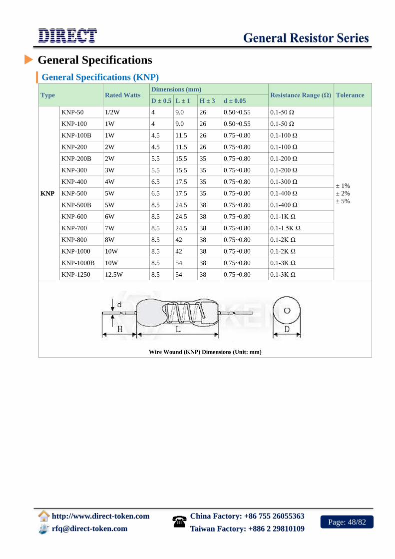
China Factory: +86 755 26055363
http://www.direct-token.com
[email protected] Taiwan Factory: +886 2 29810109 Page: 48/82
General Specifications
General Specifications (KNP)
Type Rated Watts Dimensions (mm)
Resistance Range (Ω) Tolerance D ± 0.5 L ± 1 H ± 3 d ± 0.05
KNP
KNP-50 1/2W 4 9.0 26 0.50~0.55 0.1-50 Ω
± 1%
± 2%
± 5%
KNP-100 1W 4 9.0 26 0.50~0.55 0.1-50 Ω
KNP-100B 1W 4.5 11.5 26 0.75~0.80 0.1-100 Ω
KNP-200 2W 4.5 11.5 26 0.75~0.80 0.1-100 Ω
KNP-200B 2W 5.5 15.5 35 0.75~0.80 0.1-200 Ω
KNP-300 3W 5.5 15.5 35 0.75~0.80 0.1-200 Ω
KNP-400 4W 6.5 17.5 35 0.75~0.80 0.1-300 Ω
KNP-500 5W 6.5 17.5 35 0.75~0.80 0.1-400 Ω
KNP-500B 5W 8.5 24.5 38 0.75~0.80 0.1-400 Ω
KNP-600 6W 8.5 24.5 38 0.75~0.80 0.1-1K Ω
KNP-700 7W 8.5 24.5 38 0.75~0.80 0.1-1.5K Ω
KNP-800 8W 8.5 42 38 0.75~0.80 0.1-2K Ω
KNP-1000 10W 8.5 42 38 0.75~0.80 0.1-2K Ω
KNP-1000B 10W 8.5 54 38 0.75~0.80 0.1-3K Ω
KNP-1250 12.5W 8.5 54 38 0.75~0.80 0.1-3K Ω
Wire Wound (KNP) Dimensions (Unit: mm)

China Factory: +86 755 26055363
http://www.direct-token.com
[email protected] Taiwan Factory: +886 2 29810109 Page: 49/82
Electrical Performance
Electrical Performance (KNP)
TEST ITEMS CONDITION SPEC
Operating Temperature Range -55℃ ~ 275℃(0W)
Resistance Temp. Coeff. Room temperature/100℃ up ± 300 PPM / ℃
Short Time Overload 10 times of rated wattage for 5 sec. ± 2 %
Rated Load Rated wattage 30 min. ± 1 %
Voltage Withstanding 500VAC 1 min ± 1 %
Temperature Cycling -20℃ ~ 85℃ 5 cycles ± 1 %
Load Life 70℃ on ~ off cycle 1000 hrs. ± 5 %
Moisture-Proof Load Life 40℃ 95% RH on ~ off cycle 500 hrs. ± 3 %
Incombustibility 16 times of rated wattage for 5 min not flamed
(KNP) Power derating curve

China Factory: +86 755 26055363
http://www.direct-token.com
[email protected] Taiwan Factory: +886 2 29810109 Page: 50/82
Application Notes
Application Notes of Wire wound Resistors (KNP) When being used in AC circuits, some wirewound structures give inductance ingredients or parasitic capacity,
so they may cause unusual phenomena such as oscillations etc. Quorum deviations of other components
should be carefully taken into account for use.
Application and Placement: Wire wound resistors use different gauges of wire as resistance elements.
Sometimes the gauge is extremely thin (finer than a strand of human hair) and very susceptible to breakage in
environments containing salts, ash, dust and corrosives. Avoid utilization in such environments.
Do not install in dusty areas because the accumulation will cause shorts and poor conductance.
Order Codes
Order Codes (KNP)
KNP-100 1W 10R J P
Part Number
KNP
Rated Power
(W)
Resistance Value (Ω)
0R1 0.1Ω
1R 1RΩ
10R 10RΩ
100R 100RΩ
1K 1KΩ
Resistance Tolerance
(%)
F ±1%
G ±2%
J ±5%
Package
P Bulk
TB Taping Box

China Factory: +86 755 26055363
http://www.direct-token.com
[email protected] Taiwan Factory: +886 2 29810109 Page: 51/82
Non-Inductive Wire wound Resistor
(KNPN)
Product Introduction
Features :
Low cost
Excellent pulse load capability
Non-inductive Ayrton Perry winding
A wide resistance range 0.1Ω to 50Ω
A wide range of power ratings 0.5W to 6W
Operating temperature range -55℃ ~ 155℃
Products with Pb-free Terminations and RoHS compliant
Applications :
Power tools
Current sensing
Consumer applications
Power supplies, Welders
High voltage applications
High-switching applications
Home entertainment, appliances
Direct Electronics has introduced a non-inductive version KNPN
resistor of conformal coated, leaded wire wounds. The KNPN
non-inductive wire wound resistor offers the expected performance
with the added characteristic of vastly improved inductance, making
it suitable for high-switching applications.
Wire wound technology has long been known as a leading
technology for power resistor needs though it is inherently inductive.
Known as Ayrton Perry winding, a non-inductively wound has one
winding in one direction and one in the other direction.
By using a non-inductively wound version this greatly reduces the inductance of any given resistor
size and value combination; however, it does not completely eliminate the inductance.
This non-inductive winding is available in all standard KNPN sizes from 0.5 watts up to 6 watts with
options 1%, 2% and 5% tolerance. The KNPN series is RoHS compliant and also can be supplied with
radial, goalpost or lancet preformed leads.
To address your need for technical and economic success in a timely manner, our custom solutions are
available. Contact us with your specific needs. Or link to Direct official website "General Purpose
Resistors" for more information.
Non-inductive Wire Wound Resistor Improves Inductance
for High Frequency Applications.

China Factory: +86 755 26055363
http://www.direct-token.com
[email protected] Taiwan Factory: +886 2 29810109 Page: 52/82
General Specifications
General Specifications (KNPN)
Type Rated
Watts
Dimensions (Unit: mm) Resistance
Range (Ω) Tolerance
D ± 0.5 L ± 1 H ± 3 d ± 0.05
KNPN
KNPN-50 1/2W 4 9.0 26 0.50~0.55 0.1-10 Ω
± 1%
± 2%
± 5%
KNPN-100 1W 4 9.0 26 0.50~0.55 0.1-10 Ω
KNPN-100B 1W 4.5 11.5 26 0.75~0.80 0.1-10 Ω
KNPN-200 2W 4.5 11.5 26 0.75~0.80 0.1-10 Ω
KNPN-200B 2W 5.5 15.5 35 0.75~0.80 0.1-20 Ω
KNPN-300 3W 5.5 15.5 35 0.75~0.80 0.1-20 Ω
KNPN-400 4W 6.5 17.5 35 0.75~0.80 0.1-30 Ω
KNPN-500 5W 6.5 17.5 35 0.75~0.80 0.1-30 Ω
KNPN-500B 5W 8.5 24.5 38 0.75~0.80 0.1-50 Ω
KNPN-600 6W 8.5 24.5 38 0.75~0.80 0.1-50 Ω
Non-inductive Resistor (KNPN) Dimensions

China Factory: +86 755 26055363
http://www.direct-token.com
[email protected] Taiwan Factory: +886 2 29810109 Page: 53/82
Electrical Performance
Electrical Performance (KNPN)
TEST ITEMS CONDITION SPEC
Operating Temperature Range -55℃ ~ 275℃ (0W)
Resistance Temp. Coeff. Room temperature/100℃ up ± 300 PPM /℃
Short Time Overload 10 times of rated wattage for 5 sec. ± 2 %
Rated Load Rated wattage 30 min. ± 1 %
Voltage Withstanding 500VAC 1 min ± 1 %
Temperature Cycling -20℃ ~ 85℃ 5 cycles ± 1 %
(KNPN) Power derating curve

China Factory: +86 755 26055363
http://www.direct-token.com
[email protected] Taiwan Factory: +886 2 29810109 Page: 54/82
Application Notes
Application Notes of Non-inductive Wire Wounds (KNPN) When being used in AC circuits, some wirewound structures give inductance ingredients or parasitic capacity,
so they may cause unusual phenomena such as oscillations etc.
Quorum deviations of other components should be carefully taken into account for use.
Application and Placement: Wire wound resistors use different gauges of wire as resistance elements.
Sometimes the gauge is extremely thin (finer than a strand of human hair) and very susceptible to breakage in
environments containing salts, ash, dust and corrosives. Avoid utilization in such environments.
Do not install in dusty areas because the accumulation will cause shorts and poor conductance.
Order Codes
Order Codes (KNPN)
KNPN-100 1W 10R J P
Part Number
KNPN
Rated Power
(W)
Resistance Value (Ω)
0R1 0.1Ω
1R 1Ω
1R2 1.2Ω
10R 10Ω
12R 12Ω
Resistance Tolerance
(%)
F ±1%
G ±2%
J ±5%
Package
P Bulk
TB Taping Box

China Factory: +86 755 26055363
http://www.direct-token.com
[email protected] Taiwan Factory: +886 2 29810109 Page: 55/82
Power Wire wound Resistor
(KNP-R)
Product Introduction
Features :
Excellent load life stability
High Precision and reliability
Axial ceramic-silicone coated
Meets the Standards of MIL-R-26E
RoHS compliant with 100% lead free
Applications :
Radar, Ground Vehicles
Communications systems
Bias supply, Current shunts, Voltage dropping
Motor speed controls, Voltage divider networks
Medical instrumentation and Medical implantables
Direct’s highest quality conformal axial terminal ceramic-silicone
coated KNP-R power resistors for applications requiring high
stability and precision. The KNP-R wire-wound has a low
temperature coefficient and maintain a high degree of stability
under demanding conditions.
The power precision KNP-R series meeting MIL-R-26E (U and V
characteristics) and surface temperature (hot spot) 375℃ max.
Resistors with a wide range of 0.01Ω ~ 82kΩ, covering applications
from precision to power. Products with lead-free terminations meet EU RoHS and China RoHS
requirements.
Operating temperature range is -55℃ ~ +375℃ and derated power at high ambient temperatures as
according to the chart below. Direct is equipped to design and produce custom components to meet
many design and reliability demands. In addition to standard military-grade resistor products, we also
have many resistive products designed to meet various source-controlled drawings.
Contact us with your specific needs. Or link to Direct official website "General Purpose Resistors" for
more information.
Characteristics U:
275℃ Maximum hot spot temperature. 1% Maximum ΔR in 1000 hours load life.
Characteristics V:
375℃ Maximum hot spot temperature. 3% Maximum ΔR in 1000 hours load life.
Power Wire Wound Resistors Boast Consistent Precision
Power Operation.

China Factory: +86 755 26055363
http://www.direct-token.com
[email protected] Taiwan Factory: +886 2 29810109 Page: 56/82
Technical Specifications
Technical Specifications (KNP-R)
Type MIL -
R-26E
Power Rating (W) Max. Working
Voltage (V) Resistance Range (Ω)
Dimensions
(Unit: mm)
U (275℃) V (375℃) U (275℃) V (375℃) 0.1%,
0.25%, 0.5%
1%, 2%,
3%, 5% L±0.81 D±0.81 d±0.1
KNP-R1/4 - 0.40 - 20 - 10~950 1~3.4K 6.35 1.98 0.51
KNP-R1/2 RW70 0.75 - 29 - 10~1.3K 1~4.9K 7.92 1.98 0.51
KNP-R1A - 1.00 - 53 - 1~2.7K 0.1~10.4K 10.31 2.36 0.64
KNP-R1 RW69 1.10 - 62 - 1~4.0K 0.1~15K 13.49 2.36 0.64
KNP-R2A - 2.50 3.25 138 157 1~8.6K 0.01~32.3K 12.70 5.33 0.81
KNP-R2 RW79 3.00 3.75 135 148 1~5K 0.01~2K 13.49 4.06 0.81
KNP-R3A - 3.00 3.75 135 148 1~6.5K 0.01~34.5K 14.27 5.33 0.81
KNP-R3 - 3.25 4.75 185 220 1~11.4K 0.01~42.1K 20.62 5.33 1.02
KNP-R4 RW67 4.00 5.50 210 250 1~12.7K 0.01~47.1K 15.88 7.62 1.02
KNP-R5 RW74 5.00 6.50 330 376 0.5~24.5K 0.01~51K 22.22 7.62 1.02
KNP-R7 RW68 7.00 9.00 504 576 0.5~41.4K 0.01~75K 30.94 9.52 1.02
KNP-R10 RW78 10.00 13.00 799 911 0.5~71.3K 0.01~82K 45.21 9.52 1.02
KNP-R Power Derating Curve
Power Precision Wire wound Resistor (KNP-R) Dimensions
Temperature Coefficient: 1 Ω and below ± 150 ppm/℃, 1 Ω to 9.9 Ω ± 100 ppm/℃, 10 Ω and above ± 100 ppm/℃, (50 ppm/℃
on request)

China Factory: +86 755 26055363
http://www.direct-token.com
[email protected] Taiwan Factory: +886 2 29810109 Page: 57/82
Electrical Performance
Electrical Performance (KNP-P)
Test Items Test Method Specifications
Short Time Overload 2.5 times of rated voltage 5 sec. ΔR±(2%+0.05Ω)
Rated Load Rated wattage 30 minutes. ΔR±(1%+0.05Ω)
Voltage Withstanding 500VAC 1 minute. ΔR±(1%+0.05Ω)
Insulation Resistance 500V 20MΩ
Temp. Cycle -20℃ ~ 85℃ 5 cycles ΔR±(1%+0.05Ω)
Soldering After Resistance 235℃ for 3 sec ΔR±(0.5%+0.05Ω)
Incombustibility 16 times of rated wattage for 5 min. Not flamed
Load Life +25℃, 1.5Hrs on ~ 0.5Hrs off cycle, 1000 Hrs. U: ΔR±(1%+0.05Ω)
V: ΔR±(3%+0.05Ω)
Application Notes
Application Notes of Wire wounds (KNP-R) When being used in AC circuits, some wirewound structures give inductance ingredients or parasitic
capacity, so they may cause unusual phenomena such as oscillations etc. Quorum deviations of other
components should be carefully taken into account for use.
Application and Placement: Wirewound resistors use different gauges of wire as resistance elements.
Sometimes the gauge is extremely thin (finer than a strand of human hair) and very susceptible to breakage
in environments containing salts, ash, dust and corrosives. Avoid utilization in such environments.
Do not install in dusty areas because the accumulation will cause shorts and poor conductance.
Order Codes
Order Codes (KNP-R)
KNP-R3A U 100R B P
Part Number
KNP-R
Characteristic
(℃)
U 275℃
V 375℃
Resistance Value
(Ω)
0R1 1.0Ω
1R 1Ω
100R 100Ω
1K 1000Ω
Resistance
Tolerance (%)
B ±0.1%
C ±0.25%
D ±0.5%
F ±1%
G ±2%
H ±3%
J ±5%
Package
P Bulk
TB Taping Box

China Factory: +86 755 26055363
http://www.direct-token.com
[email protected] Taiwan Factory: +886 2 29810109 Page: 58/82
High Precision Wire wound Resistor
(BWW)
Product Introduction
Features :
Axial Moulded
Excellent load life stability
Insulation, Moisture Proof
High Precision and reliability
Meets the Standards of MIL-R-93
RoHS compliant with 100% lead free
Applications :
Electrical loads, Filament dropping
DC/DC converters, AC/DC inverters
High-voltage bleeders, Dynamic braking
Capacitor charging/discharging regulation
Motor speed controls, Voltage divider networks
Bias supply, Current shunts, Voltage dropping,
Crow-bar circuits
The new BWW series moulded axial leaded wire wound resistors
from Direct use high-purity alumina ceramic cores with wire
winding which spot are welded by precision CNC machine tools
to ensure total operational consistency throughout.
Also, using advanced encapsulation die/mould technologies,
these precision power resistors are encapsulated with epoxy
molding compound.
The BWW models possess a wide resistance value from 0.1Ω to
39KΩ and meet the stringent requirements of MIL-R-93. Ayrton
Perry non-inductive windings are available on request. The BWW precision version has low Ohmic
values for current sensing applications.
All versions are miniaturized for better power to dimension ratios and are available in 0.5W to 10W
rated power at 25℃. Tolerance is available in ±0.1%, ±0.25%, ±0.5%, ±1% and ±2% with TCR
±25PPM/℃, ±50PPM/℃ and ±150PPM/℃ which makes them ideally suited for use in precision
applications.
The BWW series is RoHS compliant with 100% Sn (lead free) coated terminals. To address your need
for technical and economic success in a timely manner, our custom solutions are the best option.
Contact us with your specific needs. Or link to Direct official website "General Purpose Resistors" for
more information.
(BWW) Precision Power Resistors Operate in Harsh
Environments.
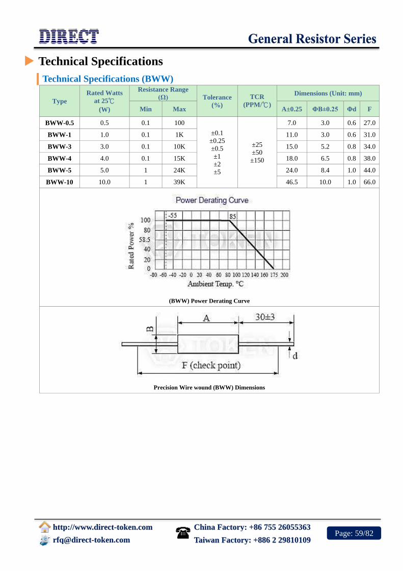
China Factory: +86 755 26055363
http://www.direct-token.com
[email protected] Taiwan Factory: +886 2 29810109 Page: 59/82
Technical Specifications
Technical Specifications (BWW)
Type
Rated Watts
at 25℃
(W)
Resistance Range
(Ω) Tolerance
(%)
TCR
(PPM/℃)
Dimensions (Unit: mm)
Min Max A±0.25 ΦB±0.25 Φd F
BWW-0.5 0.5 0.1 100
±0.1
±0.25
±0.5
±1
±2
±5
±25
±50
±150
7.0 3.0 0.6 27.0
BWW-1 1.0 0.1 1K 11.0 3.0 0.6 31.0
BWW-3 3.0 0.1 10K 15.0 5.2 0.8 34.0
BWW-4 4.0 0.1 15K 18.0 6.5 0.8 38.0
BWW-5 5.0 1 24K 24.0 8.4 1.0 44.0
BWW-10 10.0 1 39K 46.5 10.0 1.0 66.0
(BWW) Power Derating Curve
Precision Wire wound (BWW) Dimensions

China Factory: +86 755 26055363
http://www.direct-token.com
[email protected] Taiwan Factory: +886 2 29810109 Page: 60/82
Electrical Performance
Electrical Performance (BWW)
Test Items Test Conditions Specifications
Operating Temp. Range -55℃ ~ 175℃
Insulation Resistance 500V >1GΩ
Dielectric Withstanding Voltage 500V AC 1 Min. ΔR ≤ ±0.1%R
Load Life 70℃ on~off cycle 1000 Hrs. ΔR ≤ ±1%R
Moisture-Proof Load Life 40℃ 95% RH on~off cycle 21 Hrs. ΔR ≤ ±0.2%R
Resistance to soldering heat 350℃, 3.5s ΔR ≤ ±0.1%R
Solderability 235±5℃, 5s(solder bath method) IEC68-2-20(1968)
Application Notes
Application Notes of Wire wounds (BWW) When being used in AC circuits, some wirewound structures give inductance ingredients or parasitic
capacity, so they may cause unusual phenomena such as oscillations etc. Quorum deviations of other
components should be carefully taken into account for use.
Application and Placement: Wire wound resistors use different gauges of wire as resistance elements.
Sometimes the gauge is extremely thin (finer than a strand of human hair) and very susceptible to breakage
in environments containing salts, ash, dust and corrosives. Avoid utilization in such environments.
Do not install in dusty areas because the accumulation will cause shorts and poor conductance.
Order Codes
Order Codes (BWW)
BWW - 1W 100R F D P
Part
Number
BWW
Rated Power
(W)
Resistance Value
(Ω)
0R1 0.1Ω
100R 100Ω
1K 1000Ω
Resistance
Tolerance (%)
B ±0.1%
C ±0.25%
D ±0.5%
F ±1%
G ±2%
TCR (PPM/℃)
C ±25PPM/℃
D ±50PPM/℃
K ±150PPM/℃
Package
P Bulk

China Factory: +86 755 26055363
http://www.direct-token.com
[email protected] Taiwan Factory: +886 2 29810109 Page: 61/82
Zero Ohm & Jumper Wire Resistors
(ZO, JW)
Product Introduction
Features :
Maximum resistance 0.05Ω
RoHS compliant with 100% lead free
Lead Material: Tin-plated copper lead
Ideal straight - through between point on PC
Boards
Packing: Tape/Reeled or Bulk
Applications :
Interrupt processing
Input and output distribution
Ideal connection for circuit boards
Dummy components on a PCB test board
Jumper Wire (JW series a zero-ohm link) and zero-ohm resistor
(ZO series) are a link used to connect traces on a printed circuit
board that is packaged in the same format as a resistor.
The resistance of JW and ZO series is only approximately zero;
only a maximum 0.05Ω is specified. Thus, a fractional tolerance
(as a percentage of the zero-ohm ideal value) would be infinite
and is not specified.
Axial through-hole zero-ohm resistors are especially suited for
automatic machine insertion and generally marked with a single black band.
Direct's JW and ZO Series offer a quick solution to the following problems:
1. Circuit tuning by changing point connections.
2. An "after the fact design" the requires new point connections.
3. Inability to connect two points on a PCB board due to other circuit paths which must be
crossed over.
Allowing customers to standardize on the PCB layout and use jumper wire and zero ohm resistor for
required model variations, Direct has developed a wider version for the interconnection device
between points on a PCB board as jumper wires or crossovers. Contact us with your specific needs.
For more information, please link to Direct official website "General Purpose Resistors".
A Quick Solution to PCB Board Connections.

China Factory: +86 755 26055363
http://www.direct-token.com
[email protected] Taiwan Factory: +886 2 29810109 Page: 62/82
ZO General Specification
General Specification (Unit: mm) Zero Ohm Resistor (ZO)
Type Rating Dimension (mm)
L Max. D Max. H ± 3 d+0.02-0.04
ZO - 1/8 0.125W 4.2 2.0 28 0.5
ZO- 1/4 0.25W 6.8 2.5 28 0.5
Zero Ohm Resistors (ZO) Dimensions
JW General Specification
General Specification (Unit: mm) Jumper Wire (JW)
Type L±1 d+0.02 -0.04 H P
JW-A 61.5 0.5 3 - 10 5 - 30
JW-B 61.5 0.6 3 - 10 5 - 30
Jumper Wire (JW) Dimensions

China Factory: +86 755 26055363
http://www.direct-token.com
[email protected] Taiwan Factory: +886 2 29810109 Page: 63/82
Electrical Performance
Electrical Performance (ZO, JW)
Requirements Characteristics
Maximum Resistance 0.05Ω
Lead Material tin-plead copper
Body Material Electrical grade, high performance molding compound
Dielectric Withstanding Voltage Atomspheric-500V RMS, Reduced-325V RMS
Insulation Flammability Resistor Insulation is self-extinguishing within 10
seconds after externally applied flame is removed.
Current Rating 25 AMPS at 25℃, dreading to 0 AMPS at 150℃
Order Codes
Order Codes (ZO, JW)
ZO-1/4 0.25W TB
Part Number
ZO-1/4
ZO-1/8
JW-A
JW-B
Rated Power (W)
0.25W
0.125W
Package
P Bulk
TB Taping Box

China Factory: +86 755 26055363
http://www.direct-token.com
[email protected] Taiwan Factory: +886 2 29810109 Page: 64/82
Wirewound Resistor (KNP-VE/LF)
Product Introduction
Features :
Excellent pulse load capability, Axial leads, All-welded construction
Power ratings 1W to 30W, Resistance range 0.1Ω to 47KΩ, Tolerance ±2%, ±5%
Products with Pb-free Terminations and RoHS compliant, rugged vitreous enamel coating withstands high
humidity and temperature cycling
Applications :
Consumer applications, Power supplies, Welders, High voltage applications
Power tools, High-switching applications, Home entertainment, appliances
The KNP-VE/LF Series of vitreous enamel coated power
resistors from Direct offers a cost-competitive alternative over
the 1W-30W power range. The range is available with resistance
values of 0.1Ω to 47KΩ in working voltage of 75V to 1000V,
and with body sizes that match the industry standards.
Vitreous enamelled resistors were introduced at a time when
alternative directly applied coatings could not withstand the
thermal stresses caused by the resistors' high body temperatures.
Direct offers the durability of a lead free conformal vitreous
enamel coating, permits the KNP-VE/LF Series resistors to maintain a hard coating while operating at
high temperatures. Mechanical integrity is enhanced by the all-welded construction.
Power KNP-VE/LF Wirewound Series are ideal for computer, communications and industrial
applications in which cost, quality, and reliability are key considerations. The KNP-VE/LF series is
RoHS compliant and Ayrton Perry noninductive windings are available on request.
To address your need for technical and economic success in a timely manner, our custom solutions are
the best choice. Contact us with your specific needs. Or link to Direct official website "General
Purpose Resistors" for more information.
RoHS Vitreous Enamel Coated Wirewound Resistors
(KNP-VE/LF) Boost High Energy.
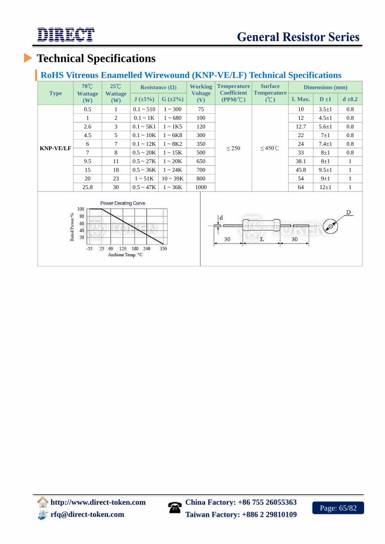
China Factory: +86 755 26055363
http://www.direct-token.com
[email protected] Taiwan Factory: +886 2 29810109 Page: 65/82
Technical Specifications
RoHS Vitreous Enamelled Wirewound (KNP-VE/LF) Technical Specifications
Type
70℃
Wattage
(W)
25℃
Wattage
(W)
Resistance (Ω) Working
Voltage
(V)
Temperature
Coefficient
(PPM/℃)
Surface
Temperature
(℃)
Dimensions (mm)
J (±5%) G (±2%) L Max. D ±1 d ±0.2
KNP-VE/LF
0.5 1 0.1 ~ 510 1 ~ 300 75
≤ 250 ≤ 450℃
10 3.5±1 0.8
1 2 0.1 ~ 1K 1 ~ 680 100 12 4.5±1 0.8
2.6 3 0.1 ~ 5K1 1 ~ 1K5 120 12.7 5.6±1 0.8
4.5 5 0.1 ~ 10K 1 ~ 6K8 300 22 7±1 0.8
6 7 0.1 ~ 12K 1 ~ 8K2 350 24 7.4±1 0.8
7 8 0.5 ~ 20K 1 ~ 15K 500 33 8±1 0.8
9.5 11 0.5 ~ 27K 1 ~ 20K 650 38.1 8±1 1
15 18 0.5 ~ 36K 1 ~ 24K 700 45.8 9.5±1 1
20 23 1 ~ 51K 10 ~ 39K 800 54 9±1 1
25.8 30 0.5 ~ 47K 1 ~ 36K 1000 64 12±1 1

China Factory: +86 755 26055363
http://www.direct-token.com
[email protected] Taiwan Factory: +886 2 29810109 Page: 66/82
Electrical Performance
Vitreous Enamelled Wirewound (KNP-VE/LF) Performance
Test Item Characteristics Test Methods
SJ1330-78
Solderability Free flow of solder 235±5℃, 2s Groove welding
Terminal strength ΔR ≤ ± (1%R+0.05Ω) ≤4.3W 10N, ≥6W 20N
Overloading ΔR ≤ ± (1%R+0.05Ω) θ A=-55℃ θ B=+200℃, 5 Cycles
Temperature Change ΔR ≤ ± (1%R+0.05Ω) 235±5℃, 2s Groove welding
Collision Test ΔR ≤ ± (1%R+0.05Ω) Acceleration 390m/s2, 4000 times
Impact Test ΔR ≤ ± (1%R+0.05Ω) Acceleration 490m/s2, 11ms, 18 times
Vibration Test ΔR ≤ ± (1%R+0.05Ω) Frequency 10-500Hz, Acceleration
98m/s2, 6h
Temperature Rise ≤245℃ Apply rated power Load
Constant Damp Heat ΔR ≤ ± (5%R+0.05Ω) Temperature 40±2℃, Temperature
93+2/-3%, 56h
Room temperature Durability ΔR ≤ ± (5%R+0.05Ω) Rated power load at room temperature
1000h
Order Codes
RoHs Vitreous Enamelled Resistors - (KNP-VE/LF) Order Code
KNP-VE - 11W 10R J P
Type
KNP-VE Vitreous
Enamelled
KNP-LF
RoHs
Vitreous
Enamelled
Rated Power (W) @25℃
2W 2W
5W 5W
11W 11W
30W 30W
Resistance (Ω)
1R 1Ω
110R 110Ω
1K1 1.1KΩ
10K 10KΩ
Resistance
Tolerance
G ±2%
J ±5%
Package
TB Taping
Box
P Bulk

China Factory: +86 755 26055363
http://www.direct-token.com
[email protected] Taiwan Factory: +886 2 29810109 Page: 67/82
Power Wirewound Vitreous
Enameled Resistors (DRB20)
Product Introduction
Features :
Small size, high power.
Glaze coating, simple structure, easy to install.
Fixed resistance and adjustable resistance optional.
Applications :
Electric tools, Consumer product
applications.
Power supply, high voltage applications.
Welding machine, switch applications.
Power Wirewound Enameled Resistor (DRB20) Is a cylindrical
ceramic tube at both ends clips to fixed terminals. Ceramic tube
winding copper nickel or nickel-chromium alloy resistance wire.
Surface coated with moisture-resistant, heat-resistant, non-corrosive,
non-flammable coatings (such as silicone, epoxy, cement, glazed
porcelain, etc.). After high temperature treatment, the resistor dried
and insulation fixed, then fitted with fixed foot frame.
Due to good flexibility, (DRB20) can be made of multi-terminal, low
inductive resistance, semi-adjustable type of various types of resistors.
Resistance range from 1.7Ω to 75KΩ, with power ranges from 8W to 500W, and optional tolerance accuracy
of ±1%、±5%、±10%. Size of cylindrical ceramic tube matches with industry standards .
Tubular series power-glaze wire wound resistor (DRB20) widely used as brake resistors, bleeder resistors, aging
resistors, brake resistors. According to different occasions, but also can be called brake resistors, discharge
resistors, load resistors, current limiting resistors, charging resistors or discharge resistors. Non-inductance
series adopts Ayrton Perry winding method to eliminate inductance parasitic effect, so as to minimize
inductance, suitable for high energy consumption, high-temperature environment.
Be glazed coating protection, not afraid of external mechanical strength and dust environment. Not only large
power and strong, shock-resistant, but also features good heat dissipation. This (DRB20) is easy to install and
use. This is suitable for a variety of applications. More than 1.2 times the same specifications or requirements of
peer production, more power, can be long time loading and impact. Applications include industrial machinery,
load testing, power distribution, instrumentation and automation control devices.
Direct Electronics (DRB20) vitreous enameled power wirewound resistors meet RoHS compliant, lead-free
standard and short production cycle. Those Products widely used in power tools, switch applications, power
supplies, welding machines, high voltage applications, consumer product applications, home entertainment,
home appliances products. For the customized special applications, please contact our sales to discuss the details.
Or link to Direct official website "General Purpose Resistors" for more information.
Token (DRB20) Vitreous Enameled Resistors - strong
moisture-proof characteristics, high energy power.

China Factory: +86 755 26055363
http://www.direct-token.com
[email protected] Taiwan Factory: +886 2 29810109 Page: 68/82
Technical Specifications
Power Wirewound Glaze Resistors (DRB20) Dimensions (Unit: mm)
Type Dimensions (mm)
L D d H h L1 K b t d1
DRB20(T*)-8 35±1.5 14±2 5.5±0.5
28.5±2.5
3.5±0.8 4.5±1 2±0.8
DRB20(T)-10 41±1.5 14±2 5.5±0.5 31±3 28.5±2.5 20±2 6±2 3.5±0.8 4.5±1 2±0.8
DRB20(T)-16 45±1.5 17±2 8±0.5 34±3 31±2.5 23±2 6±2 3.5±0.8 4.5±1 2±0.8
DRB20(T)-20 51±2 17±2 8±0.5 34±3 31±2.5 30±3 6±2 3.5±0.8 4.5±1 2±0.8
DRB20(T)-25 51±2 21±2.5 12±0.6 39±3 35±2.5 30±3 6±2 3.5±0.8 4.5±1 2±0.8
DRB20(T)-30 71±2.2 21±2.5 12±0.6 39±3 35±2.5 44±3 6±2 3.5±0.8 4.5±1 2±0.8
DRB20(T)-40 87±2.2 21±2.5 12±0.6 39±3 35±2.5 57±3
3.5±0.8 4.5±1 2±0.8
DRB20(T)-50 91±2.4 29±3 20±1.1 47±3 43±2.5 60±3 7±2 4.5±1 6±1 2.5±0.8
DRB20(T)-75 140±3.2 29±3 20±1.1 47±3 43±2.5 110±3 7±2 4.5±1 6±1 2.5±0.8
DRB20(T)-100 170±3.5 29±3 20±1.1 47±3 43±2.5 140±3 7±2 4.5±1 6±1 2.5±0.8
DRB20(T)-150 215±4 29±3 20±1.1 47±3 43±2.5 185±3 7±2 4.5±1 6±1 4±0.8
DRB20(T)-200 215±4 38±3 38±3 61±3 58±2 160±3 7±2 8±1 9±1 4±0.8
DRB20(T)-250 266±4 30±2 30±2 50±3 50±2 210±4 7±2 8±1 9±1 4±0.8
DRB20(T)-300 266±4 36±2 36±2 58±3 58±2 210±4 8±2 8±1 9±1 4±0.8
DRB20(T)-400 250±4 54±2 54±2 76±3 77±3 180±4 10±2 8±1 16±1 8±1
DRB20(T)-500 300±4 54±2 30±2 76±3 77±3 230±4 10±2 8±1 16±1 8±1
Power Wirewound Glaze Resistors (DRB20) Dimensions (Unit: mm)
Power Wirewound Glaze Adjustable Resistors (DRB20-T) Dimensions (Unit: mm)
T* : Adjustable Wirewound Resistors。

China Factory: +86 755 26055363
http://www.direct-token.com
[email protected] Taiwan Factory: +886 2 29810109 Page: 69/82
Specification
Power Wirewound Vitreous Enameled Resistors (DRB20) Specification
Type Rating Power (W) Resistance (Ω) Weight (g)
DRB20 DRB20-T Fixed Adjustable
DRB20
(DRB20T)
8 5.1-3.3K
23
10 5.1-10K 5.1-200 17 34
16 5.1-15K 5.1-220 36 42
20 5.1-20K 5.1-430 44 52
25 10-24 10-510 57 68
30 10-30K 10-1K 80 90
40 20-51K 20-1.2K 98 110
50 24-56K 20-1.5K 132 150
75 20-51K 24-2K 253 270
100 24-62K 20-4.3K 286 200
150 20-75K 20-4.3K 385 300
200 4.7-68K 5.1-4.3K 475 400
250 4.7-68K 5.1-4.3K 510 530
300 1.7-68K 5.1-4.3K 630 650
400 4.7-75K 6.2-5.1K 1000 1050
500 4.7-75K 6.2-5.1K 1340 1400
Electrical Performance
Power Wirewound Enameled Resistor (DRB20) Performance
Test Item Characteristics Test Methods
Solderability Even sticky tin HiSnPb39, 75W Soldering iron method,
tinning
Insulation resistance >20MΩ/cm2 500V DC test voltage
Insulation voltage No breakdown, arcing 2000V DC or 50Hz AC peak with the
same
Body strength ΔR ≤ ± (1%R + 0.05Ω) ≤40W Loading 30N, ≥50W Loading
100N
Vibration ΔR ≤ ± (1%R + 0.05Ω) Frequency 10-500Hz, Acceleration
98m/s2, 1h
Collision test ΔR ≤ ± (1%R + 0.05Ω) Frequency 40-80 次/min, Acceleration
245m/s2, 2000 times
Temperature Rise <325°C Apply rated power Load
Rapid temperature changes ΔR ≤ ± (2%R + 0.1Ω) θ A=-55°C θ B=+200°C, 5 Cycles
Constant Damp Heat ΔR ≤ ± (2%R + 0.1Ω) Temperature 40±2°C, Temperature
93±2%RH, 96h
Over loading ΔR ≤ ± (2%R + 0.1Ω) Apply 10 times the rated power load 5s
Room temperature durability ΔR ≤ ± (5%R + 0.1Ω) Apply rated power load 1000h

China Factory: +86 755 26055363
http://www.direct-token.com
[email protected] Taiwan Factory: +886 2 29810109 Page: 70/82
Application Notes
Adjustable Wirewound Application Notes
Determination of End Resistance Value of (DRB20-T):
1. Resistance Range means you can choose one maximum resistance value (Max. Pickable Resistance / End resistance
value) at one of DRB20-T, FVR, DQS, DSRA, DSRB, BSR, BSQ, VR (Variable Resistor) type.
2. After End Resistance Value confirmed, the minimum resistance (start resistance value) will be determined by depending
on resistance of wire and wirewound type.
Power Rating of Variable Resistor:
The part Nunber formation of DRB20-T:
Product type - Rated Wattage - Max. Pickable Resistance (Ω) - Resistance Tolerance
Product type means one of FVR, DQS, DSRA, DSRB, BSR, BSQ, DRB20-T.
Rated Wattage means power rating at End Resistance Value.
Resistance Value (Ω) means maximum resistance value (End Resistance Value).
Resistance Tolerance means precision range of End Resistance Value.
1. Power Rating of VR (Variable Resistor) is determined by the maximum resistance value (End Resistance Value).
2. Resistance and Power Rating should be decreased while you are adjusting the screw.
Notes:
1. Adjustability is 10% to 90% of full resistance value.
2. Wattage is proportional to this adjusted resistance value.
Power Rating:
1. Based on 25°C free air rating. The stated wattage rating applies only when the entire resistance is in the circuit.
2. Setting the lug at an intermediate point reduces the wattage rating by approximately the same proportion.
3. Example: If the lug is set at half resistance, the wattage is reduced by approximately one-half.
If you need current constant type or special specifications, please feel free to contact us.

China Factory: +86 755 26055363
http://www.direct-token.com
[email protected] Taiwan Factory: +886 2 29810109 Page: 71/82
Order Codes
Power Wirewound Vitreous Glaze Resistors - (DRB20) Order Codes
DRB20 - T 8W 100R J
Type
DRB20
Adjustable
Resistance
Fixed
Resistance
T Adjustable
Resistance
Rating Power
(W)
8W 8W
20W 20W
100W 100W
500W 500W
Resistance Value
(Ω)
10R 10Ω
110R 110Ω
1K1 1.1KΩ
10K 10KΩ
Resistance
Tolerance
F ±1%
J ±5%
K ±10%
Inductance
Inductance
N Non-Inductance
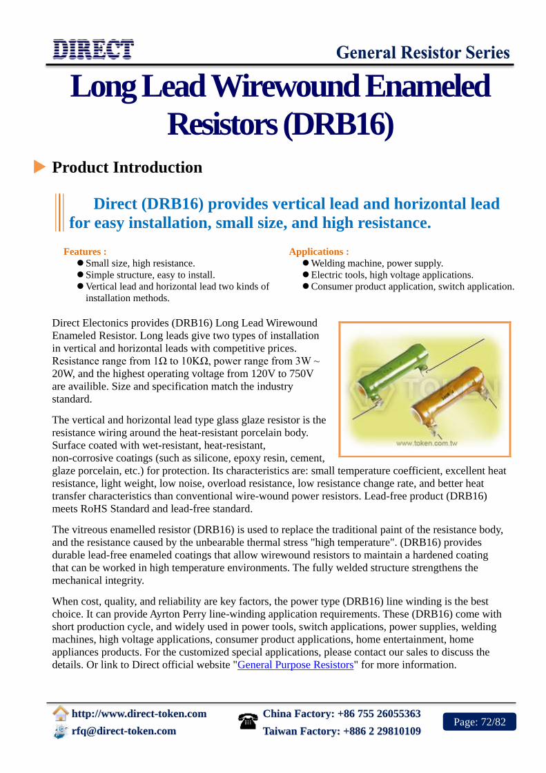
China Factory: +86 755 26055363
http://www.direct-token.com
[email protected] Taiwan Factory: +886 2 29810109 Page: 72/82
Long Lead Wirewound Enameled
Resistors (DRB16)
Product Introduction
Features :
Small size, high resistance.
Simple structure, easy to install.
Vertical lead and horizontal lead two kinds of
installation methods.
Applications :
Welding machine, power supply.
Electric tools, high voltage applications.
Consumer product application, switch application.
Direct Electonics provides (DRB16) Long Lead Wirewound
Enameled Resistor. Long leads give two types of installation
in vertical and horizontal leads with competitive prices.
Resistance range from 1Ω to 10KΩ, power range from 3W ~
20W, and the highest operating voltage from 120V to 750V
are availible. Size and specification match the industry
standard.
The vertical and horizontal lead type glass glaze resistor is the
resistance wiring around the heat-resistant porcelain body.
Surface coated with wet-resistant, heat-resistant,
non-corrosive coatings (such as silicone, epoxy resin, cement,
glaze porcelain, etc.) for protection. Its characteristics are: small temperature coefficient, excellent heat
resistance, light weight, low noise, overload resistance, low resistance change rate, and better heat
transfer characteristics than conventional wire-wound power resistors. Lead-free product (DRB16)
meets RoHS Standard and lead-free standard.
The vitreous enamelled resistor (DRB16) is used to replace the traditional paint of the resistance body,
and the resistance caused by the unbearable thermal stress "high temperature". (DRB16) provides
durable lead-free enameled coatings that allow wirewound resistors to maintain a hardened coating
that can be worked in high temperature environments. The fully welded structure strengthens the
mechanical integrity.
When cost, quality, and reliability are key factors, the power type (DRB16) line winding is the best
choice. It can provide Ayrton Perry line-winding application requirements. These (DRB16) come with
short production cycle, and widely used in power tools, switch applications, power supplies, welding
machines, high voltage applications, consumer product applications, home entertainment, home
appliances products. For the customized special applications, please contact our sales to discuss the
details. Or link to Direct official website "General Purpose Resistors" for more information.
Direct (DRB16) provides vertical lead and horizontal lead
for easy installation, small size, and high resistance.

China Factory: +86 755 26055363
http://www.direct-token.com
[email protected] Taiwan Factory: +886 2 29810109 Page: 73/82
Technical Specifications
Enameled Wirewound Resistor Long Leads (DRB16) - Specifications (Unit: mm)
Type
Rating
Power
(W)
Resistance
(Ω)
Resistance
Tolerance
(%)
Temperature
Coefficient
(ppm/°C)
Working
Voltage
(V)
Dimensions (mm)
L ±1 OD ±1 ID ±1 e ±3 d ±0.2 H ±1
DRB16-3 3W 1 ~ -1k
±5% (J)
±10% (K)
250
120 11 7.5 3.6 38±3 0.8 7
DRB16-5 5W 5 ~ -1.5k 150 16 8.5 3.6 38±3 0.8 11
DRB16-6 6W 6 ~ -4.7k 250 25 10.5 4.8 38±3 1 19
DRB16-12 12W 12 ~ -4.7k 600 44.5 10.5 4.8 38±3 1 36.5
DRB16-20 20W 20 ~ -10k 750 51 14.3 7.9 38±3 1 43
Horizontal Long Lead Enameled Wirewound Resistor (DRB16)
Vertical Long Lead Enameled Wirewound Resistor (DRB16)

China Factory: +86 755 26055363
http://www.direct-token.com
[email protected] Taiwan Factory: +886 2 29810109 Page: 74/82
Electrical Performance
Vitreous Enamelled Resistor (DRB16) Performance
Test Item Characteristics Test Methods
Solderability Free flow of solder 235°C ± 5°C, 2s Groove welding
Terminal strength ΔR ≤ ± (1%R + 0.05Ω) ≤4.3W 10N, ≥6W 20N
Overloading ΔR ≤ ± (1%R + 0.05Ω) Applied 10 times the rated power load
5s
Rapid temperature Change ΔR ≤ ± (1%R + 0.05Ω) θ A=-55°C θ B=+200°C, 5 Cycles
Collision Test ΔR ≤ ± (1%R + 0.05Ω) Acceleration 390m/s2, 4000 times
Impact Test ΔR ≤ ± (1%R + 0.05Ω) Acceleration 490m/s2, 11ms, 18 times
Vibration Test ΔR ≤ ± (2%R + 0.1Ω) Frequency 10-500Hz, Acceleration
98m/s2, 6h
Temperature Rise <245°C Apply rated power Load
Constant Damp Heat ΔR ≤ ± (5%R + 0.1Ω) Temperature 40±2°C, Temperature
93+2/-3%, 56h
Room temperature Durability ΔR ≤ ± (5%R + 0.1Ω) Rated power load at room temperature
1000h
Derating Curve
Derating Curve (DRB16)

China Factory: +86 755 26055363
http://www.direct-token.com
[email protected] Taiwan Factory: +886 2 29810109 Page: 75/82
Order Codes
Long Lead Enameled Wirewound Resistor - (DRB16) Order Codes
DRB16 - 3 10R J VL VE
Type
DRB16
Rating Power (W)
3 3W
5 5W
6 6W
12 12W
20 20W
Resistance
Value (Ω)
10R 10Ω
110R 110Ω
1K1 1.1KΩ
10K 10KΩ
Resistance
Tolerance
G ±2%
J ±5%
Lead Type
VL Vertical
Lead
HL Horizontal
Lead
Coating
VE Vitreous
Enamelled
LF RoHS
Enamelled
NF Nonflammable
Epoxy

China Factory: +86 755 26055363
http://www.direct-token.com
[email protected] Taiwan Factory: +886 2 29810109 Page: 76/82
Power Metal Film Flame-Proof
Resistors (FMF)
Product Introduction
Features :
High power in small packages, Low electrical noise.
Outstanding stability under a wide range of electrical and environmental stresses.
Pure tin plating provides compatibility with lead (Pb)-free and lead containing soldering processes.
Compatible with “Restriction of the use of Hazardous Substances” (RoHS) directive 2011/65/EU.
Applications :
Ballasts, Amplifiers, Power Supplies, Telecommunications
Household Appliances, Automotive, Computer, Precision Controls
Test Equipment and Instrumentation, Medical Equipment, Security Monitoring
Direct Electronics is a global engineering electronics supplier for
performance-critical applications, introducing the (FMF) series of Power Metal
Film Flame-Proof Resistors. Offering a combination of high precision and
handling high power conditions, this resistor is ideal for measuring power line
voltage for power condition and energy metering monitoring.
Direct (FMF) Flame-Proof Resistor is desogned to provide an alternative options
between Power Metal Oxide Resistors (RSS, RSN) and Precision Metal-Film
Resistors (MF). The (FMF) takes the power handling with flame-proof advantage
of metal oxide resistors and inherits the precision tolerance of (MF) metal film
resistors to provide a solution for customers looking for an industrial grade
flame-proof resistors.
The power of Flame-Proof Resistor (FMF) is rated at 1/4, 1/2WS, 1/2W, 1W, 2WS, 2W, 3WS, 3W, 5WS, 5W, and 7WS
respectively. Standard values from 0.1Ω to 10MΩ are available, E24, E-96, and E-192 nominal standard series provides
adequate "‘close value match" choice for designers. Maximum overload voltage specifies up to 1000V at 5W normal size
or 7WS minimum size.
The (FMF) resistors have excellent high power characteristics to improve reliability and reduce faults. With precision levels
of ±0.1% resistance tolerance and ±15ppm/°C TCR they free up designers’ error budgets, enabling savings elsewhere in the
circuit. Accuracy is ± 0.1%, ± 0.25%, ± 0.5%, ± 1%, ± 2%, and ± 5% precision tolerance, which saves the designer's error
budget and free up other parts of the circuit.
Structurally the resistors include a homogeneous sputtered metal alloy film on a high-aluminum ceramic rod and protect
with flame-proof coating. The resistance value in the film was adjusted to the final value by laser spiral cutting. The
terminals on both ends of the resistor are covered with a pure tin coating to avoid aging the contacts and a low melting
point solder can be used thereon. Contact us with your specific needs. For more information, please link to Direct official
website "General Purpose Resistors".
Flame Proof Resistor (FMF), low TCR, low noise and high
precision for telecommunication, comsumer products.
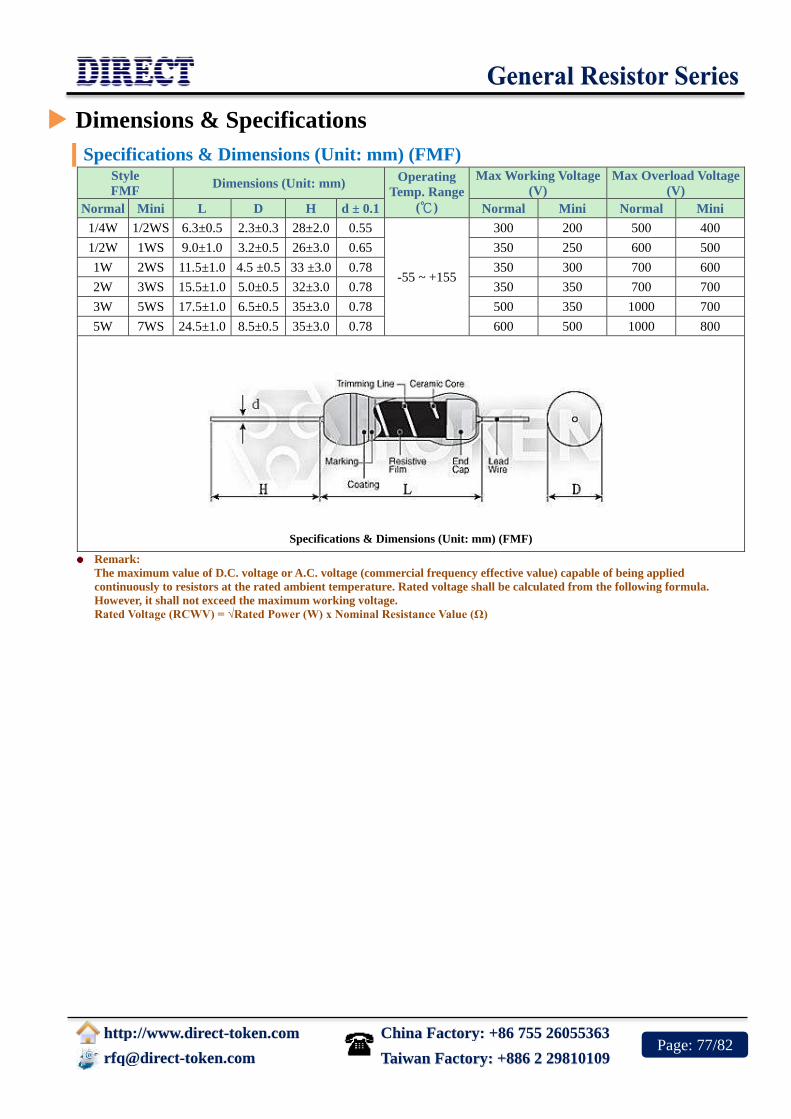
China Factory: +86 755 26055363
http://www.direct-token.com
[email protected] Taiwan Factory: +886 2 29810109 Page: 77/82
Dimensions & Specifications
Specifications & Dimensions (Unit: mm) (FMF) Style
FMF Dimensions (Unit: mm)
Operating
Temp. Range
(℃)
Max Working Voltage
(V)
Max Overload Voltage
(V)
Normal Mini L D H d ± 0.1 Normal Mini Normal Mini
1/4W 1/2WS 6.3±0.5 2.3±0.3 28±2.0 0.55
-55 ~ +155
300 200 500 400
1/2W 1WS 9.0±1.0 3.2±0.5 26±3.0 0.65 350 250 600 500
1W 2WS 11.5±1.0 4.5 ±0.5 33 ±3.0 0.78 350 300 700 600
2W 3WS 15.5±1.0 5.0±0.5 32±3.0 0.78 350 350 700 700
3W 5WS 17.5±1.0 6.5±0.5 35±3.0 0.78 500 350 1000 700
5W 7WS 24.5±1.0 8.5±0.5 35±3.0 0.78 600 500 1000 800
Specifications & Dimensions (Unit: mm) (FMF)
Remark:
The maximum value of D.C. voltage or A.C. voltage (commercial frequency effective value) capable of being applied
continuously to resistors at the rated ambient temperature. Rated voltage shall be calculated from the following formula.
However, it shall not exceed the maximum working voltage.
Rated Voltage (RCWV) = √Rated Power (W) x Nominal Resistance Value (Ω)

China Factory: +86 755 26055363
http://www.direct-token.com
[email protected] Taiwan Factory: +886 2 29810109 Page: 78/82
Resistance & TCR
Resistance & TCR Range (FMF)
Style Tolerance(%)
TCR (ppm/℃)/ Ω
Normal Mini ±15 ±25 ±50 ±100 ±200
1/4W 1/2WS
±5% 0.1Ω~10MΩ
±2% 0.1Ω~10MΩ
±1% 10Ω~1MΩ 10Ω~10MΩ 10Ω~10M 0.1Ω~10MΩ 0.1Ω~10MΩ
±0.5% 10Ω~1MΩ 10Ω~10MΩ 10Ω~10M 0.1Ω~10MΩ
±0.25% 10Ω~1MΩ 10Ω~1MΩ 10Ω~1MΩ 0.1Ω~1MΩ
±0.1% 10Ω~1MΩ 10Ω~1MΩ 10Ω~1MΩ
1/2W 1WS
±5% 0.1Ω~10MΩ
±2% 0.1Ω~10MΩ
±1% 10Ω~1MΩ 10Ω~10MΩ 0.1Ω~10MΩ 0.1Ω~10MΩ
±0.5% 10Ω~1MΩ 10Ω~10MΩ 0.1Ω~10MΩ
±0.25% 10Ω~1MΩ 10Ω~1MΩ 0.1Ω~1MΩ
±0.1% 10Ω~1MΩ 10Ω~1MΩ
1W 2WS
±5% 0.1Ω~10M
±2% 0.1Ω~10M
±1% 10Ω~1MΩ 10Ω~10MΩ 0.1Ω~10MΩ 0.1Ω~10M
±0.5% 10Ω~1MΩ 10Ω~10MΩ 0.1Ω~10MΩ
±0.25% 10Ω~1MΩ 10Ω~1MΩ 0.1Ω~1MΩ
±0.1% 10Ω~1MΩ 10Ω~1MΩ
2W 3WS
±5% 0.1Ω~10MΩ
±2% 0.1Ω~10MΩ
±1% 10Ω~1MΩ 10Ω~10MΩ 0.1Ω~10MΩ 0.1Ω~10MΩ
±0.5% 10Ω~1MΩ 10Ω~10MΩ 0.1Ω~10MΩ
±0.25% 10Ω~1MΩ 10Ω~1MΩ 0.1Ω~1MΩ
±0.1% 10Ω~1MΩ 10Ω~1MΩ
3W 5WS
±5% 0.1Ω~10MΩ
±2% 0.1Ω~10MΩ
±1% 0.1Ω~100KΩ 0.1Ω~10MΩ
±0.5% 10Ω~100KΩ
5W 7WS
±5% 0.1Ω~100KΩ
±2% 0.1Ω~100KΩ
±1% 0.1Ω~100KΩ 0.1Ω~100KΩ
±0.5% 10Ω~100KΩ
* Resistance standard decade values E-24, E-96, E-192.

China Factory: +86 755 26055363
http://www.direct-token.com
[email protected] Taiwan Factory: +886 2 29810109 Page: 79/82
Electrical Performance
Electrical Performance (FMF)
Test Characteristics Test Methods Performance Requirement
Resistance Measuring points at 10mm±1mm from the end cap. Within regulated tolerance
T.C.R. Room temperature /100°C up. ± 15, ± 25, ± 50, ± 100,± 200ppm/
℃
Short Time
Overload
Rated voltageX2.5 or Max. overload voltage for 5s whichever
less. ±(2%+0.1Ω)
Solderability 260°C±5°C, 2s±0.5s 90% Coverage Min.
Terminal strength
Direct load: 25N, 10s
Twist test:360°, 5 times
Bending test:5N, 90°, 2 times
No mechanical damages
Moisture resistance 40°C±2°C, 90%~95%RH, 1000Hrs, 1.5Hrs on/0.5Hr off cycle ±(5%+0.1Ω)
Load Life 70°C±2°C, 1000Hrs, 1.5Hr on/0.5Hr off cycle. ±(5%+0.1Ω)

China Factory: +86 755 26055363
http://www.direct-token.com
[email protected] Taiwan Factory: +886 2 29810109 Page: 80/82
Derating Curve & Temperature
Hot-Spot Temperature (FMF)
Derating Curve (FMF)

China Factory: +86 755 26055363
http://www.direct-token.com
[email protected] Taiwan Factory: +886 2 29810109 Page: 81/82
Order Codes
Order Codes (MF)
FMF - 1/2W 100R J T52
Part
Number
FMF
Rated Power (W)
1/4W
1/2WS
1/2W
1W
2WS
2W
3WS
3W
5WS
5W
7WS
Resistance
Value (Ω)
10R 10Ω
100R 100Ω
1K 1KΩ
10K 10KΩ
Resistance
Tolerance (%)
J ±5%
G ±2%
F ±1%
D ±0.5%
TCR(ppm/℃)
±200ppm/℃
C1 ±100ppm/℃
C2 ±50ppm/℃
C3 ±25ppm/℃
C5 ±15ppm/℃
Package
T52 Taping 52mm/Box.
T73 Taping 73mm/Box.
T88 Taping 88mm/Box.

China Factory: +86 755 26055363
http://www.direct-token.com
[email protected] Taiwan Factory: +886 2 29810109 Page: 82/82
General Information
General Purpose Resistors with Customized Service
Direct Electronics is expanding business to include a broad range of General Purpose Resistor products
designed for high volume applications. This expanded range of commercial resistor presents a more
comprehensive product offering for Customer Experience Management (CEM) and other high volume
customers that require quality products at competitive pricing.
Backed by the same customer service, technical support and quality assurance that Direct has always
provided, these new commercial products enable you the opportunity to source a wider range of
resistors from a trusted supplier.
General Use
When an ambient temperature exceeds a rated ambient temperature, resistor shall be applied on the
derating curve by derating the load power. General purpose resistor under overloads is not combustion
resistant and is likely to emit, flame, gas, smoke, red heat, etc. Flame retardant resistor generally emits
smoke and red heat in a certain power and over but do not emit fire or flame.
When resistors are shielded or coated with resin etc., stress from the storage heat and the resins are
applied. So, performance and reliability should be checked well before use.
When a voltage higher than rated is applied in a short time (single pulse, repeated pulses, surge, etc.), it
does not necessarily ensure safety that an effective wattage is not higher than a rated wattage. Then
consult with us with your specified pulse wave shape. Resistors shall be used in a condition causing no
dew condensation.
Keep temperature from rising by choosing resistor with a higher rated capacity; do not use a
component having the exact load value required. For considerations of safety in extended period
applications, the rating should be more than four times higher than the actual wattage involved, but
never use resistors at less than 25% of its rated power.
In applications where resistors are subject to intermittent current surges and spikes, be sure in advance
that the components selected are capable of withstanding brief durations of increased load.
Do not exceed the recommended rated load. Resistor must use within the rated voltage range to
prevent the shortening of service life and/or failure of the wound resistance elements.
Minimum load: Resistor must be utilized at 1/10 or more of the rated voltage to prevent poor
conductance due to oxidation build-up. For basic particulars for cautions, refer to EIAJ Technical
Report RCR-2121 "Guidance for care note on fixed-resistors".