General Model SA11 Specifications
8
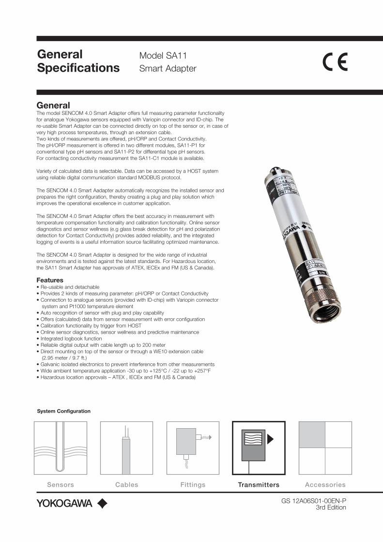
GS 12A06S01-00EN-P 3rd Edition General Specifications Sensors Cables Fittings Accessories System Configuration Transmitters Model SA11 Smart Adapter General The model SENCOM 4.0 Smart Adapter offers full measuring parameter functionality for analogue Yokogawa sensors equipped with Variopin connector and ID-chip. The re-usable Smart Adapter can be connected directly on top of the sensor or, in case of very high process temperatures, through an extension cable. Two kinds of measurements are offered, pH/ORP and Contact Conductivity. The pH/ORP measurement is offered in two different modules, SA11-P1 for conventional type pH sensors and SA11-P2 for differential type pH sensors. For contacting conductivity measurement the SA11-C1 module is available. Variety of calculated data is selectable. Data can be accessed by a HOST system using reliable digital communication standard MODBUS protocol. The SENCOM 4.0 Smart Aadapter automatically recognizes the installed sensor and prepares the right configuration, thereby creating a plug and play solution which improves the operational excellence in customer application. The SENCOM 4.0 Smart Adapter offers the best accuracy in measurement with temperature compensation functionality and calibration functionality. Online sensor diagnostics and sensor wellness (e.g glass break detection for pH and polarization detection for Contact Conductivity) provides added reliability, and the integrated logging of events is a useful information source facilitating optimized maintenance. The SENCOM 4.0 Smart Adapter is designed for the wide range of industrial environments and is tested against the latest standards. For Hazardous location, the SA11 Smart Adapter has approvals of ATEX, IECEx and FM (US & Canada). Features • Re-usable and detachable • Provides 2 kinds of measuring parameter: pH/ORP or Contact Conductivity • Connection to analogue sensors (provided with ID-chip) with Variopin connector system and Pt1000 temperature element • Auto recognition of sensor with plug and play capability • Offers (calculated) data from sensor measurement with error configuration • Calibration functionality by trigger from HOST • Online sensor diagnostics, sensor wellness and predictive maintenance • Integrated logbook function • Reliable digital output with cable length up to 200 meter • Direct mounting on top of the sensor or through a WE10 extension cable (2.95 meter / 9.7 ft.) • Galvanic isolated electronics to prevent interference from other measurements • Wide ambient temperature application -30 up to +125°C / -22 up to +257°F • Hazardous location approvals – ATEX , IECEx and FM (US & Canada)
Transcript of General Model SA11 Specifications
GS 12A06S01-00EN-P3rd Edition
GeneralSpecifications
Sensors Cables Fittings Transmitters Accessories
System Configuration
Sensors Cables Fittings Transmitters Accessories
Model SA11 Smart Adapter
General The model SENCOM 4.0 Smart Adapter offers full measuring parameter functionality for analogue Yokogawa sensors equipped with Variopin connector and ID-chip. The re-usable Smart Adapter can be connected directly on top of the sensor or, in case of very high process temperatures, through an extension cable. Two kinds of measurements are offered, pH/ORP and Contact Conductivity. The pH/ORP measurement is offered in two different modules, SA11-P1 for conventional type pH sensors and SA11-P2 for differential type pH sensors.For contacting conductivity measurement the SA11-C1 module is available.
Variety of calculated data is selectable. Data can be accessed by a HOST system using reliable digital communication standard MODBUS protocol.
The SENCOM 4.0 Smart Aadapter automatically recognizes the installed sensor and prepares the right configuration, thereby creating a plug and play solution which improves the operational excellence in customer application.
The SENCOM 4.0 Smart Adapter offers the best accuracy in measurement with temperature compensation functionality and calibration functionality. Online sensor diagnostics and sensor wellness (e.g glass break detection for pH and polarization detection for Contact Conductivity) provides added reliability, and the integrated logging of events is a useful information source facilitating optimized maintenance.
The SENCOM 4.0 Smart Adapter is designed for the wide range of industrial environments and is tested against the latest standards. For Hazardous location, the SA11 Smart Adapter has approvals of ATEX, IECEx and FM (US & Canada).
Features • Re-usable and detachable• Provides 2 kinds of measuring parameter: pH/ORP or Contact Conductivity• Connection to analogue sensors (provided with ID-chip) with Variopin connector
system and Pt1000 temperature element• Auto recognition of sensor with plug and play capability• Offers (calculated) data from sensor measurement with error configuration• Calibration functionality by trigger from HOST• Online sensor diagnostics, sensor wellness and predictive maintenance• Integrated logbook function• Reliable digital output with cable length up to 200 meter• Direct mounting on top of the sensor or through a WE10 extension cable
(2.95 meter / 9.7 ft.)• Galvanic isolated electronics to prevent interference from other measurements• Wide ambient temperature application -30 up to +125°C / -22 up to +257°F• Hazardous location approvals – ATEX , IECEx and FM (US & Canada)

2
GS 12A06S01-00EN-P
General Specifications pH/ORP/rHBasicMeasurement parameters• Temperature compensated pH/Oxidation Reduction Potential
(pH/ORP)• Temperature• Glass- and reference impedance
Note: The SENCOM 4.0 Smart Adapter can be used for analogue Yokogawa pH sensors with Variopin connector equipped with an integrated Pt1000 temperature element and integrated ID-chip.
Measurement Input SpecificationDual high impedance input (≥5x10¹² Ω) with liquid earth connection. SA11-P1 type however can operate with pH sensors with or without liquid earth.
Input signal rangepH : -2 to 16 pHORP : -1500 to +1500 mVTemperature : -40 to +260°C (-40 to +500°F)Impedance : 0.1kΩ to 10MΩ Performance (The specifications are expressed with simulated inputs).pH: Linearity : ±0.01 pH Repeatability : ±0.001 pH Accuracy : ±0.01 pH Step response (t90) : ≤ 1 sec. Ambient temp. drift : ≤ 0.0002 pH/°CORP: Linearity : ±1 mV Repeatability : ±0.1 mV Accuracy : ±1 mV Step response (t90) : ≤ 1 sec. Ambient temp. drift : ≤ 0.01 mV/°CTemperature: Linearity : ±0.3 ºC Repeatability : ±0.1 ºC Accuracy : ±0.3 ºC Step response (t90) : ≤ 1 sec. Ambient temp. drift : ≤ 0.005 °C/°CImpedance: Accuracy : ≤ 10% ± 0.3kΩ
(Calculated) output functionsThese are calculated functions using one or more input signals and/or settings. Availability of these functions depends on type of sensor.pH: ZERO, SLOPE, ITP (by 1, 2 or 3 points calibration)
Temperature compensated pH (none, process, matrix, NEN 6411)
ORP: ZERO, SLOPE (by 1 or 2 points calibration) Standard REF-, and/or pH compensated ORP
rH Temperature: Automatic (with offset compensation), manual- or
external input
Note: The SENCOM 4.0 Smart Adapter can be set by user in pH or mV for ZERO, mV/pH or percentage (%) for SLOPE and Celsius (°C) or Fahrenheit (°F) for temperature.
Contact Conductivity (SC) BasicMeasurement parameters• Conductivity/Resistivity• Temperature• Polarization
Note: The SENCOM 4.0 Smart Adapter can be used for analogue Yokogawa conductivity sensors with Variopin connector equipped with an integrated Pt1000 temperature element and integrated ID-chip.
Measurement Input SpecificationTwo/Four electrodes measurement with square wave excitation for sensors with cell constants (C.C.) from 0.005 to 50.0 cm-1.
Input signal rangeConductivity : 0 μS/cm to 250 mS x C.C.
(overrange 5000 mS/cm).Resistivity : 0.004 kΩ x C.C. to 10 MΩ x C.C.
(overrange 100 MΩ x cm)Temperature : -40 to +260°C (-40 to +500°F)
Performance (The specifications are expressed with simulated inputs, in % of reading). Conductivity: Linearity : ±0.5% Repeatability : ±0.1% (for 0...1μS/cm) : ±0.5%± 0.2nS Accuracy : ±0.5% ± 0.2nS Step response (t90) : ≤ 1 sec. (2 decades)
≤ 2 sec. (5 decades) Ambient temp. drift : ≤ 100 ppm/°CResistivity: Linearity : ±0.5% Repeatability : ±0.1% (for 1M..10MΩ/ C.C.) : ±0.5% Accuracy : ±0.5% Step response (t90) : ≤ 1 sec. (2 decades)
≤ 2 sec. (5 decades) Ambient temp. drift : ≤ 100 ppm/°CTemperature: Linearity : ±0.3 ºC Repeatability : ±0.1 ºC Accuracy : ±0.3 ºC Step response (t90) : ≤ 1 sec. Ambient temp. drift : ≤ 0.005 °C/°C
(Calculated) output functionsThese are calculated functions using one or more input signals and/or settings. Availability of these functions depends on type of sensor.Conductivity: Temperature compensated SC
(none, linear, NaCl, matrix)Resistivity: Temperature compensated RES
(none, linear, NaCl, matrix)Temperature: Automatic (with offset compensation),
manual- or external inputUSP <645>: United States Pharmacopoeia, water conductivity Concentration: e.g. Total Dissolved Solids
Note: The SENCOM 4.0 Smart Adapter can be set by user in Celsius (°C) or Fahrenheit (°F) for temperature, and in cm-1 or m-1 for Cell Constant.
3
GS 12A06S01-00EN-P
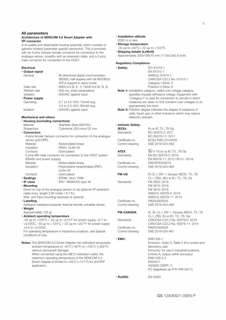
All parameters Architecture of SENCOM 4.0 Smart Adapter with VP connector A re-usable and detachable housing assembly which consists of galvanic isolated parameter specific electronics. This is provided with an 8 pins Variopin female connector for connection to the analogue sensor, possibly with an extension cable, and a 5 pins male connector for connection to the HOST.
Electrical• Output signal
General : Bi-directional digital communication (RS485, half-duplex) with full MODBUS (RTU) support in slave mode.
Data rate : 9600 b/s (8, E, 1) 19200 b/s (8, N, 2) Refresh rate : 500 ms. (main parameters) Isolation : 500VAC against input• Power supply
Operating : 2.7 to 4.5 VDC /15mW avg. 4.5 to 5.5 VDC /65mW avg.
Isolation : 500VAC against input
Mechanical and others• Housing (excluding connectors)
Material : Stainless Steel (SS316L) Shape/size : Cylindrical, Ø21mmx122 mm
• Connectors - 8-pins female Variopin connector for connection to the analogue
sensor (pH/ORP). Material : Nickel-plated brass Insulation : PEEK, UL94-V0 Contacts : Gold-plated
- 5-pins M9 male connector for connection to the HOST system (RS485 and power supply). Material : Nickel-plated brass Insulation : Polybutylene terephthalate (PBT),
UL94-V0Contacts : Gold-plated
• Sealings : EPDM, Viton, FKM• IP class : IP67, NEMA250 type 4X• Mounting
Direct on top of the analogue sensor or via optional VP extension cable (max. length 2.95 meter / 9.7 ft.); Wall- and Pipe mounting hardware is optional.
• Labelling Adhesive metalized polyester thermal transfer printable sticker.
• Weight Approximately 125 gr.
• Ambient operating temperature -30 up to +100°C / -22 up to +212°F for power supply +2.7 to +4.5VDC, -30 up to +125°C / -22 up to +257°F for power supply +4.5 to +5.5VDC For operating temperature in hazardous locations, see Special conditions of Use.
Notes: The SENCOM 4.0 Smart Adapter can withstand temporarily
ambient temperature to -40°C (-40°F) or +150°C (+302°F) without permanent damage; When connected using the WE10 extension cable, the maximum operating temperature of the SENCOM 4.0 Smart Adapter is limited to +55°C (+131°F) for pH/ORP application.
• Installation altitude 2000 m or less• Storage temperature
-30 up to +50°C (-22 up to +122°F)• Shipping details (LxWxH)
Approximately 300x100x75 mm (11.8x3.9x2.9 inch)
Regulatory Compliance• Safety: IEC 61010-1
EN 61010-1 ANSI/UL 61010-1 CAN/CSA C22.2 No. 61010-1
Category I (Note 1) Pollution 2 (Note 2) Note 1: Installation category, called over-voltage category,
specifies impulse withstand voltage. Equipment with “Category I” is used for connection to circuits in which measures are taken to limit transient over-voltages to an appropriately low level.
Note 2: Pollution degree indicates the degree of existence of solid, liquid, gas or other inclusions which may reduce dielectric strength.
• Intrinsic Safety: IECEx Ex ia IIC T3...T6 Ga
Standards: IEC 60079-0: 2017 IEC 60079-11: 2011 Certificate no. IECEx FMG 20.0003X Control drawing D&E 2019-024-A62
ATEX II 1G Ex ia IIC T3...T6 Ga Standards: EN IEC 60079-0: 2018 EN 60079-11: 2012 (/IS 01: 2014) Certificate no. FM20ATEX0001X Control drawing D&E 2019-024-A62
FM-US IS CL I, DIV 1, Groups ABCD, T3...T6 CL I, ZN0, AEx ia IIC, T3...T6, Ga Standards: FM 3600: 2018 FM 3610: 2018 FM 3810: 2018 ANSI/UL 60079-0: 2019 ANSI/UL 60079-11: 2014 Certificate no. FM20US0004X Control drawing D&E 2019-024-A60
FM-CANADA IS, SI, CL I, DIV 1, Groups ABCD, T3...T6 CL I, ZN0, Ex ia IIC, T3...T6, Ga Standards: CAN/CSA-C22.2 No. 60079-0: 2019 CAN/CSA-C22.2 No. 60079-11: 2014 Certificate no. FM20CA0002X Control drawing D&E 2019-024-A61
• EMC: EN61326-1 Emission: Class A, Table 2 (For control and laboratory use) Immunity: for use in industrial locations, (criteria A, output within accuracy) EN61326-2-3
EN55011 AS/NZS CISPR 11 KC (registered as R-R-YPA-SA11)
• RoHS2: EN 50581

4
GS 12A06S01-00EN-P
Special conditions of Use
WARNING
Potential electrostatic charging hazard – When the equipment is used in hazardous locations, avoid any actions which generate electrostatic discharge, such as rubbing with a dry cloth.
AVERTISSEMENT
Risque potentiel de charge électrostatique - Lorsque l’équipement est utilisé dans des zones dangereuses, évitez toute action générant une décharge électrostatique, comme un frottement avec un chiffon sec.
WARNING
The Input Port connections incorporate an earthed conductor. Care shall be taken to prevent ignition-capable earth currents resulting from differing earth potentials between the SA11 and Host. Refer to section 5-3 for instructions concerning earthing and isolation of the SA11.
AVERTISSEMENT
Les connexions du port d’entrée comportent un conducteur mis à la terre. Des précautions doivent être prises pour éviter les courants de terre capables d’allumage résultant de potentiels de terre différents entre le SA11 et l’hôte. Reportez-vous à la section 5-3 pour les instructions concernant la mise à la terre et l’isolement du SA11.
Ambient temperature conditions depend on the temperature class:T6: -30°C ≤ Ta ≤ +40°CT5: -30°C ≤ Ta ≤ +60°C T4: -30°C ≤ Ta ≤ +80°CT3: -30°C ≤ Ta ≤ +80°C
Model & Suffix Codes
Model Suffix code Option code DescriptionSA11 SENCOM Smart AdapterMeasuring Parameter -P1 pH/ORP, conventional -P2 pH/ORP, differential -C1 Specific ConductivityType -AA General purpose -CB IS for ATEX, IECEx -CD IS for FM-US, FM-CanadaRegion -N Not specifiedConnection type -VS Variopin connector for SENCOM ID-chip in sensorStyle -NN Always -NNOption /UM Pipe and wall mounting hardware
Notes: Code -P1 is for conventional pH/ORP, to be used with pH sensors with standard (non)flowing reference system; Code -P2 is for differential pH/ORP, to be used with salt sensitive reference system; Option /UM can be ordered as part of modelcode or as spare part K1548PQ.
Spareparts
Order no. Product Name Quantity RemarkK1548PQ Universal mounting set 1 set Option /UMK1548GF O-ring set (5 pieces) 1 set
Option /UM contains Pipe and Wall mounting hardware
5
GS 12A06S01-00EN-P
Yokogawa Process Analyzers Europe B.V. Model SA11
Title FM Control Drawing – United States Author T. Both Approval S. Kiyono
No. D&E 2019-024-A60
Page 1 Revision 1 Date 2020-02-03
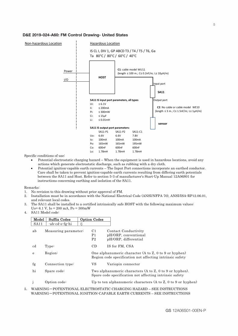
Specific conditions of use: • Potential electrostatic charging hazard – When the equipment is used in hazardous locations, avoid any
actions which generate electrostatic discharge, such as rubbing with a dry cloth. • Potential ignition-capable earth currents – The Input Port connections incorporate an earthed conductor.
Care shall be taken to prevent ignition-capable earth currents resulting from differing earth potentials between the SA11 and Host. Refer to section 5-3 of manufacturer’s Start-Up Manual 12A06S01 for instructions concerning earthing and isolation of the SA11.
Remarks: 1. No revision to this drawing without prior approval of FM. 2. Installation must be in accordance with the National Electrical Code (ANSI/NFPA 70), ANSI/ISA-RP12.06.01,
and relevant local codes. 3. The SA11 shall be installed to a certified intrinsically safe HOST with the following maximum values:
Uo= 6.1 V, Io = 200 mA, Po = 300mW 4. SA11 Model code:
MMooddeell SSuuffffiixx CCooddeess OOppttiioonn CCooddeess SA11 -ab-cd-e-fg-hi /j
ab Measuring parameter: C1 Contact Conductivity P1 pH/ORP, conventional P2 pH/ORP, differential cd Type: CD IS for FM, CSA e Region: One alphanumeric character (A to Z, 0 to 9 or hyphen) Region code specification not affecting intrinsic safety fg Connection type: VS Variopin connector hi Spare code: Two alphanumeric characters (A to Z, 0 to 9 or hyphen).
Spare code specification not affecting intrinsic safety
j Option code: Up to ten alphanumeric characters (A to Z, 0 to 9 or hyphen)
5. WARNING-POTENTIONAL ELECTROSTATIC CHARGING HAZARD – SEE INSTRUCTIONS WARNING-POTENTIONAL IGNITION-CAPABLE EARTH CURRENTS – SEE INSTRUCTIONS
Non-hazardous Location Hazardous Location
IS CL I, DIV 1, GP ABCD T3 / T4 / T5 / T6, GaTa 80°C / 80°C / 60°C / 40°C
Power
I/OInput port
SA11 IS input port parameters, all types Output portUi: ≤ 6.1VIi: ≤ 200mAPi: ≤ 300mWCi: ≤ 15μFLi: ≤ 0.01mH
SA11 IS output port parameters:SA11-P1 SA11-P2 SA11-C1
Uo: 6.6V 6.6V 7.8VIo: 100mA 100mA 100mAPo: 165mW 165mW 195mWCo: 600nF 600nF 600nFLo: 1.78mH 1.78mH 1.78mH
HOST
C2: No cable or cable model WE10(length ≤ 3 m.; C≤ 1.5nF/m; L≤ 1μH/m)
C1: cable model WU11(length ≤ 100 m.; C≤ 0.2nF/m; L≤ 10μH/m)
SA11
sensor
D&E 2019-024-A60: FM Control Drawing- United States

6
GS 12A06S01-00EN-P
Yokogawa Process Analyzers Europe B.V. Model SA11
Title FM Control Drawing – Canada Author T. Both Approval S. Kiyono
No. D&E 2019-024-A61
Page 1 Revision 1 Date 2020-02-03
Specific conditions of use:
• Potential electrostatic charging hazard – When the equipment is used in hazardous locations, avoid any actions which generate electrostatic discharge, such as rubbing with a dry cloth.
• Potential ignition-capable earth currents – The Input Port connections incorporate an earthed conductor. Care shall be taken to prevent ignition-capable earth currents resulting from differing earth potentials between the SA11 and Host. Refer to section 5-3 of manufacturer’s Start-Up Manual 12A06S01 for instructions concerning earthing and isolation of the SA11.
Remarks: 1. No revision to this drawing without prior approval of FM. 2. Installation must be in accordance with Canadian Electrical Code (CEC) CSA C22.1, and relevant local codes. 3. The SA11 shall be installed to a certified intrinsically safe HOST with the following maximum values:
Uo = 6.1 V, Io = 200 mA, Po = 300mW 4. SA11 Model code:
MMooddeell SSuuffffiixx CCooddeess OOppttiioonn CCooddeess SA11 -ab-cd-e-fg-hi /j
ab Measuring parameter: C1 Contact Conductivity P1 pH/ORP, conventional P2 pH/ORP, differential
cd Type: CD IS for FM, CSA
e Region: One alphanumeric character (A to Z, 0 to 9 or hyphen) Region code specification not affecting intrinsic safety
fg Connection type: VS Variopin connector hi Spare code: Two alphanumeric characters (A to Z, 0 to 9 or hyphen).
Spare code specification not affecting intrinsic safety
j Option code: Up to ten alphanumeric characters (A to Z, 0 to 9 or hyphen)
5. WARNING-POTENTIONAL ELECTROSTATIC CHARGING HAZARD – SEE INSTRUCTIONS AVERTISSEMENT – DANGER POTENTIEL DE CHARGES ÉLECTROSTATIQUES – VOIR LES INSTRUCTIONS
WARNING-POTENTIONAL IGNITION-CAPABLE EARTH CURRENTS – SEE INSTRUCTIONS AVERTISSEMENT-COURANTS DE TERRE POTENTIONNELS CAPABLES À L'ALLUMAGE – VOIR LES INSTRUCTIONS
Non-hazardous Location Hazardous Location
IS, SI, CL I, DIV 1, GP ABCD T3 / T4 / T5 / T6, GaTa 80°C / 80°C / 60°C / 40°C
Power
I/OInput port
SA11 IS input port parameters, all types Output portUi: ≤ 6.1VIi: ≤ 200mAPi: ≤ 300mWCi: ≤ 15μFLi: ≤ 0.01mH
SA11 IS output port parameters:SA11-P1 SA11-P2 SA11-C1
Uo: 6.6V 6.6V 7.8VIo: 100mA 100mA 100mAPo: 165mW 165mW 195mWCo: 600nF 600nF 600nFLo: 1.78mH 1.78mH 1.78mH
HOST
C2: No cable or cable model WE10(length ≤ 3 m.; C≤ 1.5nF/m; L≤ 1μH/m)
C1: cable model WU11(length ≤ 100 m.; C≤ 0.2nF/m; L≤ 10μH/m)
SA11
sensor
D&E 2019-024-A61: FM Control Drawing- Canada
7
GS 12A06S01-00EN-P
Yokogawa Process Analyzers Europe B.V. Model SA11
Title ATEX/IECEx Control Drawing Author T. Both Approval S. Kiyono
No. D&E 2019-024-A62
Page 1 Revision 1 Date 2020-02-03
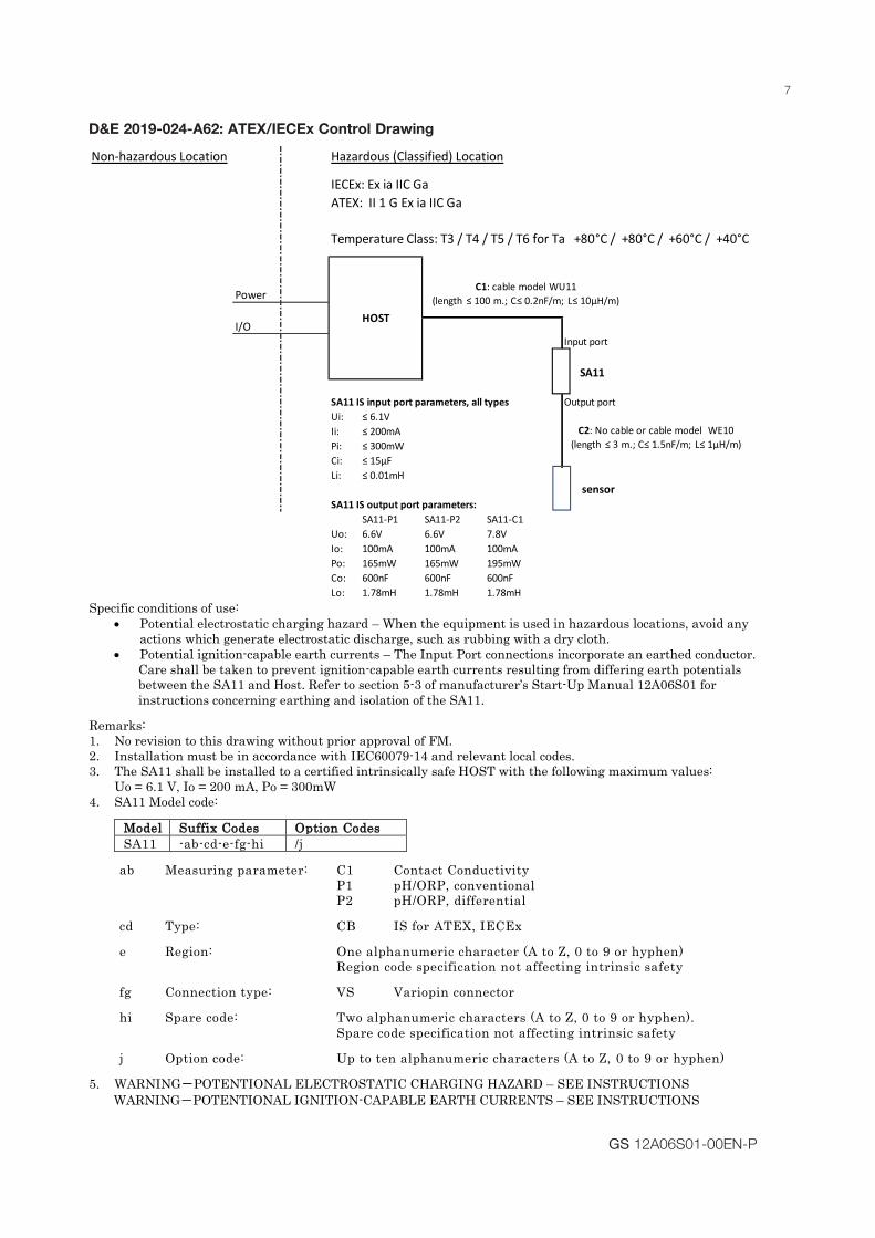
Specific conditions of use:
• Potential electrostatic charging hazard – When the equipment is used in hazardous locations, avoid any actions which generate electrostatic discharge, such as rubbing with a dry cloth.
• Potential ignition-capable earth currents – The Input Port connections incorporate an earthed conductor. Care shall be taken to prevent ignition-capable earth currents resulting from differing earth potentials between the SA11 and Host. Refer to section 5-3 of manufacturer’s Start-Up Manual 12A06S01 for instructions concerning earthing and isolation of the SA11.
Remarks: 1. No revision to this drawing without prior approval of FM. 2. Installation must be in accordance with IEC60079-14 and relevant local codes. 3. The SA11 shall be installed to a certified intrinsically safe HOST with the following maximum values:
Uo = 6.1 V, Io = 200 mA, Po = 300mW 4. SA11 Model code:
MMooddeell SSuuffffiixx CCooddeess OOppttiioonn CCooddeess SA11 -ab-cd-e-fg-hi /j
ab Measuring parameter: C1 Contact Conductivity P1 pH/ORP, conventional P2 pH/ORP, differential cd Type: CB IS for ATEX, IECEx e Region: One alphanumeric character (A to Z, 0 to 9 or hyphen) Region code specification not affecting intrinsic safety fg Connection type: VS Variopin connector hi Spare code: Two alphanumeric characters (A to Z, 0 to 9 or hyphen).
Spare code specification not affecting intrinsic safety
j Option code: Up to ten alphanumeric characters (A to Z, 0 to 9 or hyphen)
5. WARNING-POTENTIONAL ELECTROSTATIC CHARGING HAZARD – SEE INSTRUCTIONS WARNING-POTENTIONAL IGNITION-CAPABLE EARTH CURRENTS – SEE INSTRUCTIONS
Non-hazardous Location Hazardous (Classified) Location
Temperature Class: T3 / T4 / T5 / T6 for Ta +80°C / +80°C / +60°C / +40°C
Power
I/OInput port
SA11 IS input port parameters, all types Output portUi: ≤ 6.1VIi: ≤ 200mAPi: ≤ 300mWCi: ≤ 15μFLi: ≤ 0.01mH
SA11 IS output port parameters:SA11-P1 SA11-P2 SA11-C1
Uo: 6.6V 6.6V 7.8VIo: 100mA 100mA 100mAPo: 165mW 165mW 195mWCo: 600nF 600nF 600nFLo: 1.78mH 1.78mH 1.78mH
HOST
IECEx: Ex ia IIC GaATEX: II 1 G Ex ia IIC Ga
C2: No cable or cable model WE10(length ≤ 3 m.; C≤ 1.5nF/m; L≤ 1μH/m)
C1: cable model WU11(length ≤ 100 m.; C≤ 0.2nF/m; L≤ 10μH/m)
SA11
sensor
D&E 2019-024-A62: ATEX/IECEx Control Drawing

GS 12A06S01-00EN-PSubject to change without notice Printed in The Netherlands, 03-2006
YOKOGAWA EUROPE B.V.Euroweg 23825 HD AMERSFOORTThe NetherlandsTel. +31-88-4641 000Fax +31-88-4641 111E-mail: [email protected]/eu
YOKOGAWA CORPORATION OF AMERICA2 Dart RoadNewnan GA 30265United StatesTel. (1)-770-253-7000Fax (1)-770-251-2088www.yokogawa.com/us
YOKOGAWA ELECTRIC ASIA Pte. Ltd.5 Bedok South RoadSingapore 469270SingaporeTel. (65)-241-9933Fax (65)-241-2606www.yokogawa.com/sg
YOKOGAWA HEADQUARTERS9-32, Nakacho 2-chome,MusashinoshiTokyo 180JapanTel. (81)-422-52-5535Fax (81)-422-55-1202www.yokogawa.com
Yokogawa has an extensive sales and distribution network. Please refer to the European website (www.yokogawa.com/eu) to contact your nearest representative.
Min ø45 [1.77]
Pipe not included
[0.71]
18 Appr.
Pipe not included
Max ø60 [2.36] [0.43]
11
[1.98]50
[1.1
8]30
[1.93]49
[2.8]71
[3.94]100
[2.3
6]60
[1.97]50
[1.1
8]30
[3.94]100
[2.3
6]60
[1.3]33
[1.97]50
• SENCOM 4.0 Smart Adapter mounted with optional wall- and pipe mounting hardware (/UM)
Wall mounting Pipe mounting
0.78
Dimensions in [inches]; mm
SENCOM® Smart Adapter mounted by extension cable on top of sensor
Note: SA11-P1 to be used in combination with WE10-H-D-003-V1 cable;SA11-P2 and SA11-C1 to be used in combination with WE10-H-D-003-V2 cable
Dimensions and Mounting
Dimensions in [inches]; mm
SENCOM® Smart Adapter mounted directly on top of sensor.