General Model RAGL Specifications...
8
General Specifications Model RAGL Rotameter This type of Rotameter is designed for measurement of liquids and gases. The conical glass metering tube has a free rotating float. This float is mounted in a vertical pipeline with flow direction upwards. The flow is indicated by the top of the float and can be read from the standard scale on the metering tube or from a connected scale. When the process conditions are changed the scale needs to be replaced by a new one of which the values should be calculated. FEATURES - Large selection of measuring ranges - Anti-static metering tubes for measurement of small quantities of gas - High accuracy of free rotating float even at low flow rates - Low pressure loss - Visual check of the medium - Non-powered local indication - Large selection of scales - Optional built-in valve - Exact scale calculation at changed process conditions according to VDE/VDI guidelines 3513 with the use of the flow table (option /PT) STANDARD SPECIFICATIONS Measurable flow rates - Water (20 °C) : 0.002 l/h bis 110 l/h - Air (20 °C ; 1 bar abs.): 0.1 l/h bis 3 500 l/h Measuring range - K metering tube : 10:1 - M metering tube : 20:1 (10:1) - L metering tube : 20:1 Metering tubes : K6; M6; L6; K7; R7; M7; L7 Accuracy Max. Temperature - Fitting material SS : 100 °C - With option /MV : 130 °C (not for PP-Rotameter) - Fitting material PP : 80 °C Max. Pressure : 16 bar Material process connection - Inner thread : PP or 1.4581 (for option controller 1.4571) - Cutting ring : 1.4571 or steel - Nozzle : 1.4571or steel (PTFE) - Swageloc connection : 1.4571 Material of fitting : Polypropylen; 1.4581 Material of gaskets : PE / Buna (for M-, K-, R- tube) PTFE / Buna (for L-tube) - With option /MV : PTFE / Viton Design (valve) : with or without built-in valve Length approx. : 100 mm; 175 mm or 325 mm Weight : depending on design 0.3 to 1.3 kg (without stand and controller) with K-metering tube with M-metering tube with L-metering tube T1.EPS Glass Metering Tube Length Accuracy class acc. VDE / VDI 3513 R741 - R743 K631 - K743 M613 - M622 M624 - M747 L613 - L623 L624 - L747 75mm 75mm 150mm 150mm 300mm 300mm 6 (only with ball) 4 (for ball 6) 4 , better on request 2.5 , better on request 2.5 , better on request 1.6 , better on request Standard flow accuracy: full scale ± 6 % ± 4 % (± 6 %) ± 4 % ± 2.5 % ± 2.5 % ± 1.6 % GS 01R01B08-00E-E Copyright 2004 6th edition, April 2007 Rota Yokogawa GmbH & Co. KG Rheinstr. 8 D-79664 Wehr Germany
Transcript of General Model RAGL Specifications...
GeneralSpecifications
Model RAGLRotameter
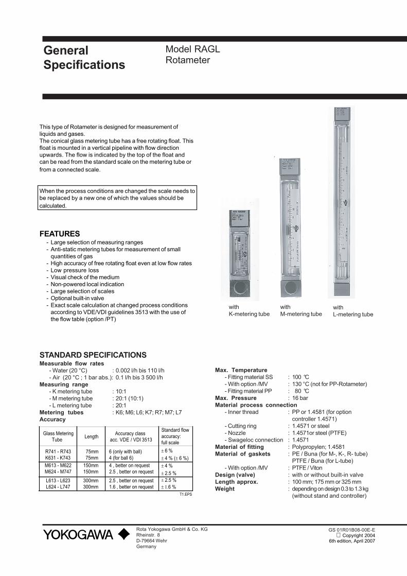
This type of Rotameter is designed for measurement ofliquids and gases.The conical glass metering tube has a free rotating float. Thisfloat is mounted in a vertical pipeline with flow directionupwards. The flow is indicated by the top of the float andcan be read from the standard scale on the metering tube orfrom a connected scale.
When the process conditions are changed the scale needs tobe replaced by a new one of which the values should becalculated.
FEATURES- Large selection of measuring ranges- Anti-static metering tubes for measurement of small
quantities of gas- High accuracy of free rotating float even at low flow rates- Low pressure loss- Visual check of the medium- Non-powered local indication- Large selection of scales- Optional built-in valve- Exact scale calculation at changed process conditions
according to VDE/VDI guidelines 3513 with the use ofthe flow table (option /PT)
STANDARD SPECIFICATIONSMeasurable flow rates
- Water (20 °C) : 0.002 l/h bis 110 l/h- Air (20 °C ; 1 bar abs.): 0.1 l/h bis 3 500 l/h
Measuring range- K metering tube : 10:1- M metering tube : 20:1 (10:1)- L metering tube : 20:1
Metering tubes : K6; M6; L6; K7; R7; M7; L7Accuracy
Max. Temperature- Fitting material SS : 100 °C- With option /MV : 130 °C (not for PP-Rotameter)- Fitting material PP : 80 °C
Max. Pressure : 16 barMaterial process connection
- Inner thread : PP or 1.4581 (for optioncontroller 1.4571)
- Cutting ring : 1.4571 or steel- Nozzle : 1.4571or steel (PTFE)- Swageloc connection : 1.4571
Material of fitting : Polypropylen; 1.4581Material of gaskets : PE / Buna (for M-, K-, R- tube)
PTFE / Buna (for L-tube)- With option /MV : PTFE / Viton
Design (valve) : with or without built-in valveLength approx. : 100 mm; 175 mm or 325 mmWeight : depending on design 0.3 to 1.3 kg
(without stand and controller)
withK-metering tube
withM-metering tube
withL-metering tube
T1.EPS
Glass Metering Tube
Length Accuracy class
acc. VDE / VDI 3513
R741 - R743K631 - K743M613 - M622M624 - M747
L613 - L623L624 - L747
75mm 75mm150mm150mm
300mm300mm
6 (only with ball)4 (for ball 6)4 , better on request2.5 , better on request
2.5 , better on request1.6 , better on request
Standard flowaccuracy:full scale
± 6 %± 4 % (± 6 %) ± 4 % ± 2.5 % ± 2.5 %± 1.6 %
GS 01R01B08-00E-E Copyright 2004
6th edition, April 2007
Rota Yokogawa GmbH & Co. KGRheinstr. 8D-79664 WehrGermany
2
TECHNICAL DATA OF OPTIONS
LIMIT SWITCH (OPTION /GI1 to /GI4)(For floats of Mumetall or PVDF with Fe-core only andQmin > 0.004 l/h water or 0.3 l/h air)Type : Bistable inductive ring sensorPower supply : 4.5 V to 15 V DCConsumption : acc. DIN EN 60947-5-6 (NAMUR)For floatbelow ring sensor : < 1mAabove ring sensor : > 2.2 mATemperature range : -25°C bis +70°C not Ex-typeProtection : IP 67Electrical connection: 2 x 0.14 mm² ,
with shield 0.4 mm², 2 m longEMC :DIN EN 61000-4-2 : level 3DIN EN 61000-4-3 : level 2DIN EN 61000-4-4 : level 3DIN EN 61000-4-6 : level 2DIN EN 55011 : group 1 / class AIn general the RI20 complies with the above given criteria.However, in certain situations the switch may react from“off” to “on”. In such cases the customer has to assure byhimself that this does not happen. Normally the behavior canbe improved by more distance to the EMC-source or by usinga different cable position.
EXPLOSION PROOF (OPTION /KS1)Temperature range :-25°C to +60°CMarking acc. guideline 94/9/EG :Manufacturer : Rota Yokogawa, Rheinstr.8,
D-79664 WehrType : RI20-10K/G or RI20-17K/GYear of production : in serial numberProtection : EEx iaGroup : IICCategory : 1Explosive atmosphere : GTemperature class : T6Certificate No. : PTB 03 ATEX 2111Safety relevant data : Ui = 12V, Ii = 22mA , Pi = 66mW,
Li = 20mH, Ci = 200nF or see certificate for data
CE-marking : II 2 G
POWER SUPPLY FOR LIMIT SWITCH(OPTION /W__)Type : Transmitter relay acc.
DIN EN 60947-5-6 (NAMUR)Power supply : 230V AC (/W2_)
115V AC (/W1_)24V DC (/W4_)
Switching capacity : max. 250 V AC; max. 4Aor max. 500 VA
Relay output : 1 or 2 potential free changeovercontacts
Explosion proof : Intrinsic safe [EEx ia] II Cacc. PTB 00 ATEX 2081 (/W2_)acc. PTB 00 ATEX 2080 (/W4_)
CONTROLLER (OPTION /R1 and /R3)Differential pressure controller for a constant flow atfluctuations of the back pressure.These are no pressure limiting valves.- The controller /R1is for liquids with variable inlet or outletpressure and for gases with variable inlet pressure andconstant back pressure.- The controller /R3 is for gases with fluctuations of theback pressure.Max. liquid flow : 100 l/hMax. gas flow : 3000 l/hMax. temperature : 80°CRecommended differential pressure : > 400 mbar
Materials
Housing Membrane SpringsCrNi-steel PTFE CrNi-steel
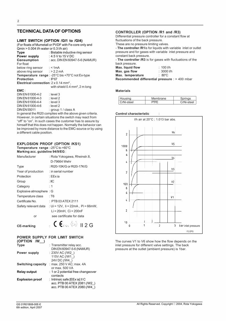
Control characteristic :
F2.EPS
inlet pressure
The curves V1 to V6 show how the flow depends on theinlet pressure for different valve settings. The backpressure at the outlet (ambient pressure) is 1bar.
l/h air at 20°C ; 1.013 bar abs.
GS 01R01B08-00E-E6th edition, April 2007
All Rights Reserved. Copyright 2004, Rota Yokogawa

3
GS 01R01B08-00E-E6th edition, April 2007
All Rights Reserved. Copyright 2004, Rota Yokogawa
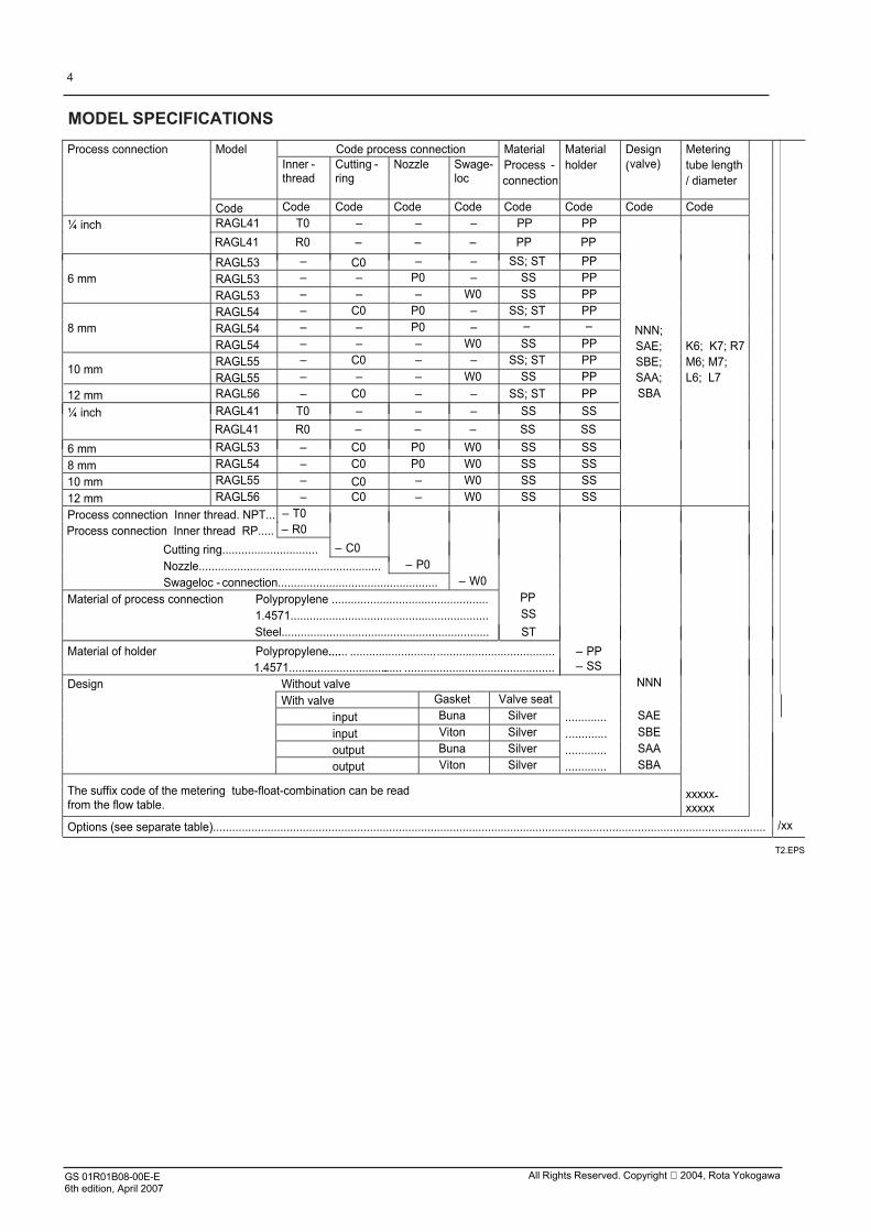
MODEL SPECIFICATIONS
4
Code process connectionModelInner -thread
Cutting -ring
Nozzle Swage-loc
MaterialProcess -connection
Materialholder
Design(valve)
Meteringtube length/ diameter
Process connection
Code Code Code Code Code Code Code Code Code
¼ inch RAGL41 T0 – – – PP PP
RAGL53 – C0 – – SS; ST PP
RAGL53 – – P0 – SS PP6 mmRAGL53 – – – W0 SS PP
RAGL54 – C0 P0 – SS; ST PP
RAGL54 – – P0 –8 mmRAGL54 – – – W0 SS PP
RAGL55 – C0 – – SS; ST PP10 mm
RAGL55 – – – W0 SS PP
12 mm RAGL56 – C0 – – SS; ST PP
¼ inch RAGL41 T0 – – – SS SS
NNN;SAE;SBE;SAA;SBA
K6; K7; R7M6; M7;L6; L7
T2.EPS
6 mm RAGL53 – C0 P0 W0 SS SS
8 mm RAGL54 – C0 P0 W0 SS SS
10 mm RAGL55 – C0 – W0 SS SS
12 mm RAGL56 – C0 – W0 SS SS
Process connection Inner thread. NPT... – T0
Cutting ring.............................. – C0
Nozzle......................................................... – P0
Swageloc - connection.................................................. – W0
Material of process connection Polypropylene ................................................. PP
1.4571.............................................................. SS
Steel................................................................. ST
Material of holder Polypropylene.......... ................................................................ – PP1.4571...................................... ............................................... – SS
Without valve NNN
With valve Gasket Valve seat
input Buna Silver ............. SAE
input Viton Silver ............. SBE
output Buna Silver ............. SAA
Design
output Viton Silver ............. SBA
The suffix code of the metering tube-float-combination can be readfrom the flow table.
xxxxx-xxxxx
Options (see separate table)............................................................................................................................................................................. /xx
– –
RAGL41 R0 – – – SS SS
RAGL41 R0 – – – PP PP
Process connection Inner thread RP..... – R0
GS 01R01B08-00E-E6th edition, April 2007
All Rights Reserved. Copyright 2004, Rota Yokogawa

Flow tables with metering tube- float combination for water / liquids
5
Flow table Suffix code metering tube-float-combinationWater 20°C / Liquid Tube Float
Recommended comb.Row 1
Alternative comb..Row 2 – X X XX X – XX X X X
Max.Flow
Pressure-loss *)
Max.Flow
Pressure -loss *) Length Diameter Tube
Cone Scale Material Diameter Flow-mark Insertion
[l/h] [mbar] [l/h] [mbar] Code Code Code Code Code Code Code Code1 2 – – K 6 315 3 – – K 6 334 4 – – K 6 346 8 – – K 6 37
B
10 4 – – K 7 4115 5 – – K 7 4226 6 – – K 7 43
C
40 5 – – K 7 4463 8 – – K 7 47
110 10 – – K 7 51
Row 1SS; MU 1)
D
0.025 1 0.054 2 M 6 130.063 2 0.15 3 M 6 17
Row 1TT; KR
0.16 3 0.36 4 M 6 22Row 2
SS; MU1)A
0.4 1 0.8 2 M 6 241 2 2 3 M 6 31
1.6 3 2.8 3 M 6 322.5 4 4 4 M 6 333.5 5 6 8 M 6 35
B
4 2 6.3 4 M 7 34
Row 1TT; KR;
PD1)
6.3 3 10 5 M 7 3710 3 16 5 M 7 4116 4 27 6 M 7 4225 5 44 6 M 7 43
C
40 5 66 8 M 7 4463 10 100 10 M 7 47
Row 2SS; MU1)
D
0.025 1 0.054 2 L 6 130.04 1 0.074 2 L 6 14
0.063 2 0.15 3 L 6 170.1 2 0.23 3 L 6 21
Row 1TT; KR
0.16 3 0.36 4 L 6 220.25 4 0.54 5 L 6 23
Row 2SS; MU1)
A
0.4 1 0.8 2 L 6 240.63 1 1.2 2 L 6 27
1 2 2 3 L 6 311.6 3 2.8 3 L 6 322.5 4 4 4 L 6 33
B
4 2 6.3 4 L 7 34
Row 1TT; KR;
PD1)
6.3 2 10 4 L 7 3710 3 16 5 L 7 4116 4 27 6 L 7 4225 5 44 6 L 7 43
C
40 5 66 8 L 7 4463 10 110 10 L 7 47
G;A;N
Row 2SS; MU1)
D
L N
Tube length (type) 75 mm.................... K150 mm................... M300 mm.................... L
Tube diameter 10 mm; 17 mm........................ XTube cone See flow table.......................................... X
Scale on tube and mm-division....................................2) GConnection scale and mm- division (recommended)... A
Tube medium scale
Metering tube with mm- division only........................... N1.4571......................................................................................... SSTitanium............................................................................................ TT
MUPD
Float material
Corundum........................................................................................ KR
Float diameter XFlow mark LFloat insertion ......... N
2)
*) The indicated flow drop is a pilot value and may deviate based on the type of Rotameter.
T3.EPS1) For option limit switch /GI1 to /GI4 Select option /MM if no mm-division is required
Without magnet..................................................................................................................................Liquid..................................................................................................................................
Mumetal (for limit switch /GI1; /GI2 and /GI4).............................PVDF (for limit switch /GI2 to /GI4)...........................................
1.6 mm to 9 mm.................................................................................................
Additional tube-float-combinations with different float materials and different measuring ranges are available on request.If the Rotameter should be used in other media- / process- conditions use the sizing software DUREP-v.
10 4 – – R 7 4116 4 – – R 7 4225 5 – – R 7 4340 5 – – R 7 4463 6 – – R 7 47
100 6 – – R 7 51
C
D
SR
3)
3)
3) Max. viscosity is 2 mPas*s
CrNi-ball........................................................................................ SR
GS 01R01B08-00E-E6th edition, April 2007
All Rights Reserved. Copyright 2004, Rota Yokogawa
6
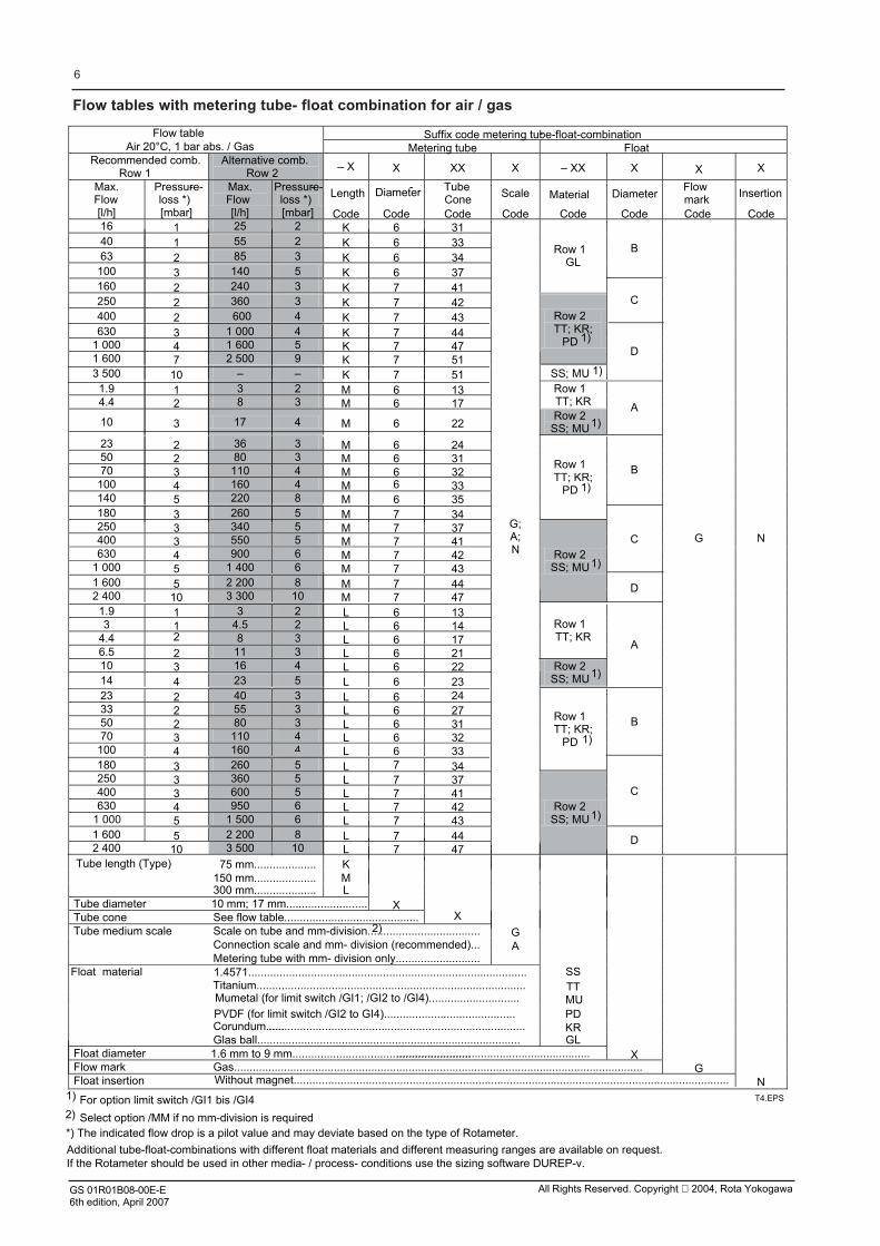
Flow tables with metering tube- float combination for air / gas
Flow table Suffix code metering tube-float-combination-Air 20°C, 1 bar abs. / Gas Metering tube Float
Recommended comb.Row 1
Alternative comb.Row 2 – X X XX X – XX X X X
Max.Flow
Pressure--loss *)
Max.Flow
Pressure--loss *) Length Diameter- Tube
Cone Scale Material DiameterFlowmark Insertion
[l/h] [mbar] [l/h] [mbar] Code Code Code Code Code Code Code Code16 1 25 2 K 6 3140 1 55 2 K 6 3363 2 85 3 K 6 34
100 3 140 5 K 6 37
B
160 2 240 3 K 7 41
Row 1GL
250 2 360 3 K 7 42400 2 600 4 K 7 43
C
630 3 1 000 4 K 7 441 000 4 1 600 5 K 7 471 600 7 2 500 9 K 7 51
Row 2TT; KR;
PD 1)
3 500 10 – – K 7 51 SS; MU 1)
D
1.9 1 3 2 M 6 134.4 2 8 3 M 6 17
Row 1TT; KR
10 3 17 4 M 6 22Row 2
SS; MU1)A
23 2 36 3 M 6 2450 2 80 3 M 6 3170 3 110 4 M 6 32
100 4 160 4 M 6 33140 5 220 8 M 6 35
B
180 3 260 5 M 7 34
Row 1TT; KR;
PD 1)
250 3 340 5 M 7 37400 3 550 5 M 7 41630 4 900 6 M 7 42
1 000 5 1 400 6 M 7 43
C
1 600 5 2 200 8 M 7 442 400 10 3 300 10 M 7 47
Row 2SS; MU1)
D
1.9 1 3 2 L 6 133 1 4.5 2 L 6 14
4.4 2 8 3 L 6 176.5 2 11 3 L 6 21
Row 1TT; KR
10 3 16 4 L 6 2214 4 23 5 L 6 23
Row 2SS; MU1)
A
23 2 40 3 L 6 2433 2 55 3 L 6 2750 2 80 3 L 6 3170 3 110 4 L 6 32
100 4 160 4 L 6 33
B
180 3 260 5 L 7 34
Row 1TT; KR;
PD 1)
250 3 360 5 L 7 37400 3 600 5 L 7 41630 4 950 6 L 7 42
1 000 5 1 500 6 L 7 43
C
1 600 5 2 200 8 L 7 442 400 10 3 500 10 L 7 47
G;A;N
Row 2SS; MU1)
D
G N
75 mm.................... K150 mm.................... M300 mm.................... L
Tube diameter 10 mm; 17 mm.......................... XTube cone See flow table........................................... X
Scale on tube and mm-division....................................2) GConnection scale and mm- division (recommended)... A
Tube medium scale
Metering tube with mm- division only...........................SSTT
PDCorundum........................................................................................ KR
Float material
Glas ball.................................................................................... GLFloat diameter .............................................................. XFlow mark Gas................................................................................................................................... GFloat insertion N
1)
2)
*) The indicated flow drop is a pilot value and may deviate based on the type of Rotameter.
T4.EPSFor option limit switch /GI1 bis /GI4
Without magnet...........................................................................................................................................
1.6 mm to 9 mm.........................................................
Titanium......................................................................................1.4571.........................................................................................
Tube length (Type)
MU
Select option /MM if no mm-division is required
Mumetal (for limit switch /GI1; /GI2 to /GI4).............................PVDF (for limit switch /GI2 to GI4)..........................................
Additional tube-float-combinations with different float materials and different measuring ranges are available on request.If the Rotameter should be used in other media- / process- conditions use the sizing software DUREP-v.
GS 01R01B08-00E-E6th edition, April 2007
All Rights Reserved. Copyright 2004, Rota Yokogawa
OPTIONS
7
T5.EPS
Options Option code Description
Marking /B1/B4/B8/BG
Tag plate (SS) Neutral versionCustomer provided marking on labelCustomer specific notes on scale
Restrictions
Plate 12 x 40 mm; max. 45 digits
Limit switches /GI1/GI2/GI3/GI4
Bistable inductive ring sensorBistable inductive ring sensorBistable inductive ring sensorBistable inductive ring sensor
Ex-proof type /KS1 ATEX intrinsically safe "ia"
Test and certificates
Only for float MU A_NOnly for float PD B_N or MU B_NOnly for float PD C_NOnly for float MU C_N, MU D_N; PD D_N
Only for /GI1 to /GI4
Power supply forlimit switch(es)(transmitter relay)
/W1A/W1B/W2A/W2B/W4A/W4B
KFA5-SR2-Ex1.W / 115 V AC, 1 channelKFA5-SR2-Ex2.W / 115 V AC, 2 channelsKFA6-SR2-Ex1.W / 230 V AC, 1 channelKFA6-SR2-Ex2.W / 230 V AC, 2 channelsKFD2-SR2-Ex1.W / 24 V DC, 1 channelKFD2-SR2-Ex2.W / 24 V DC, 2 channels
Controller /R1
/R3
Pre-pressure controller 1.4571 (only with valve in inlet;for gas with variable pre pressure and liquids with variable pre- and back- pressure)Back- pressure controller 1.4571 (only with valve in outlet;for gas with variable back-pressure)
Not with metering tube M3
Not with metering tube M3
/MM
/MV
No unit scale ( 1-10 or mm- division) (without calculation table)Viton PTFE- gasket and Viton O-ring
Accessoiresmetering tube
For high temperatures (100°C to 130°C)Only with SS holder material
/S1 Spring stops made of SS 1.4571Accessoires float stops
Accessoires For mountingWith tapped holes in the connection heads for mountingStand
/QA/QB/QF
Not with /GI1 to /GI4
Not with metering tube M3
1)1)1)1)
1) Not delivered with plastic cover
/H1/P2
/P3/PP/PT
Certificate of degreaseCertificate of Compliance with the order acc. to EN 10204: 2004- 2.1As /P2 +Test report acc. to EN 10204: 2004- 2.2Pressure test report for measuring systemWith flow table for recalculation
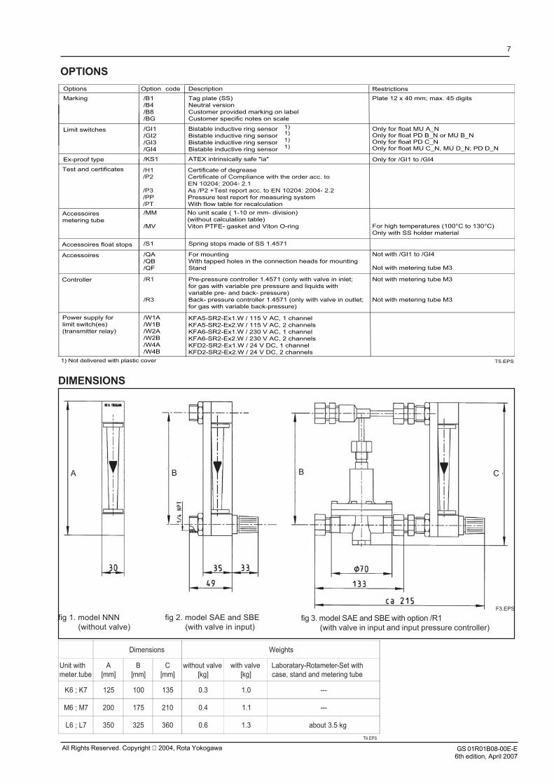
DIMENSIONS
F3.EPS
CBBA
fig 1. model NNN (without valve)
fig 2. model SAE and SBE (with valve in input)
fig 3. model SAE and SBE with option /R1 (with valve in input and input pressure controller)
Dimensions Weights
Unit withmeter.tube
A[mm]
B[mm]
C[mm]
without valve[kg]
with valve[kg]
Laboratary-Rotameter-Set withcase, stand and metering tube
K6 ; K7 125 100 135 0.3 1.0 ---
M6 ; M7 200 175 210 0.4 1.1 ---
L6 ; L7 350 325 360 0.6 1.3 about 3.5 kg
T6.EPS
GS 01R01B08-00E-E6th edition, April 2007
All Rights Reserved. Copyright 2004, Rota Yokogawa

8
GS 01R01B08-00E-E6th edition, April 2007
All Rights Reserved. Copyright 2004, Rota Yokogawa