Microcomputer Protection Relays and Monitoring Device for Line Protection
description

ABB ATCF-PT
General Line ProtectionGeneral Line Protection
1
1. Distance relays - basics2. Operating characteristics3. Effect of parallel line4. Phase selection5. Power swing blocking6. Communication scheme7. Switch on to fault8. Weak end infeed9. Supervision fuse failure10. System supervision.11. Fault locator12. Stub protection13. Earth fault protection14. Auto reclosing systems
List of Topics

ABB ATCF-PT
General Line ProtectionGeneral Line Protection
2
1-Distance relay basics
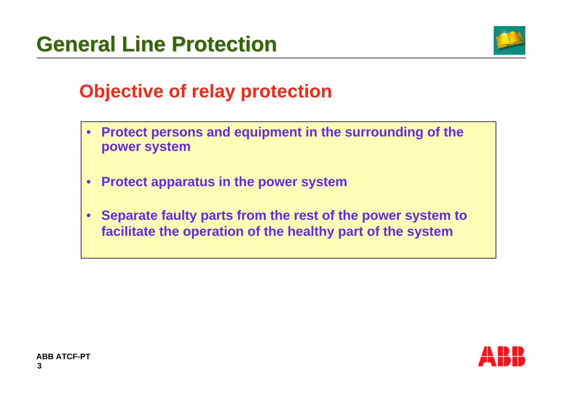
ABB ATCF-PT
General Line ProtectionGeneral Line Protection
3
Objective of relay protection
• Protect persons and equipment in the surrounding of thepower system
• Protect apparatus in the power system
• Separate faulty parts from the rest of the power system tofacilitate the operation of the healthy part of the system

ABB ATCF-PT
General Line ProtectionGeneral Line Protection
4
Electrical faults in the power system
• Transmission lines 85%• Busbar 12%• Transformer/ Generator 3%
Total 100 %

ABB ATCF-PT
General Line ProtectionGeneral Line Protection
5
Fault statistics
• Single phase to earth 80%• Two phases to earth 10%• Phase to phase faults 5%• Three phase faults 5%
The probability of line faults caused bylightnings are 0,2-3 faults/ 100 km and year

ABB ATCF-PT
General Line ProtectionGeneral Line Protection
6
Fault types
• Transient faults– are common on transmission lines, approximately 80-85%– lightnings are the most common reason– can also be caused by birds, falling trees,Forest growth,
swinging lines, High velocity winds etc.– will disappear after a short dead interval
• Persistent faults
– can be caused by a broken conductor fallen down– can be a tree falling on a line– must be located and repaired before normal service

ABB ATCF-PT
General Line ProtectionGeneral Line Protection
7
Fault types on double circuit lines
• Simultaneous and Interline faults– On parallel line applications a problem can
occur with simultaneous faults.– A full scheme relay is superior when the
protection is measuring two different faulttypes at the same time.
L1
L3
L3
L1
L2
L2
~~ Z<
L2-N
L1-N

ABB ATCF-PT
General Line ProtectionGeneral Line Protection
8
Fault resistance
• multi-phase faults consist only of arc resistance
• earth faults consist of arc and tower footing resistance
L1
L3
L3
L1
L2
L2
Footing resistance
Rarc =28707 x L
1.4I
Warrington´s formula
L= length of arc in meters
I= the actual fault current in A

ABB ATCF-PT
General Line ProtectionGeneral Line Protection
9
Fault types
• Mid-span faults– the fault resistance is out of control– can be caused by growing trees, bushfire or objects
touching a conductor– this type of high resistive faults can not be detected by
impedance protection

ABB ATCF-PT
General Line ProtectionGeneral Line Protection
10
MAIN REQUIREMENTS ON LINE PROTECTION ARE:
• SPEED• SENSITIVITY• SELECTIVITY• DEPENDABILITY• SECURITY• RELIABILITY• MTBF
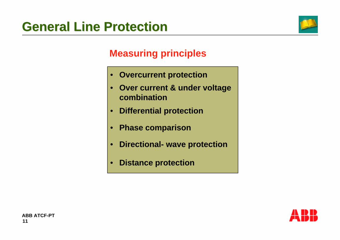
ABB ATCF-PT
General Line ProtectionGeneral Line Protection
11
Measuring principles
• Overcurrent protection
• Over current & under voltagecombination
• Differential protection
• Phase comparison
• Directional- wave protection
• Distance protection

ABB ATCF-PT
General Line ProtectionGeneral Line Protection
12
The principle of distance protection
Z<
ZK=Uk/ Ik
Uk=0Uk
Zk IkA B
metallic fault

ABB ATCF-PT
General Line ProtectionGeneral Line Protection
13
The principle of distance protection
• Power lines have impedances of size 0,3- 0,4 ohm/ km and normalangles of 80 - 85 degrees in a 50Hz systems.
• The line impedance must be converted to secondary values with theformula:
A
Z<
B
Z<
ZL=R+jX
Zsec=VTsec
VTprim CTsec
CTprimZprimx x

ABB ATCF-PT
General Line ProtectionGeneral Line Protection
14
The principle of distance protectiont
l
A
Z<
B
Z< Z<
C
Z< t
t1
t2t3
lt1t2t3
f1 f2 f3

ABB ATCF-PT
General Line ProtectionGeneral Line Protection
15
Measuring loop for earth faults
• The distance protection relays are always setbased on the phase impedance to the fault
Zs RL XL
The measured Impedance is a function ofpositive and zero sequence impedance
RN XN
IL1UL1
IN

ABB ATCF-PT
General Line ProtectionGeneral Line Protection
16
Measuring loop for two- phase faults
• The distance protection relays are always setbased on the phase impedance to the fault
Zs RL XL
UL1-L2IL1
IL2
The measured impedance is equal to thepositive sequence impedance up to the faultlocation

ABB ATCF-PT
General Line ProtectionGeneral Line Protection
17
Measuring loop for three- phase faults
• The distance protection relays are always setbased on the phase impedance to the fault
The measured impedance is equal to thepositive sequence impedance up to the faultlocation
Zs RL XL
UL1IL1IL2
IL3UL2
UL3
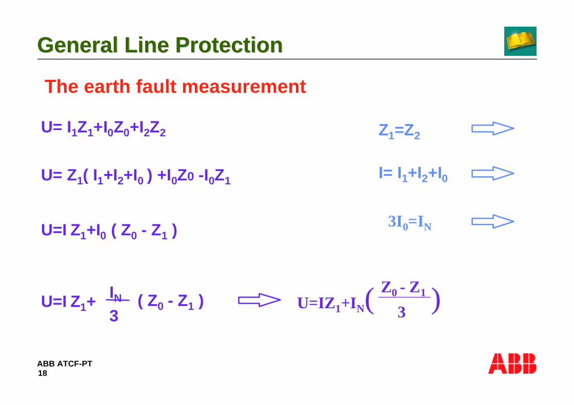
ABB ATCF-PT
General Line ProtectionGeneral Line Protection
18
The earth fault measurement
U= I1Z1+I0Z0+I2Z2 Z1=Z2
U= Z1( I1+I2+I0 ) +I0Z0 -I0Z1 I= I1+I2+I0
U=I Z1+I0 ( Z0 - Z1 )3I0=IN
U=IZ1+IN(Z0 - Z1
3 )U=I Z1+IN3
( Z0 - Z1 )

ABB ATCF-PT
General Line ProtectionGeneral Line Protection
19
The earth fault measurement
• The current used is thus the phase current plus the residualcurrent times a factor KN = (Z0-Z1) / 3Z1, the zero sequencecompensation factor.
• The factor KN is a transmission line constant and Z0/ Z1 ispresumed to be identical throughout the whole line length.
• (1+KN) Z1 gives the total loop impedance for the earth faultloop for single end infeed.

ABB ATCF-PT
General Line ProtectionGeneral Line Protection
20
Double end infeed
I1
I1 I2
UF RF
UF = RF ( I1 + I2 )
RF ( I1 + I2 )RF1=
U1 U2
I Load

ABB ATCF-PT
General Line ProtectionGeneral Line Protection
21
Measuring error at high resistive earth fault on aline with double end infeed
X
ZL
Rf Load export
Rf Load import
R

ABB ATCF-PT
General Line ProtectionGeneral Line Protection
22
Remote faults
– Due to current contribution If2 and If3 in substation B, thedistance protection in station A will measure a higherimpedance than the "true" impedance to the fault.
– The relay will thus underreach and this means in practice itcan be diffcult to get a remote back-up.
Um= If1 x ZL+ (If1+If2+If3) x ZF
Z<
If1 If2
If3 If=If1+If2+If3
ZL
ZF
A B
Um

ABB ATCF-PT
General Line ProtectionGeneral Line Protection
23
Directional measurement
• When a fault occurs close to the relay location thevoltage can drop to a value where the directionalmeasurement can not be performed.
– Modern distance protection relays will instead use thehealthy voltage e.g. for L1- fault the voltage UL2-L3,shifted 90 degrees compared to UL1. This crosspolarisation is used in different proportions betweenhealthy and faulty phases in different products.
– At three- phase fault close to the station all phasevoltages are low and cross polarisation is not of any use.Instead a memory voltage is used to secure correctmeasurement.

ABB ATCF-PT
General Line ProtectionGeneral Line Protection
24
Design of distance protection
• Switched scheme– consists of a start relay to select (switch) the measuring
loop to the single measuring relay
• Full scheme– has a measuring element for each measuring loop and
for each zone
~~ Z<
L2-N
L1-N

ABB ATCF-PT
General Line ProtectionGeneral Line Protection
25
2- Operating characteristic

ABB ATCF-PT
General Line ProtectionGeneral Line Protection
26
SHOULD COVER AS MUCH AS POSSIBLE OF PROTECTED CIRCUIT AND OF ADDITIONAL RESISTANCE.
• IN CASE OF Ph TO GROUND FAULT FOLLOWED BY RECLOSURE TO TRIPPING IN UNFAULTED PHASES.
• FAST OPERATION
• DIRECTIONAL DISCRIMINATION.
THE FIRST ZONE CHARACTERISTIC

ABB ATCF-PT
General Line ProtectionGeneral Line Protection
27
EXTENSION UPWARDS AND TO THE RIGHT SHOULD ENCLOSE AS MUCH OF LINE IMPEDANCE AND ADDITIONAL RESISTANCE WITHOUT OVERREACH.
• REACH IN RESISTIVE DIRECTION SHOULD BE LARGE ENOUGH TO COVER LARGE RESISTANCE AND TO GET GOOD DYNAMIC PERFORMANCE BUT LIMITED TO AVOID UNWANTED TRIPPING IN CASE OF POWER SWINGS , OVERREACH IN ADDITIONAL RESISTANCE IS SEEN WITH LARGE CAPACITIVE REACTANCE , SHORT TIME OVERLOADING.
THE FIRST ZONE CHARACTERISTIC(Contd..)

ABB ATCF-PT
General Line ProtectionGeneral Line Protection
28
EXTENSION UPWARDS IS DECIDED BY IMPEDANCE OF PROTECTED LINE AND SETTING OF I ZONE OF ADJACENT LINES.
• IN MOST CASES R-AXIS REACH OF ZONE - II SAME AS ZONE -I IS SATISFACTORY. IF ADDITIONAL RESISTANCES ARE EXPECTED WHICH ZONE - I IS NOT ABLE TO COVER THEN DIFFERENT SETTING FOR ZONE - II IS ADVANTAGEOUS.
THE SECOND ZONE CHARACTERISTIC
ABB ATCF-PT
General Line ProtectionGeneral Line Protection
29
THIS IS THE WIDEST OF ZONES IN WHICH TRIPPING CAN OCCURAFTER LONGEST TIME DELAY.
• IS REQUIRED TO GIVE REMOTE BACKUP THOUGH IN MANY CASES IT IS IMPOSSIBLE TO GET COMPEREHENSIVE REMOTE BACK UP.
THE THIRD ZONE CHARACTERISTIC

ABB ATCF-PT
General Line ProtectionGeneral Line Protection
30
DISTANCE PROTECTION ON SHORT LINES.jX
RF
XF R
• Low measured reactance
• Ratio between fault resistance and resistance is high.
• Distance protection with mho characteristic can not see an average fault resistance.

ABB ATCF-PT
General Line ProtectionGeneral Line Protection
31
DISTANCE PROTECTION ON SHORT LINES
jX
RF
XF R
• Low measured reactance
• Ratio between fault resistance and reactance is high.
• Distance protection with mho characteristic can not see average fault resistance.
• Cross polarization has no significant effect.

ABB ATCF-PT
General Line ProtectionGeneral Line Protection
32
jX
RF
XFR
DISTANCE PROTECTION ON SHORT LINES
• Quadrilateral characteristic improves sensitivity for higher RF/XF ratio.
• It still has some limitations. -The value of set RF/ XF ratio is is limited by 5 - Remote infeed increases the apparent value of fault resistance. - Requirements on current instrument transformers are stringent.

ABB ATCF-PT
General Line ProtectionGeneral Line Protection
33
DISTANCE PROTECTION ON SHORT LINES.
jX
R
RF
XF
• Teleprotection schemes improve the total system behavior.
• Overreaching permissive schemes increase the sensitivity.
• Weak infeed logic for very high fault resistance.
• Requirements on CT’s are decreased.
• Independent underreaching zone 1 is sometimes an additional advantage.

ABB ATCF-PT
General Line ProtectionGeneral Line Protection
34
jX
R
DISTANCE PROTECTION ON LONG LINES
• Load impedance limits the reach in resistive direction.
• High value of RF / XF ratio is generally not necessary.

ABB ATCF-PT
General Line ProtectionGeneral Line Protection
35
DISTANCE PROTECTION ON LONG LINES
R
• Load impedance limits the reach in resistive direction.
• High relay of RF/ XF ratio is generally not necessary
• Circular (mho) characteristic - has no strictly defined reach in resistive direction. - needs limitation in resistive direction (blinder)• Influences of heavy load current at phase to earth faults.
• Sensitivity for low currents.

ABB ATCF-PT
General Line ProtectionGeneral Line Protection
36
• AT THE ORIGIN DIRECTIONAL DISCRIMINATION REQUIRED BY LINE PASSING THROUGH 2nd QUADRANT , 4th QUADRANT AND ORIGIN.
• THE DIRECTIONAL MEASUREMENT IS BASED ON THE USE OF + VE SEQUENCE VOLTAGE FOR THE RESPECTIVE FAULT LOOP.
•VOLTAGE USED FOR RPH ELEMENT IS 0.8 U1R + 0.2 U 1RM WHERE U1RM IS MEMORY VOLTAGE (+VE SEQUENCE)
THIS WILL ENSURE CORRECT DIRECTIONAL DISCREMINATION.EXTENSION IN 2nd AND 4th LIMITED TO AVOID OPERATION OF UNFAULTED PHASE AN ALSO DURING SWINGS YET GIVE GOOD DYNAMIC PERFORMANCE.

ABB ATCF-PT
General Line ProtectionGeneral Line Protection
37
LOAD CURRENT INFLUENCES THE IMPEDANCE MEASUREMENT.Li
ne im
peda
nce

ABB ATCF-PT
General Line ProtectionGeneral Line Protection
38
Characteristic with out load compensation
The same fault positionEqual fault resistance
LOAD CURRENT INFLUENCES THE IMPEDANCE MEASUREMENT.Li
ne im
peda
nce

ABB ATCF-PT
General Line ProtectionGeneral Line Protection
39
∼ ∼ILOAD
EA
EB
A B
RF
IFA IFB
ZL
EXPORTING ENDOVERREACHING
IMPORTING END OVERREACHING
ZM = ZL + RF ( 1 + IFB
I FA)
Note : Currents and voltages are phasors

ABB ATCF-PT
General Line ProtectionGeneral Line Protection
40
Characteristic with out load compensation
The same fault positionEqual fault resistance
LOAD CURRENT INFLUENCES THE IMPEDANCE MEASUREMENT.
Load compensated characteristic
Line
Impe
danc
e

ABB ATCF-PT
General Line ProtectionGeneral Line Protection
41
IT IS NOT WHAT MANY HOPE IT IS
•RCALC is an interactive PC based program, which helps the users in determination of optimum settings of distance protection.
•Its operation is based on real algorithms used in the distance protection.
•It includes measuring characteristics for : -RAZOA and RAZFE -REZ 1 and REL 100 -distance protection in REL 5XXRC
ALC

ABB ATCF-PT
General Line ProtectionGeneral Line Protection
42
IT IS NOT WHAT MANY HOPE IT IS
•It presents the operation areas of distance protection zones in impedance ( R- X ) plane• Simulates two machine system : -single line. -double circuit line with zero sequence mutual coupling. -remaining network (line) between two busbars. -load conditions -changing fault resistance.RC
ALC

ABB ATCF-PT
General Line ProtectionGeneral Line Protection
43
3- Effect of parallel line

ABB ATCF-PT
General Line ProtectionGeneral Line Protection
44
Zero- sequence mutual coupling on parallel lines
ZA< overreaching ZB< underreaching
ZL
~ ZOMZL
~
ZA< ZB<
~
~

ABB ATCF-PT
General Line ProtectionGeneral Line Protection
45
Zero- sequence mutual coupling on parallel lines
• In double circuit lines and parallel lines the zero sequence couplingwill result in measuring errors, specially at ground faults.
• The mutual impedance will either cause an extension or reduction ofthe set reach on the relay.
• Maximum overreaching will occur when the parallel line is out ofservice and grounded at both ends.
• The overreaching caused by the grounded parallel line can beavoided at the setting of the relay, by the KN factor.

ABB ATCF-PT
General Line ProtectionGeneral Line Protection
46
EFFECT OF MUTUAL COUPLING ON DISTANCERELAYS
∼ ∆∆ ∼
PARALLEL LINE EARTH CURRENT = IEP = 3IOP
INDUCED VOLTAGE IN THE FAULT LOOP = IEP • ZOM / 3DISTANCE RELAY PH- EARTH UNIT MEASURES
Z = VPH- E / ( I PH + KO IE ) WHERE KO = ZOL - ZL / 3ZL
= ZL • IPH + ( ZOL - ZL ) IE / 3ZL + IEP • ZOM / 3ZL IPH + KO IE
= ZL [ 1 + KOM • IEP / IPH + KO IE ] WHERE KOM = ZOM / 3ZL
ZOM
ERROR
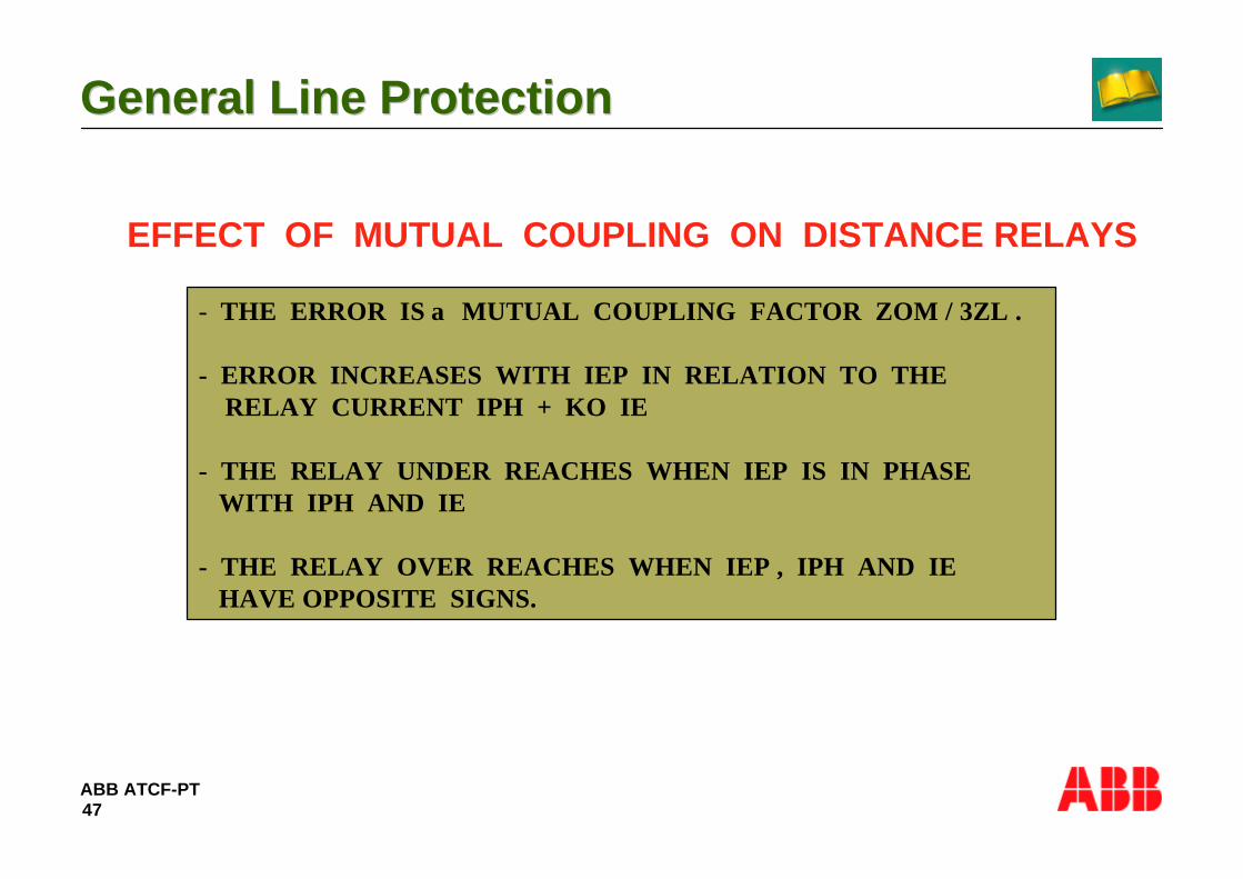
ABB ATCF-PT
General Line ProtectionGeneral Line Protection
47
EFFECT OF MUTUAL COUPLING ON DISTANCE RELAYS
- THE ERROR IS α MUTUAL COUPLING FACTOR ZOM / 3ZL .
- ERROR INCREASES WITH IEP IN RELATION TO THE RELAY CURRENT IPH + KO IE
- THE RELAY UNDER REACHES WHEN IEP IS IN PHASE WITH IPH AND IE
- THE RELAY OVER REACHES WHEN IEP , IPH AND IE HAVE OPPOSITE SIGNS.

ABB ATCF-PT
General Line ProtectionGeneral Line Protection
48
EFFECT OF MUTUAL COUPLING ON DISTANCE RELAYS
∆ ∆ ∼ ∼
∆Z = - ZLKOM • ZOM / ZOL
1 + KO •
= - 0.23 ZL

ABB ATCF-PT
General Line ProtectionGeneral Line Protection
49
EFFECT OF MUTUAL COUPLING ON DISTANCE RELAYS.
∆Z =
∼ ∆
DKOM
1 + KO• ZL
= 0.38 ZLKO =
ZOL - ZL
3 ZL= 0.864
KOM = ZOM / 3ZL = 0.716
R1 + j X1 = 0.0289 + j 0.307 Ω / KM
RO + j X0 = 0.276 + j 1.0715 Ω / KM
RMO1 + j XMO = 0.228 + j 0.622 Ω / KM
∴ ZL = 0.308 Ω / KM
ZOL = 1.106 Ω /KM
ZOM = 0.662 Ω/ KM
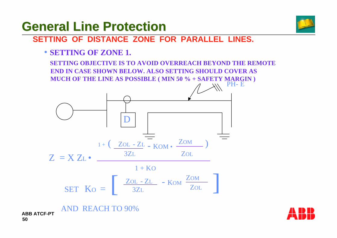
ABB ATCF-PT
General Line ProtectionGeneral Line Protection
50
SETTING OF DISTANCE ZONE FOR PARALLEL LINES.
• SETTING OF ZONE 1. SETTING OBJECTIVE IS TO AVOID OVERREACH BEYOND THE REMOTE END IN CASE SHOWN BELOW. ALSO SETTING SHOULD COVER AS MUCH OF THE LINE AS POSSIBLE ( MIN 50 % + SAFETY MARGIN )
∼D
PH- E
1 + ( ZOL - ZL
3ZL - KOM •
ZOM
ZOL
)
1 + KOZ = X ZL •
∴ SET KO = [ ZOL - ZL 3ZL
- KOM ZOM
ZOL ]AND REACH TO 90%

ABB ATCF-PT
General Line ProtectionGeneral Line Protection
51
WITH THE ABOVE FOR OTHER CASES VIZ PARALLEL LINES SWITCHED OFF AND NOT EARTHED & BOTH LINES IN SERVICE THE REACH WILL REDUCE AS GIVEN BELOW.
- PARALLEL LINE SWITCHED OFF AND NOT EARTHED - 69%- BOTH LINES IN SERVICE - 60%

ABB ATCF-PT
General Line ProtectionGeneral Line Protection
52
SETTING OF DISTANCE ZONES FOR PARALLEL LINES
• SETTING OF ZONE 2
SETTING OBJECTIVE IS RELAY MUST SAFELY COVER 100 % OF THE LINE WITH SAFTEY MARGIN OF 20 % FOR THE MOST UNFAVOURABLE CONDITION.
∼
PH - E
Z = ZL 1 + (ZOL - ZL ) / 3ZL + KOM
1 + KO[ ]∴ SET K0 =
ZOL - ZL
3 ZL+ KOM AND REACH TO 120 %

ABB ATCF-PT
General Line ProtectionGeneral Line Protection
53
FOR OTHER CASES VIZ PARALLEL LINE SWITCHED OFF AND EARTHED AT BOTH LINE ENDS IT MUST BE ENSURED THATTHIS DOES NOT OVERLAP WITH THE ZONE 2 OF THE FOLLOWING LINE.
Z Z
ZL 0. 44
THIS MEANS IN THE CASE OF 2nd ZONE SET TO 120 % OFZL
WOULD HAVE A REACH OF 173 % OF ZL.
IN NORMAL PRACTICE THIS PROVIDES NO PROBLEMS ASOVERRECH IN TO FOLLOWING LINE IS REDUCED BYINTERMEDIATE INFEEDS AT REMOTE STATION.

ABB ATCF-PT
General Line ProtectionGeneral Line Protection
54
THE INFLUENCE OF ZERO SEQUENCE MUTUAL COUPLING CAN BE COMPENSATED IN NUMERICAL RELAYS IN TWO DIFFERENT WAYS
ALT 1 -BY USING POSSIBILITY OF DIFFERENT VALUES OF EARTH RETURN COMPENSATING FACTOR K FOR DIFFERENT ZONESWITHIN THE SAME GROUP OF SETTING PARAMETERS.
ALT 2 -BY USING DIFFERENT GROUPS OF SETTING PARAMETERSFOR DIFFERENT OPERATING CONDITIONS OF PROTECTEDDOUBLE CIRCUIT LINE.
∼

ABB ATCF-PT
General Line ProtectionGeneral Line Protection
55
ALTERNATIVE 1
KN1 = [ZOL - ZL
3ZL- KOM
ZOM
ZOL ]= [
ZOL - ZL
3ZL+ KOM
]
= [ZOL - ZL
3ZL ]
KN2
KN3
WHERE KOM = ZOM / 3ZL

ABB ATCF-PT
General Line ProtectionGeneral Line Protection
56
ALTERNATIVE 2
= [Z O L - Z L
3 Z L- K O M
Z O M
Z O L ]CASE 1 - PARALLEL LINE SWITCHED OFF WITH BOTH ENDS EARTHED.
KN1
KN2 , KN3 IDENTICAL TO ALT 1
CASE 2 - DOUBLE CIRCUIT PARALLEL LINE IN OPERATION.
= [ZOL - ZL
3ZL+ KOM
] KN2 , KN3 IDENTICAL TO ALT 1
KN1

ABB ATCF-PT
General Line ProtectionGeneral Line Protection
57
4-Phase selection

ABB ATCF-PT
General Line ProtectionGeneral Line Protection
58
AN INDEPENDENT PHASE SELECTION FUNCTION OPERATESAS A COMPLEMENT TO THE IMPEDANCE MEASURIING ELEMENTSO AS TO SECURE CORRECT PHASE SELECTION IN CASEOF SINGLE PH TO EARTH FAULTS ON HEAVILY LOADED LONGTRANSMISSION LINES AND ALSO MULTI CIRCUIT.
IT IS NOT NECESSARY TO SET THESE TO COVER ALLZONES. IT IS ENOUGH IF IT COVERS FIRST OVERREACHING ZONE ( ZONE 2 ) MEASURING ELEMENT FOR DIFFERENTFAULT LOOPS BUT FOR PHASE INDICATIONS.
PHASE SELECTION.

ABB ATCF-PT
General Line ProtectionGeneral Line Protection
59
PHASE SELECTION • I PH FAULTS.
Characteristic of phase selector for single-phase faults.
jX
XNPh
RNPhR
RN2
2 . ( 1 + Kn )
UR
IR< R N4 + j x N4
Us Is
R N4 + j x N4<
UT
IT R N4 + j x N4<
ALSO
3Io > 0.1 In
&3Io > 0.2 IpHMAX

ABB ATCF-PT
General Line ProtectionGeneral Line Protection
60
PHASE SELECTION • 2 PH FAULTS.
Characteristic of phase selectors for two-phase faults.
jX
R
XPh
RPh
2. X2
2.R2 70•
α
∂
UR - UTIR
< R4 + j X4
R4 + j x4
R4 + j x4
Us - UR <IS
UT - UR
IT<
ALSO
3Io < 0.2 IN & 3Io < 0.4IpHMAX

ABB ATCF-PT
General Line ProtectionGeneral Line Protection
61
Characteristic of phase selectors at three phase faults.
jX
R
100 •
RPh 2/√3
2.X2
2. R2
XPh .2/
α
δ
jX’
R’PHASE SELECTION
• 3 PH FAULTS.
THIS IS SIMILAR TOPH - PH FAULTS WITHFOLLOWING DEVIATIONS.
- ROTATED ANTICLOCKWISE BY 30 DEGREES.- REACH 2/ √ 3 TIMES THAT OF FOR PH - PH FAULTS.

ABB ATCF-PT
General Line ProtectionGeneral Line Protection
62
5- Power swing blocking

ABB ATCF-PT
General Line ProtectionGeneral Line Protection
63
Power Swing Blocking (PSB) function
• A power swing can be started by sudden load change due toa fault somewhere in the network.
• Close to the centre of the power swing, low voltage and thuslow impedance will occur.
• A distance protection relay must then be blocked during thepower swing.
• This can be done by mesuring the transit time of theimpedance locus passing two dedicated impedance zones.
• Normally the time used is 35-40 ms.

ABB ATCF-PT
General Line ProtectionGeneral Line Protection
64
POWER SWING BLOCKING FUCTION
•WHEN POWER SWING DETECTION UNIT OPERATES ANY IMPEDENCEZONE CAN BE SELECTED TO BE BLOCKED OR NOT AS REQUIRED.
•OPERATION OF POWER SWING DETECTION UNIT IS INHIBITED WHEN ZERO SEQUENCE CURRENT IS DETECTED. THIS FEATURE ISINCLUDED TO ENSURE TRIPPING OF HIGH RESISTANCE EARTH FAULTSWHERE FAULTS WHERE FAULT RESISTANCE CAN DECREASE SLOWELY.
•THE RESIDUAL CURRENT INHIBIT CONDITION ENSURE PSD WILL NOT BLOCK DUE TO UNBALANCED LOAD OR RESIDUAL CURRENT EXPERIENCED WITH UNTRANSPOSEDTRANSMISSION LINES.

ABB ATCF-PT
General Line ProtectionGeneral Line Protection
65
Power Swing Blocking function
∆t
∆t = 40 ms
X
R
Power swing locus
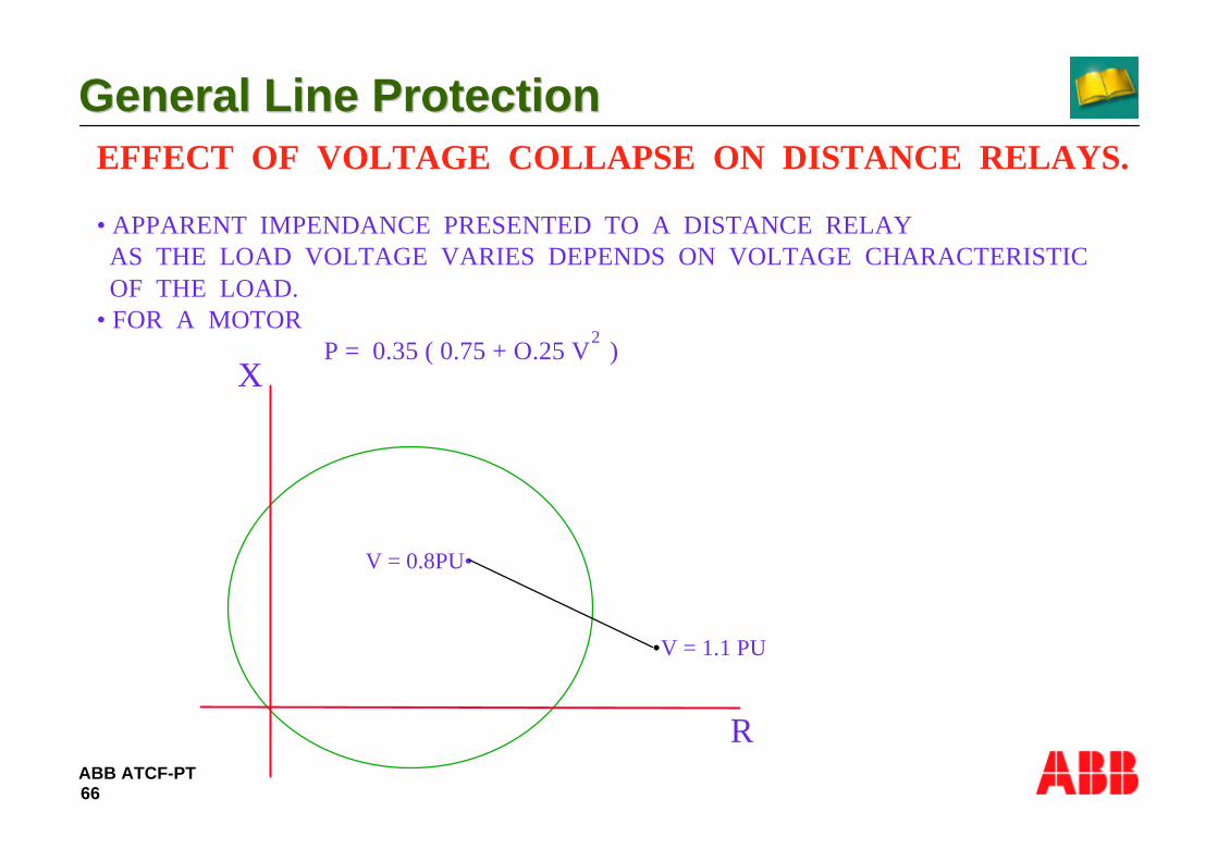
ABB ATCF-PT
General Line ProtectionGeneral Line Protection
66
EFFECT OF VOLTAGE COLLAPSE ON DISTANCE RELAYS.
• APPARENT IMPENDANCE PRESENTED TO A DISTANCE RELAY AS THE LOAD VOLTAGE VARIES DEPENDS ON VOLTAGE CHARACTERISTIC OF THE LOAD.• FOR A MOTOR P = 0.35 ( 0.75 + O.25 V )
2
X
R
V = 0.8PU•
•V = 1.1 PU

ABB ATCF-PT
General Line ProtectionGeneral Line Protection
67
• SIMPOW IS A COMPUTER PROGRAMME DEVELOPED BY ABB POWER SYSTEM AB
• FOLLOWING STUDIES CAN BE DONE BY SIMPOW
- STEADY STATE (POWER FLOW , FAULT CURRENT , HARMONICS).
- ELECTRO MECHANICAL TRANSIENTS ( LONG TERM DYNAMICS , SHORT TERM DYNAMICS , MACHINE TRANSIENTS).
- ELECTRO MAGNETIC TRANSIENTS (SATURATION AND RESONANCE SWITCHING TRANSIENTS , LIGHTNING TRANSIENTS).
- ANALYSIS (FREQUENCY SCANNING , EIGEN VALUES AND VECTORS, MODEL ANALYSIS).
SIMPOW ( SIMULATION OF POWERSYSTEMS )

ABB ATCF-PT
General Line ProtectionGeneral Line Protection
68
6- Communication scheme

ABB ATCF-PT
General Line ProtectionGeneral Line Protection
69
COMMUNICATION EQUIPMENT
∼ ∼× × × ×××A B
IN THE ABSENCE OF COMMUNICATION LINK
-THE OPERATION ZONE OF END ZONE FAULT IS LONGER.-AUTO RECLOSING IS NOT POSSIBLE.

ABB ATCF-PT
General Line ProtectionGeneral Line Protection
70
Communication equipment• Power line carrier (PLC) equipment is based on a capacitive
connection of signals with frequency in the range 50- 500 kHz on thepower line.
• Radio link is a good and reliable communication equiment, but israrely used due to the high cost.
• Optical fibres have the advantage to be insensitive to noise and cantransmit a huge amount of information.

ABB ATCF-PT
General Line ProtectionGeneral Line Protection
71
RELAY SETTING AND THE WAY SIGNALS ARE USED IS GIVENBELOW.
FIRST ZONE REACH• UNDER REACHING (0.8 TO 0.9 Z AB )• OVER REACHING ( 1.2 Z AB)
USE OF RECIVED SIGNAL• OPERATION OF CB IF LOCAL RELAY HAS PICKED UP• AS INFORMATION REGARDING DIRECTION OF FAULT - FOR COMPARISON WITH LOCAL END - TO EXTEND ZONE I REACH - TO BLOCK RELAY OPERATION
COMMUNICATION EQUIPMENT

ABB ATCF-PT
General Line ProtectionGeneral Line Protection
72
Permissive communication schemes– Communication signal carrier send (CS) is sent to remote end
when the fault is detected in forward direction. Tripping is achievedwhen the commmunication signal carrier receive (CR) is receivedand the local relay has detected a forward fault.
– In a permissive underreaching scheme the communication signal issent from a zone that underreaches the remote end.
– In a permissive overreaching scheme the communication signal issent from a zone that overreaches the remote end.
A
Z< Z<
B
Carrier send CS = Z< forward, under or overreach
Trip = ZM1 + ZM2 (t2 + CR) + ZM3 x t3

ABB ATCF-PT
General Line ProtectionGeneral Line Protection
73
PERMISSIVE OVERREACHING SCHEMES ARE ADOPTED FOR SHORT LINES ( ALSO CALLED DIRECTIONAL COMPARISON SCHEMES)
ADVANTAGES ARE • BETTER PERFORMANCE FOR HIGH RESISTANCE FAULTS. • SUPERIOR TO PILOT WIRE AS DIGITAL DECISIONS ARE EXCHANGED AND NOT ANALOGUE • SUPERIOR TO PHASE COMPARISON WHICH REQUIRES FAITHFUL TRANSMISSION OF PHASE INFORMATION.
PERMISSIVE COMMUNICATION SCHEMES

ABB ATCF-PT
General Line ProtectionGeneral Line Protection
74
Blocking communication schemes
– Communication signal (CS) is sent to remote end when thefault is detected in the reverse direction. Tripping is achievedwhen this blocking signal is not received within a time T0 (20-40 ms) and the local relay has detected a fault in the forwarddirection.
A B
Z< Z<
Carrier send CS = Z< reverse zone
Trip = ZM1 + ZM2 (t2 + CR x T0) + ZM3 x t3
ABB ATCF-PT
General Line ProtectionGeneral Line Protection
75
BLOCKING COMMUNICATION SCHEMES
BLOCKING SCHEMES ARE USED WHEN COMMUNICATION SIGNALSSHALL NOT BE TRANSMITTED OVER FAULTY LINE FOR RELIABILITYREASONS Ex : BOOSTING OF SIGNAL NOT PERMITTED.

ABB ATCF-PT
General Line ProtectionGeneral Line Protection
76
7- Current reversal logic

ABB ATCF-PT
General Line ProtectionGeneral Line Protection
77
Current reversal logic
~~
~~A:1 B:1
A:2 B:2
A:1 B:1
A:2 B:2
Permissive overreaching schemescan trip healthy line without C.R.L
1 Fault occurs on line 1
Fault detection by protection A:1 B:1 and A:2
2 Relay B:1 trips CB and sends carrier to A:1
Relay A:2 sees fault in forward direction andsends carrier to B:2
3 Fault cleared at B:1, current direction changedon line 2
4 Carrier from A:2 and forward looking measuringelement in relay A:2 does not reset before relayB:2 detects the fault in forward direction andtrips, also relay A:1 will trip when receiving carrierfrom B:1
C.R.L allows slowly resettingcommunication equipment without riskof tripping the healthy line.

ABB ATCF-PT
General Line ProtectionGeneral Line Protection
78
8- Switch on to fault

ABB ATCF-PT
General Line ProtectionGeneral Line Protection
79
Switch On To Fault (SOTF)
• When energizing a power line onto a forgotten earthing nomeasuring voltage will be available and the directional measuringcan thus not operate correctly.
– A special SOTF function is thus provided. Different principlescan be used, from one phase current to undirectionalimpedance measuring.
Z<
U=0 V
SOTF conditon can either betaken from the manual closingsignal activating the (BC) inputor it can be detected internaly bya logic.

ABB ATCF-PT
General Line ProtectionGeneral Line Protection
80
9- Week end infeed

ABB ATCF-PT
General Line ProtectionGeneral Line Protection
81
Weak end infeed
Weak end infeed is a condition which can occur on a transmissionline, either when the circuit breaker is open, so there is no currentinfeed from that line end, or when the current infeed is low due toweak generation behind the protection.
CS = ZM2
TRIP = ZM1 + ZM2(CR + t2)CS (echo)=CR x low voltage x no start forward or reverse
lt1
t2t3
Z< Z<CS
CS (echo)CR
CR

ABB ATCF-PT
General Line ProtectionGeneral Line Protection
82
WEAK END INFEED
• IN PERMISSIVE OVER REACH SCHEMES BOTH CBS MAY FAIL TO TRIP INSTANEOUSLY DUE TO NO CARRIER SEND SIGNAL AND NO RELAY OPERATION IN WEAK END.
• IN PERMISSIVE UNDERREACH SCHEMES FAST FAULT CLEARENCE OF WHOLE LINE SECTION WILL NOT BE THERE BECAUSE NO SIGNALS WILL BE SENT FROM THE WEAK END.
• IN BLOCKING SCHEME OR PERMISSIVE UNDERREACH SCHEME THE LOW INFEED END WILL FAIL TO TRIP INSTANTANEOUSLY.
DUE TO WEAK END INFEED FOLLOWING WILL HAPPEN.
ABB ATCF-PT
General Line ProtectionGeneral Line Protection
83
WEAK END INFEED.
THE LOGIC DESCRIBED FOR PERMISSIVE OVERREACH SCHEME CANBE USED IN TWO MODES. -ECHO FOR COMMUNICATION SIGNAL ONLY. -ECHO OF COMMUNICATION SIGNAL AND TRIP OF LOCAL CB.
IN CASE OF PERMISSIVE UNDERREACH SCHEME THE LAST 10-20 %TOWARDS WEAK END WILL BE CLEARED IN ZONE II TIME .IF THIS IS NOT ACCEPTABLE OVERREACH SCHEME SHOULD BE USED.
IN BLOCKING SCHEME WEAK END CB CANNOT BE TRIPPED .IN SUCH CASE DIRECT TRIPPING FROM ZONE I AND ACCLERATEDZONE MUST BE USED.
ABB ATCF-PT
General Line ProtectionGeneral Line Protection
84
10- Supervision of fuse failure

ABB ATCF-PT
General Line ProtectionGeneral Line Protection
85
THIS FUCTION IS BASED ON CONDITION
3UO > 20 % OF Un / √ 3 AND 3IO < 20 % OF In
IT CAN BE SELECTED TO BLOCK PROTECTION AND GIVE ALARMOR JUST TO GIVE ALARM.
FUSE FAIL SUPERVISION IS BLOCKED FOR 200ms FOLLOWING LINE ENERGISATION IN ORDER NOT TO OPERATE FOR UNEQUALPOLE CLOSING AND ALSO DURING AUTORECLOSING.
MCB CAN ALSO BE USED.
FUSE FAIL SUPERVISION

ABB ATCF-PT
General Line ProtectionGeneral Line Protection
86
11- System supervision
ABB ATCF-PT
General Line ProtectionGeneral Line Protection
87
SYSTEM SUPERVISION.
• OVER LOAD SUPERVISION GIVES ALARM IF CURRENT EXCEEDS FOR10 SECS.
• UNSYMMETRICAL LOAD CONDITION CHECK GIVES ALARM WHEN ANY PHCURRENT IS LOWER THEN 80% OF LARGEST PH CURRENT. ALSOLARGEST PH CURRENT MUST BE > 15% OF NOMINAL CURRENT.
• LOSS OF VOLTAGE SUPERVISION CAN TRIP OR GIVE ALARM WHEN ALL3 PH VOLTAGES ARE LOW FOR MORE THEN 7 SECS.
SYSTEM SUPERVISION CONSISTS OF FEATURES TO GIVE ALARMFOR UNNATURAL CONDITIONS VIZ. - OVERLOAD SUPERVISION - BROKEN CONDUCTER - LOSS OF VOLTAGE

ABB ATCF-PT
General Line ProtectionGeneral Line Protection
88
12- Fault locator

ABB ATCF-PT
General Line ProtectionGeneral Line Protection
89
FAULT LOCATOR
× RF
P
P
UA
IFA
DA
IA ×pZL
IARF
UA = IA × P ZL + IFA DA
× RF
P2
- p × k1 + k2 - k3 × RF= 0

ABB ATCF-PT
General Line ProtectionGeneral Line Protection
90
FAULT LOCATOR
∼∼
∼-+
L
FA B
IA IF IB
ZA ZB
RF
pZL ( I - p )ZL
pZL ( 1- p ) ZL
ZA ZB
Fault Locator Measuring Principle
UA=IA X P ZL + IFA X RF
DA
DA = (I-P) ZL +ZB
ZA+ZL +ZB

ABB ATCF-PT
General Line ProtectionGeneral Line Protection
91
FAULT LOCATOR
For Double Circuit Lines.
UA = IA . pZL + IFA
DA. RF + IOP . ZOM
p 2 - p k1 + k2 - k3 RF = 0
DA = (1-p) ( Z1A + Z1L + Z1B ) 2 Z1A + ZIL + 2Z1B
WHERE
IA Z1L Z1L+ ZADDK1 =
UA Z1B+ + 1 IA Z1L Z1L+ ZADDK2 =
UA Z1B ( + 1
IA Z1L Z1L+ ZADDK2 =
IFA Z1A + Z1B ( + 1
, )
)
ABB ATCF-PT
General Line ProtectionGeneral Line Protection
92
13- Stub protection
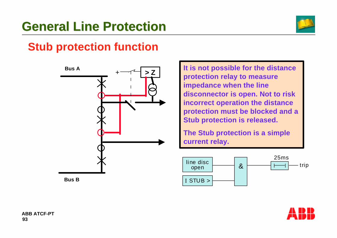
ABB ATCF-PT
General Line ProtectionGeneral Line Protection
93
Stub protection function
It is not possible for the distanceprotection relay to measureimpedance when the linedisconnector is open. Not to riskincorrect operation the distanceprotection must be blocked and aStub protection is released.
The Stub protection is a simplecurrent relay.
li ne discopen
I STUB >
& t rip25ms
Bus A
Bus B
> Z+

ABB ATCF-PT
General Line ProtectionGeneral Line Protection
94
14- Earth fault protection
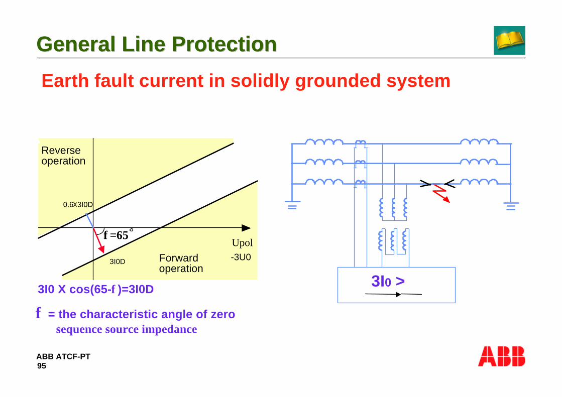
ABB ATCF-PT
General Line ProtectionGeneral Line Protection
95
Earth fault current in solidly grounded system
Reverseoperation
Forwardoperation
Upol-3U03I0D
0.6 3I0Dx
3I0 >3I0 X cos(65-φ)=3I0D
φ = the characteristic angle of zerosequence source impedance
φ=65

ABB ATCF-PT
General Line ProtectionGeneral Line Protection
96
• HIGH FAULT RESISTANCE CAN BE DIFFICULT TO DETECTTHROUGH DISTANCE RELAYS.
• THIS CAN BE OVERCOME BY E/F O/C PROTECTION EITHER NONDIRECTIONAL OR DIRECTIONAL.
• PROVIDED WITH SECOND HARMONIC CURRENT RESTRAINT WHICHBLOCKS OPERATION IF RESIDUAL CURRENT CONTAINS 20% ORMORE OF SECOND HARMONICS.
• POLARIZING VOLTAGE CAN HAVE HIGH AMOUNT OF HARMONICSWHEN OUTPUT VOLTAGE IS LOW PARTICULARLY WHEN CVTS AREPROVIDED. THEREFORE RELAY MUST HAVE BAND PASS FILTER.BAND PASS FILTER PROVIDES SECURE OPERATION DOWN TO 1%OF NOMINAL VOLTAGE.
EARTH FAULT CURRENT IN SOLIDLYGROUNDED SYSTEM.
ABB ATCF-PT
General Line ProtectionGeneral Line Protection
97
15- Auto reclosing

ABB ATCF-PT
General Line ProtectionGeneral Line Protection
98
1.0 GENERAL1.0 GENERAL
• The auto-reclosing of power lines has become a generally accepted practice.
• Reports from different parts of the world show that in certain networks in region subject to a high lightening intensity only about 5% of the faults are permanent.
• Auto reclosing therefore provides significant advantages.
• Outage times will be short compared to where station personnel have to re-energize the lines after a fault.
• In interconnected networks auto-reclosing helps in maintaining system stability

ABB ATCF-PT
General Line ProtectionGeneral Line Protection
99
1.1 Recommendations for provisions of auto-reclosing1.1 Recommendations for provisions of auto-reclosing
• Presently 1 phase high speed auto-reclosure (HSAR) at 400kV and 220kV level is widely practised including on lines emanating from Generating Stations and the same is recommended for adoption.
• If 3-phase auto-reclosure is adopted in future the application of the same on lines emanating from generating stations should be studied and decision taken on case to case basis.
ABB ATCF-PT
General Line ProtectionGeneral Line Protection
100
2.0 SETTING CRITERIA2.0 SETTING CRITERIA
2.1 Dead Time2.1 Dead Time
• Auto- reclosing requires a dead time which exceeds the de-ionising time
• Time required for the de-ionising of the fault path depends on:- arcing time, fault duration, wind conditions, circuit voltage, capacitive coupling to adjacent conductors, etc.
• Single phase dead time of 1.0 sec is recommended for both 400kV and 220kV system.

ABB ATCF-PT
General Line ProtectionGeneral Line Protection
101
2.2 Reclaim Time2.2 Reclaim Time
• The time during which a new start of the auto-reclosing equipment is blocked.
• If reclosing shot has been carried out and the line is energized and a new fault occurs before the reclaim time has elapsed, the auto-reclosing equipment is blocked and a signal for definite tripping of the breaker is obtained.
• After the reclaim time has elapsed, the auto-reclosing equipment returns to the starting position and a new reclosing sequence can occur.
• The reclaim time must not be set to such a low value that the intended operating cycle of the breaker is exceeded, when two faults incidents occur close together.

ABB ATCF-PT
General Line ProtectionGeneral Line Protection
102
• If the breaker is closed manually, the auto reclosing equipment is blocked and cannot start again until the reclaim time has elapsed.
• For the breaker to be used for auto-reclosing, it is essential that it has the operating mechanism and breaking capacity necessary for it to be able to perform the auto-reclosing sequences required.

ABB ATCF-PT
General Line ProtectionGeneral Line Protection
103
2.3 Circuit Breaker Requirement2.3 Circuit Breaker Requirement
• According to IEC Publication 56.2, a breaker must be capable of withstanding the following operating cycle with full rated breaking current:
O + 0.3 s + CO + 3 min + CO
• The recommended operating cycle at 400kV and 220kV is as per the IEC standard.
• Reclaim time of 25 sec is recommended.

ABB ATCF-PT
General Line ProtectionGeneral Line Protection
104


![Transmission Line Differential Protection Based on ...discussed line differential protection based on IEC 61850. In [9] an adaptive current line differential protection scheme is proposed](https://static.fdocuments.in/doc/165x107/5e7b1116957fb414ac4ec632/transmission-line-differential-protection-based-on-discussed-line-differential.jpg)