GENERAL INFORMATION - Mercer Valve · MERCER VALVE COMPANY, INC. Auto Seat Technology® GENERAL...
12
GENERAL INFORMATION MERCER VALVE THINK...MERCER FIRST™
Transcript of GENERAL INFORMATION - Mercer Valve · MERCER VALVE COMPANY, INC. Auto Seat Technology® GENERAL...

GENERAL INFORMATION
MER
CER
VA
LV
E
THINK...MERCER FIRST™

MERCER VALVE COMPANY, INC.Auto Seat Technology®GENERAL INFORMATION
MERCER VALVE COMPANY, INC.Auto Seat Technology®
GENERAL INFORMATION
2 www.mercervalve.net • 1.800.833.6402 www.mercervalve.net • 1.800.833.6402 3
Mercer Valve Company
1980sMercer valve was founded by Wesley Taylor with his Auto Seat Technology® patent for pressure relief valves.
Mercer’s first valve line was the 8100 Series introduced in 1985. Auto Seat Technology® is incorporated in the valve design, allowing it to pop and reseat time and time again. Unlike the competition, the valve has a soft seat design with a fully guided disk and spring to help the valve have a longer life.
With the introduction of our 8100 Series, Mercer Valve started a VR Certified Valve Repair Division. The repair division repairs all relief valve manufacturers and also has mobile units for on-site repair and testing. In addition to the VR shop, we have added an “ANSI” shop, repairing ball valves, orbit valves, gate valves, as well as many other kind of valves.
The 8700 Series was Mercer Valve’s next endeavor. This valve has the same guiding system as the 8100 Series, but incorporates a hard seat. The guiding system increases the repeatability of the valve opening and closing.
1990sMercer’s 9100 Series, the industrial pressure relief valve, was introduced in 1991. The 9100 Series was devel-oped to handle industrial gases and liquids, while continuing to use the proven design of Auto Seat Technology®. The 9100 Series also provides more options for the customer including different soft seat and seal materials, threaded and flanged connections, and sizes ranging from 1/2“x 1” to 4” x 6”.
In 1995, Mercer Valve added the 9100 Series Model 20 to their product line. This valve line is used for high pressure service up to 8700 psig set pressure.
Mercer Valve entered the pilot operated relief valve market with the 9500 Series. The 9500 Series includes API Orifice Sizes from “D” through “T” and Full Bore Orifices up to 8 inches. Mercer’s 9500 Series includes both a snap action pilot and a modulating action pilot. The modulating pilot is unlike any in the industry, having full modulation throughout the over pressure range. Continuing in the Mercer tradition, the 9500 Series has a long life due to the usage of Auto Seat Technology®.
With the growth and success of our valve lines, Mercer Valve moved in a new building. This houses the home office, repair division, and manufacturing department. The facilities also include an expanded fully functioning flow lab. Mercer Valve has always strived to be safe minded and engineer driven. The expanded flow lab has increased testing and enabled further research and development.
2000sIn 2000, Mercer opened a Houston Branch to help service our Houston customers more efficiently. The Houston Branch assembles valves keeping lead times at a minimum. The Houston Branch is also a VR Certified repair shop.
A few years later, Mercer opened a location in Calgary, AB, Canada to support our Canadian customers. Mercer Valve also opened a new repair center in Oklahoma City to accommodate the increasing repair business. The new repair center offers a larger area for the repair of other oilfield equipment including glycol pumps, chemical pumps, ball valves, gate valves, orbit valves, etc.
MERCER VALVE COMPANY, INC.Auto Seat Technology®GENERAL INFORMATION
MERCER VALVE COMPANY, INC.Auto Seat Technology®
GENERAL INFORMATION
2 www.mercervalve.net • 1.800.833.6402 www.mercervalve.net • 1.800.833.6402 3
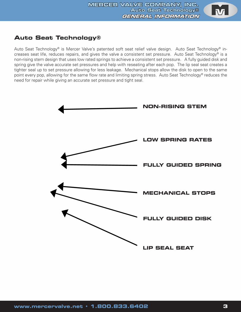
Auto Seat Technology®
Auto Seat Technology® is Mercer Valve’s patented soft seat relief valve design. Auto Seat Technology® in-creases seat life, reduces repairs, and gives the valve a consistent set pressure. Auto Seat Technology® is a non-rising stem design that uses low rated springs to achieve a consistent set pressure. A fully guided disk and spring give the valve accurate set pressures and help with reseating after each pop. The lip seal seat creates a tighter seal up to set pressure allowing for less leakage. Mechanical stops allow the disk to open to the same point every pop, allowing for the same flow rate and limiting spring stress. Auto Seat Technology® reduces the need for repair while giving an accurate set pressure and tight seal.
NON-RISING STEM
LOW SPRING RATES
FULLY GUIDED SPRING
MECHANICAL STOPS
FULLY GUIDED DISK
LIP SEAL SEAT

MERCER VALVE COMPANY, INC.Auto Seat Technology®GENERAL INFORMATION
MERCER VALVE COMPANY, INC.Auto Seat Technology®
GENERAL INFORMATION
4 www.mercervalve.net • 1.800.833.6402 www.mercervalve.net • 1.800.833.6402 5
NON-RISING STEM
The adjustment screw in the Mercer Valve is a non-rising stem, meaning that when adjusting the set pressure the adjustment screw does not move up or down. When the adjustment screw is turned, it moves the adjustment bushing straight up and down increasing and decreasing the tension in the spring. The adjust-ment bushing never turns. Because the adjustment bushing never turns, it does not transmit a torque into the disk and seat when adjusting the set pressure. This helps extend the seat life of the valve.
MECHANICAL STOPS
Due to Mercer Valve having a non-rising stem design the adjust-ment screw never moves up and down. Because the adjustment screw is always in the same place it can be used as a mechanical stop for the disk. This allows the disk to open the same amount each time the valve opens. This gives the valve the same capac-ity every pop. The mechanical stop is positioned so that the disk is always held up by the flow of the valve until the pressure drops low enough to reclose the valve. The mechanical stop also does not allow the spring to be over compressed, reducing stress on the spring.
FULLY GUIDED SPRING
The spring in the Mercer Valve is guided from top to bottom. With a fully guided spring the spring is only compressed vertically so the spring keeps consistent tension from one pop to the next.

MERCER VALVE COMPANY, INC.Auto Seat Technology®GENERAL INFORMATION
MERCER VALVE COMPANY, INC.Auto Seat Technology®
GENERAL INFORMATION
4 www.mercervalve.net • 1.800.833.6402 www.mercervalve.net • 1.800.833.6402 5
FULLY GUIDED DISK
The disk is aligned on the top through the adjustment screw and at the bottom of the disk by the radius on the disk. When a relief valve begins to vent, the flow of the valve pulls everything to-ward the outlet. Guiding the disk allows the disk to only move up and down and not to the sides. This keeps the disk from being pulled toward the outlet. With the disk only rising up and down the disk has a consistent opening and reseating. The radius on the bottom of the disk also helps insure that the valve reseats af-ter each pop. If the disk is not centered on the nozzle at reclose, the radius on the bottom of the disk helps to realign the disk. The spring force will push the disk down and the radius will allow the disk to roll back into place.
LOW SPRING RATES
A spring rate is the amount of force the spring exerts for how much it is compressed. Mercer Valve uses low rated springs to help keep stresses out of the spring. The more force that the spring is exerting, the higher the stresses in the spring. When a spring is over stressed the properties of the spring are changed, affecting the set pressure of the valve.
LIP SEAL SEAT
Mercer uses a lip seal soft seat. On reclose the seat flexes, allowing the brute impact of the disk reclosing to be taken by the hard nozzle, while still providing the soft seat seal. Also before the valve reaches set pressure, the pressure is applied underneath the lip seal, pushing the seat against the disk. This gives a tight seal up to the set pressure and extends the seat life.

MERCER VALVE COMPANY, INC.Auto Seat Technology®GENERAL INFORMATION
MERCER VALVE COMPANY, INC.Auto Seat Technology®
GENERAL INFORMATION
6 www.mercervalve.net • 1.800.833.6402 www.mercervalve.net • 1.800.833.6402 7
General Terms
Set Pressure is the point at which the pressure relief valve is set to open.
Over Pressure is the amount of pressure above the set pressure that is allowed for the valve to go to full lift and achieve full flow. For most applications this is typically 10% or 3psi, which ever is greater.
Conventional Pressure Relief Valve is a direct spring operated valve. The spring tension controls the opening and closing of the valve. The set pressure is affected by back pressure on this type of valve. Pilot Operated Pressure Relief Valve is a valve where the opening and closing of the main valve is controlled by an auxiliary pressure relief valve called a pilot. The main valve is the primary relief device.
Back Pressure is pressure on the outlet side of the valve. There are 2 types of back pressure, superimposed and built-up. Some types of back pressure can affect the flow rate and/or the set pressure.
Built-up Back Pressure is pressure in the outlet of the valve caused by the flow of the valve after the valve opens. This type of back pressure does not affect the set pressure.
Superimposed Back Pressure is the pressure on the outlet of the valve at the time the valve opens. This back pressure is caused by other sources and will affect the set pressure of a conventional pressure relief valve. Superimposed back pressure can be variable or constant.
Blowdown is the difference between when a valve opens (set pressure) and when the valve closes. Typically blowdown is expressed as a percentage of the set pressure.
Auto Seat Technology® is Mercer Valve’s patented soft seat relief valve design. Auto Seat Technology® increases seat life, reduces repairs, and gives the valve a consistent set pressure.
Common Codes and Standards
American Society of Mechanical Engineers Boiler and Pressure Vessel Code, Section VIII, Division 1 UG-125-136, Appendix II, Appendix M
American Petroleum Institute Recommended Practices 520 part I, 520 part II, and 521 & Standards 526, 527, and 2000
US Department of Transportation CFR Title 49, Chapter 1
Compressed Gas Association S-1.1, S-1.2, and S-1.3

MERCER VALVE COMPANY, INC.Auto Seat Technology®GENERAL INFORMATION
MERCER VALVE COMPANY, INC.Auto Seat Technology®
GENERAL INFORMATION
6 www.mercervalve.net • 1.800.833.6402 www.mercervalve.net • 1.800.833.6402 7
Sizing Overview
There are multiple ways of sizing a pressure relief valve depending on the type of system the valve is installed. In some cases multiple scenarios may be present and all cases should be considered. Pres-sure relief valves are sized to relieve a specified flow at the particular conditions of the system the valve is installed. The flow rate used in sizing the pressure relief valves is based on the amount needed to be relieved to prevent further overpressure of the system. The result of the pressure relief sizing gives a minimum required area to produce the required flow rate. The minimum required area is then used to select the proper orifice area for the valve.
Different standards and organizations have developed sizing methods and calculations. Two of the most common methods for blocked flow sizing are from American Society of Mechanical Engineers (ASME) and The American Petroleum Institute (API). The calculations are similar for both methods. The main difference between the methods is the discharge coefficient and orifice areas used. API uses generic values for both the discharge coefficient and orifice areas, while ASME uses the actual orifice area for the particular valve series and the measured discharge coefficient.
MERCER VALVE COMPANY, INC.Auto Seat Technology®GENERAL INFORMATION
MERCER VALVE COMPANY, INC.Auto Seat Technology®
GENERAL INFORMATION
8 www.mercervalve.net • 1.800.833.6402 www.mercervalve.net • 1.800.833.6402 9
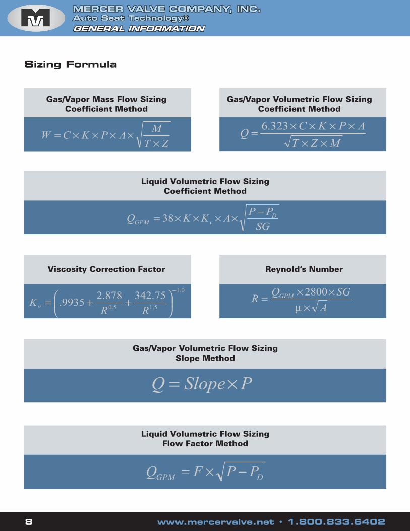
Gas/Vapor Mass Flow SizingCoefficient Method
Gas/Vapor Volumetric Flow SizingCoefficient Method
Liquid Volumetric Flow SizingCoefficient Method
Viscosity Correction Factor Reynold’s Number
Gas/Vapor Volumetric Flow SizingSlope Method
Liquid Volumetric Flow Sizing Flow Factor Method
ZTM
APKCW×
××××=MZT
APKCQ
××××××= 323.6
SGPP
AKKQ DvGPM
−××××= 38
0.1
5.15.0
75.342878.29935.
−
++=
RRKv A
SGQR GPM
×××=
µ2800
PSlopeQ ×=
DGPM PPFQ −×=
Sizing Formula

MERCER VALVE COMPANY, INC.Auto Seat Technology®GENERAL INFORMATION
MERCER VALVE COMPANY, INC.Auto Seat Technology®
GENERAL INFORMATION
8 www.mercervalve.net • 1.800.833.6402 www.mercervalve.net • 1.800.833.6402 9
Equation Variable Definitions
W = Mass Flow Rate (lbs/hr)
Q = Gas Volumetric Flow Rate (scfm)
QGPM = Liquid Flow Rate (GPM)
C = Gas Constant
K = Discharge Coefficient
P = Flowing Pressure, Set Pressure + Over Pressure + Atmospheric Pressure (psia)
PD = Pressure at the Discharge (psia)
A = Flow Area (in2)
M = Gas Molecular Weight
T = Temperature (ºR = ºF + 460)
Z = Gas Compressibility Factor
KV = Viscosity Correction Factor
F = ASME Flow Factor, (GPM/ (P-PD)
R = Reynold’s Number
µ = Viscosity at flowing temperature (cP)
SG = Specific Gravity

MERCER VALVE COMPANY, INC.Auto Seat Technology®GENERAL INFORMATION
MERCER VALVE COMPANY, INC.Auto Seat Technology®
GENERAL INFORMATION
To To ToMultiply By Obtain Multiply By Obtain Multiply By Obtain
psi 6.895 kPa kg / cm2 735.5591 mm Hg mm2 0.000001 m2
psi 0.068 atm kg / cm2 393.7008 in H2O cm2 0.0001 m2
psi 0.0689 bar in Hg 25.4 mm Hg in3 0.000579 ft3
psi 0.0703 kg / cm2 in Hg 13.595 in H2O in3 16387.064 mm3
psi 2.036 in Hg mm Hg 0.5352 in H2O in3 16.387064 cm3
psi 51.715 mm Hg in 0.08333 ft in3 0.000016 m3
psi 27.679 in H2O in 25.4 mm ft3 28316846.59 mm3
kPa 0.009869 atm in 2.54 cm ft3 28316.8466 cm3
kPa 0.01 bar in 0.0254 m ft3 0.028317 m3
kPa 0.0102 kg / cm2 ft 304.8 mm mm3 0.001 cm3
kPa 0.2953 in Hg ft 30.48 cm mm3 0.000000001 m3
kPa 7.5006 mm Hg ft 0.3048 m cm3 0.000001 m3
kPa 4.0146 in H2O mm 0.1 cm ounce 0.02835 kgatm 1.01325 bar mm 0.001 m slug 14.5939 kgatm 1.0332 kg / cm2 cm 0.01 m slug 514.785 ounceatm 29.92126 in Hg in2 0.006944 ft2 lb 0.031081 slugatm 759.999 mm Hg in2 645.16 mm2 lb 0.453592 kgatm 406.7825 in H2O in2 6.4516 cm2 lb 16 ouncebar 1.0197 kg / cm2 in2 0.000645 m2 cfm 1.699 m3 / hrbar 29.52999 in Hg ft2 92903.04 mm2 GPM 34.2857 BPDbar 750.0616 mm Hg ft2 929.0304 cm2 GPM 227.1247 LPHbar 401.4631 in H2O ft2 0.092903 m2 BPD 6.624471 LPHkg / cm2 28.959 in Hg mm2 0.01 cm2 lb / hr 0.453592 kg / hr
Unit Conversion
Acetylene 26.038 1.231 340 Methanol 32.042 1.227 340Air 28.97 1.4 356 Natural Gas 17.4 1.27 344Ammonia 17.031 1.297 347 Neon 20.183 1.667 378Argon 39.948 1.667 378 Nitric Oxide 30.006 1.387 355Butane 58.124 1.091 326 Nitrogen 28.013 1.4 356Carbon Monoxide 28.01 1.399 356 Nitrous Oxide 44.013 1.274 345Carbon Dioxide 44.01 1.289 346 Octane 114.23 1.044 321Ethane 30.07 1.186 336 Oxygen 31.999 1.393 355Ethanol 46.069 1.145 332 Propane 44.094 1.126 330Ethylene 28.054 1.237 341 R-12 120.914 1.126 330Helium 4.003 1.667 378 R-22 86.469 1.171 334Hydrogen 2.016 1.409 357 R-134a 102.03 1.106 327Methane 16.043 1.299 347 Sulfur Dioxide 64.059 1.263 343
Gas Proterties
GasMolecular
Weight
Ratio of Specifc
Heats (k)
Gas Constant
(C) GasMolecular
Weight
Ratio of Specifc
Heats (k)
Gas Constant
(C)
10 www.mercervalve.net • 1.800.833.6402 www.mercervalve.net • 1.800.833.6402 11

MERCER VALVE COMPANY, INC.Auto Seat Technology®GENERAL INFORMATION
MERCER VALVE COMPANY, INC.Auto Seat Technology®
GENERAL INFORMATION
10 www.mercervalve.net • 1.800.833.6402 www.mercervalve.net • 1.800.833.6402 11
Discharge Coefficients
.800* .639* 3.10 5.15 .975 .650
.830* .711* 7.21 12.77 .975 .650
.818 .707 --- --- .975 .650
.818 .707 --- --- .975 .650
.854* --- 1.91 --- .975 ---
.870 .731 --- --- .975 .650
.820 --- --- --- .975 ---
* = 8100 Series and 8700 Series are certified under the slope method. The discharge coefficients for these orifices have been calculated from the slopes and Flow Factors.
Valve
Series
ASME
Gas/Vapor
Discharge
Coefficient
ASME
Liquid
Discharge
Coefficient
ASME
Gas/Vapor
Slope
ASME
Liquid
Flow
Factor
API
Gas/Vapor
Discharge
Coefficient
API
Liquid
Discharge
Coefficient
8100 Series 1/2” Diameter
Orifice
8100 Series 3/4” Diameter
Orifice
9100 Series
9100 Series Model 20
8700 Series
9500 Series API Orifice
Letters
9500 Series Full Bores
GENERAL INFORMATION
CORPORATE HEADQUARTERS9609 NW 4th STREETOKLAHOMA CITY, OK 731271-800-833-6402PHONE: (405) 495-6533, FAX: (405) [email protected]
HOUSTON BRANCH OFFICE6218 LONG DRIVEHOUSTON, TX 770871-866-833-6402PHONE: (713) 242-6960, FAX: (713) [email protected]
CALGARY BRANCH OFFICE#203, 2835 23rd St. NECALGARY, ALBERTA T2E 7A4PHONE: (403) 250-5557, FAX: (403) [email protected]
CHICAGO BRANCH OFFICECUSTOMER RELATIONS DEPARTMENTP.O. Box 597Libertyville, IL [email protected]
WWW.MERCERVALVE.NET
MV-GEN 1 REVISION DATE: 4/07 SUPERCEDES 11/03