Unique Valve Seat Design
21
16 T: 936-588-8380 • F: 936-588-8381 • www.craneenergy.com Unique Valve Seat Design Fire Flow The Flowseal Fire-Flow™ high performance butterfly valve (HPBFV) is a fire-safe, soft seat quarter-turn valve. The Fire-Flow™ design incorporates two patented seats which function together to seal off pipeline flow. In normal operation, the soft seat provides a bi-directional “bubble tight” shutoff (zero leakage); the metal seat provides bi- directional shutoff in the event of a fire, in conformance to industry fire-safe requirements. With little or no pressure, the Fire-Flow seat creates a self-energized seal against the disc. Higher line pressures act on the geometry of both seats to dynamically load them against the disc, creating higher sealing forces in either direction. The Fire-Flow™ metal seat is made of Inconel material which is shaped by a proprietary hydroforming process into its unique, patented design. Stainless steel outer bearings are included for post-fire disc and shaft alignment.Fireproof packing is used to prevent external shaft leakage. “O” Ring Soft Seat Metal Seat Disc Metal Seat Gasket
Transcript of Unique Valve Seat Design

16T: 936-588-8380 • F: 936-588-8381 • www.craneenergy.com
Unique Valve Seat DesignFire Flow
The Flowseal Fire-Flow™ high performance butterflyvalve(HPBFV) isafire-safe,softseatquarter-turnvalve.TheFire-Flow™design incorporates twopatentedseatswhichfunctiontogethertosealoffpipelineflow.Innormaloperation, the soft seat provides a bi-directional “bubbletight” shutoff (zero leakage); themetal seat provides bi-directionalshutoffintheeventofafire,inconformancetoindustryfire-saferequirements.
Withlittleornopressure,theFire-Flowseatcreatesaself-energizedsealagainstthedisc.Higherlinepressuresactonthegeometryofbothseatstodynamicallyloadthemagainst the disc, creating higher sealing forces in eitherdirection.
TheFire-Flow™metalseatismadeofInconelmaterialwhichisshapedbyaproprietaryhydroformingprocessintoitsunique,patenteddesign.Stainlesssteelouterbearingsareincludedforpost-firediscandshaftalignment.Fireproofpackingisusedtopreventexternalshaftleakage.
“O” Ring
Soft Seat
Metal Seat
Disc
Metal Seat Gasket
17T: 936-588-8380 • F: 936-588-8381 • www.craneenergy.com
Principle of Seat Sealing Fire Flow
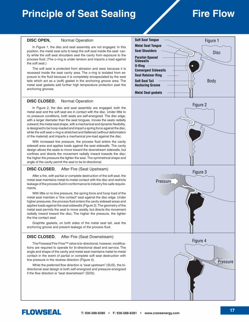
DISC OPEN, NormalOperation
InFigure1,thediscandseatassemblyarenotengaged.Inthisposition,themetalseatactstokeepthesoftseatinsidetheseatcav-itywhilethesoftseatshoulderssealthecavityfromexposuretotheprocessfluid.(Theo-ringisundertensionandimpartsaloadagainstthesoftseat.)
Thesoftseat isprotectedfromabrasionandwearbecauseit isrecessedinsidetheseatcavityarea.Theo-ring is isolatedfromex-posuretothefluidbecauseitiscompletelyencapsulatedbytheseattailswhichactasa(soft)gasket in theanchoringgroovearea.Themetalseatgasketsaddfurtherhightemperatureprotectionpasttheanchoringgrooves.
DISC CLOSED, AfterFire(SeatDownstream)
TheFlowsealFire-Flow™valveisbi-directional,however,modifica-tionsarerequiredtooperateforbi-directionaldeadendservice.Theangleandshapeofthecavityandmetalseatmaintainsmetal-to-metalcontactintheeventofpartialorcompletesoftseatdestructionwithlinepressureinthereversedirection(Figure4).
Whilethepreferredflowdirectionis“seatupstream”(SUS),thebi-directionalseatdesignisbothself-energizedandpressure-energizediftheflowdirectionis“seatdownstream”(SDS).
DISC CLOSED, NormalOperation
In Figure 2, the disc and seat assembly are engaged; both themetalseatandthesoftseatareincontactwiththedisc.Underlittletonopressureconditions,bothseatsareself-energized.Thediscedge,withalargerdiameterthantheseattongues,movestheseatsradiallyoutward;themetalseatshape,withamechanicalanddynamicflexibility,isdesignedtobehoop-loadedandimpartaspringforceagainstthedisc,whilethesoftseato-ringisstretchedandflattened(withoutdeformationofthematerial)andimpartsamechanicalpre-loadagainstthedisc.
With increased linepressure, theprocess fluidenters the cavitysidewallareaandappliesloadsagainsttheseatsidewalls.Thecavitydesignallowstheseatstomovetowardthedownstreamsidewalls,butconfinesanddirects themovement radially inward towards thedisc;thehigherthepressurethetightertheseal.Thesymmetricalshapeandangleofthecavitypermitthesealtobebi-directional.
DISC CLOSED, AfterFire(SeatUpstream)
Afterafire,withpartialorcompletedestructionofthesoftseat,themetalseatmaintainsmetal-to-metalcontactwiththediscandrestrictsleakageoftheprocessfluidinconformancetoindustryfire-saferequire-ments.
Withlittleornolinepressure,thespringforceandhooploadofthemetalseatmaintaina“linecontact”sealagainstthediscedge.Underhigherpressures,theprocessfluidentersthecavitysidewallareasandappliesloadsagainsttheseatsidewalls(Figure3).Thegeometryofthemetalseatpermitstheseattomoveaxially,butdirectsthemovementradially inward toward thedisc;Thehigher thepressure, the tighterthelinecontactseal.
Graphitegaskets,onbothsidesof themetal seat tail, seal theanchoringgrooveandpreventleakageoftheprocessfluid.
Disc
Body
Soft Seat Tongue
Metal Seat TongueSeat Shoulders
Parallel-SpacedSidewallsO-RingConvergent SidewallsSeat Retainer Ring
Soft Seat Tail
Metal Seat gaskets
Figure 1
Figure 2
Figure 3
Figure 4
Pressure
Anchoring Groove
Pressure

18T: 936-588-8380 • F: 936-588-8381 • www.craneenergy.com
Valve ComponentsFire Flow
TheASME15030"through48";ASME30014"through30";ASME60010"through16"sizesfeatureatwo-pieceshaft
designwhichutilizesalowerpackingsealinthevalvebodytopreventexternalleakage.Thecomponentpartsareofthesamedesignusedinthepackingassemblyinthetopofthevalvebodyneck.
DISCFire-Flowdisciselectrolessnickelplatedforenhancedtemperatureandabrasionresistance.
WEDGE PINSProvidepositivemechanicalattachmentofdisctoshaft.
PACKING GLANDSeparatepartfromglandflange,prevent-ingunevenloaddistributionagainstpacking.
BODYASMEB16.34designineitherwaferorlugconfiguration.
KEYSquarekeyvalve-to-operatorconnectionprovidesanexternallycontrolledfailurepointuponover-torquing.
PACKINGCommonmaterialisgraphite
GLAND FLANGEAppliesloadagainstpackingglandtopreventexternalleakage.Fullyadjustable.
SHAFTSolidshaftprovidesalignmentandrigidsupportfordisc.
OUTER BEARINGSStainlesssteelback-upbearingsmaintainshaftalignmentafterafire.(Bothaboveandbelowdisc.)
INNER BEARINGSBothaboveandbelowthedisc,bearingsareofcompositedesign:TFEbondedtoepoxy-glassfilamentwoundring.Usedtoalignshaft,withhighloadcapacity,lowwearandlowfrictioncoefficient.
TheASME15014"through24"sizesfeatureatwo-pieceshaftdesign.Thelowershaftutilizesan
endsealinthebodytopreventexternalleak-age.Thecomponentpartsincludean endseal,anendcapandendcapbolts.
End Seal Variation Lower Packing Variation
OVERTRAVEL STOPPreventsdiscfromrotatingintowrongquadrant.
WEDGE RINGStainlesssteelbandwedgedbetweenvalvebodyandretainerringbysetscrewstolockseatandretainerringinpositiononvalvesizes2"through30".Socketheadcapscrewsareusedonvalvesizes36"andlarger.
SET SCREWSConepointscrewsforcewedgeringoutwardtolockseatretainerinpositiononvalvesizes2"through30"wafer.Socketheadcapscrewsareusedonvalvesizes36"andlargerandallDDESlugvalves. FIRE–FLOW SEAT
Patentedbi-directionalsoftseatdesignforzero-leakageinnormaloperationandametal-to-metalsealafterfire,meetingorexceedingindustry“fire-safe”specifications.
RETAINER RINGRetainsseatinvalve.Standardsurfacefinishis125to200AARHandiscompat-iblewithbothstandardgasketsandspiralwoundgasketdesigns.Outsidediameterisrecessedwithingasketsealingsurfacetopreventexternalleakage.
DISC SPACERSDisciscenteredbyuseofthrustspacersaroundshaftinsizes2"to5".Discpositionstopsorthrustboltarrangementsareusedforlargervalvesizes.
19T: 936-588-8380 • F: 936-588-8381 • www.craneenergy.com
Pressure/Temperature Ratings
Fire Flow
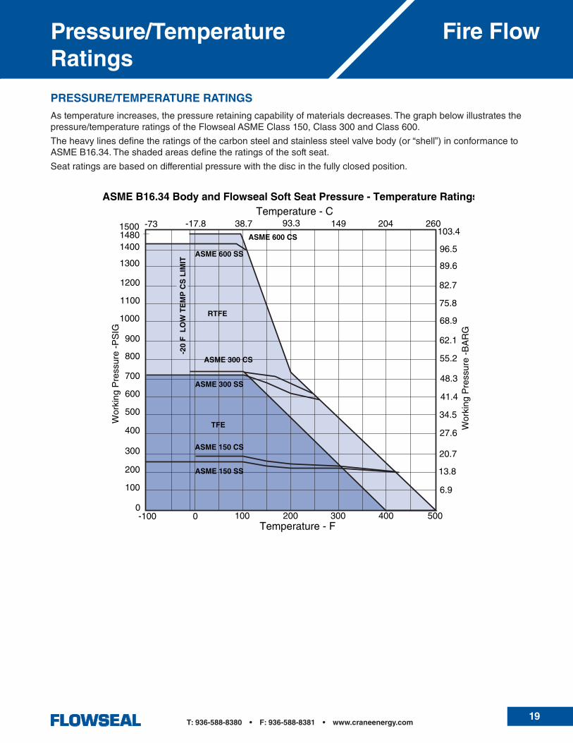
PRESSURE/TEMPERATURE RATINGS
Astemperatureincreases,thepressureretainingcapabilityofmaterialsdecreases.Thegraphbelowillustratesthepressure/temperatureratingsoftheFlowsealASMEClass150,Class300andClass600.
Theheavylinesdefinetheratingsofthecarbonsteelandstainlesssteelvalvebody(or“shell”)inconformancetoASMEB16.34.Theshadedareasdefinetheratingsofthesoftseat.
Seatratingsarebasedondifferentialpressurewiththediscinthefullyclosedposition.
20T: 936-588-8380 • F: 936-588-8381 • www.craneenergy.com
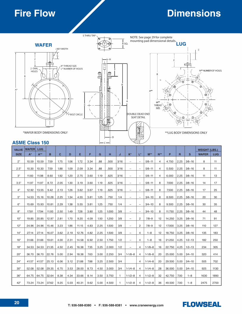
DimensionsFire Flow
VALVE WEIGHT (LBS.)
SIZE A* A** B C D E F G H J K* L* M** N** P R S WAFER LUG
2" 10.59 10.59 7.59 1.75 1.06 1.72 3.34 .88 .500 3/16 – – 5⁄8–11 4 4.750 2.25 3⁄8–16 8 11
2.5" 10.30 10.30 7.59 1.88 1.09 2.09 3.34 .88 .500 3/16 – – 5⁄8–11 4 5.500 2.25 3⁄8–16 8 11
3" 11.60 11.98 8.60 1.92 1.20 2.75 3.60 1.19 .625 3/16 – – 5⁄8–11 4 6.000 2.25 3⁄8–16 11 13
3.5" 11.97 11.97 8.72 2.05 1.30 3.19 3.60 1.19 .625 3/16 – – 5⁄8–11 8 7.000 2.25 3⁄8–16 14 17
4" 12.92 13.55 9.42 2.13 1.26 3.62 3.67 1.19 .625 3/16 – – 5⁄8–11 8 7.500 2.25 3⁄8–16 17 25
5" 14.53 15.16 10.28 2.25 1.34 4.55 3.81 1.25 .750 1/4 – – 3⁄4–10 8 8.500 2.25 3⁄8–16 20 30
6" 15.69 15.93 10.81 2.29 1.38 5.55 3.81 1.25 .750 1/4 – – 3⁄4–10 8 9.500 2.25 3⁄8–16 30 35
8" 17.81 17.94 11.93 2.50 1.49 7.28 3.80 1.25 1.000 3/8 – – 3⁄4–10 8 11.750 2.25 3⁄8–16 44 48
10" 19.85 20.85 12.97 2.81 1.70 9.20 4.09 1.50 1.250 3/8 – 2 7⁄8–9 12 14.250 3.25 3⁄8–16 71 91
12" 24.96 24.96 15.46 3.23 1.86 11.15 4.83 2.25 1.500 3/8 – 2 7⁄8–9 12 17.000 3.25 3⁄8–16 110 127
14" 27.14 27.14 16.07 3.62 2.19 12.76 4.82 2.25 1.500 3/8 – 4 1–8 12 18.750 3.25 3⁄8–16 135 183
16" 31.66 31.66 19.61 4.00 2.31 14.58 6.92 2.50 1.750 1/2 – 4 1–8 16 21.250 4.25 1⁄2–13 182 250
18" 34.53 34.53 21.35 4.50 2.45 16.38 7.35 3.25 2.000 1/2 – 4 1-1⁄8–8 16 22.750 4.25 1⁄2–13 234 305
20" 36.70 36.70 22.76 5.00 2.94 18.38 7.63 3.00 2.250 3/4 1-1⁄8–8 4 1-1⁄8–8 20 25.000 5.00 3⁄4–10 320 414
24" 41.57 41.57 25.13 6.06 3.12 21.88 7.88 3.25 2.500 3/4 4 1-1⁄4–8 20 29.500 5.00 3⁄4–10 505 702
30" 52.08 52.08 29.35 6.75 3.53 28.00 8.73 4.50 3.000 3/4 1-1⁄4–8 4 1-1⁄4–8 28 36.000 5.00 3⁄4–10 925 1130
36" 64.75 64.75 32.64 8.38 4.34 33.66 8.14 3.50 3.750 1 1-1⁄2–8 4 1-1⁄2–8 32 42.750 7.00 1–8 1630 1890
42" 73.24 73.24 37.62 9.25 5.03 40.31 9.62 5.00 4.500 1 1-1⁄2–8 4 1-1⁄2–8 36 49.500 7.00 1–8 2475 2700
ASME Class 150 WAFER LUG
WAFER LUG
A
B
F
R SQ.
S THRU TAP
H
D
C
E
B
A**
F
N** NUMBER OF HOLES
**LUG BODY DIMENSIONS ONLY
M** THREAD
SIZE
*WAFER BODY DIMENSIONS ONLY **LUG BODY DIMENSIONS ONLY
DOUBLE DEAD END SEAT DETAIL
NOTE: See page 29 for complete mounting pad dimensional details.
*WAFER BODY DIMENSIONS ONLY
K* THREAD SIZEL* NUMBER OF HOLES
G
F
B
A*
P BOLT CIRCLE
2 OVALHOLES
J KEY WIDTH

21T: 936-588-8380 • F: 936-588-8381 • www.craneenergy.com
Dimensions Fire Flow
ASME Class 600
NOTES:1. General a. StandardvalvestestedtoMSSSP-61.API598testingavailableonrequest. b. Dimensionsshownareforreferenceonly.Certifieddrawingsavailableonapplication.
2. For 2" through 24" sizes: a. Face-to-facedimensions(C)meet,withinspecifiedtolerance,MSSSP-68andAPI609requirements. b. ValvesaredesignedforinstallationbetweenASMEB16.5flanges.
3. For 30" through 48" sizes: a. ValvesaredesignedforinstallationbetweenMSSSP-44andASMEB16.47flanges.
ASME Class 300 WAFER LUG
WEIGHT (LBS.)
VALVESIZE
A* A** B C D E F G H J K* L* M** N** P R S WAFER LUG
2" 10.59 10.59 7.59 1.75 1.06 1.72 3.34 .88 .500 3/16 – – 5/8–11 8 5.000 2.25 3⁄8–16 8 11
2.5" 10.30 10.30 7.59 1.88 1.09 2.09 3.34 .88 .500 3/16 – – 3⁄4–10 8 5.880 2.25 3⁄8–16 8 11
3" 11.60 11.98 8.60 1.92 1.20 2.75 3.60 1.19 .625 3/16 – – 3⁄4–10 8 6.625 2.25 3⁄8–16 12 17
3.5" 11.97 11.97 8.72 2.05 1.30 3.19 3.60 1.19 .625 3/16 – – 3/4-10 8 7.250 2.25 3/8-16 14 19
4" 12.92 13.54 9.42 2.13 1.25 3.62 3.67 1.19 .625 3/16 – – 3⁄4–10 8 7.875 2.25 3⁄8–16 17 24
5" 14.53 15.16 10.28 2.25 1.34 4.55 3.81 1.25 .750 1/4 – – 3⁄4–10 8 9.250 2.25 3⁄8–16 20 30
6" 15.93 16.31 10.81 2.29 1.38 5.55 3.81 1.25 1.000 3/8 – – 3⁄4–10 12 10.625 2.25 3⁄8–16 30 49
8" 18.10 19.50 12.22 2.88 1.54 7.06 4.08 1.50 1.250 3/8 – – 7⁄8–9 12 13.000 3.25 3⁄8–16 52 80
10" 21.60 22.10 14.22 3.25 1.70 9.00 4.84 2.25 1.500 3/8 1–8 2 1–8 16 15.250 3.25 3⁄8–16 88 115
12" 28.40 28.40 17.90 3.62 1.86 10.72 6.90 2.50 1.750 1/2 1-1⁄8–8 4 1-1⁄8–8 16 17.750 4.25 1⁄2–13 153 199
14" 34.31 34.31 19.74 4.62 2.48 12.08 7.36 3.25 2.000 1/2 1-1⁄8–8 4 1-1⁄8–8 20 20.250 4.25 1⁄2–13 285 324
16" 38.14 38.14 21.82 5.25 2.59 13.72 7.82 3.00 2.250 3/4 1-1⁄4–8 4 1-1⁄4–8 20 22.500 5.00 3⁄4–10 336 401
18" 40.26 40.26 23.00 5.88 3.03 15.56 7.87 3.25 2.500 3/4 1-1⁄4–8 4 1-1⁄4–8 24 24.750 5.00 3⁄4–10 393 517
20" 43.62 43.62 25.13 6.31 3.24 17.22 8.74 4.50 3.000 3/4 1-1⁄4–8 4 1-1⁄4–8 24 27.000 5.00 3⁄4–10 510 735
24" 49.94 49.94 28.27 7.19 3.62 20.61 8.89 4.00 3.500 1 1-1⁄2–8 4 1-1⁄2–8 24 32.000 7.00 1–8 733 1020
30" 62.40 62.40 31.90 8.88 4.39 27.25 9.02 5.00 4.500 1 1-3⁄4–8 4 1-3⁄4–8 28 39.250 7.00 1–8 1745 2145
WAFER LUGVALVESIZE
WEIGHT (LBS.)
A* A** B C D E F G H J K* L* M** N** P R S WAFER LUG
2" 10.59 10.59 7.59 1.75 1.06 1.72 3.34 – .500 – – – 5/8–11 8 5.000 2.25 3⁄8–16 11 13
3" 11.60 12.10 8.60 2.12 1.20 2.50 3.60 1.19 .625 3/16 – – 3⁄4–10 8 6.625 2.25 3⁄8–16 13 18
4" 14.43 14.93 9.81 2.50 1.40 3.43 3.81 1.25 .750 1/4 – – 7⁄8–9 8 8.500 2.25 3⁄8–16 30 52
6" 17.27 18.46 11.71 3.06 1.68 5.18 4.09 1.50 1.250 3/8 1–8 2 1–8 12 11.500 3.25 3⁄8–16 42 85
8" 21.35 22.00 13.97 4.00 1.85 6.28 4.84 2.25 1.500 3/8 1-1⁄8–8 – 1-1⁄8–8 12 13.750 3.25 3⁄8–16 72 127
10" 31.15 31.15 17.90 4.62 2.00 7.95 6.90 2.50 1.750 1/2 1-1⁄4–8 4 1-1⁄4–8 16 17.000 4.25 1⁄2–13 170 233
12" 34.80 34.80 20.13 5.50 2.53 9.68 7.50 3.00 2.250 3/4 1-1⁄4–8 4 1-1⁄4–8 20 19.250 5.00 3⁄4–10 245 379
22T: 936-588-8380 • F: 936-588-8381 • www.craneenergy.com
Valve Flow CoefficientsFlowseal
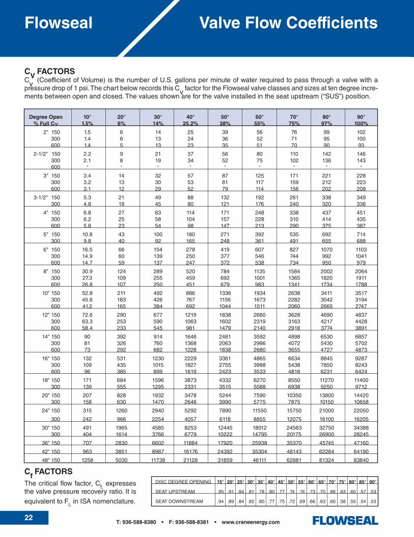
CV FACTORSCv (CoefficientofVolume)isthenumberofU.S.gallonsperminuteofwaterrequiredtopassthroughavalvewithapressuredropof1psi.ThechartbelowrecordsthisCvfactorfortheFlowsealvalveclassesandsizesattendegreeincre-mentsbetweenopenandclosed.Thevaluesshownareforthevalveinstalledintheseatupstream(“SUS”)position.
Cf FACTORSThecriticalflowfactor,Cf,expressesthevalvepressurerecoveryratio.ItisequivalenttoFLinISAnomenclature.
DISCDEGREEOPENING 15° 20° 25° 30° 35° 40° 45° 50° 55° 60° 65° 70° 75° 80° 85° 90°
SEATUPSTREAM .95 .91 .84 .81 .78 .80 .77 .74 .74 .73 .70 .66 .63 .60 .57 .53
SEATDOWNSTREAM .94 .89 .84 .82 .80 .77 .75 .72 .69 .66 .63 .60 .58 .55 .54 .53
Degree Open 10° 20° 30° 40° 50° 60° 70° 80° 90° % Full CV 1.5% 6% 14% 25.2% 38% 55% 75% 97% 100%
2" 150 1.5 6 14 25 39 56 76 99 102 300 1.4 6 13 24 36 52 71 95 100 600 1.4 5 13 23 35 51 70 90 93
2-1/2" 150 2.2 9 21 37 56 80 110 142 146 300 2.1 8 19 34 52 75 102 136 143 600 - - - - - - - - -
3" 150 3.4 14 32 57 87 125 171 221 228 300 3.2 13 30 53 81 117 159 212 223 600 3.1 12 29 52 79 114 156 202 208
3-1/2" 150 5.3 21 49 88 132 192 261 338 349 300 4.8 19 45 80 121 176 240 320 336
4" 150 6.8 27 63 114 171 248 338 437 451 300 6.2 25 58 104 157 228 310 414 435 600 5.8 23 54 98 147 213 290 375 387
5" 150 10.8 43 100 180 271 392 535 692 714 300 9.8 40 92 165 248 361 491 655 688
6" 150 16.5 66 154 278 419 607 827 1070 1103 300 14.9 60 139 250 377 546 744 992 1041 600 14.7 59 137 247 372 538 734 950 979
8" 150 30.9 124 289 520 784 1135 1584 2002 2064 300 27.3 109 255 459 692 1001 1365 1820 1911 600 26.8 107 250 451 679 983 1341 1734 1788
10"150 52.8 211 492 886 1336 1934 2638 3411 3517 300 45.6 183 426 767 1156 1673 2282 3042 3194 600 41.2 165 384 692 1044 1511 2060 2665 2747
12"150 72.6 290 677 1219 1838 2660 3628 4690 4837 300 63.3 253 590 1063 1602 2319 3163 4217 4428 600 58.4 233 545 981 1479 2140 2918 3774 3891
14"150 90 392 914 1646 2481 3592 4898 6530 6857 300 81 326 760 1368 2063 2986 4072 5430 5702 600 73 292 682 1228 1838 2680 3655 4727 4873
16"150 132 531 1230 2229 3361 4865 6634 8845 9287 300 109 435 1015 1827 2755 3988 5438 7850 8243 600 96 385 899 1619 2423 3533 4818 6231 6424
18"150 171 684 1596 3873 4332 6270 8550 11270 11400 300 139 555 1295 2331 3515 5088 6938 9250 9712
20"150 207 828 1932 3478 5244 7590 10350 13800 14420 300 158 630 1470 2646 3990 5775 7875 10150 10658
24"150 315 1260 2940 5292 7890 11550 15750 21000 22050
300 242 966 2254 4057 6118 8855 12075 16100 16205
30"150 491 1965 4585 8253 12445 18012 24563 32750 34388 300 404 1614 3766 6779 10222 14795 20175 26900 28245
36"150 707 2830 6602 11884 17920 25938 35370 45745 47160
42"150 963 3851 8987 16176 24392 35304 48143 62264 64190
48"150 1258 5030 11738 21128 31859 46111 62881 81324 83840
23T: 936-588-8380 • F: 936-588-8381 • www.craneenergy.com
FLOWSEAL ACTUATOR OPTIONS:
Lever: NotrecommendedforMetalSeat HighPerformanceButterflyValveGear Five types available: Operators: •Hightemperatureservice •Buriedservice •Submersibleservice •Marineservice •Standardaluminumhandwheel Optional: •Chainwheel •Outputshaftextension •Inputshaftextension •Militaryspecialoperator •AWWAspecialoperatorHydraulic Actuator: CustomerspecifiedhydraulicactuatorPneumatic Actuators:CraneRevo®springreturnpneumaticactuatorCraneRevo®doubleactingpneumaticactuatorCustomerspecifiedpneumaticactuatorElectric Actuators:Series44000electricactuatorCustomerspecifiedelectricactuator
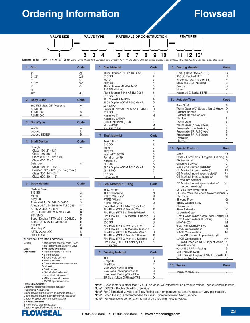
Ordering Information Flowseal
1. Size Code
2" 02 21/2" 025 3" 03 31/2" 035 4" 04 to 48" 48
2. Body Class Code
150PSIMax.Diff.Pressure 0 ASME150 1 ASME300 3 ASME600 6
3. Body Type Code
Wafer W Lugged L LuggedDDES2 D
4. Shaft Design Code
Straight A Class1502"-12" Class15036"-48" Class3002"-12"&30" Class6002"-8" Balanced C Class15014"-30" Derated36"-48"(150psigmax.) Class30014"-24" Class60010"-16"
5. Body Material Code
CarbonSteel 1 316SS 2 Monel 3 Alloy20 4 AnnealedALBr.MIL-B-24480 5 AnnealedALBr.B148ASTMC958 8 ASTMA744CN-3MN A 2205DuplexASTMA890Gr4A B 254SMO C SuperDuplexASTMA351CD4MCu D Steel,ASTMA217,GradeC5 E 317SS F HastelloyC H ASTMA352LCC L 304SS(CF8) N
6. Disc Material Code
AlumBronze/ENPB148C958 0 316SS 2 Monel 3 Alloy20 4 AlumBronzeMIL-B-24480 5 316SSNitrided 7 AlumBronzeB148ASTMC958 8 316SS/ENP 9 ASTMA744CN-3MN A 2205DuplexASTMA890Gr4A B 254SMO C SuperDuplexASTMA351CD4MCu D 317SS F HastelloyC H HastelloyC/ENP J 304SSNitrided(CF8) L Monel/ENP M 304SS(CF8) N
7. Shaft Material Code
17-4PHSS1 1 316SS 2 Monel1 3 Alloy20 4 Inconel718/750 6 FerraliumA479 7 Nitronic50 0 AL-6XN A 2205DuplexASTMA890Gr4A B 254SMO C 317SS F HastelloyC H
8. Seat Material / O-Ring Code
TFE/Viton4 T TFE/Neoprene N RTFE/Silicone5 R RTFE/Viton4 P RTFE/AFLAS O Polyethylene(UHMWPE)/Viton4 L Fire-Flow(TFE&Metal)/Viton4 F Fire-Flow(RTFE&Metal)/Viton4 A Fire-Flow(RTFE&Metal)/Silicone B Inconel M 300SS S Fire-Flow(TFE&Monel)/Viton4 C Fire-Flow(RTFE&Monel)/Silicone J Fire-Flow(RTFE&Monel)/Viton4 H Fire-Flow(TFE&Metal)/Silicone E Fire-Flow(TFE&Monel)/Silicone V Fire-Flow(RTFE&HastelloyC)/ K Silicone
9. Packing Material Code
TFE T Graphite G Fire-Flow F Live-LoadPacking/TFE A Live-LoadPacking/Graphite B Live-LoadPacking/Fire-Flow C EFSeal(VitonO-Rings)/TFE D
10. Bearing Material Code
Garfil(GlassBackedTFE) G 316SSBackedTFE H Fire-Flow(Garfil&316SS) F StainlessSteelNitrided S Bronze B Monel K HastelloyCBackedTFE J
11. Actuator Type Code
BareShaft B WormGearw/2"SquareNut&Hndwl D RatchetHandle H RatchetHandlew/Lock L Throttle T WormGear 3 WormGear(4-waykeyed) 9 PneumaticDoubleActing 4 PneumaticSRFailClose 5 PneumaticSRFailOpen 6 Hydraulic 7 Electric 8
12. Special Feature Code
None O Level2CommercialOxygenCleaning A Bi-directional B ChlorineService C Dead-endService(DDES)2 D CEMarked(impacttested)3 PI CEMarked(non-impacttested)3 PN CEMarked(impacttestedw/ VI vacuumservice)3
CEMarked(non-impacttestedw/ VN vacuumservice)3
EFSeal(lowemissions) E EFSealVacuumService(lowemissions)EV FlatFace F SiliconeFree G EpoxyCoatedBody H Chainwheel J StemExtension K LockableGear L LimitSwitchw/StainlessSteelBolting L1 LimitSwitchw/MonelBolting L2 Mil-V-24624 M GearwithMemoryStop MS NACEConstruction5 N NACEConstruction NI (w/CEmarkedimpacttested)3,5
NACEConstruction NN (w/CEmarkedNON-impacttested)3,5
BuriedService R 60to125AARHFacing S DrillThroughLugs T DrillThroughLugsandNACEConstr. TN VacuumService V
13. Series Code
*FactoryAssigned J
Note1 Shaftmaterialsotherthan17-4PHorMonelwillaffectworkingpressureratings.Pleaseconsultfactory.Note2 DDES=DoubleDeadEndService.Note3ForCEmarkedvalves,seeBodyRatingchartonpage28,astemprangescanvarypermaterial.Note4 VitonO-RingisrecommendedforuseinHydrocarbonandNACEservice. Note5 RTFE/Siliconecombinationisnottobeusedwith"NACE"valves.
Example: 12 - 1WA - 171MTG - 3: 12"WaferStyleClass150Carbonbody,Straight17-4PhSSStem,316SSNitridedDisc,InconelSeat,TFEPkg,GarfilBearings,GearOperated
24T: 936-588-8380 • F: 936-588-8381 • www.craneenergy.com
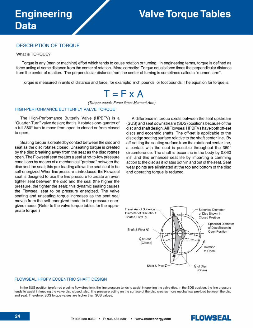
Valve Torque TablesEngineeringData

25T: 936-588-8380 • F: 936-588-8381 • www.craneenergy.com
Valve Torque Tables Engineering Data

26T: 936-588-8380 • F: 936-588-8381 • www.craneenergy.com
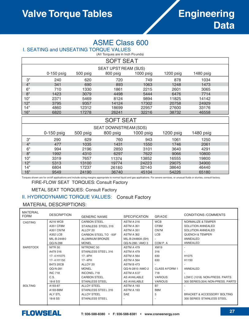
Valve Torque TablesEngineeringData
27T: 936-588-8380 • F: 936-588-8381 • www.craneenergy.com
Valve Torque Tables Engineering Data

28T: 936-588-8380 • F: 936-588-8381 • www.craneenergy.com
Body & ComponentsPressure/Temperature Ratings
EngineeringData
BODY RATINGThechartsbelowreflect thepressure/temperatureratingsforcarbonsteelandstainlesssteelvalves, inaccordancewithASMEB16.34.Thehydrostaticshelltestisperformedonthebodyat150%ofthecoldworkingpressure(C.W.P.isdefinedasthepressureratingbetween-20to100°F)andthehydrostaticseattestisperformedonthediscandseatat110%ofthecoldworkingpressure.
°FMaximum Non-ShockWorking Pressure-PSI
Carbon Steel (1) Carbon Steel (2) 316SSASME Class 150 300 600 150 300 600 150 300 600
HYDROSTATIC SHELL TEST
450 1125 2225 450 1125 2225 425 1100 2175
HYDROSTATIC SEAT TEST
315 815 1630 315 815 1630 305 800 1585
-20 - 32 285 740 1480 - - - 275 720 1440 32-100 285 740 1480 285 740 1480 275 720 1440
200 260 675 1350 260 675 1350 240 620 1240 300 230 655 1315 230 655 1315 215 560 1120 400 200 635 1270 200 635 1270 195 515 1030 500 170 600 1200 170 600 1200 170 480 955 600 140 550 1095 140 550 1095 140 450 905 650 125 535 1075 125 535 1075 125 445 890 700 110 535 1065 110 535 1065 110 430 865 750 95 505 1010 95 505 1010 95 425 845 800 80 410 825 80 410 825 80 415 830 850 65 405 810 900 50 395 7901000 20 365 725
(1)CEimpacttestedmaterialsandstandardnon-impacttestedmaterials.
(2)CEnon-impacttestedmaterials.
°CMaximum Non-Shock
Working Pressure-BarsCarbon Steel (1) Carbon Steel (2) 316SS
ASME Class 150 300 600 150 300 600 150 300 600
HYDROSTATIC SHELL TEST
30 77 153 30 77 153 29 75 150
HYDROSTATIC SEAT TEST
22 56.9 112.4 22 56.9 112.4 20.9 54.6 109.3
-29 to 0 19.6 51.1 102.1 - - - 19.0 49.6 99.3 0 to 38 19.6 51.1 102.1 19.6 51.1 102.1 19.0 49.6 99.3
50 19.2 50.1 100.2 19.2 50.1 100.2 18.4 48.1 96.3 100 17.7 46.4 92.8 17.7 46.4 92.8 16.2 42.2 84.4 150 15.8 45.2 90.5 15.8 45.2 90.5 14.8 38.5 77.0 200 14.0 43.8 87.6 14.0 43.8 87.6 13.7 35.7 71.3 250 12.1 41.7 83.4 12.1 41.7 83.4 12.1 33.4 66.8 300 10.2 38.7 77.5 10.2 38.7 77.5 10.2 31.6 63.3 350 8.4 37.0 73.9 8.4 37.0 73.9 8.4 30.4 60.8 400 6.5 34.5 69.0 6.5 34.5 69.0 6.5 29.1 58.2 425 5.6 28.8 57.5 5.6 28.8 57.5 5.6 28.7 57.3 450 4.7 28.1 56.2 500 2.8 26.8 53.7 525 1.9 25.8 51.6
(1)CEimpacttestedmaterialsandstandardnon-impacttestedmaterials.
(2)CEnon-impacttestedmaterials.
COMPONENTS RATINGThechartat right reflects themaximumtemperature ratingsforindividualcomponentsoftheFlowsealHPBFV.
Special care should be taken when specifying componentmaterialsforvalvesatelevatedtemperatures,especiallymetalseatvalves.
Consultfactoryifadditionalinformationisrequiredre-gardingthe suitability of components for specific pressure/tempera-tureapplications.
Description & Material Temperature°F °C
SeatSeal(SoftSeated)TFERTFEUHMWPE
-100to400-100to500-100to200
-73to204-73to260-73to93
SeatSeal(Fire-Flow)TFE/InconelRTFE/Inconel
-100to400-100to500
-73to204-73to260
SeatSeal(MetalSeats)Inconel718316StainlessSteel
-100to1150-100to1000
-73to621-73to538
SeatO-RingSilicone(StandardwithRTFE)Viton(StandardwithTFE)
-100to500-50to400
-73to260-46to204
StemPackingTFEGraphite
-100to500-100to1150
-73to260-73to621
Shaft17-4PHH115017-4PHH1150M316StainlessSteelK-Monel500Inconel718
-100to800-100to800-100to1150-100to1150-100to1150
-73to427-73to427-73to621-73to621-73to621
BearingsTFE/FiberglassCompositeRTFE/316StainlessSteelBronzeSteel316StainlessSteel
-100to500-100to500-100to750-100to1150-100to1000
-73to260-73to260-73to339-73to621-73to538
DiscTreatmentElectrolessNickelPlatingStelliteMalcomizing
-100to750-100to1150-100to900
-73to399-73to621-73to482

29T: 936-588-8380 • F: 936-588-8381 • www.craneenergy.com
Valve Mounting PadDimensions
Engineering Data
SIZE CLASS SERIES

30T: 936-588-8380 • F: 936-588-8381 • www.craneenergy.com
Installation InstructionsEngineeringData
31T: 936-588-8380 • F: 936-588-8381 • www.craneenergy.com
Installation Instructions Engineering Data
F G
BodyFlange Flange
B*A*
LUG BODYSTUDS & NUTS
LUG BODYHEX HEAD MACHINE BOLTS
BOLTING DIMENSIONS
Body
WAFER BODYSTUDS & NUTS
C D
Body
VALVESIZE
30"
36"
42"
48"
2" J 5/8-11 4 .940 4 .570 4 2.50 4 2.12 4 1.75 4 1.50 4 5.0021/2" J 5/8-11 4 .960 4 .680 4 2.62 4 2.38 4 2.00 4 1.62 4 5.25
3" J 5/ 8-11 4 1.139 4 .725 4 3.00 4 3.00 4 1.88 4 1.62 4 6.004" J 5/ 8-11 8 1.071 8 .745 8 3.00 8 3.00 8 2.00 8 1.62 8 6.005" J 3/4-10 8 1.220 8 .790 8 3.12 8 2.62 8 2.25 8 1.75 8 6.006" J 3/ 4-10 8 1.401 8 .839 8 3.50 8 2.75 8 2.38 8 1.75 8 6.508" J 3/ 4-10 8 1.492 8 .948 8 3.75 8 3.00 8 2.50 8 2.00 8 6.50
10" J 7/ 8-9 12 1.752 12 1.000 12 4.50 12 3.25 12 2.62 12 2.38 12 7.5012" J 7/ 8-9 12 2.147 12 1.025 12 4.50 12 3.25 12 3.38 12 2.25 12 8.0014" J 1-8 12 2.330 12 1.210 12 5.00 12 3.75 12 3.62 12 2.62 12 9.0016" J 1-8 16 2.648 16 1.270 16 5.25 16 4.00 16 4.00 16 2.62 16 10.0018" J 11/ 8-8 16 2.723 16 1.645 16 5.50 16 4.50 16 4.25 16 3.12 16 10.50
J 1 1/ 8-8 16 3.396 20 1.434 16 6.25 20 4.50 16 5.12 20 3.19 16 11.00J 1 1/ 8-8 4** 2.325 – – 4** 5.25 – – 4** 4.06 – – 8** 5.25J 1 1/ 4-8 20 3.690 20 2.250 20 6.75 20 5.25 20 5.50 20 4.12 20 12.50H 11/ 4-8 24 3.471 24 3.159 24 7.75 24 7.50 24 6.47 24 6.15 24 15.25H 11/ 4-8 4** 1.908 4** 1.592 4** 6.00 4** 5.75 4** 4.91 4** 4.59 8** 6.00H 11/ 2-8 28 3.760 28 3.740 28 9.00 28 9.00 28 7.19 28 7.19 28 18.25H 11/ 2-8 4** 1.760 4** 1.740 4** 6.75 4** 6.75 4** 5.25 4** 5.25 8** 6.75H 11/ 2-8 32 4.160 32 4.090 32 9.75 32 9.50 32 6.62 32 4.25 32 19.25H 11/ 2-8 4** 1.782 4** 1.718 4** 7.25 4** 7.25 4** 4.25 4** 4.25 8** 7.25H 11/ 2-8 40 5.520 40 4.850 40 11.75 40 11.00 40 9.83 40 9.16 40 21.00H 11/ 2-8 4** 2.815 4** 2.190 4** 7.75 4** 7.75 4** 7.12 4** 6.50 8** 7.75
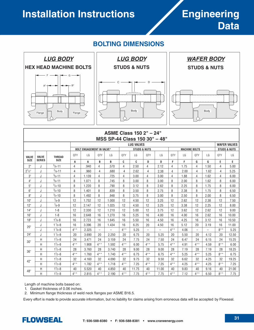
BOLT ENGAGEMENT IN VALVE* STUDS & NUTS MACHINE BOLTS STUDS & NUTS
ASME Class 150 2" – 24"MSS SP-44 Class 150 30" – 48"
LUG VALVES WAFER VALVES
VALVESERIES
THREADSIZE
24"
20"
A A B B C C D D F F G G E E
QTY LG QTY LG QTY LG QTY LG QTY LG QTY LG QTY LG
Every effort is made to provide accurate information, but no liability for claims arising from erroneous data will be accepted by Flowseal.
Length of machine bolts based on:1. Gasket thickness of 0.06 inches.2. Minimum flange thickness of weld neck flanges per ASME B16.5.
32T: 936-588-8380 • F: 936-588-8381 • www.craneenergy.com
Installation InstructionsEngineeringData
2" J 5/8-11 8 .940 8 .570 8 2.25 8 2.62 8 1.50 8 2.00 8 5.2521/2" J 5/8-11 8 .970 8 .670 8 2.75 8 3.00 8 1.75 8 2.00 8 5.75
3" J 3 4-10 8 1.034 8 .826 8 3.00 8 3.00 8 2.12 8 .75 8 6.004" J 3 4-10 8 1.196 8 .870 8 3.50 8 3.25 8 2.50 8 2.00 8 6.505" J 3/4-10 8 1.220 8 .790 8 5.25 8 3.62 8 2.25 8 2.75 8 7.006" J 3 4-10 12 1.301 12 .929 12 3.75 12 3.50 12 2.75 12 2.25 12 7.008" J 7 8-9 12 1.702 12 1.128 12 4.50 12 4.00 12 3.25 12 2.75 12 8.25
J 1-8 16 1.867 16 1.300 16 5.00 16 4.50 16 3.25 16 3.12 14 9.25J 1-8 – – – – – – – – – – – – 4** 5.00J 1 1 8-8 16 2.057 16 1.475 16 5.50 16 5.00 16 4.00 16 3.38 12 10.00J 1 1 8-8 – – – – – – – – – – – – 8** 5.25H 11 8-8 16 2.442 16 2.118 16 6.00 16 5.75 16 4.62 16 4.25 16 11.50H 11 8-8 4** 1.608 4** 1.267 4** 5.25 4** 4.75 4** 3.75 4** 3.44 8** 5.25H 11 4-8 16 2.562 16 2.628 16 6.50 16 6.50 16 4.88 16 4.88 16 13.00H 11 4-8 4** 1.538 4** 1.588 4** 5.25 4** 5.25 4** 3.88 4** 4.25 8** 5.25H 11 4-8 20 2.870 20 2.890 20 7.00 20 7.00 20 5.25 20 5.25 20 14.00H 11 4-8 4** 1.657 4** 1.437 4** 5.50 4** 5.50 4** 4.00 4** 3.88 8** 5.50H 11 4-8 20 3.184 20 3.006 20 7.50 20 7.25 20 5.69 20 5.69 20 14.50H 11 4-8 4** 1.681 4** 1.750 4** 5.75 4** 5.50 4** 4.19 4** 4.00 8** 5.75H 11 2-8 20 3.560 20 3.510 20 8.25 20 8.25 20 6.31 20 6.25 20 16.50H 11 2-8 4** 1.800 4** 1.750 4** 6.25 4** 6.25 4** 4.56 4** 4.50 8** 6.25H 13 4-8 24 4.331 24 4.429 24 10.25 24 10.50 24 7.88 24 7.88 24 20.50H 13 4-8 4** 2.039 4** 2.071 4** 8.00 4** 8.00 4** 5.44 4** 5.47 8** 8.00
A A B B C C D D F F G G E E
VALVESIZE A A B B C C D D F F G G E E
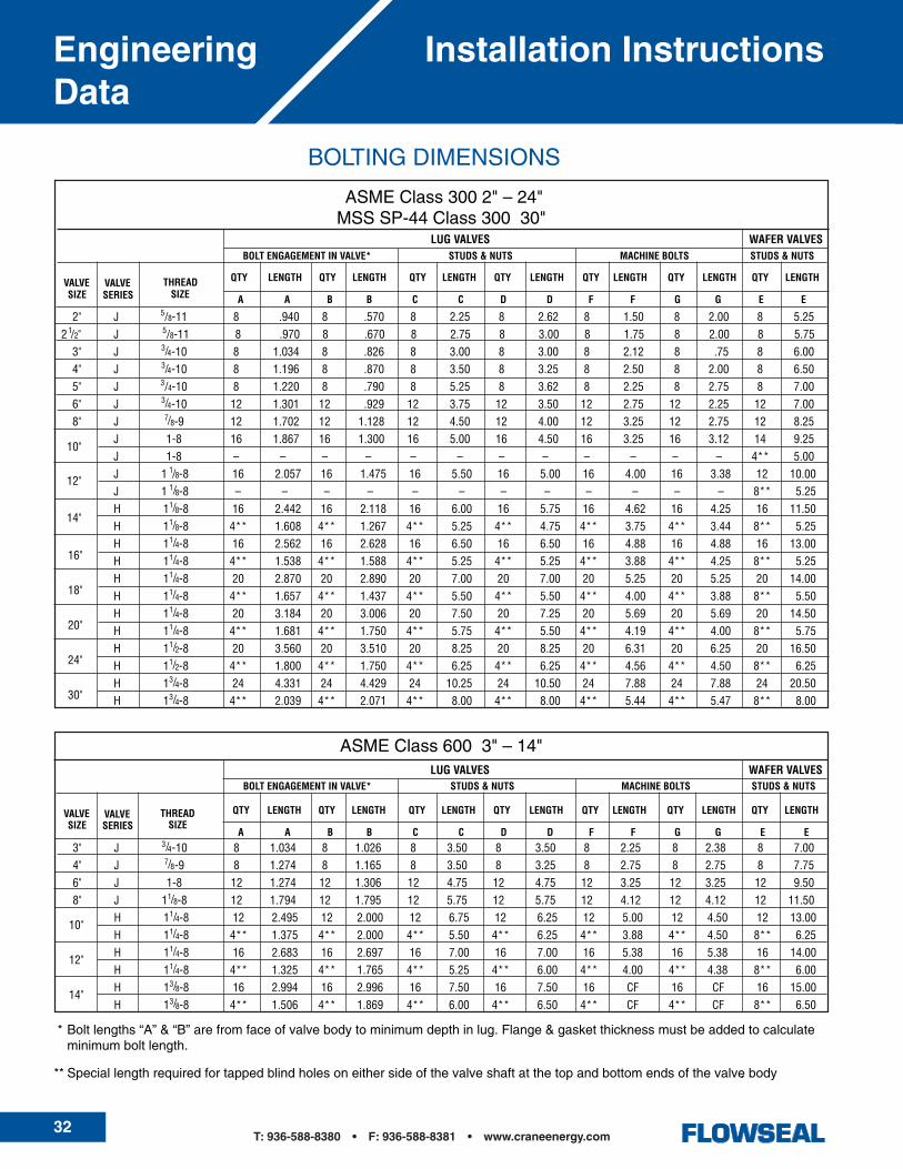
BOLT ENGAGEMENT IN VALVE* STUDS & NUTS MACHINE BOLTS STUDS & NUTS
LUG VALVES WAFER VALVES
VALVESERIES
QTY LENGTH QTY LENGTH QTY LENGTH QTY LENGTH QTY LENGTH QTY LENGTH QTY LENGTH
14"
16"
18"
20"
24"
30"
12"
10"
THREADSIZE
3" J 3 4-10 8 1.034 8 1.026 8 3.50 8 3.50 8 2.25 8 2.38 8 7.004" J 7 8-9 8 1.274 8 1.165 8 3.50 8 3.25 8 2.75 8 2.75 8 7.756" J 1-8 12 1.274 12 1.306 12 4.75 12 4.75 12 3.25 12 3.25 12 9.508" J 11 8-8 12 1.794 12 1.795 12 5.75 12 5.75 12 4.12 12 4.12 12 11.50
H 11 4-8 12 2.495 12 2.000 12 6.75 12 6.25 12 5.00 12 4.50 12 13.00H 11 4-8 4** 1.375 4** 2.000 4** 5.50 4** 6.25 4** 3.88 4** 4.50 8** 6.25H 11 4-8 16 2.683 16 2.697 16 7.00 16 7.00 16 5.38 16 5.38 16 14.00H 11 4-8 4** 1.325 4** 1.765 4** 5.25 4** 6.00 4** 4.00 4** 4.38 8** 6.00H 13 8-8 16 2.994 16 2.996 16 7.50 16 7.50 16 CF 16 CF 16 15.00H 13 8-8 4** 1.506 4** 1.869 4** 6.00 4** 6.50 4** CF 4** CF 8** 6.50
10"
12"
14"
VALVESIZE
THREADSIZE
VALVESERIES
LUG VALVES WAFER VALVESBOLT ENGAGEMENT IN VALVE* STUDS & NUTS MACHINE BOLTS STUDS & NUTS
QTY LENGTH QTY LENGTH QTY LENGTH QTY LENGTH QTY LENGTH QTY LENGTH QTY LENGTH
//
//
/
//
///
/
//////
/
//
///////

33T: 936-588-8380 • F: 936-588-8381 • www.craneenergy.com
Installation Instructions Engineering Data
34T: 936-588-8380 • F: 936-588-8381 • www.craneenergy.com
Typical SpecificationsFlowseal
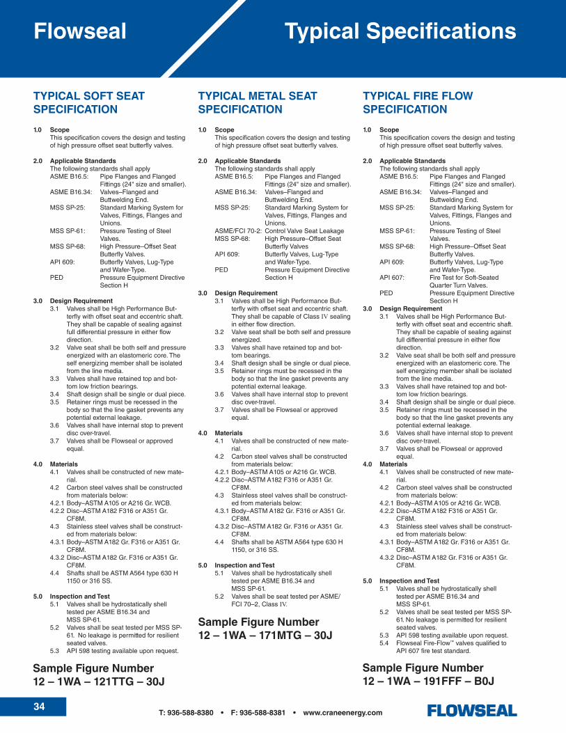
TYPICAL FIRE FLOW SPECIFICATION
1.0 Scope Thisspecificationcoversthedesignandtesting
ofhighpressureoffsetseatbutterflyvalves.
2.0 Applicable Standards Thefollowingstandardsshallapply ASMEB16.5: PipeFlangesandFlanged
Fittings(24"sizeandsmaller). ASMEB16.34: Valves–Flangedand
ButtweldingEnd. MSSSP-25: StandardMarkingSystemfor
Valves,Fittings,FlangesandUnions.
MSSSP-61: PressureTestingofSteelValves.
MSSSP-68: HighPressure–OffsetSeatButterflyValves.
API609: ButterflyValves,Lug-TypeandWafer-Type.
API607: FireTestforSoft-SeatedQuarterTurnValves.
PED PressureEquipmentDirectiveSectionH
3.0 Design Requirement 3.1 ValvesshallbeHighPerformanceBut-
terflywithoffsetseatandeccentricshaft.Theyshallbecapableofsealingagainstfulldifferentialpressureineitherflowdirection.
3.2 Valveseatshallbebothselfandpressureenergizedwithanelastomericcore.Theselfenergizingmembershallbeisolatedfromthelinemedia.
3.3 Valvesshallhaveretainedtopandbot-tomlowfrictionbearings.
3.4 Shaftdesignshallbesingleordualpiece. 3.5 Retainerringsmustberecessedinthe
bodysothatthelinegasketpreventsanypotentialexternalleakage.
3.6 Valvesshallhaveinternalstoptopreventdiscover-travel.
3.7 ValvesshallbeFlowsealorapprovedequal.
4.0 Materials 4.1 Valvesshallbeconstructedofnewmate-
rial. 4.2 Carbonsteelvalvesshallbeconstructed
frommaterialsbelow: 4.2.1Body–ASTMA105orA216Gr.WCB. 4.2.2Disc–ASTMA182F316orA351Gr.
CF8M. 4.3 Stainlesssteelvalvesshallbeconstruct-
edfrommaterialsbelow: 4.3.1Body–ASTMA182Gr.F316orA351Gr.
CF8M. 4.3.2Disc–ASTMA182Gr.F316orA351Gr.
CF8M.
5.0 Inspection and Test 5.1 Valvesshallbehydrostaticallyshell
testedperASMEB16.34and MSSSP-61. 5.2 ValvesshallbeseattestedperMSSSP-
61.Noleakageispermittedforresilientseatedvalves.
5.3 API598testingavailableuponrequest. 5.4 FlowsealFire-Flow™valvesqualifiedto
API607fireteststandard.
TYPICAL METAL SEAT SPECIFICATION
1.0 Scope Thisspecificationcoversthedesignandtesting
ofhighpressureoffsetseatbutterflyvalves.
2.0 Applicable Standards Thefollowingstandardsshallapply ASMEB16.5: PipeFlangesandFlanged
Fittings(24"sizeandsmaller). ASMEB16.34: Valves–Flangedand
ButtweldingEnd. MSSSP-25: StandardMarkingSystemfor
Valves,Fittings,FlangesandUnions.
ASME/FCI70-2: ControlValveSeatLeakage MSSSP-68: HighPressure–OffsetSeat
ButterflyValves API609: ButterflyValves,Lug-Type
andWafer-Type. PED PressureEquipmentDirective
SectionH
3.0 Design Requirement 3.1 ValvesshallbeHighPerformanceBut-
terflywithoffsetseatandeccentricshaft.TheyshallbecapableofClassIVsealingineitherflowdirection.
3.2 Valveseatshallbebothselfandpressureenergized.
3.3 Valvesshallhaveretainedtopandbot-tombearings.
3.4 Shaftdesignshallbesingleordualpiece. 3.5 Retainerringsmustberecessedinthe
bodysothatthelinegasketpreventsanypotentialexternalleakage.
3.6 Valvesshallhaveinternalstoptopreventdiscover-travel.
3.7 ValvesshallbeFlowsealorapprovedequal.
4.0 Materials 4.1 Valvesshallbeconstructedofnewmate-
rial. 4.2 Carbonsteelvalvesshallbeconstructed
frommaterialsbelow: 4.2.1Body–ASTMA105orA216Gr.WCB. 4.2.2Disc–ASTMA182F316orA351Gr.
CF8M. 4.3 Stainlesssteelvalvesshallbeconstruct-
edfrommaterialsbelow: 4.3.1Body–ASTMA182Gr.F316orA351Gr.
CF8M. 4.3.2Disc–ASTMA182Gr.F316orA351Gr.
CF8M. 4.4 ShaftsshallbeASTMA564type630H
1150,or316SS.
5.0 Inspection and Test 5.1 Valvesshallbehydrostaticallyshell
testedperASMEB16.34and MSSSP-61. 5.2 ValvesshallbeseattestedperASME/
FCI70–2,ClassIV.
TYPICAL SOFT SEAT SPECIFICATION
1.0 Scope Thisspecificationcoversthedesignandtesting
ofhighpressureoffsetseatbutterflyvalves.
2.0 Applicable Standards Thefollowingstandardsshallapply ASMEB16.5: PipeFlangesandFlanged
Fittings(24"sizeandsmaller). ASMEB16.34: Valves–Flangedand
ButtweldingEnd. MSSSP-25: StandardMarkingSystemfor
Valves,Fittings,FlangesandUnions.
MSSSP-61: PressureTestingofSteelValves.
MSSSP-68: HighPressure–OffsetSeatButterflyValves.
API609: ButterflyValves,Lug-TypeandWafer-Type.
PED PressureEquipmentDirectiveSectionH
3.0 Design Requirement 3.1 ValvesshallbeHighPerformanceBut-
terflywithoffsetseatandeccentricshaft.Theyshallbecapableofsealingagainstfulldifferentialpressureineitherflowdirection.
3.2 Valveseatshallbebothselfandpressureenergizedwithanelastomericcore.Theselfenergizingmembershallbeisolatedfromthelinemedia.
3.3 Valvesshallhaveretainedtopandbot-tomlowfrictionbearings.
3.4 Shaftdesignshallbesingleordualpiece. 3.5 Retainerringsmustberecessedinthe
bodysothatthelinegasketpreventsanypotentialexternalleakage.
3.6 Valvesshallhaveinternalstoptopreventdiscover-travel.
3.7 ValvesshallbeFlowsealorapprovedequal.
4.0 Materials 4.1 Valvesshallbeconstructedofnewmate-
rial. 4.2 Carbonsteelvalvesshallbeconstructed
frommaterialsbelow: 4.2.1Body–ASTMA105orA216Gr.WCB. 4.2.2Disc–ASTMA182F316orA351Gr.
CF8M. 4.3 Stainlesssteelvalvesshallbeconstruct-
edfrommaterialsbelow: 4.3.1Body–ASTMA182Gr.F316orA351Gr.
CF8M. 4.3.2Disc–ASTMA182Gr.F316orA351Gr.
CF8M. 4.4 ShaftsshallbeASTMA564type630H
1150or316SS.
5.0 Inspection and Test 5.1 Valvesshallbehydrostaticallyshell
testedperASMEB16.34and MSSSP-61. 5.2 ValvesshallbeseattestedperMSSSP-
61.Noleakageispermittedforresilientseatedvalves.
5.3 API598testingavailableuponrequest.
Sample Figure Number12 – 1WA – 121TTG – 30J
Sample Figure Number12 – 1WA – 191FFF – B0J
Sample Figure Number12 – 1WA – 171MTG – 30J

35T: 936-588-8380 • F: 936-588-8381 • www.craneenergy.com
Actuators Flowseal

Global Headquarters9200NewTrailsDrive,Suite200
TheWoodlands,Texas77381-5219Tel:281-298-5463Fax:281-298-1920
Sydney, Australia, Operations146–154DunhevedCircuitSt.Mary’s,N.S.W.2760
AustraliaTel:+61(2)96230234Fax:+61(2)96733870
www.craneenergy.com
CRANE®
CastSteel,BronzeandIronValves
JENKINS®
Bronze,IronandCastSteelValves
PACIFIC®
HighPressureandSevereServiceValvesQuarterTurnSevereServicePlugValves
ALOYCO®
CorrosionResistantGate,GlobeandCheckValves
NOZ-CHEK® & COMPAC-NOZ®
SevereService,Nozzle-TypeCheckValves
FLOWSEAL®
HighPerformanceButterflyValves
DUO-CHEK®
HighPerformanceWaferCheckValves
CENTER LINE®
ResilientSeatedButterflyandCheckValvesPneumaticandElectricActuators
UNI-CHEK®
SevereServiceCheckValves
A Crane Co. Company
WEDGEPLUG®
SevereService,Metal-SeatedPlugValves
Conroe, TX, Operations9860JohnsonRoad
Montgomery,TX77316Tel:936-588-8380Fax:936-588-8381
Dusseldorf, GmbH, OperationsCraneProcessFlowTechnology,GmbH
HeerdterLohweg63-71,D-40549Dusseldorf,GermanyTel:+4921159560
Fax:+492115956-111www.craneflow.com
Crane Energy Flow Solutions
Crane,CenterLine,Flowseal,Duo-Chek,Uni-Chek,Pacific,Jenkins,Noz-Chek,Compac-Noz,WedgeplugandAloycoaretrademarksofCraneCo.
©2008
www.cranevalve.com/aussie/aussie.htm
CV-501a0108