General Disclaimer One or more of the Following Statements ... · WBS = Work Breakdown Structure I....
12
General Disclaimer One or more of the Following Statements may affect this Document This document has been reproduced from the best copy furnished by the organizational source. It is being released in the interest of making available as much information as possible. This document may contain data, which exceeds the sheet parameters. It was furnished in this condition by the organizational source and is the best copy available. This document may contain tone-on-tone or color graphs, charts and/or pictures, which have been reproduced in black and white. This document is paginated as submitted by the original source. Portions of this document are not fully legible due to the historical nature of some of the material. However, it is the best reproduction available from the original submission. Produced by the NASA Center for Aerospace Information (CASI) https://ntrs.nasa.gov/search.jsp?R=20130012526 2019-03-27T18:21:33+00:00Z
Transcript of General Disclaimer One or more of the Following Statements ... · WBS = Work Breakdown Structure I....
General Disclaimer
One or more of the Following Statements may affect this Document
This document has been reproduced from the best copy furnished by the
organizational source. It is being released in the interest of making available as
much information as possible.
This document may contain data, which exceeds the sheet parameters. It was
furnished in this condition by the organizational source and is the best copy
available.
This document may contain tone-on-tone or color graphs, charts and/or pictures,
which have been reproduced in black and white.
This document is paginated as submitted by the original source.
Portions of this document are not fully legible due to the historical nature of some
of the material. However, it is the best reproduction available from the original
submission.
Produced by the NASA Center for Aerospace Information (CASI)
https://ntrs.nasa.gov/search.jsp?R=20130012526 2019-03-27T18:21:33+00:00Z

45th AIAA/ASMEJSAE/ASEE Joint Propulsion Conference
AJAA 2009-5344 2-5 August 2009, Denver, Colorado
TheFunctional Breakdown Structure (FBS) and Its Relationship to Life Cycle Cost
Bryan DeHoff4 SynGenics Corp. Delaware, Ohio, 43015
Daniel J. H. Levack2 Pratt & Whitney Rocketdyne, Canoga Park, Calfornia, 91309
and Russel E. Rhodes3
NASA, Kennedy Space Center, Florida, 32899
The Functional Breakdown Structure (FBS) is a structured, modular breakdown of every function that must be addressed to perform a generic mission. It is also usable for any subset of the mission. Unlike a Work Breakdown Structure (WBS), the FBS is a function-oriented tree, not a product-oriented tree. The FBS details not products, but operations or activities that should be performed. The FBS is not tied to any particular architectural implementation because it is a listing of the needed functions, not the elements, of the architecture. The FBS for Space Transportation Systems provides a universal hierarchy of required functions, which include ground and space operations as well as infrastructure - it provides total visibility of the entire mission. By approaching the systems engineering problem from the functional view, instead of the element or hardware view, the SPST has created an exhaustive list of potential requirements which the architecture designers can use to evaluate the completeness of their designs. This is a new approach that wifi provide full accountability of all functions required to perform the planned mission. It serves as a giant check list to be sure that no functions are omitted, especially in the early architectural design phase.
A significant characteristic of a FBS is that if architecture options are compared using this approach, then any missing or redundant elements of each option will be ' identified. Consequently, valid Life Cycle Costs (LCC) comparisons can be made. For example, one architecture option might not need a particular function while another option does. One option may have individual elements to perform each of three functions while another option needs only one element to perform the three functions.
Once an architecture has been selected, the FBS will serve as a guide in development of the work breakdown structure, provide visibility of those technologies that need to be further developed to perform required functions, and help identify the personnel skills required to develop and operate the architecture. It also wifi allow the systems engineering activities to totally integrate each discipline to the maximum extent possible and optimize at the total system level, thus avoiding optimizing at the element level (stove-piping). In addition, it furnishes a framework that wifi help prevent over or under specifying requirements because all functions are identified and all elements are aligned to functions.
'Principal Aerospace Engineer, SynGenics Corp, 5190 Olentangy, River Road, Delaware, OH 43015, AIAA Senior Member. 2 Program Manager, Advanced Programs, P.O. Box 7922 / MS RFB19, A1[AA Member.
AST, Technical Management, Engineering Directorate Design & Development Eng Div Sys Engineering & Integration Br, Kennedy Space Center, FloridalNE-D2, AIAA Senior Member..
American Institute of Aeronautics and Astronautics

45th AJAA!ASMEJSAEJASEE Joint Propulsion Conference AIAA 2009-5344 2-5 August 2009, Denver, Colorado
Nomenclature
CONSIZ = Configuration Sizing (A LaRC vehicle sizing code) DDT&E = Design, Development, Test and Evaluation DoD = Department of Defense ESR&T = Exploration System Research and Technology ETO = Earth-to-Orbit FBS = Functional Breakdown Structure HDBK = Handbook KSC = NASA Kennedy Space Center Li = Earth-Moon Lagrange point LaRC = NASA Langley Research Center LCC = Life Cycle Cost MIL STD = Military Standard NASA = National Aeronautics and Space Administration NGLT = Next-Generation Launch Technologies SPST = Space Propulsion Synergy Team WBS = Work Breakdown Structure
I. Introduction
THE evolution of rockets is an evolution of complexity, and increasingly complex systems present many (squared) opportunities for errors, omissions, or bad assumptions. Decomposing complex systems is the science
of Systems Engineering; a science which matured alongside the complex systems of the Apollo era. However, like most true scientific knowledge, the origins of the science of Systems Engineering can really be found in the thinking and actions of those early engineers and logisticians from the 1600's era of exploration. As they studied the problems before them, the successes in exploration added continents to the map, identified the currents in the ocean, and solved the problems of navigation. Today, the field of Systems Engineering allows the engineer to deal with increasing complexity using a disciplined analysis of the problem to be solved or the goal to be achieved.
The problem of this paper is the problem of exploration, which has similar aspects if one is venturing from Europe across the seas in the 1600's, exploring the polar regions in the late 1800's or exploring space in the here and now. Each of these exploration ages has dealt with the same system issues - how to predict the equipment and supply requirements for the unforeseen experiences that will be encountered by the explorers. Civilian and military applications of space transportation have been pursued for 50 years and there has been, and still is, a need for safe, dependable and affordable space transportation systems, both in the regimes of Earth-to-Orbit (ETO) and in-space. Safety, dependability, and affordability must be met to enable sustainable space exploration or conunercial space development to occur. In the recent past, several approaches which focused on performance while trying to satisfy these needs have been explored. Fully expendable and partially reusable space transportation systems have been developed and put in operation. However, all current space transportations systems have major shortfalls. More importantly, the design process tools have major shortfalls for focusing on the goals of safety, dependability, and affordability.
IL The Current Problem
This Nation's ability to provide the development and operation of safe, dependable, affordable and sustainable space transportation systems is still not being achieved. Access to space is technically achievable, but presently very expensive.
The life cycle cost (LCC) of the entire space transportation system necessary to enable an exploration architecture consists of the development and acquisition costs and the operations and disposal costs. For space transportation systems that will be in place for a long time, typical for current space systems, the operations and disposal costs will dominate the LCC. New programs must be "sustainable", i.e., they must be within their specific budget and within their yearly budget caps both during procurement and throughout their long operating life. For this to be achievable, operability must be designed into the architectures and elements from the very beginning. Failure to achieve the budgeted transportation costs will squeeze the exploration budget and has the potential to severely impact the sustainability of the entire program.
During conceptual defmition and DDT&E phases, the only major objective (system attribute) controlled in past and present programs by a structured engineering management process has been performance closure by managing
American Institute of Aeronautics and Astronautics

45th AIAA/ASME/SAEJASEE Joint Propulsion Conference AIAA 2009-5344 2-5 August 2009, Denver, Colorado
flight systems weight. The present cost estimating process bases cost on flight system dry weight and performs all trade studies optimizing each single flight system function, with no effort to address integrating the total systems considering all desired attributes. As an example, objectives were set for LCC for the Shuttle, but no engineering management processes were exercised to provide control (only the DDT&E cost was tracked). Because the objective was not treated as a requirement, but only as a goal, it was not achieved.
The SaturnlApollo lunar exploration program was terminated early because the recurring transportation cost was not sustainable while supporting the exploration efforts. The reusable Shuttle transportation system was developed to replace the Saturn launch vehicle in an effort to greatly reduce the recurring cost of transportation. Even though the recurring cost of space transportation systems operation was reduced approximately 75 to 80 percent', the reduction was not sufficient and did not approach the target goal.
A major lesson identified from the Saturn/Apollo and Shuttle experience is that much improved, innovative processes must be developed and rigorously applied to effectively control LCC. Any future space transportation system LCC must be controlled throughout the entire design concept phase, DDT&E phase, and the operations phase to provide a sustainable space exploration program. Since a major part of LCC for a space transportation system is the recurring or operational phase cost, this cost must be defined in the design concept phase and rigorously controlled throughout that and subsequent phases.
The primary lesson learned from studying the past programs is that if the industry always does what it has done before, then the industry will always get the same result. Therefore, achievement of major reductions in LCC will not be accomplished using the same existing processes and approaches.
Although many specific problems have been identified in the approaches and tools used in the past to achieve affordable LCC, this paper will concentrate only on two past problems:
1. architecture options have not been compared on the same level in early concept studies resulting in the inability to choose architectures based on believable LCC comparisons, and not all needed mission functions have been fully identified at program initiation;
2. there has been much less functional integration across elements than would be desirable for lowering LCC. Part of the problem is the lack of good approaches and good tools to identify and assess all of the needed
functions of a specific mission.
A. Architecture Comparisons and Mission Function Definition The operations and disposal costs are determined, often without specific planning, during the system architecture
definition and the individual element developments. It has been estimated that 80 percent of the design decisions are irreversibly made in the system architecture definition and the individual element development design phases
It is very difficult during architecture defmition to balance and minimize, or even compare, the overall LCC, including both development and acquisition costs and operations costs. This is primarily due to the lack of full defmition of all the necessary functions of the potential architectine options. Different options have different levels of definition but still must be compared. And often not all of the supporting elements necessary for each architecture are identified at all. It is also very difficult during element developments, primarily due to schedule and budget pressures, to maintain the design discipline to ensure that operations costs will not escalate due to design decisions addressing immediate design, weight, performance, or development problems. The emphasis in design is to get the job done (i.e., achieve weight and performance) within the schedule and hopefully within the budget. When problems must be solved there is seldom the budget or schedule available to properly consider the operations cost impacts of the design options examined. Consequently, the future operations and disposal costs escalate to improve the currently incurred development costs.
There is a need to assure that concepts are equally defined, described, and complete to allow fair comparisons. One of the major problems in these comparisons is the lack of credible operations models. Each concept compared must be responsive to all performance, safety, and cost needs or be brought up to compliance before being compared.
B. Functional Integration Across Elements It is important to establish a structured process to control recurring costs across multiple levels and elements of a
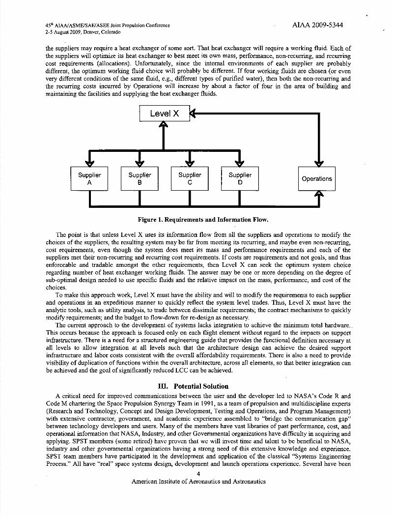
program. Figure 1 shows that at any particular level in the program there are elements being designed for that level. Each of the elements has requirements for mass, performance, and, non-recurring, and recurring cost. Note carefully the flow of impacts shown in the figure. Level X can impose requirements on Suppliers A, B C, and D and on the Operations. And they can all give information on requirement compliance back to Level X. However, Operations and each of the suppliers have no ability to modify requirements to each other. Nonetheless, many of the decisions made by Suppliers A, B, C, and D directly impact and change the requirements on Operations. For example, each of
American Institute of Aeronautics and Astronautics
45th AIAAJASMEJSAEJASEE Joint Pmpulsion Conference AIAA 2009-5344 2-5 August 2009, Denver, Colorado
the suppliers may require a heat exchanger of some sort. That heat exchanger will require a working fluid. Each of the suppliers will optimize its heat exchanger to best meet its own mass, performance, non-recurring, and recurring cost requirements (allocations). Unfortunately, since the internal environments of each supplier are probably different, the optimum working fluid choice will probably be different. If four working fluids are chosen (or even very different conditions of the same fluid, e.g., different types of purified water), then both the non-recurring and the recurring costs incurred by Operations will increase by about a factor of four in the area of building and maintaining the facilities and supplying the heat exchanger fluids.
Figure 1. Requirements and Information Flow.
The point is that unless Level X uses its information flow from all the suppliers and operations to modify the choices of the suppliers, the resulting system may be far from meeting its recurring, and maybe even non-recurring, cost requirements, even though the system does meet its mass and performance requirements and each of the suppliers met their non-recurring and recurring cost requirements. If costs are requirements and not goals, and thus enforceable and tradable amongst the other requirements, then Level X can seek the optimum system choice regarding number of heat exchanger working fluids. The answer may be one or more depending on the degree of sub-optimal design needed to use specific fluids and the relative impact on the mass, performance, and cost of the choices.
To make this approach work, Level X must have the ability and will to modify the requirements to each supplier and operations in an expeditious manner to quickly reflect the system level trades. Thus, Level X must have the analytic tools, such as utility analysis, to trade between dissimilar requirements; the contract mechanisms to quickly modify requirements; and the budget to flow-down for re-design as necessary.
The current approach to the development of systems lacks integration to achieve the minimum total hardware.. This occurs because the approach is focused only on each flight element without regard to the impacts on support infrastructure. There is a need for a structured engineering guide that provides the functional definition necessary at all levels to allow integration at all levels such that the architecture design can achieve the desired support infrastructure and labor costs consistent with the overall affordability requirements. There is also a need to provide visibility of duplication of functions within the overall architecture, across all elements, so that better integration can be achieved and the goal of significantly reduced LCC can be achieved.
Ill. Potential Solution A critical need for improved communications between the user and the developer led to NASA's Code R and
Code M chartering the Space Propulsion Synergy Team in 1991, as a team of propulsion and multidiscipline experts (Research and Technology, Concept and Design Development, Testing and Operations, and Program Management) with extensive contractor, government, and academic experience assembled to "bridge the communication gap" between technology developers and users. Many of the members have vast libraries of past performance, cost, and operational information that NASA, Industry, and other Governmental organizations have difficulty in acquiring and applying. SPST members (some retired) have proven that we will invest time and talent to be beneficial to NASA, industry and other governmental organizations having a strong need of this extensive knowledge and experience. SPST team members have participated in the development and application of the classical "Systems Engineering Process." All have "real" space systems design, development and launch operations experience. Several have been
American Institute of Aeronautics and Astronautics
45th AIAAIASMEJSAEJASEE Joint Propulsion Conference AIAA 2009-5344 2-5 August 2009, Denver, Colorado
through the entire systems acquisition process, some more than once. The SPST concluded its first task should use its member's diversified expertise toward developing new "Management Decision Making Tools" or innovative approaches and processes in the architectural design, development, and operations of space transportation systems to satisfy the challenging requirements of the transportation operators and the payload customers while providing a bridge to commercializing space travel.
The SPST has developed a new approach for formulating requirements that will provide full accountability of all functions required to perform the planned missions. The approach is to develop a top-level functional breakdown structure (FBS) with modular subsets that may be utilized as a basis for defining the desired "functional requirements" in any system.
The FBS developed by the SPST evolved out of efforts started at NASA. In an effort to determine where in the design sequence opportunities are being lost to perform early systems integration, the analysis team reviewed typical weight statements used by such popular weights and sizing programs as CONSIZ. The team found relatively detailed functional breakdowns for engine systems and primary structures. Not found was an equivalent level of definition and identification for the other design disciplines, such as thermal management, communications, guidance and flight control, and power management. While much of this functional hardware may have been "covered" at higher indentured levels in the weight breakdown structures, the generic design functions are not being treated homogeneously during the design process for attributes other than weight; such as total subsystem count, relative order of magnitude of ground interfaces, number of separate working fluids, propellants and gases, and so forth. Thus, the conceptual design process is likely to be left blind to these key design characteristics. Further, in some weight breakdown structures being used, functional hardware required for the integration of flight elements and stages was going unidentified (such as ordnance subsystems, attach hardware, and thermal protection). For the operations specialist participating in concept reviews or for the operations modeler, these non-homogeneously defined system weight breakdown structures were the best available.
The question was raised as to whether one could generically define vehicle and flight element design functions homogeneously across all the design disciplines, similar to the way the ground functions were generically defined. This might provide a pathway to reform traditional weight statements into more uniformly defined system statements that would inherently possess more conceptual-level definition and insight than just mass, volume, and center of gravity. A cataloging of generic ground functions had already been created and refined several times (see Section 3 and the FBS in Appendix A of Reference 2). It seemed reasonable to perform a similar, start-from-scratch exercise for generic flight system definition.
Thus, a Functional Breakdown Structure (FBS) effort was organized in the Systems Engineering Office at KSC in 2003 in support of NASA's Next-Generation Launch Technologies (NGLT) program. By 2004, the government, industry, and academia Space Propulsion Synergy Team began actual development work on a FBS. During the formative stages of the work, the FBS was significantly broadened in scope to support advanced technology life cycle analysis for NASA's Exploration Systems Research and Technology (ESR&T) effort as part of the Vision for Space Exploration.
The SPST Functional Breakdown Structure (FBS) has evolved from over 10 years of analyzing the functional requirements of space transportation systems, including Earth-to-Orbit, and in-space oriented systems. Based on that experience, the SPST began to see a repeatable pattern of system developments which excluded major requirements in the early planning, for a variety of reasons. The result of excluding requirements in the early planning, and attempting to address them later in the system design program has always been significant growth in total life cycle or system acquisition cost, decreases in system performance, increased development schedule, or all three. Previous products of the SPST efforts include the "A Guide for the Design of Highly Reusable Space Transportation 3 , the "SPST Collaborative Prioritization of Advanced RLV Technologies" 4, and the Space Shuttle Shortfalls Assessment5.
IV. The Functional Breakdown Structure as a Systems Engineering Tool The SPST FBS is a structured, modular breakdown of every function that must be addressed to perform a generic
mission, or any subset of that mission. It is an indentured listing of the system's functions for an architecture from the very top level down to where the last function identified cannot be further decomposed uniformly The FBS leads an early Program Team into the requirements necessary to accomplish the perceived and known missions that the future system must be capable of accomplishing.
The Space Propulsion Synergy Team has developed a generic FBS for the problem of future space exploration and transportation system. While typical Work Breakdown Structures (WBS), as defined in both DoD and industry Project Management literature, strive to describe all the elements of a systems, the SPST FBS strives to describe all
American Institute of Aeronautics and Astronautics

45th AIAAJASMEJSAEJASEE Joint Pmpulsion Conference ATAA 2009-5344 2-5 August 2009, Denver, Colorado
the things a space exploration system or space transportation system would have to be capable of doing. The FBS emphasizes the "what's" that an architecture must do, while the WBS emphasizes the "how's" that the architecture uses to achieve the "what's". By approaching the systems engineering problem from the functional view, instead of the element or hardware view, the SPST has created an exhaustive list of potential functions that the various architecture designers can use to evaluate the completeness of their design concepts.
If one considers the typical aspects of a systems engineering process, such as the "Vee" diagram of Buede 6, the systems engineering process is only halfway complete if it doesn't address ways to verify and test the design's ability to achieve the requirements. If affordability or life cycle cost targets are treated as requirements, then the Systems Engineering process needs to include verification of these requirements as well. By distilling the basic problem down into the individual capabilities required, architectural details are not brought into the debate until the appropriate time. Examples abound in everyday life of architectural differences in accomplishing the same function as one trip through the parking lot will demonstrate. Every five passenger car in the lot meets the same basic functional requirements, with greatly varying levels of Life Cycle Cost. When the U.S. astronauts first saw the Soyuz hardware and launch structures during the Apollo/Soyuz Joint Program in the early 1970's, they commented on the differences of the hardware between the two systems; "The Russians entered the project with equipment decidedly backward compared with the American hardware and systems."7
V. The Functional Breakdown Structure Applied to the Space Exploration Problem A FBS differs in intent from a WBS. For those Systems Engineers and Program Managers familiar with DoD
guidance, the SPST FBS will not fit the expected concept of a Program WBS. According to MIL Handbook 881, formerly MIL STD 88 1B, the guidebook on Work Breakdown Structures,
"The Program WBS provides a framework for specifying the objectives of the program. It defmes the program in terms of hierarchically related product-oriented elements. Each element provides logical summary points for assessing technical accomplishments and for measuring cost and schedule performance.... The work breakdown structures summarize data for successive levels of management and provide the appropriate information on the projected, actual, and current status of the elements for which they are responsible. The WBS keeps the program's status constantly visible so that the program manager, in cooperation with the contractor, can identify and implement changes necessary to assure desired performance."8
Mil HDBK 881 defines a WBS as "A product-oriented family tree composed of hardware, software, services, data, and facilities. The family tree results from systems engineering efforts during the acquisition of a defense materiel item."7
The SPST FBS is not a product oriented tree, but a function oriented tree. From Level 1 to the lowest levels, the FBS details not products, but operations, activities, and functions that must be performed. The SPST FBS precedes the development, or conceptualization of the Space Exploration Architecture, just as the sample WBS templates in the Appendices of MIL HDBK 881 precede the system concept exploration phase for a defense material item. In this respect, the functions identified in the FBS must be evaluated by the Space Exploration system engineer and a judgment must be made as to the applicability of the function to the current architecture mission requirements.
The SPST FBS provides a universal hierarchy of space transportation operational functions which include ground and space operations as well as infrastructure. It provides a structured, indentured breakdown for use in providing guidance to architectural concept design developers and visibility and definition in accounting for all functions; i.e., a giant check list to be sure that no functions are omitted especially in the early architectural design phases.
In place of starting with the hardware system/subsystemicomponent Weight or Work Breakdown Structure (WBS), the FBS approach accomplishes several important objectives. It ensures that the operational requirements (both ground and flight) are addressed in the design conceptual process, providing accountability for the total flight/ground system acquisition and operation and will result in lower manpower (labor) and material cost; therefore, much lower Life Cycle Cost with improved safety and dependability.
Additionally, the SPST FBS furnishes inputs for analysis of any concept and provides a systematic source for determining and documenting the requirements and life cycle cost necessary to achieve the Program/Project goals and objectives. When used correctly, the FBS furnishes a framework for defining requirements which will preclude over or under specifying the requirements.
As has been discussed, since FBS's and WBS's are not the same, a single item in a WBS may address multiple items in a FBS while multiple items in a WBS may be needed to address a single item in a FBS.
American Institute of Aeronautics and Astronautics
45th AIAAJASMEJSAEJASEE Joint Propulsion Conference AIAA 2009-5344 2-5 August 2009, Denver, Colorado
Because a traditional WBS is an indentured list of systems/sub-systems/parts, by its nature it needs to reflect a technical solution to reach deep levels of indenture. Consequently, WBS's are necessary and ideal for weight management and control and performance comparisons, managing contractors and sub-contractors, and some types of non-recurring cost comparisons.
On the other hand, because a FBS is an indentured listing of the system's functions for an architecture from the very top level down to where the last function identified cannot be further decomposed, it is especially useful for concept definition and trade studies. The FBS is ideal for requirements defrnition because it isolates the functions from the technical solutions/subsystems/parts. The FBS allows imposition of true functional requirements versus using constraints due to particular technical solutions, it helps to keep requirements at the same level throughout the architecture. The FBS is ideal as a filter for concept comparison because it facilitates the use of two criteria: it checks concepts a, b, c, etc. against the requirements defined at given function levels; and it checks-off functions implemented by the concept. Fair LCC comparisons require that concepts only be compared when they satisfy both of these criteria. Concepts that do not satisfy both of these criteria are leaving out some systems/subsystems/parts.
VI. The Use of the FBS Developed by the SPST This SPST FBS workbook has been developed with tabs established at different levels of the Space
Transportation System breakdown structure to allow the ease of use to matrix this FBS with other intended functions being analyzed. The FBS is established at the 3rd, 4th, and 5th composite levels and at the 6th level for the generic flight element. Also the FBS is established with tabs for the "Generic Ground Node" at the 3rd, 4th, and 5th levels. This 'Generic Ground Node" is intended to represent the Earth, Moon, and Mars surfaces as well as space operations nodes that conduct ground-like functions that might be in Mars orbit, Moon orbit, Li, Earth orbit, etc.
In place of starting with the hardware systemlsubsystemlcomponent Weight or Work Breakdown Structure (WBS), the SPST proposes using this FBS. This will assure that the early design phase will address all of the functions by using the FBS as a "giant check list". The FBS allows accommodating many discipline functions into a uniform, comprehensive, and fully integrated solution. This will enable the minimizing of total part count, ground and vehicle interfaces, and make visible the accumulation of operations labor (both direct and the large indirect infrastructure support).
Space operations experience shows that recurring cost are driven by labor costs. Thus, the SPST Functional Requirements Sub-team has devoted time and energy to the developing of this FBS during the past decade. Lesson learned: The SPST has shown that labor is the largest part of the LCC for the Space Shuttle Operational Program.
The FBS will provide an excellent guide to determine personnel discipline skills required to accomplish the new space initiative DDT&E and operations.
The FBS will serve as a guide to perform an assessment of existing government and industry facilities during the DDT&E phase and the operations phase of the any space exploration initiative. It will also help determine the surplus or shortfalls to allow determining the investment needed. This is also needed to determine the LCC for the system investors or government sponsors.
The FBS will serve to evaluate the planned WBS's being considered to manage the Space Exploration Initiative development and for determining the "technology shortfalls" in the planning process for the Space Transportation System elements as well as for different scenarios under consideration.
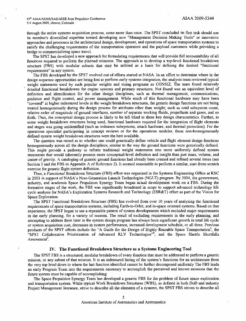
The space transportation system needed for the exploration mission can be addressed with the FBS already significantly developed by the SPST. Figure 2 shows a screen shot of one of the tabs in the SPST developed FBS.
As more clearly shown in Figure 3, the exploration system is broken into three categories: vehicle functions, element integrations functions, and ground infrastructure functions. "Ground" is used generically to apply anywhere infrastructure needs are met. The category applies to infrastructure on the earth, or on a non-earth body, or even in space - basically anywhere a needed service function is to be performed.
Notice that the FBS structure is very general and modular. Each second level function can be used as many times as needed by a particular architectural approach. The FBS can be applied to the space transportation needs of a low earth orbit launch system, of an in-space orbit transfer system, of a Mars exploration mission, or of an entire exploration architecture.
American Institute of Aeronautics and Astronautics

F H
° 55 Tenenc Funcnon Descrrprron FBS5rhitrh
• 1 0 Sujstern Architectural Concept Narno • 11 Vehicle Element )e 9. Boosrem. Orbiter, Pagload element, repeat as needed For elermrwmtrsj • I II AirFrame Structure Mechanisms
I 2 Propulsion lii Power Management
• I .4 Thermal Management • 1 I 5 Guidance, Navigation and Control
i.t.t Communications. Control and Health Management 1.17 LiFe Support 1.18 Environmental and Salerg Management
1 2 Vehicle Elernemrto Integration (Booster, Orbirer. ILl element. Planet or Moon DecenrlAsr 1.2 I Element ro element nrructwral arrachmenr 1.22 Element to element commnunicatron 1.23 Provide moorrorrog control 015.1. emrcitonrmrerrt between elements 1 24 Element ro Element Separation
3 Ground tnlrasrrocture Element(s) 1 3 t Flighr Element Processing 1 32 Pagload Elemenr Procennlnrg I 33 Inrenrared Processing
34 Flight vrrd Ground TrulI'r T.c, 'i rr. vi iufmrg Managemenr 35 Ground Inlrasrructurc Supo:,'r a-'i V scagemenr
4 I l BBS (thIevet) ComposIte 5B5 (4th leve / Composrte 585 ji I
Ready
45th AIAA/ASME/SAEJASEE Joint Propulsion Conference 2-5 August 2009. Denver, Colorado
¶Office _ j 1LL.I-I J J-l)I
'!J e Dii ic tnsert Format Tools Data W,dow Hptp
- B! U ,
AIAA 2009-5 344
ri -Ir1 JJ-j
:1
NUM
Figure 2. Screen Shot of Third Level of Space Exploration System Functional Breakdown Structure.
'•81 -=
I I I t '
I I I
-J 'ont I
I i I C > no =
' I
.o
..0 . . 0 I I I I zzi5 ZZZ I I I
sao'ow 'o .Q
II
I
I I
Lv. a, II I
i I
I
ur2_a,a,'oo '0
'C 'C .5I I
I I
I I 0 0
tn = u g , Gertenc Fu,ction Degcnp(ion (FBS 5thl6th I i I I I
VEHICLEcID w u on CI on (0 an ..i Level)
4kchrtectutal Concept Name . -
Vehicle Element )e.g.. Booster'. Orbiter, Payload element, repeat as needed for elements)
1.1.1 twfmme Structure & Mechanisms
1 .1.2 Propulsion
1 1,3 Power Management . . . . - _________ -
1 1,4 Therrrral Management
1 .1.5 Guidance. Navtgatrorl and Control _________________ -
1 1.6 Communications, Control and Health Management
INTERFACE 11.7 Lrte Support .
1 1.8 Environmental and Safely Management
Vehicle Elements lnteU'ation )Booster, Orbiter, TLI element, Planet or Moon Decent/Ascent element)
1.2.1 Element to element structural attaciment
1.2.2 Element to element commiwication
GROU Ft1 D
1.2.3 Provide morviorirrg & control of safe environment between elements -_____________
1,2.4 Element to Element Separatron _____________
Ground Infrastructure Element)s( L I 1.3.1 Flight Element Processing , - I_1,....._ I_I - 1 .3.2 Payload Element Processing I I 1 1 1.3.3 Integrated Processing ________ I - I I -
1.3.4 Flight and Ground TraffIc Control and Safety Management 1 11 11.3.5 Ground Infrastructure Support and Manament ' , ] 1' T1
Figure 3. Third Level FBS is General and Modular.
8 American Institute of Aeronautics and Astronautics

45th AIAAIASMEISAE'ASEE Joint Propulsion Conference ATAA 2009-5344 2-5 August 2009, Denver, Colorado
As an example of the content in the spreadsheet, one third level function will be followed through its deeper levels in the following figures. Figure 4 shows the fourth level functions decomposed from the third level function "1.1.2 Propulsion". It was decomposed into five lower level functions.
1.1.2 Propulsion
1.1.2.1 Booster/Planetary Ascent Propulsion
Orbital Maneuvering Propulsion (insertion/circularization, de-orbit & 1.1.2.2 Trans-lunar/mars injection)
1.1.2.3 Reaction Control Propulsion
1.1.2.4 Powered Landing Propulsion
1.1.2.5 Crew Escape or Element Separation Propulsion
Figure 4. 1.1.2 Propulsion Was Decomposed into Five Functions.
The example continues and shows that one of the fourth level functions, "1.1.2.1 Booster/Planetary Ascent Propulsion", was decomposed into 21 fifth level functions as shown in Figure 5.
1.1.2 Propulsion ___________________ 1.1.2.1 Booster/Planetary Ascent Propulsion ___________
1.1.2.1.1 Fill&Drain _____ _____________ 1.1.2.1.2 On-BoardPropellantStorage
- 1.1.2.1.3 Cryogenic On-Board Propellant and hardware Condi : for Enne Start - 1.1.2.1.4 Storable Propellant Conditioning for Engine Start -
- 1.1.2.1.5 On-Board Pur9e -
1.1.2.1.6 Pressurization 1.1.2.1.7 Tank Feed 1.1.2.1.8 FluidPump/PressureTransfer __________ 1.1.2.1.9 Combustion _______________
1.1.2.1.10 Propellant inlet/intake management____________ - - 1.1.2.1.11 Noze Exhaust Gas Management - - - -
- - 1.1.2.1.12 Propellant Management (Residuals, Fuel Bias, Margins) - 1.1.2.1.13 Engine start __________ -
1.1.2.1.14 Engine shutdown 1.1.2.1.15 Propellant flow and thrust interaction control (POGO suppression)
1.1.2.1.16 Mti-geysering control
- 1.1.2.1.17 Propellant acquisition/settling _________ - -
1.1.2.1.18 Propellant/hardware thermal management - - 1.1.2.1.i9Engjnecontrol& health management - - - -
- 1.1.2.1.20 Propulsion power generation 1.1.2.1.21 Hardware contamination/flush for start/restart
Figure 5. The Fifth Level Decomposition of 1.1.2.1 Booster/Planetary Ascent Propulsion.
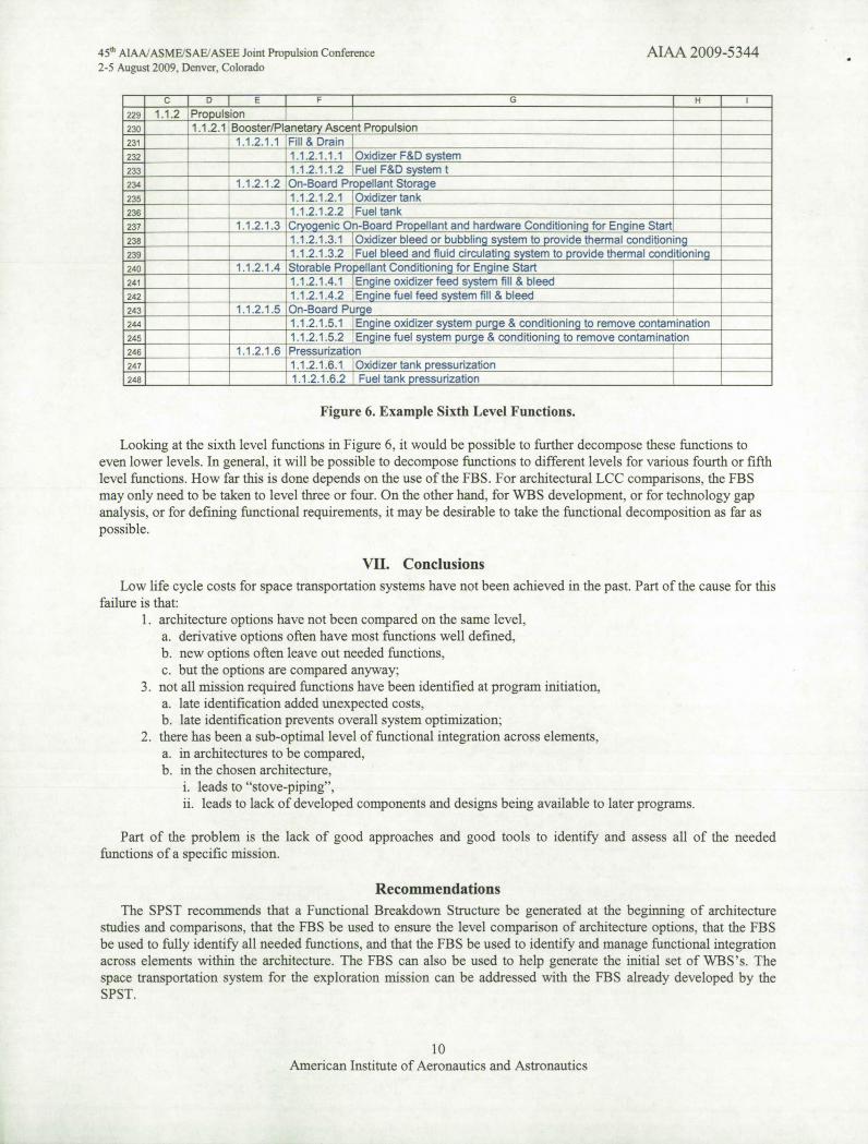
Finally, Figure 6 shows the sixth level functions that resulted from the decomposition on the first six of the fifth
level functions shown in Figure 5.
9 American Institute of Aeronautics and Astronautics
45th AIAA/ASME./SAEIASEE Joint Propulsion Conference
AIAA 2009-5344 2-5 August 2009. Denver. Colorado
= CD E F G I HI
229 1.1.2 Propulsion 1.1.2.1 Booster/Planetary Ascent Propulsion
1.1.2.1.1 Fill& Drain______ ______
1.1.2.1.1.1 Oxidizer F&D system_____ ______
1.1.2.1.1.2 Fuel F&D system______ ______
234 1.1.2.1.2 On-Board Propellant Storage______ ______
1.1.2.1.2.1 Oxidizertank______ ______
______ 1.1.2.1.2.2 Fueltank______
1.1.2.1.3 Cryogenic On-Board Propellant and hardware Conditioning for Engine Start ____________ ______
238 1.1.2.1.3.1 Oxidizer bleed or bubbling system to provide thermal conditioning ________1.1.2.1.3.2 ________ Fuel bleed and fluid circulating system to provide thermal conditioning
_______ _______
1.1.2.1.4 Storable Propellant Conditioning for Engine Start 24i 1.1.2.1.4.1 Engine oxidizer feed system fill & bleed _______
______ ______
_______
242 ________ 1.1.2.1.4.2 Engine fuel feed system fill & bleed ____________ _______
1.1.2.1.5 On-Board Purge 244 1.1.2.1.5.1
______ Engine oxidizer system purge & conditioning to remove contamination
______ _______
1.1.2.1.5.2 Engine fuel system purge & conditioning to remove contamination______
246
________
1.1.2.1.6 Pressurization_______
1.1.2.1.6.1 Oxidizer tank pressurization______ ______
1.1.2.1.6.2 Fueltank pressurization______________ ______________
Figure 6. Example Sixth Level Functions.
Looking at the sixth level functions in Figure 6, it would be possible to further decompose these functions to even lower levels. In general, it will be possible to decompose functions to different levels for various fourth or fifth level functions. How far this is done depends on the use of the FBS. For architectural LCC comparisons, the FBS may only need to be taken to level three or four. On the other hand, for WBS development, or for technology gap analysis, or for defining functional requirements, it may be desirable to take the functional decomposition as far as possible.
VII. Conclusions
Low life cycle costs for space transportation systems have not been achieved in the past. Part of the cause for this failure is that:
1. architecture options have not been compared on the same level, a. derivative options often have most functions well defined, b. new options often leave out needed functions, c. but the options are compared anyway;
3. not all mission required functions have been identified at program initiation, a. late identification added unexpected costs, b. late identification prevents overall system optimization;
2. there has been a sub-optimal level of functional integration across elements, a. in architectures to be compared, b. in the chosen architecture,
i. leads to "stove-piping", ii. leads to lack of developed components and designs being available to later programs.
Part of the problem is the lack of good approaches and good tools to identify and assess all of the needed functions of a specific mission.
Recommendations The SPST recommends that a Functional Breakdown Structure be generated at the beginning of architecture
studies and comparisons, that the FBS be used to ensure the level comparison of architecture options, that the FBS be used to fully identify all needed functions, and that the FBS be used to identify and manage functional integration across elements within the architecture. The FBS can also be used to help generate the initial set of \VBS's. The space transportation system for the exploration mission can be addressed with the FBS already developed by the SPST.
10 American Institute of Aeronautics and Astronautics

45th AIAA/ASME/SAEJASEE Joint Pmpulsion Conference
ATAA 2009-5344 2-5 August 2009, Denver, Colorado
References
Zapata, E., Levack, D. J. H., Rhodes, R, Robinson, J. W., "Shuttle Shortfalls and Lessons Learned for the Sustainment of Human Space Exploration", 45th AIAAIASME/SAE/ASEE Joint Propulsion Conference, AIAA 2009-5346, August 2009. 2 McCleskey, C. M., NASA TP-2005-2 11519, Space Shuttle Operations and Infrastructure, A Systems Analysis of Design Root Causes and Effects, NASA Kennedy Space Center, Florida, April 2005.
A Guide for the Design of Highly Reusable Space Transportation - Final Report, Space Propulsion Synergy Team (SPST), August29, 1997. "Penn, J. P., Odom, P. R., Rhodes, R., Dankhoff, W., "SPST Collaborative Prioritization of Advanced RLV Technologies Derived from a Bottom-Up Process", 37th AIAAJASME/SAE/ASEE Joint Propulsion Conference, AIAA 2001-3983, July 2001.
Rhodes, R., Dankhoff, W., Donahue, B., Christensen, D., "Current Space Shuttle System Shortfalls Assessment," SPST Space Propulsion Synergy Team report to NASA Headquarters Director of Strategic Investments, Sept 2005. 6 Buede, Dennis. M. The Engineering Design of Systems: Models and Methods. New York: John Wiley and Sons. 1999.
Shepard, Alan and Slayton, Deke. Moon Shot. The Inside Story of America's Race to the Moon. Turner Publishing, Inc. Atlanta, GA 1994. Pg 339. 8 DoD. Mil HDBK 881, DoD Handbook-- Work Breakdown Structure.January 1998. AMSC N/A. para 1.4.1.
11 American Institute of Aeronautics and Astronautics


![[Project Name]project-management.magt.biz/templates/02-scope-mgmt/02-120-wbs&… · WBS DICTIONARY The WBS Dictionary is a document that describes each WBS component including a brief](https://static.fdocuments.in/doc/165x107/5aedf65d7f8b9a90319062ce/project-nameproject-wbs-dictionary-the-wbs-dictionary-is-a-document-that-describes.jpg)