rockets guide
160
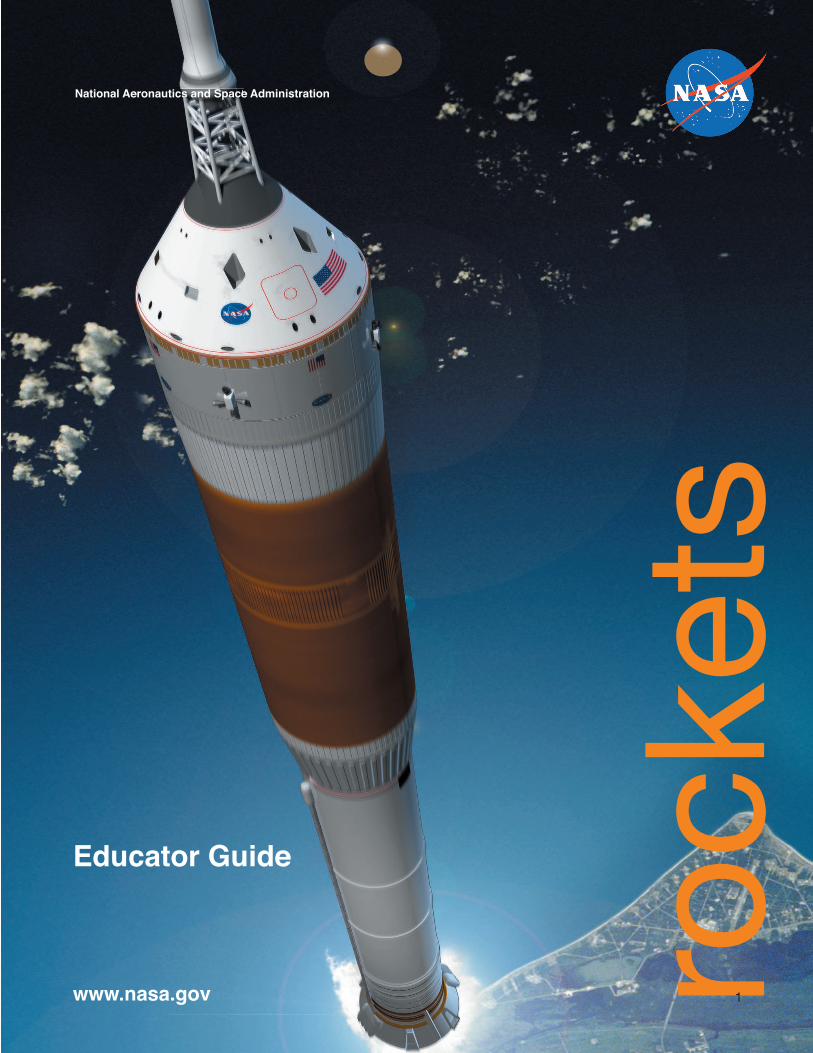
rockets 1 Educator Guide National Aeronautics and Space Administration www.nasa.gov
Transcript of rockets guide
rock
ets
1
Educator Guide
National Aeronautics and Space Administration
www.nasa.gov

2
DISCOVERY
AT
ES
UUUS
AS
AA
rocketPronunciation: \rä-kət\ noun (It rocchetta)
A vehicle, typically cylindrical, containing liquid or solid propellants which produce hot gases or ions that are ejected rearward through a nozzle and, in doing so, crU eates an action force accompanied by an opposite and equal r
NI eaction
force driving the vehicle forward. Because rT
E ockets are self-contained, they are able to operate in outer space.
D
ST
3
National Aeronautics and Space Administration
ROCKETS
Educator’s Guide with Activities in Science, Technology, Engineering and Mathematics
This publication is in the Public Domain and is not protected by copyright. Permission is not required for duplication.
EG-2008-05-060-KSC

i
AcknowledgementsThe original Rockets Teacher Guide was published by NASA’s Education Division in the mid-1990s. It has found widespread use in both formal and informal educational settings because of the exciting nature of the topic and because of its dynamic classroom activities that match and support both national and state education standards for science, mathematics, and technology.
This revision of the guide, by the original authors, updates educators on NASA’s 21st Century Space Exploration Policy and the vehicles that will make this vision possible. It builds on classroom experience with the original guide and presents a suite of improved and new activities that prepare students for the future of space exploration.
Many educators and scientists have contributed ideas and content directly and indirectly to this revision. Their assistance is gratefully appreciated.
Authors:Deborah A. Shearer
Principal, College Park Elementary LaPorte, Texas
Gregory L. Vogt, Ed.D.Educational consultant
Editor:Maury Solomon
Special Thanks To: NASA Headquarters Jerry G. Hartman Merrill King, Ph.D. Allota Taylor Carla Rosenberg Special appreciation is extended to NASA's Exploration SystemsMission Direcorate and Space Operations Mission Directorate for their generosity andcommitment to the continuationof this educational project. NASA Kennedy Space Center Gregg Buckingham, Ed.D. Lesley Garner, Ph.D. Sharon Fegan James Suderman
Marshall Space Flight Center Robert Armstrong Twila Schneider
Pennsylvania State University James Gerard Les Gold
Dynamac Corporation Michael Martin Valerie Jones
ii
Dear Educators:NASA has embarked on a 21st Century Space Exploration Policy that will establish a permanent human presence on the Moon and carry astronauts to Mars and beyond. The best ideas of our space exploring past are being merged with dreams for the future. It is a wonderful time for you and your students to learn about science, technology, engineering, and mathematics. Rockets will be your vehicle for learning.
The Rockets Educator Guide provides you and your students many opportunities. Together, you will examine early rockets and meet thinkers and dreamers. You will learn about rocket science and mathematics and what rocket scientists do. You will see pictures of events and technologies that many of us grew up with - Sputnik, Apollo and the Moon, and the space shuttle to name a few. You will see what the future of space transportation will look like. You will learn why rockets are the only vehicles we can use to “go where no one has gone before.”
Will your students be a part of this future in space? Will they be the scientists, technicians, engineers, and mathematicians that make dreams of exploring space possible? Yes! This guide will help you prepare them for the wonders that are coming.
Chapters within the guide present the history of rocketry, NASA’s 21st Century Space Exploration Policy, rocketry principles, and practical rocketry. These topics lay the foundation for what follows - a wealth of dynamic rocket science classroom activities that work. The activities focus on Sir Isaac Newton’s laws of motion and how they apply to rockets. They incorporate cooperative learning, problem solving, critical thinking, and hands-on involvement. They support national and state standards for science, mathematics, and technology across many grade levels.
All of the activities are designed with the classroom in mind. They include clear descriptions, background information for the teacher and student, detailed procedures and tips, lists of readily available materials, assessments, questions for discussion, and extensions. The activities are designed to foster excitement and a passion for learning.
The guide is versatile. It has been created as a two to six week classroom unit depending upon the grade level of the students but individual activities can be extracted and used as stand-alone classroom experiences. You will find activity objectives and principles clearly stated along with the vocabulary terms necessary for understanding the principles involved.
The goal of the Rockets Educator Guide is to excite young minds. Among your students are future leaders, planners, builders, explorers, settlers, and interplanetary pilots! This guide will help you lay the groundwork for their future in space.
iii
Table of ContentsLetter to Educators . . . . . . . . . . . . . . . . . . . . . . . . . . iiA Pictorial History of Rockets . . . . . . . . . . . . . . . . . . 1What Comes Next . . . . . . . . . . . . . . . . . . . . . . . . . . . 13How Rockets Work . . . . . . . . . . . . . . . . . . . . . . . . . . 19Applying Newton’s Laws . . . . . . . . . . . . . . . . . . . . . . 24
Activities . . . . . . . . . . . . . . . . . . . . . . . . . . . . . . . . . . 30 National Standards Matrix . . . . . . . . . . . . . . . . . . 31 Suggested Grade Levels . . . . . . . . . . . . . . . . . . . 33 Pop Can “Hero Engine” . . . . . . . . . . . . . . . . . . . . 34 3...2...1...PUFF!. . . . . . . . . . . . . . . . . . . . . . . . . . . 40 Heavy Lifting. . . . . . . . . . . . . . . . . . . . . . . . . . . . . 46 Newton Car . . . . . . . . . . . . . . . . . . . . . . . . . . . . . 51 Rocket Races . . . . . . . . . . . . . . . . . . . . . . . . . . . . 56 Pop! Rocket Launcher . . . . . . . . . . . . . . . . . . . . . 63 Pop! Rockets . . . . . . . . . . . . . . . . . . . . . . . . . . . . 66 Foam Rocket . . . . . . . . . . . . . . . . . . . . . . . . . . . . 72 Launch Altitude Tracker . . . . . . . . . . . . . . . . . . . . 80 High-Power Paper Rocket Launcher . . . . . . . . . . 86 High-Power Paper Rockets . . . . . . . . . . . . . . . . . 91 Rocket Wind Tunnel . . . . . . . . . . . . . . . . . . . . . . . 97 Advanced High-Power Paper Rockets . . . . . . . 103 Water Rocket Launcher . . . . . . . . . . . . . . . . . . 109 Water Rocket Construction . . . . . . . . . . . . . . . 114 Project X-51 . . . . . . . . . . . . . . . . . . . . . . . . . . . 118 Rocket Scientist Certificate . . . . . . . . . . . . . . . 138 Careers . . . . . . . . . . . . . . . . . . . . . . . . . . . . . . . 139 Above and Beyond-Additional Explorations . . . 140
How High? . . . . . . . . . . . . . . . . . . . . . . . . . . 141Science Fiction . . . . . . . . . . . . . . . . . . . . . . 144Space Art . . . . . . . . . . . . . . . . . . . . . . . . . . . 146
Glossary . . . . . . . . . . . . . . . . . . . . . . . . . . . . . . . . . 148NASA Educational Resources . . . . . . . . . . . . . . . . . 149Evaluation . . . . . . . . . . . . . . . . . . . . . . . . . . . . . . . 151
1
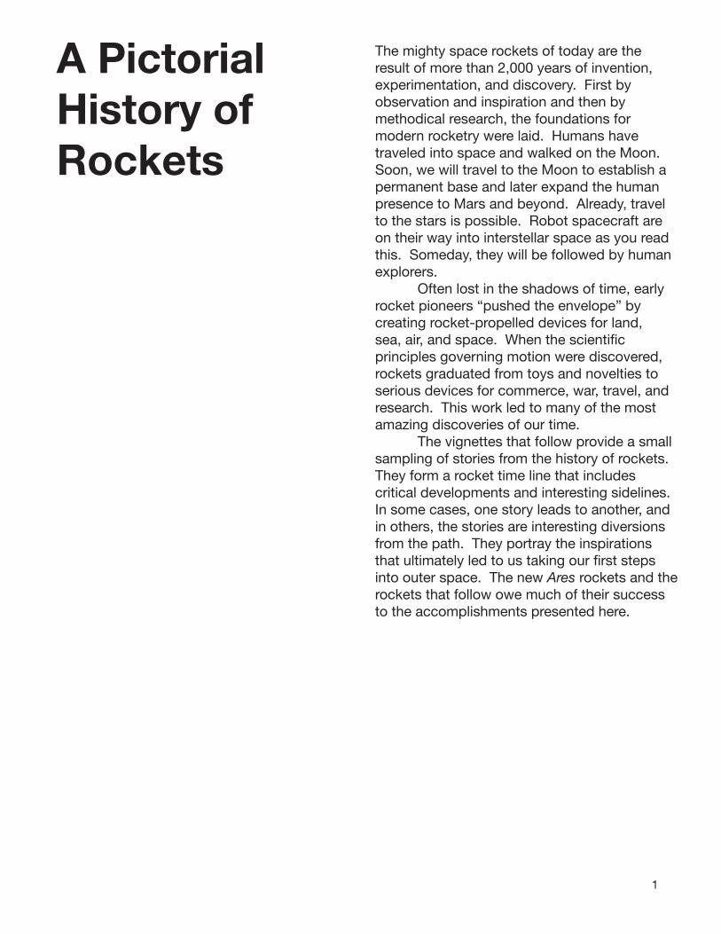
A Pictorial History of Rockets
The mighty space rockets of today are the result of more than 2,000 years of invention, experimentation, and discovery. First by observation and inspiration and then by methodical research, the foundations for modern rocketry were laid. Humans have traveled into space and walked on the Moon. Soon, we will travel to the Moon to establish a permanent base and later expand the human presence to Mars and beyond. Already, travel to the stars is possible. Robot spacecraft are on their way into interstellar space as you read this. Someday, they will be followed by human explorers. Often lost in the shadows of time, early rocket pioneers “pushed the envelope” by creating rocket-propelled devices for land, sea, air, and space. When the scientific principles governing motion were discovered, rockets graduated from toys and novelties to serious devices for commerce, war, travel, and research. This work led to many of the most amazing discoveries of our time. The vignettes that follow provide a small sampling of stories from the history of rockets. They form a rocket time line that includes critical developments and interesting sidelines. In some cases, one story leads to another, and in others, the stories are interesting diversions from the path. They portray the inspirations that ultimately led to us taking our first steps into outer space. The new Ares rockets and the rockets that follow owe much of their success to the accomplishments presented here.

2
Steam, Sparks, Explosions, and Flight
Archytas, 428 to 347 B.C.Archytas, a Greek philosopher, mathematician, and astronomer was said to have constructed and fl own a small bird-shaped device that was propelled by a jet of steam or compressed air. The ‘bird’ may have been suspended by a wire or mounted at the end of a bar that revolved around some sort of pivot. This was the fi rst reported device to use rocket propulsion.
Hero Engine, c. A.D. 10 to 70 Though not a rocket, the main principle behind rocket (and jet) propulsion was employed in a steam engine invented by Hero of Alexandria. The exact appearance of Hero’s engine is not known, but it consisted of some sort of copper vessel heated by a fi re beneath. Water in the vessel turned into steam and traveled up two tubes to a hollow sphere that was free to rotate. Two L-shaped tubes from the sphere allowed the steam to escape in jets of gas. The sphere rotated rapidly in the opposite direction of the jets. The Hero engine was seen as an amusing toy, and its potential was not realized for a thousand years.
Chinese Fire Arrows, A.D. 1232The origins of gunpower are not clear, but the Chinese reportedly had a rudimentary form of it in the fi rst century, A.D. A mixture of saltpeter, sulfur, and charcoal dust produced colorful sparks and smoke when ignited. The powder was used to make fi reworks. Tubes of bamboo and leather, closed off at one end, were packed with gunpowder. Depending upon how the powder was packed and the size of the opening, a fountain of sparks or a bang would result when the powder was ignited. It is likely that some fi reworks skittered about because of the thrust produced from the gases escaping the open end. Thus the rocket was born. By 1232, these primitive rockets were attached to arrows and used to repel Mongol invaders in the battle of Kai-keng.
Roger Bacon, c. 1214 to c. 1292A monk, Bacon wrote about gunpowder in his The Epistola Fratris R. Baconis, de secretis operibus artis et naturase et nullitate magiae:“We can, with saltpeter and other substances, compose artifi cially a fi rethat can be launched over long distances....By only using a very small quantity of this material much light can be created accompanied by a horrible fracas. It is possible with it to destroy a town or an army....” Bacon is thought to have developed improved gunpowder formulas that greatly increased the mixture’s power.
3
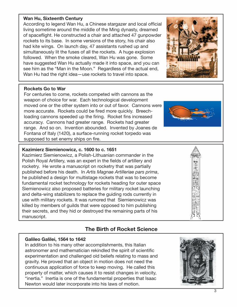
Wan Hu, Sixteenth CenturyAccording to legend Wan Hu, a Chinese stargazer and local official living sometime around the middle of the Ming dynasty, dreamed of spaceflight. He constructed a chair and attached 47 gunpowder rockets to its base. In some versions of the story, his chair also had kite wings. On launch day, 47 assistants rushed up and simultaneously lit the fuses of all the rockets. A huge explosion followed. When the smoke cleared, Wan Hu was gone. Some have suggested Wan Hu actually made it into space, and you can see him as the “Man in the Moon.” Regardless of the actual end, Wan Hu had the right idea—use rockets to travel into space.
Rockets Go to WarFor centuries to come, rockets competed with cannons as the weapon of choice for war. Each technological development moved one or the other system into or out of favor. Cannons were more accurate. Rockets could be fired more quickly. Breech-loading cannons speeded up the firing. Rocket fins increased accuracy. Cannons had greater range. Rockets had greater range. And so on. Invention abounded. Invented by Joanes de Fontana of Italy (1420), a surface-running rocket torpedo was supposed to set enemy ships on fire.
Kazimierz Siemienowicz, c. 1600 to c. 1651Kazimierz Siemienowicz, a Polish-Lithuanian commander in the Polish Royal Artillery, was an expert in the fields of artillery and rocketry. He wrote a manuscript on rocketry that was partially published before his death. In Artis Magnae Artilleriae pars prima, he published a design for multistage rockets that was to become fundamental rocket technology for rockets heading for outer spaceSiemienowicz also proposed batteries for military rocket launchingand delta-wing stabilizers to replace the guiding rods currently in use with military rockets. It was rumored that Siemienowicz was killed by members of guilds that were opposed to him publishing their secrets, and they hid or destroyed the remaining parts of his manuscript.
The Birth of Rocket Science
Galileo Galilei, 1564 to 1642In addition to his many other accomplishments, this Italian astronomer and mathematician rekindled the spirit of scientific experimentation and challenged old beliefs relating to mass and gravity. He proved that an object in motion does not need the continuous application of force to keep moving. He called this property of matter, which causes it to resist changes in velocity, “inertia.” Inertia is one of the fundamental properties that Isaac Newton would later incorporate into his laws of motion.
4
Newton’s Laws of Motion, 1642 to 1727English scientist Sir Isaac Newton condensed all rocket science into three elegant scientific laws. Published in Philosophiae Naturalis Principia Mathematica his laws, previously understood intuitively by early rocketeers, provided the foundation for all modern rocket science. (The “Rocket Principles” chapter focuses on these laws and the “Practical Rocketry” chapter demonstrates the applications of these laws.)
Colonel William Congreve, 1772 to 1828Following stunning rocket barrages against the British by the forces of Tippoo Sultaun of India, William Congreve took charge of British military rocket companies. Some of his designs had operational ranges of 6,000 yards. He created both case-shot rockets that sprayed the enemy with carbine balls and incendiary rockets for burning ships and buildings. He invented launching rockets from ships. The phrase “by the rocket’s red glare,” coined by Francis Scott Key during the War of 1812, referred to British-launched Congreve rockets.
Jules Verne, 1828 to 1905The dream of traveling through space was brought to life by French science fiction writer Jules Verne. In his De la Terre á la Lune, Verne used a giant cannon to fire a manned projectile at the Moon. Although not a rocket, the projectile had some interesting parallels with the future Apollo Moon program. It was called the Columbiad and contained a crew of three. It was fired at the Moon from Florida. The Apollo 11 capsule was named Columbia, contained a crew of three, and was launched from Florida. Verne correctly described how the crew would feel “weightless” on their voyage. Of course, the crew would not have survived the initial acceleration of the cannon firing. Nevertheless, Verne, an early space exploration visionary, fired the imaginations of many would-be rocketeers and future astronauts.
Modern Rocket Pioneers
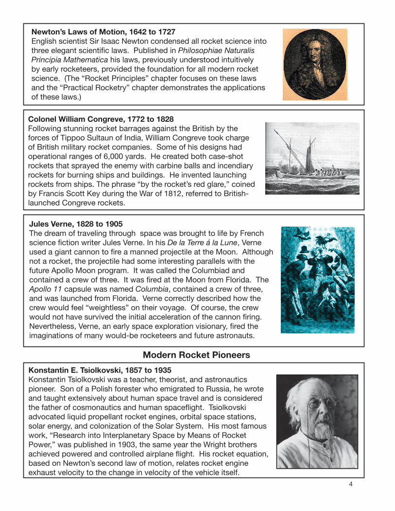
Konstantin E. Tsiolkovski, 1857 to 1935Konstantin Tsiolkovski was a teacher, theorist, and astronautics pioneer. Son of a Polish forester who emigrated to Russia, he wrote and taught extensively about human space travel and is considered the father of cosmonautics and human spaceflight. Tsiolkovski advocated liquid propellant rocket engines, orbital space stations, solar energy, and colonization of the Solar System. His most famous work, “Research into Interplanetary Space by Means of Rocket Power,” was published in 1903, the same year the Wright brothers achieved powered and controlled airplane flight. His rocket equation, based on Newton’s second law of motion, relates rocket engine exhaust velocity to the change in velocity of the vehicle itself.

5
Robert H. Goddard, 1882 to 1945American college professor and scientist Robert Goddard built and flew the world’s first liquid propellant rocket on March 16, 1926. Its flight, though unimpressive (it climbed only 12.5 meters), was the forerunner of the Saturn V Moon rocket 43 years later. At the request of local townsfolk, Goddard moved his experiments from Auburn, Massachusetts, to the deserts around Roswell, New Mexico. There he continued his experiments and developed a gyroscope system to control his rockets in flight, instrumentation payload compartments, and parachute recovery systems. He is often referred to as the “father of modern rocketry.”
Hermann Oberth, 1894 to 1989Hermann Oberth, a Romanian by birth and a naturalized German citizen, became fascinated by the works of Jules Verne and devoted his life to promoting space travel. His dissertation for the University of Heidelberg, rejected for being too speculative, became the basis for his book Die Rakete zu den Planetanraumen (By Rocket to Space). The book explained the mathematics of spaceflight and proposed practical rocket designs and space stations. This and other books inspired a generation of rocketeers. Rocket societies sprang up around the world, including the German Verein fur Raumschiffart (Society for Space Travel) that led to the development of the V2 rocket.
Rocket Experimenters, Early Twentieth CenturyIn the 1920s and 1930s, leading up to World War II, amateur rocketeers and scientists worldwide attempted to use rockets on airplanes, racing cars, boats, bicycles with wings, throw lines for rescuing sailors from sinking ships, mail delivery vehicles for off-shore islands, and anything else they could dream up. Though there were many failures, experience taught the experimenters how to make their rockets more powerful and more reliable.
World War II
Flying BombsThe necessities of war led to massive technological improvements in aeronautics and rocketry. Almost overnight, rockets graduated from novelties and dream flying machines to sophisticated weapons of destruction. Rockets propelled nearly unstoppable German fighter planes and Japanese Kamikaze pilots with bombs into ships. War would never be the same again.
6
Vergeltungswaffe 2 - V2In the late 1930s, the German Verein fur Raumschiffart Society for Space Travel evolved into the team that built and flew the most advanced rocket for the time, the V2. On the shores of the Baltic Sea, the team, under the directorship of Wernher von Braun, created a rocket powered by alcohol and liquid oxygen. With a range of 320 kilometers (200 miles) and a maximum altitude of 88 kilometers (55 miles), the V2 could deliver a 1-ton explosive warhead to the heart of London without warning. Thousands of V2s were built, but they entered the war too late to affect the outcome.
The Space Age Begins
Bumper ProjectAt the conclusion of the war in Europe, 300 trainloads of V2 rockets and parts were captured and shipped to the United States along with the majority of the principal designers, who decided beforehand to surrender to American troops. The V2 became the basis of the intercontinental ballistic missile development program and led directly to the manned space program. Employing one of the captured V2 rockets with a WAC Corporal rocket (named for the Women’s Army Corps) at its top, the initial launch of a “BumperWAC” took place on May 13, 1948. During six flights, the largest two-stage rocket launched to date in the United States eventually reached an altitude of almost 400 kilometers (250 miles).
-
The World’s First Artificial SatelliteAt the conclusion of World War II, the United States and the Soviet Union engaged in a race for space. The Soviet Union won the first round by launching its Sputnik I satellite on October 4, 1957. The satellite had a spherical design with four antenna. It weighed 83.6 kilograms (184.3 pounds). Two months later, the 508.3-kilogram (1,118.26-pound) Sputnik II reached space with a living passenger. Laika, a small dog, orbited Earth for a few hours. Although she died in space, she led the way for all humans that followed.
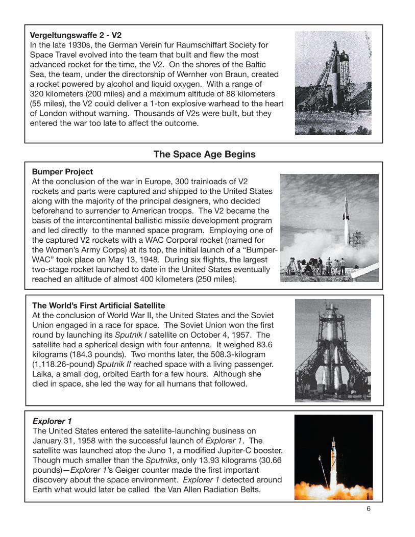
Explorer 1The United States entered the satellite-launching business on January 31, 1958 with the successful launch of Explorer 1. The satellite was launched atop the Juno 1, a modified Jupiter-C booster. Though much smaller than the Sputniks, only 13.93 kilograms (30.66 pounds)—Explorer 1’s Geiger counter made the first important discovery about the space environment. Explorer 1 detected around Earth what would later be called the Van Allen Radiation Belts.

7
X-15Between 1959 and 1968, the X-15 experimental aircraft flew to the edge of space. In 199 flights, the air-launched rocket plane broke many flight records, including speed (7,274 kph or 4,520 mph) and altitude records (108 kilometers or 67 miles). Test flightsestablished important parameters for attitude control in space and reentry angles. Neil Armstrong, the first American to step on the Moon, was one of twelve X-15 pilots.
Yuri Gagarin Goes Into OrbitOn April 12, 1961, space became the domain of humans with the launch of cosmonaut Yuri Gagarin. His spaceflight lasted 1 hour and 48 minutes. During that time, Gagarin orbited Earth one time inside his Vostok 1 space capsule, reaching a maximum altitude of 315 kilometers (196 miles). Upon reentry, Gagarin ejected himself from the capsule at an altitude of 6,100 meters (20,000 feet) and parachuted safely to the ground.
Freedom 7 On May 5, 1961, American astronaut Alan Shepherd, Jr., lifted off from Cape Canaveral, Florida, inside his Freedom 7 Mercury space capsule, which sat atop a Redstone rocket. The rocket did not have enough power to send the craft into orbit, and Shepherd madea suborbital flight reaching 187 kilometers (116 miles) before his capsule returned to Earth in an ocean splashdown 15 minutes 22 seconds later.
Moon RocketJust days after Alan Shepard’s flight, President John F. Kennedy addressed a joint session of Congress and challenged America to send an American to the Moon and return him safely before the end of the decade. Although it was a shockingly bold announcement, some of the steps to accomplish this mission were already underway. NASA had begun work on components of a rocket capable of a round trip lunar flight. By the next year, the rocket was named the Saturn V. It would be 110.6 meters or 363 feet tall, dwarfing all previous rockets.The Saturn V would consist of three stages, a capsule with a small propulsion unit for the return trip, and a two-stage lunar lander.

8
Glenn Orbits EarthOn February 20, 1962, riding on a more powerful missile, the Atlas, astronaut John H. Glenn, Jr., became the first American to go into orbit. Glenn’s flight achieved parity with the Soviet program. Glenn orbited Earth three times for a total of 4 hours and 55 minutes in space. A sensor switch led to an early return. The sensor indicated that the Mercury capsule heat shield was loose, but the shield was later determined to be firmly in place during flight. The sensor was faulty. The last of the six Mercury flights took place on May 15, 1963, with astronaut Gordon Cooper remaining in space for nearly a day and a half.
Preparing for the MoonProject Gemini followed the Mercury missions. The Gemini space capsule, riding on top of a Titan missile, contained two astronauts. During missions lasting up to 14 days, Gemini astronauts pioneered spacewalking, spacecraft rendezvous, and docking procedures. Important spacecraft systems, needed for the coming Moon flights, were evaluated. Ten Gemini missions were flown during 1965 and 1966. The Titan rocket, initially created as an intercontinental ballistic missile, went on to carry the Viking spacecraft to Mars and the Voyager spacecraft to the outer solar system in the 1970s.
Dr. Wernher von BraunOne of the leading figures in the development of pre-war Germany’s rocket program and the development of the V2 missile, von Braun (1912-1977) became a leading proponent of America’s space program. He entered the United States after the war and became a naturalized citizen. He worked on the development of intercontinental ballistic missiles and led the development team that launched Explorer 1. Dr. von Braun was the chief architect and engineer of the Saturn V Moon rocket. His popular writings and collaboration with Disney on a “Tomorrowland” TV series did much to inspire the next generation of rocket scientists and astronauts.
Gene RoddenberryGene Roddenberry (1921-1991), a distinguished World War II bomber pilot and commercial pilot, began his writing career penning stories about flying. He began writing for television and developed a concept for a “western” series set among the stars. For three years (1966–1968), the Star Trek seriesexplored a wide range of scientific and social issues as humans traveled across the galaxy. The series became so popular that the first space shuttle orbiter test vehicle was named Enterprise after the star ship Enterprise. The original show spawned several companion series and a string of movies. Roddenberry, a visionary, inspired a generation of space travelers.

9
“One Small Step...”At 10:56 p.m. EDT, July 20, 1969, American astronaut Neil Armstrong set foot on the Moon. It was the first time in history that humans had touched another world. He was followed to the surface by Edwin “Buzz” Aldrin, Jr. A third astronaut, Michael Collins, remained in lunar orbit in the Apollo capsule. The Apollo 11 mission was the first of six Moon landings extending to the end of 1972. The astronauts’ spacecraft, the lunar module, consisted of a descent and an ascent stage. The descent stage had four legs and a powerful rocket engine to slow the craft for landing on the Moon. After surface explorations, the upper part of the lander lifted off, using its own rocket engine, and rendezvoused with the Apollo capsule for the return to Earth.
SkylabUsing a modified third stage of the Saturn V rocket, the United States finally launched its first space station, called Skylab, into Earth orbit in 1973. Rather than engines and fuel tanks, the interior of the third stage was fitted with living quarters and laboratories for three astronauts on extended stays in space. Solar panels provided electric power. Due to a problem during launch, one of the large panels was lost. Nevertheless, three crews of astronauts called Skylab home until 1974. The last crew remained in space 84 days.
Smaller SaturnThe Saturn V rocket was capable of launching 117,900 kilograms (260,000 pounds) into low Earth orbit and 40,800 kilograms (90,000 pounds) to the Moon. For some Apollo missions, though, a smaller Saturn was called for. The Saturn IB was 68 meters (224 feet) tall and required a scaffold platform nicknamed the “milk stool” to be placed on the pad designed for Saturn V rockets. This enabled the Saturn IB to match up with swing arms from the launch structure. The Saturn IB carried some of the early Apollo test missions, the three crews for Skylab, and the American crew for the 1975 historic Apollo-Soyuz mission, linking astronauts and cosmonauts in orbit.
Orbits and Probes
Deep SpaceThe Titan rockets (1959–2005), used for launching the Gemini missions, found wide use in launching unmanned payloads. Upgraded versions of Titans lofted heavy satellites into Earth orbit and propelled important spacecraft to other planets. The Viking missions to Mars and the Voyager missions to the outer planets and interstellar space are among its credits.
10
Sounding RocketsAlthough rockets have generally gotten larger and more powerful, there are many reasons for flying smaller rockets. The Canadian– designed Black Brant sounding rocket has been flying since 1961 and has successfully completed over 800 flights carrying small payloads such as cameras, instruments, and microgravity experiments. The Black Brant’s reliability and low cost has made it a favorite of researchers. The biggest multistage Black Brants have payload capacities of about 100 kilograms (220 pounds) and can reach altitudes of up to 900 kilometers (560 miles).
ArianeBeginning service in 1979 and continuing today with upgraded versions, the European Space Agency’s Ariane rocket has specialized in launching communications satellites to high geostationary orbits. Ariane is launched from French Guiana on the eastern coast of South America to take maximum advantage of Earth’s rotational velocity in boosting the rocket into orbit.
Delta FamilyWith roots going back to the early 1960s, the American Delta rocket is one of the most versatile of the commercial and military payload launch rockets. Delta has many configurations, including multiple stages and heavy-lift strap-on boosters that increase payload capacity to high orbits. The Delta family has logged more than 325 launches, with a success rate exceeding 95 percent.
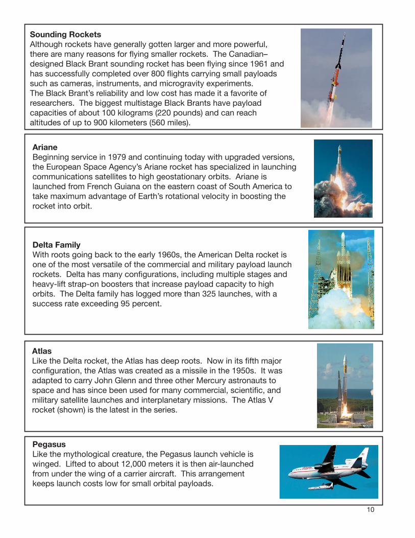
Atlas Like the Delta rocket, the Atlas has deep roots. Now in its fifth major configuration, the Atlas was created as a missile in the 1950s. It was adapted to carry John Glenn and three other Mercury astronauts to space and has since been used for many commercial, scientific, and military satellite launches and interplanetary missions. The Atlas V rocket (shown) is the latest in the series.
PegasusLike the mythological creature, the Pegasus launch vehicle is winged. Lifted to about 12,000 meters it is then air-launched from under the wing of a carrier aircraft. This arrangement keeps launch costs low for small orbital payloads.
11
The Space Shuttle and International Space Station (ISS) Era
A New Kind of Launch VehicleAt the completion of the Apollo program, American rocket scientists began building a new system for carrying crews and payloads into low Earth orbit, the space shuttle transportation system. A four-part vehicle arranged around a central external tank, the shuttle system contains liquid hydrogen and oxygen that feeds the main engines of the airplane-like orbiter. On the sides of the tank are two solid rocket boosters. Partway into orbit, the spent boosters separate for return to Earth by parachute for ocean recovery and reuse. The orbiter and tank continue towards orbit. When exhausted, the tank drops and disintegrates on reentry. The orbiter continues on the power of its orbital maneuvering system engines. Once in orbit, payload bay doors open to expose the payload — science laboratories, space probes, telescopes, or Earth-sensing systems. At the end of the mission, the orbiter reenters Earth’s atmosphere and glides to an unpowered landing on a runway. The first space shuttle flight took place on April 20, 1981.
Serving the ISSThe first flight of the space shuttle took place in 1981. More than 120 missions have been completed. Since 1998, the principal mission of the space shuttle has been to ferry components for construction, crews, supplies, and experiments to the ISS. When the station is completed, the space shuttle will be retired.
International PartnershipsIn addition to the United States, fifteen other nations support the ISS in a variety of ways. Russia, a major participant, uses its Soyuz rocket to launch crews of three to the station and to launch its Progress robotic supply spacecraft. Other partners include Canada, Belgium, Denmark, France, Germany, Italy, The Netherlands, Norway, Spain, Sweden, Switzerland, The United Kingdom, Japan, and Brazil.
Space Tourism
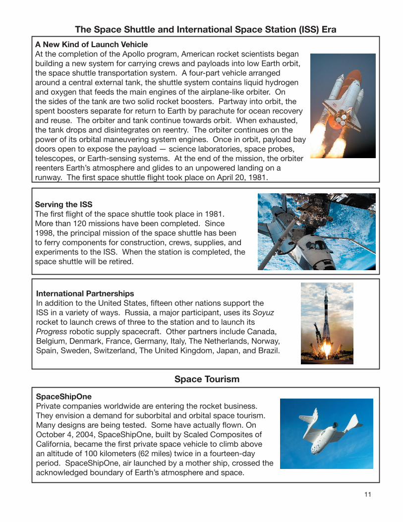
SpaceShipOnePrivate companies worldwide are entering the rocket business. They envision a demand for suborbital and orbital space tourism. Many designs are being tested. Some have actually flown. On October 4, 2004, SpaceShipOne, built by Scaled Composites of California, became the first private space vehicle to climb above an altitude of 100 kilometers (62 miles) twice in a fourteen-day period. SpaceShipOne, air launched by a mother ship, crossed theacknowledged boundary of Earth’s atmosphere and space.
And Beyond?
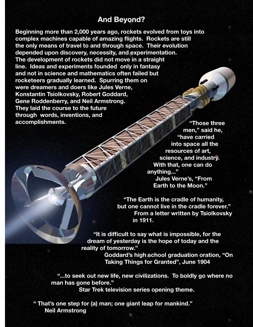
Beginning more than 2,000 years ago, rockets evolved from toys into complex machines capable of amazing flights. Rockets are still the only means of travel to and through space. Their evolution depended upon discovery, necessity, and experimentation. The development of rockets did not move in a straight line. Ideas and experiments founded only in fantasy and not in science and mathematics often failed but rocketeers gradually learned. Spurring them on were dreamers and doers like Jules Verne, Konstantin Tsiolkovsky, Robert Goddard, Gene Roddenberry, and Neil Armstrong. They laid the course to the future through words, inventions, and accomplishments. “Those three
men,” said he, “have carried
into space all the resources of art,
science, and industry. With that, one can do
anything...” Jules Verne’s, “From
Earth to the Moon.”
“The Earth is the cradle of humanity, but one cannot live in the cradle forever.”
From a letter written by Tsiolkovsky in 1911.
“It is difficult to say what is impossible, for the dream of yesterday is the hope of today and the
reality of tomorrow.” Goddard’s high school graduation oration, “On
Taking Things for Granted”, June 1904
“...to seek out new life, new civilizations. To boldly go where no man has gone before.”
Star Trek television series opening theme.
“ That’s one step for (a) man; one giant leap for mankind.”Neil Armstrong 12
13
What Comes Next
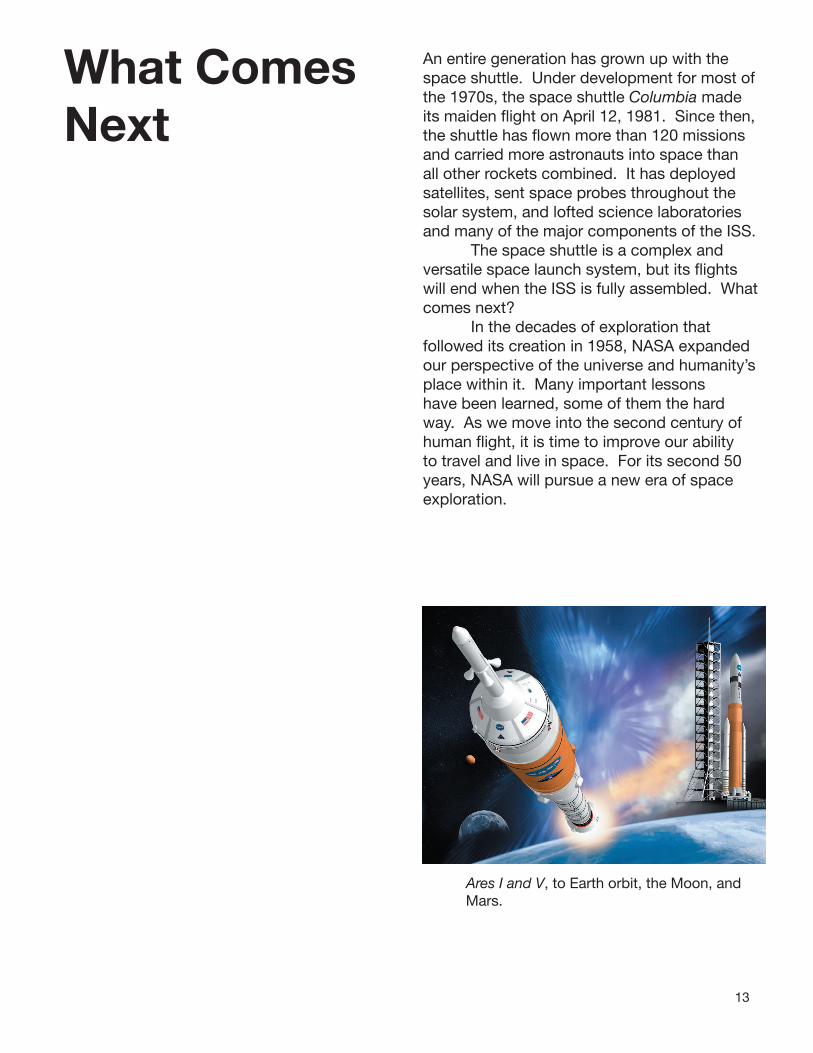
An entire generation has grown up with the space shuttle. Under development for most of the 1970s, the space shuttle Columbia made its maiden flight on April 12, 1981. Since then, the shuttle has flown more than 120 missions and carried more astronauts into space than all other rockets combined. It has deployed satellites, sent space probes throughout the solar system, and lofted science laboratories and many of the major components of the ISS. The space shuttle is a complex and versatile space launch system, but its flights will end when the ISS is fully assembled. What comes next? In the decades of exploration that followed its creation in 1958, NASA expanded our perspective of the universe and humanity’s place within it. Many important lessons have been learned, some of them the hard way. As we move into the second century of human flight, it is time to improve our ability to travel and live in space. For its second 50 years, NASA will pursue a new era of space exploration.
Ares I and V, to Earth orbit, the Moon, and Mars.

14
Human Space Flight Objectives for the Second Fifty Years:• Implement a sustainable and affordable
human and robotic exploration program throughout the solar system and beyond.
• Build a permanent outpost on the Moon and prepare for human exploration of Mars.
• Develop the innovative technologies, knowledge base, and infrastructure needed tosupport and sustain human exploration.
• Promote international and commercial participation leading to furthering U. S. scientific, security, and economic interests.
Essential to NASA’s plans is a new and versatile space launch system to space shuttle. Capitalizing on NASA’s multi-decade experience, the new system will combine the best of the past with the best of the present and future. It is called the Constellation program and will consist of two launch vehicles, each with different configurations to meet varying mission and cost requirements. For maximum crew safety, the Constellation program separates human crews and payloads. The crew launch vehicle is called the Ares I and it is capped with the Orion crew exploration vehicle. The heavy-lift unmanned payload vehicle is the Ares V.
Ares I Crew Launch VehicleThe Ares rockets take their name from the Greek word for the planet Mars. Ares I is an in-line, two-stage rocket with a crew capsule on top. The first stage is derived from the space shuttle’s solid rocket boosters. The space shuttle uses two boosters, each consisting of four segments joined end-to-
replace the
end. The Ares I first stage is a single booster with five segments. Like the space shuttle’s boosters, it will be recoverable from the ocean for reuse. Resting on top of the first stage will be a interstage with mechanisms and small rocket motors used for separating the first and upper stages. The upper stage, resembling the external tank of the space shuttle, is a new vehicle with a liquid hydrogen liquid oxygen J-2X engine at its base. Derived from the Saturn rockets of the Apollo era, the J-2X engine is an upgraded version of the J-2 engines used for the second and third stages of the Saturn V. The J-2X will consume liquid hydrogen and liquid oxygen propellants contained in large tanks within the upper stage.
Orion
Ares I
LaunchAbort System
Service Module
Adapter
Upper Stage
Interstage
First Stage
Ares V
Nose Cone(shroud)
Altair lunar lander(inside)
EarthDepartureStage
Interstage
First StageCore
First StageSRBs

15
.On top of the second stage will be an instrumented adapter ring that will connect to the Orion crew exploration vehicle. Orion will consist of two modules, similar to but larger than the crew modules used for Apollo. A service module, containing propellants for a single rocket engine and power systems for the crew module, will perch directly on top of the upper stage adapter. The crew module, a cone-shaped capsule, will be mounted on top of the service module. It will be large enough to carry six astronauts to the ISS or four astronauts to the Moon. On lunar missions, the crew of Orion will rendezvous with a lunar landing craft launched into Earth orbit by Constellation’s cargo vehicle, Ares V. Lastly, a thick, pencil-shaped launch abort system attaches directly to the apex of the crew module. The abort system has a cluster of small rocket engines angled outward from the capsule below. The abort system enhances crew safety during the launch phase. In the event of an emergency, its rockets will pull the Orion away from the Ares I stack so that the capsule can parachute safely into the ocean. When Orion is successfully launched, the launch abort system will be jettisoned. Another significant safety improvement of the Orion design is the placement of the capsule above the Ares I upper stage. Orion will be out of harm’s way from colliding with any ice or insulation material that might vibrate loose and fall during launch. Orion with the launch abort
Ares I on the launch pad.
Ares V Cargo Launch VehicleAres V will become NASA’s primary heavy-lift cargo launch vehicle. Like Ares I, it will be derived from earlier launch systems and will consist of two stages. The first stage will be assembled around a cylindrical core vehicle containing liquid hydrogen and liquid oxygen. The core design is based on proven technology for the Saturn V rocket. At the base of the core stage will be five RS-68 engines upgraded from engines currently used in the Delta IV rocket. Flanking the core will be two five-segment solid rocket boosters. For lunar missions, an Earth departure stage (EDS) will be mounted on top of the core stage adapter rings. The EDS, propelled by liquid hydrogen and oxygen, will employ a J-2X engine. Above the EDS and covered by a nose cone shroud will be the Altair lunar lander. The shroud will be jettisoned once the lander is in orbit, exposing the lander and its docking adapter to space.

16
Ares V ready for flight.
ISS MissionsFor missions to the ISS, only the Ares I rocket will be flown. Up to six astronauts will ride in the Orion capsule. The Ares I launch will be carefully timed to make sure Orion arrives in orbit in a favorable position to rendezvous with the station. Using the engine on the service module, the crew will approach the station. Small clusters of attitude control rockets, along the outside of the service module, will permit minor velocity changes and adjustments in the direction (attitude) Orion points. Slowly moving forward, the docking adapter mounted in the apex of the Orion cone is pushed onto and locked to the matching adapter on the station. Airlock doors open, and the crew transfers into the station along with supplies. Orion will have the ability to remain docked to the ISS for six months at a time. It will serve as a “lifeboat” for emergency evacuation of station crews. Orion will also be able to deliver large quantities of supplies to the station in an automatic, unpiloted flight mode.
Orion approaching the International Space Station.
Ares V lifts the Earth departure stage and Altair lunar lander to orbit.
To The MoonFor missions to the Moon, both Ares I and Ares V will be deployed. In orbit, the crew of Orion will begin maneuvers for rendezvous. Orion docks with the Altair lunar lander mounted on the forward end of the EDS. Once a hard dock is achieved, an interconnecting airlock door is opened, and the crew can pass from Orion into the lander and back again. When ready, the EDS fires its engine and sends Orion and the lander towards the Moon. At this point, the EDS will have completed its mission. It will leave Orion and the lander and propel itself out of the way into a long-period solar orbit. For the next three days, Orion and lander will coast to the Moon. The crew will rotate the combined vehicle so that the engine of the lander is aimed in the direction of the Moon. The Altair lunar lander will be functionally similar to the landing vehicles used for the Apollo Moon landings. It will consist of two stages. The descent stage has four landing pod legs that will unfold and a large landing
17
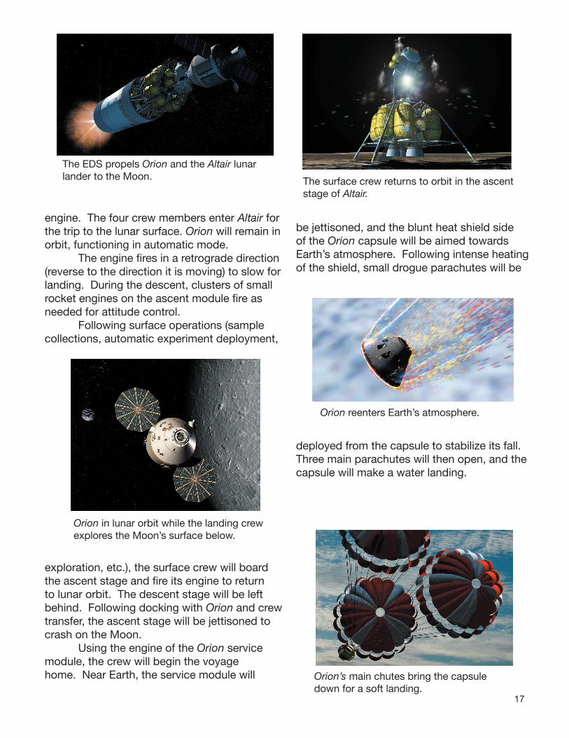
engine. The four crew members enter Altair for the trip to the lunar surface. Orion will remain in orbit, functioning in automatic mode. The engine fires in a retrograde direction (reverse to the direction it is moving) to slow for landing. During the descent, clusters of small rocket engines on the ascent module fire as needed for attitude control. Following surface operations (sample collections, automatic experiment deployment,
exploration, etc.), the surface crew will board the ascent stage and fire its engine to return to lunar orbit. The descent stage will be left behind. Following docking with Orion and crew transfer, the ascent stage will be jettisoned to crash on the Moon. Using the engine of the Orion service module, the crew will begin the voyage home. Near Earth, the service module will
be jettisoned, and the blunt heat shield side of the Orion capsule will be aimed towards Earth’s atmosphere. Following intense heating of the shield, small drogue parachutes will be
deployed from the capsule to stabilize its fall. Three main parachutes will then open, and the capsule will make a water landing.
The EDS propels Orion and the Altair lunar lander to the Moon.
Orion in lunar orbit while the landing crew explores the Moon’s surface below.
The surface crew returns to orbit in the ascent stage of Altair.
Orion reenters Earth’s atmosphere.
Orion’s main chutes bring the capsule down for a soft landing.

18
Mars and BeyondThe Constellation program will support NASA’s exploration programs for decades to come. The fi rst fl ights of Ares I will take place around 2015, and the fi rst return missions to the Moon will take place after 2020. Later, missions to the planet Mars will be mounted. The Ares V will make several fl ights to bring components of the Martian spacecraft up to orbit for assembly. The Mars crew will ride an Orion capsule to rendezvous with the completed spacecraft. Upon return from Mars two years later, an Orion capsule will be waiting in orbit to carry the crew back to Earth.

19
How Rockets Work
Whether flying a small model rocket or launching a giant space shuttle into space, the principles of how rockets work are exactly the same. Understanding and applying these principles means mission success. In the early days of rocketry, the flight of a fire arrow or other rocket device was largely a matter of chance. It might fly; it might skitter about, shooting sparks and smoke; or it might explode. Through centuries of trial and error, rockets became more reliable. However, real advancements in rocketry depended upon a scientific and mathematical understanding of motion. That came in the seventeenth century with the works of scientists such as Galileo and Isaac Newton. Galileo conducted a wide range of experiments involving motion. Through studies of inclined planes, Galileo concluded that moving objects did not need the continuous application of force (in the absence of friction and drag) to keep moving. Galileo discovered the principle of inertia, that all matter, because of its mass, resists changes in motion. The more mass, the more resistance. Isaac Newton, born the year Galileo died, advanced Galileo’s discoveries and those of others by proposing three basic laws of motion. These laws are the foundation of all rocket science. Understand the laws and you know just about everything you need to build successful rockets. Apply the laws and you become a “rocket scientist.”
Newton’s Laws of MotionIn his master work entitled Philosophia Naturalis Principia Mathematica (usually referred to as Principia), Isaac Newton stated his laws of motion. For the most part, the laws were known intuitively by rocketeers, but their statement in clear form elevated rocketry to a science. Practical application of Newton’s laws makes the difference between failure and success. The laws relate force and direction to all forms of motion.
20
In simple language, Newton’s Laws of Motion:
First LawObjects at rest remain at rest and objects in
motion remain in motion in a straight line unless acted upon by an
unbalanced force.
Second LawForce equals mass times acceleration
(or f = ma).
Third LawFor every action there is an equal and
opposite reaction.
Before looking at each of these laws in detail, a few terms should be explained.
Rest and Motion, as they are used in the fi rst law, can be confusing. Both terms are relative. They mean rest or motion in relation to surroundings. You are at rest when sitting in a chair. It doesn’t matter if the chair is in the cabin of a jet plane on a cross-country fl ight. You are still considered to be at rest because the airplane cabin is moving along with you. If you get up from your seat on the airplane and walk down the aisle, you are in relative motion because you are changing your position inside the cabin.
Force is a push or a pull exerted on an object. Force can be exerted in many ways, such as muscle power, movement of air, and electromagnetism, to name a few. In the case of rockets, force is usually exerted by burning rocket propellants that expand explosively.
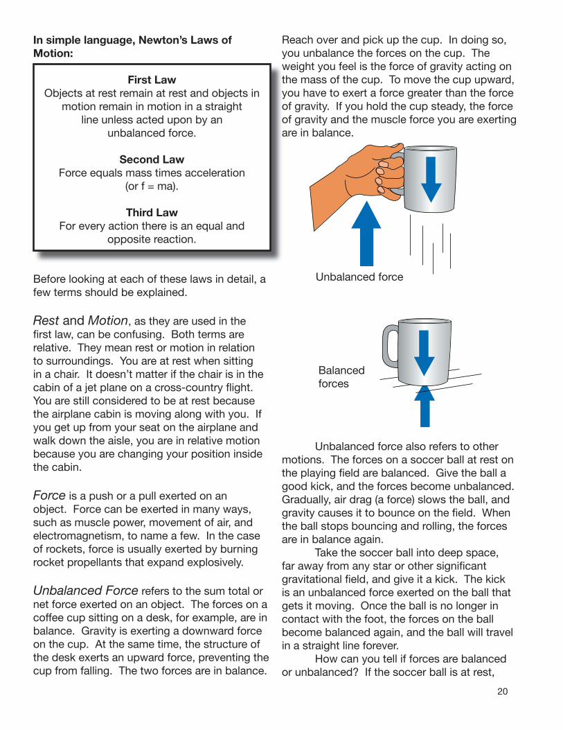
Unbalanced Force refers to the sum total or net force exerted on an object. The forces on a coffee cup sitting on a desk, for example, are in balance. Gravity is exerting a downward force on the cup. At the same time, the structure of the desk exerts an upward force, preventing the cup from falling. The two forces are in balance.
Reach over and pick up the cup. In doing so, you unbalance the forces on the cup. The weight you feel is the force of gravity acting on the mass of the cup. To move the cup upward, you have to exert a force greater than the force of gravity. If you hold the cup steady, the force of gravity and the muscle force you are exerting are in balance.
Unbalanced force
Balancedforces
Unbalanced force also refers to other motions. The forces on a soccer ball at rest on the playing fi eld are balanced. Give the ball a good kick, and the forces become unbalanced. Gradually, air drag (a force) slows the ball, and gravity causes it to bounce on the fi eld. When the ball stops bouncing and rolling, the forces are in balance again. Take the soccer ball into deep space, far away from any star or other signifi cant gravitational fi eld, and give it a kick. The kick is an unbalanced force exerted on the ball that gets it moving. Once the ball is no longer in contact with the foot, the forces on the ball become balanced again, and the ball will travel in a straight line forever. How can you tell if forces are balanced or unbalanced? If the soccer ball is at rest,

21
the forces are balanced. If the ball is moving at a constant speed and in a straight line, the forces are balanced. If the ball is accelerating or changing its direction, the forces are unbalanced.
Mass is the amount of matter contained in an object. The object does not have to be solid. It could be the amount of air contained in a balloon or the amount of water in a glass. The important thing about mass is that unless you alter it in some way, it remains the same whether the object is on Earth, in Earth orbit, or on the Moon. Mass just refers to the quantity of matter contained in the object. (Mass and weight are often confused. They are not the same thing. Weight is a force and is the product of mass times the acceleration of gravity.)
Acceleration relates to motion. It means a change in motion. Usually, change refers to increasing speed, like what occurs when you step on the accelerator pedal of a car. Acceleration also means changing direction.
Balanced Force
Unbalanced Force
Top view of two riders on a carousel. The carousel platform exerts unbalanced forces on the riders, preventing them from going in straight lines. Instead, the platform continually accelerates the riders in a counterclockwise direction.
This is what happens on a carousel. Even though the carousel is turning at a constant rate, the continual change in direction of the horses and riders (circular motion) is an acceleration.
Action is the result of a force. A cannon fires, and the cannon ball flies through the air. The movement of the cannon ball is an action. Release air from an inflated balloon. The air shoots out the nozzle. That is also an action. Step off a boat onto a pier. That, too, is an action.
Reaction is related to action. When the cannon fires, and the cannon ball flies through the air, the cannon itself recoils backward. That is a reaction. When the air rushes out of the balloon, the balloon shoots the other way, another reaction. Stepping off a boat onto to a pier causes a reaction. Unless the boat is held in some way, it moves in the opposite direction. (Note: The boat example is a great demonstration of the action/reaction principle, providing you are not the one stepping off the boat!)
Newton’s First LawThis law is sometimes referred to as Galileo’s law of inertia because Galileo discovered the principle of inertia. This law simply points

22
out that an object at rest, such as a rocket on a launch pad, needs the exertion of an unbalanced force to cause it to lift off. The amount of the thrust (force) produced by the rocket engines has to be greater than the force of gravity holding it down. As long as the thrust of the engines continues, the rocket accelerates. When the rocket runs out of propellant, the forces become unbalanced again. This time, gravity takes over and causes the rocket to fall back to Earth. Following its “landing,” the rocket is at rest again, and the forces are in balance. There is one very interesting part of this law that has enormous implications for spaceflight. When a rocket reaches space, atmospheric drag (friction) is greatly reduced or eliminated. Within the atmosphere, drag is an important unbalancing force. That force is virtually absent in space. A rocket traveling away from Earth at a speed greater than 11.186 kilometers per second (6.95 miles per second) or 40,270 kilometers per hour (25,023 mph) will eventually escape Earth’s gravity. It will slow down, but Earth’s gravity will never slow it down enough to cause it to fall back to Earth. Ultimately, the rocket (actually its payload) will travel to the stars. No additional rocket thrust will be needed. Its inertia will cause it to continue to travel outward. Four spacecraft are actually doing that as you read this. Pioneers 10 and 11 and Voyagers 1 and 2 are on journeys to the stars!
Newton’s Third Law(It is useful to jump to the third law and come back to the second law later.) This is the law of motion with which many people are familiar. It is the principle of action and reaction. In the case of rockets, the action is the force produced by the expulsion of gas, smoke, and flames from the nozzle end of a rocket engine. The reaction force propels the rocket in the opposite direction. When a rocket lifts off, the combustion products from the burning propellants accelerate rapidly out of the engine. The rocket, on the other hand, slowly accelerates
skyward. It would appear that something is wrong here if the action and reaction are supposed to be equal. They are equal, but the mass of the gas, smoke, and flames being propelled by the engine is much less than the mass of the rocket being propelled in the opposite direction. Even though the force is equal on both, the effects are different. Newton’s first law, the law of inertia, explains why. The law states that it takes a force to change the motion of an object. The greater the mass, the greater the force required to move it.
Newton’s Second Law The second law relates force, acceleration, and mass. The law is often written as the equation:
f = m a
The force or thrust produced by a rocket engine is directly proportional to the mass of the gas and particles produced by burning rocket propellant times the acceleration of those combustion products out the back of the engine. This law only applies to what is actually traveling out of the engine at the moment and not the mass of the rocket propellant contained in the rocket that will be consumed later. The implication of this law for rocketry is that the more propellant (m) you consume at any moment and the greater the acceleration (a) of the combustion products out of the nozzle, the greater the thrust (f).
AC
TC
REA
NIO
TION

23
A Taste of Real Rocket ScienceNaturally, launching rockets into space is more complicated than Newton’s laws of motion imply. Designing rockets that can actually lift off Earth and reach orbital velocities or interplanetary space is an extremely complicated process. Newton’s laws are the beginning, but many other things come into play. For example, outside or ambient air pressure plays an important role while the rocket is still in the atmosphere. The internal pressure produced by burning rocket propellants inside the rocket engine combustionchamber has to be greater than the outside pressure to escape through the engine nozzle. In a sense, the outside air is like a cork in the engine. It takes some of the pressure generated inside the engine just to exceed the ambient outside pressure. Consequently, the velocity of combustion products passing through the opening or throat of the nozzle is reduced. The good news is that as the rocket climbs into space, the ambient pressure becomes less and less as the atmosphere thinsand the engine thrust increases. Another important factor is the changing mass of the rocket. As the rocket is gaining thrust as it accelerates upward due to outside pressure changes, it is also getting a boost due to its changing mass. Every bit of rocket propellant burned has mass. As the combustion products are ejected by the engine,the total mass of the vehicle lessens. As it doesits inertia, or resistance to change in motion, becomes less. As a result, upward accelerationof the rocket increases.
In practical terms, Newton’s second law can berewritten as this:
f = m exitV exit + (p exit - p ambient)A exit
(“A” refers to the area of the engine throat.)
When the rocket reaches space, and the exit pressure minus the ambient pressure becomes zero, the equation becomes:
f = mexitVexit
In real rocket science, many other things also come into play.
• Even with a low acceleration, the rocket will gain speed over time because acceleration accumulates.
• Not all rocket propellants are alike. Some produce much greater thrust than others
because of their burning rate and mass. It would seem obvious that rocket scientists would always choose the more energetic propellants. Not so. Each choice a rocket scientist makes comes with a cost. Liquid hydrogen and liquid oxygen are very energetic when burned, but they both have to be kept chilled to very low temperatures. Furthermore, their mass is low, and very big tanks are needed to contain enough propellant to do the job.
In Conclusion...Newton’s laws of motion explain just about everything you need to know to become a rocket scientist. However, knowing the laws is not enough. You have to know how to apply them, such as:
- How can you create enough thrust to exceed the weight of the rocket?
- What structural materials and propellant combinations should you use?
- How big will the rocket have to be? - How can you make the rocket go where
you want it to? - How can you bring it back to Earth
safely?

24
Applying Newton’s Laws
The next step in becoming a rocket scientist is to apply rocket science and mathematics to the design and construction of actual rockets. There are many tricks of the trade for maximizing thrust and reducing rocket mass. Each of these tricks is an application of one or more of Newton’s laws. Although there are many different kinds of rockets, the same laws apply to all. Rockets are generally classified as either solid or liquid. They produce thrust by burning propellants and expelling the combustion products out of the engine. Propellants are simply a combination of fuel and oxidizer. The oxidizer for solid propellants is a chemical containing oxygen. For example, gunpowder, used in the engines of model rockets, contains potassium nitrate (KNO3). Potassium nitrate provides the oxygen needed for the other gunpowder chemicals to burn rapidly. The oxidizer for liquid rockets is usually pure oxygen chilled to 90 K (-183oC or -297.3oF) so that it condenses into liquid oxygen (LOX). The propellants for rockets are held in tanks or within cases. This is both an advantage and a disadvantage. Because they carry their propellants (oxygen onboard), rockets can work in space. No other presently available vehicle can do that. A jet engine cannot function in space because it is an “air-breather.” Although jets and rockets both employ Newton’s law of action and reaction, the jet needs to draw in air from the atmosphere to burn its fuel. This limits the altitude of a jet plane.
Solid Propellant Rockets The first true rockets, “fire arrows” invented by the Chinese, employed solid propellants. An early form of gunpowder was packed into a cylinder closed off at one end. On the other end was an opening. When the gunpowder was ignited, it burned very quickly and created great quantities of gas and other combustion products that rushed out of the hole. This produced thrust. Flight control was accomplished by attaching a long stick to the rocket to create drag as the rocket sailed
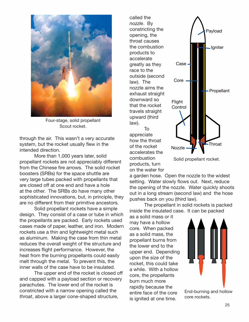
25
through the air. This wasn’t a very accurate system, but the rocket usually flew in the intended direction. More than 1,000 years later, solid propellant rockets are not appreciably different from the Chinese fire arrows. The solid rocket boosters (SRBs) for the space shuttle are very large tubes packed with propellants that are closed off at one end and have a hole at the other. The SRBs do have many other sophisticated innovations, but, in principle, they are no different from their primitive ancestors. Solid propellant rockets have a simple design. They consist of a case or tube in which the propellants are packed. Early rockets used cases made of paper, leather, and iron. Modern rockets use a thin and lightweight metal such as aluminum. Making the case from thin metal reduces the overall weight of the structure and increases flight performance. However, the heat from the burning propellants could easily melt through the metal. To prevent this, the inner walls of the case have to be insulated. The upper end of the rocket is closed off and capped with a payload section or recovery parachutes. The lower end of the rocket is constricted with a narrow opening called the throat, above a larger cone-shaped structure,
called the nozzle. By constricting the opening, the throat causes the combustion products to accelerate greatly as they race to the outside (second law). The nozzle aims the exhaust straight downward so that the rocket travels straight upward (third law). To appreciate how the throat of the rocket accelerates the combustion products, turn on the water for a garden hose. Open the nozzle to the widest setting. Water slowly flows out. Next, reduce the opening of the nozzle. Water quickly shoots out in a long stream (second law) and the hose pushes back on you (third law). The propellant in solid rockets is packed inside the insulated case. It can be packed as a solid mass or it may have a hollow core. When packed as a solid mass, the propellant burns from the lower end to the upper end. Depending upon the size of the rocket, this could take a while. With a hollow core, the propellants burn much more rapidly because the entire face of the core is ignited at one time.
Four-stage, solid propellant Scout rocket.
Payload
Igniter
Case
Core
Propellant
FlightControl
ThroatNozzle
Solid propellant rocket.
End-burning and hollow core rockets.

26
Rather than burning from one end to the other, the propellant burns from the core outward, towards the case. The advantage of a hollow core is that the propellant mass burns faster, increasing thrust (second law). To make solid rockets even more powerful, the core doesn’t have to be round. It can have other shapes that increase the surface area available for burning. The upper ends of the space shuttle SRBs have star-shaped cores. When ignited, the large surface area of the star points boost liftoff thrust. In about one minute, however, the points burn off, and the thrust diminishes somewhat. This is done on purpose because the space shuttle begins accelerating through the sound barrier. Passing through causes vibrations that are diminished by the temporary thrust reduction of the SRBs (second law). Solid propellant rockets have two other major systems at work. One is the control system, which will be discussed later. The other is the igniter. The Chinese fire arrows were ignited with fuses. This was a dangerous practice because the fuse could burn too quickly and not give the rocketeer time to get out of the way. Fuses were used for centuries until they were replaced by electric ignition. With an electric system, a wire with high resistance heats and ignites the propellant. The space shuttle’s SRBs (and soon the Ares version of the SRBs) add an extra component to the ignition system. A small rocket motor is mounted inside the upper end of the core. When it ignites, it shoots a long tongue of flame down the core to ignite the entire surface at once. This causes the SRBs to reach full thrust in less than one second.
Liquid Propellant RocketsLiquid propellant rockets are an invention of the twentieth century. They are far more complex than solid rockets. Generally, a liquid rocket has two large tanks within its body. One tank contains a fuel, such as kerosene or liquid hydrogen. The other tank contains liquid oxygen.
Payload
Hydrogen
Oxygen
Pumps
CombustionChamber
FlightControl
ThroatNozzle
Liquid propellant rocket
RS-68 Liquid propellant engine test firing.
When the liquid rocket engine is fired, high-speed pumps force the propellants into a cylindrical or spherical combustion chamber. The fuel and oxidizer mix as they are sprayed into the chamber. There they ignite, creating huge quantities of combustion products that shoot through the throat and are focused downward by the nozzle. (Remember how the laws control this!) Liquid propellant engines have a number of advantages over solid propellant engines. A wider array of propellant combinations are available for different applications. Some of these require an ignition system and others simply ignite on contact. Monomylmethylhydrozene (fuel) and nitrogen tetroxide (oxidizer) ignite spontaneously. These are called hypergolic propellants. With hypergolic propellants, a rocket engine does not need an ignition system. Hypergolic propellants are great for attitude control rockets like those that will be arrayed around the Orion service

27
module and the ascent stage of the Altair lunar lander. Another advantage of liquid propellants is that they can be controlled. Adjusting their flow into the combustion chamber adjusts the amount of thrust produced. Furthermore, liquid engines can be stopped and restarted later. It is very difficult to stop a solid propellant rocket once it is started, and thrust control is limited. Naturally, with any technology, there is a price to pay. The engine of a liquid propellant rocket is very complex and subject to failure. It also has more structural mass than comparable solid propellant rockets. One method for mass reduction is to use thin, lightweight metal for the nozzle. Normally, the nozzle is very thick and heavy, to prevent it from eroding away in the high-temperature streams of exhaust gases. A thin-wall nozzle needs a cooling
system. Small tubes lace the walls and carry liquid hydrogen. Hydrogen becomes a liquid at 20.27 K (-252.87oC or -423.17oF). The super cold hydrogen absorbs the heat from the gas stream and protects the walls of the nozzle. The hydrogen, now heated, is then injected into the combustion chamber. With this system, the engine has less mass and produces greater thrust (second law again!).
Liquid propellant Delta rocketcarrying the Dawn spacecraft.
Controlling FlightNewton’s third law gets a workout in the control systems for rockets. Launch rods for old rockets were ineffective. Military rockets were launched by the thousands so that at least a few would hit their targets. Accuracy improved when small vanes were added to the exhaust stream. The vanes imparted stability by causing the rockets to spiral like bullets. Another technique was to add fins, like the feathers on an arrow, to the lower end of the rocket case. As long as a rocket flies “straight as an arrow,” the fins provide little drag or friction with the air. However, if the engine end of the rocket begins “fishtailing,” drag increases greatly. The air stream strikes the fin, and the fin directs the stream to the side. The lower end of the rocket moves the opposite way and corrects the fishtailing (Newton’s third law). Fins are used extensively with model rockets and small missiles. Rocket fins on model rockets are a passive system for flight control. They remain fixed and do their job if the rocket starts going astray. Robert Goddard took fins a giant step forward by turning them into an active system. Goddard’s fins could be made smaller (and lighter!) because they were not fixed. Even a slight straying from the planned course would cause the fins to react and tilt slightly in the appropriate direction. The heart of Goddard’s control system, later used in the V2 and other advanced rockets, was a gyroscope. Gyroscopes, which are a kind of top, spin at high speeds and become stable due to their inertia (first law). In other words, the axis of the gyroscope points in one direction. If the rocket veers from course, the movement acts on the alignment of the

28
gyroscope, and a linkage or an electrical system connected to the gyroscope transmits the appropriate corrections to the movable rocket fins. You can get an idea of the effectiveness of movable fins with a simple demonstration. Balance a long stick on the palm of your hand. If the stick starts tilting to the right, you automatically move your hand to the right to straighten up the stick. Movable fins do the same thing. The rocket starts tilting to the right. The leading edge of the fins bend to the right. This causes the air stream to be deflected to the left. The lower end of the rocket moves to the right, and the rocket is back on course. Naturally, some fins are more
complicated than just described. Depending upon the rocket design, the entire fin may not move. Instead, a lower flap might be the controllable part of the fin (kind of like a rudder). Very small movable fins might also be placed towards the nose of the rocket. These are called canards, and they permit rapid and extreme control maneuvers for air-to-air military missiles. Small fins, called vanes, may be placed within the exhaust stream of the engine. When a vane tilts, it directs part of the exhaust
to one side or another. The lower end of the rocket responds by moving the other way. All of these fin styles are examples of Newton’s third law in action. Another way the third law is applied for controlling flight is through gimballed engine nozzles. Gimballed means the nozzle can tilt indifferent directions. Movements of the nozzle can steer the rocket on a new course or make course corrections. The solid rocket boostersused for the Ares I and V first stages will use gimballing for control.
NewCourse
NewCourse
Air flow deflected bytilting fin
Gimbalchangesdirection of thrust
Controlling MassThe total mass of a rocket has a major influence on its performance. If the rocket has a greater mass than the engines are capable of lifting, the rocket remains stuck on Earth (first law). The lighter the rocket, the better. However, since the rocket must carry all of its propellants (there aren’t any filling stations in space —YET!), a big part of the rocket’s mass has to be its propellants. The mass of the propellants burned is a big part of thrust (second law). Mass savings have to come from elsewhere — the rocket structure. Engineering rocket tanks out of lightweight materials strengthened by ribs is a great way of saving mass. Chilling hydrogen and oxygen propellants until they liquefy reduces their total volume. That means smaller, less massive tanks can be used. Gimbaling engines for control means that heavy fins can be eliminated. When designing new rockets, rocket scientists (and engineers) concern themselves with mass fraction. Mass fraction is a simple inverse mathematical relationship between the mass of the propellants of the rocket and the total mass of the rocket. Although there is wiggle room in this equation, the most efficient rockets have mass fractions of about 0.91. That means that of the total rocket,
mass (propellant)MF =
mass (total rocket)
29
propellant accounts for 91% of its mass. The rocket structure and payload comprises the other 9%. Since you need the mass of the propellants, efforts on saving mass are primarily focused on structure and payload. One simple but old trick is staging. Begin with a large rocket, stack a smaller one on top of it, stack a still smaller rocket on top of the second one, and then the payload on top of the third rocket. The large rocket lifts its own mass and the mass of the other two. When the large rocket (fi rst stage) is empty, it drops off. The second rocket (second stage) fi res and accelerates itself and the third stage with its payload to higher speeds and altitudes. When it is empty, the second stage is dropped, and the third stage fi nishes the job of delivering the payload. By staging, the mass of the rocket is reduced in fl ight, making the upper stages more effi cient in doing their jobs.
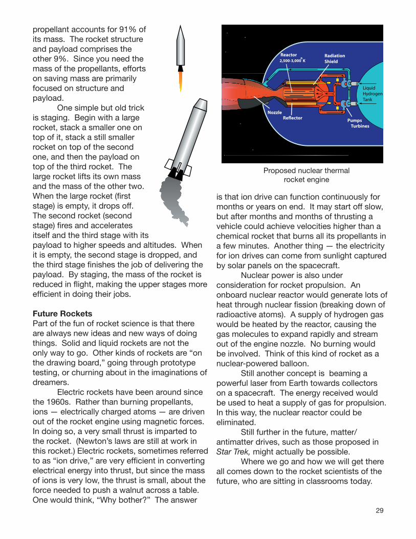
Future RocketsPart of the fun of rocket science is that there are always new ideas and new ways of doing things. Solid and liquid rockets are not the only way to go. Other kinds of rockets are “on the drawing board,” going through prototype testing, or churning about in the imaginations of dreamers. Electric rockets have been around since the 1960s. Rather than burning propellants, ions — electrically charged atoms — are driven out of the rocket engine using magnetic forces. In doing so, a very small thrust is imparted to the rocket. (Newton’s laws are still at work in this rocket.) Electric rockets, sometimes referred to as “ion drive,” are very effi cient in converting electrical energy into thrust, but since the mass of ions is very low, the thrust is small, about the force needed to push a walnut across a table. One would think, “Why bother?” The answer
is that ion drive can function continuously for months or years on end. It may start off slow, but after months and months of thrusting a vehicle could achieve velocities higher than a chemical rocket that burns all its propellants in a few minutes. Another thing — the electricity for ion drives can come from sunlight captured by solar panels on the spacecraft. Nuclear power is also under consideration for rocket propulsion. An onboard nuclear reactor would generate lots of heat through nuclear fi ssion (breaking down of radioactive atoms). A supply of hydrogen gas would be heated by the reactor, causing the gas molecules to expand rapidly and stream out of the engine nozzle. No burning would be involved. Think of this kind of rocket as a nuclear-powered balloon. Still another concept is beaming a powerful laser from Earth towards collectors on a spacecraft. The energy received would be used to heat a supply of gas for propulsion. In this way, the nuclear reactor could be eliminated. Still further in the future, matter/antimatter drives, such as those proposed in Star Trek, might actually be possible. Where we go and how we will get there all comes down to the rocket scientists of the future, who are sitting in classrooms today.
NozzleReflector
RadiationShield
PumpsTurbines
Reactor
LiquidHydrogenTank
2,500-3,000 Ko
Proposed nuclear thermal rocket engine

30
Rocket Activities
There are few classroom topics that generate as much excitement as rockets. The scientific, technological, engineering, and mathematical (STEM) foundations of rocketry provide exciting classroom opportunities for authentic hands-on, minds-on experimentation. The activities and demonstrations that follow are suitable for students at many grade levels. For the most part, material and tool requirements are simple, but a few of the bigger projects require launch platforms that need to be constructed or purchased in advance. Although purchasing platforms from school science catalogs and specialty companies is an option, constructing your own is a learning process in which you can involve your students. Minimal proficiency with tools (saw, screw driver) is required. Detailed instructions (with lots of illustrations!) are provided. As you review the activities you will notice that each supports state and national educational standards for science, technology, and mathematics. A matrix identifying specific national standards and recommended grade levels follow on the next two pages. You may “cherry-pick” activities, but linking several or using all of the activities will provide your students with a memorable and beneficial STEM unit and turn your students into “rocket scientists.” You Are Go For Launch!
A Note about MeasurementWhere possible, all measurements used in the activities are metric. However, English units are often employed when constructing devices because most materials and parts are sized with English measures.
31
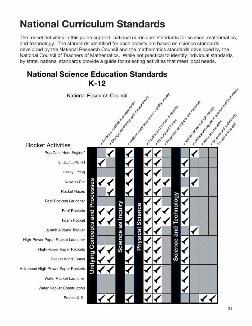
National Curriculum StandardsThe rocket activities in this guide support national curriculum standards for science, mathematics, and technology. The standards identified for each activity are based on science standards developed by the National Research Council and the mathematics standards developed by the National Council of Teachers of Mathematics. While not practical to identify individual standards by state, national standards provide a guide for selecting activities that meet local needs.
• E
viden
ce, m
odel
s an
d ex
plan
atio
n
• C
hang
e, c
onst
ancy
, and
mea
sure
men
t
• A
bilit
ies
nece
ssar
y to
do
scie
ntific
inqu
iry
• P
ositi
on a
nd m
otio
n of
obj
ects
• M
otio
ns a
nd fo
rces
• P
rope
rties
of o
bjec
ts a
nd m
ater
ials
• A
bilit
ies
of te
chno
logi
c de
sign
• U
nder
stan
ding
abo
ut s
cien
ce a
nd te
chno
logy
• R
isks
and
bene
fits
• S
cien
ce a
nd te
chno
logy
in lo
cal c
halle
nges
Pop Can “Hero Engine”
3...2...1...PUFF!
Heavy Lifting
Newton Car
Rocket Races
Pop! Rockets Launcher
Pop! Rockets
Foam Rocket
Launch Altitude Tracker
High-Power Paper Rocket Launcher
High-Power Paper Rockets
Rocket Wind Tunnel
Advanced High-Power Paper Rockets
Water Rocket Launcher
Water Rocket Construction
Project X-51
National Science Education StandardsK-12
National Research Council
Rocket ActivitiesP
hysi
cal S
cien
ce
Sci
ence
and
Tec
hno
log
y
Sci
ence
as
Inq
uiry
Uni
fyin
g C
onc
epts
and
Pro
cess
es

32
Principles and Standards for School MathematicsPre K - 12
National Council of Teachers of Mathematics
• N
umbe
r and
Ope
ratio
ns
• Alge
bra
• G
eom
etry
•
Mea
sure
men
t
• D
ata A
nalys
is an
d Pro
babil
ity
• P
roble
m S
olving
• R
easo
ning
and
Proof
• Com
mun
icatio
n
• Con
nect
ions
• Rep
rese
ntat
ions
Pop Can “Hero Engine”
3...2...1...PUFF!
Heavy Lifting
Newton Car
Rocket Races
Pop! Rockets Launcher
Pop! Rockets
Foam Rocket
Launch Altitude Tracker
High-Power Paper Rocket Launcher
High-Power Paper Rockets
Rocket Wind Tunnel
Advanced High-Power Paper Rockets
Water Rocket Launcher
Water Rocket Construction
Project X-51
• N
umbe
r and
Ope
ratio
ns
• Alge
bra
• G
eom
etry
•
Mea
sure
men
t
• D
ata A
nalys
is an
d Pro
babil
ity
• P
roble
m S
olving
• R
easo
ning
and
Proof
• Com
mun
icatio
n
• Con
nect
ions
• Rep
rese
ntat
ions
Co
nten
t S
tand
ard
s
Pro
cess
Sta
ndar
ds
Rocket Activities
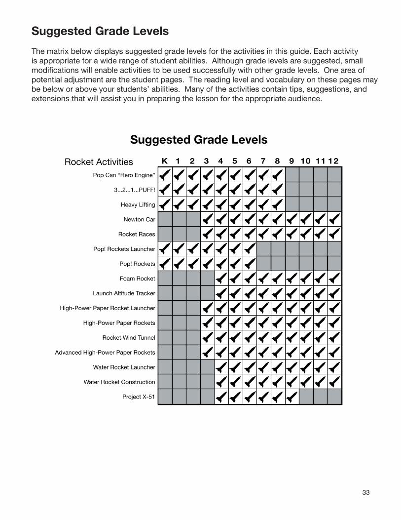
33
K 1 2 3 4 5 6 7 8 9 10 11 12
Pop Can “Hero Engine”
3...2...1...PUFF!
Heavy Lifting
Newton Car
Rocket Races
Pop! Rockets Launcher
Pop! Rockets
Foam Rocket
Launch Altitude Tracker
High-Power Paper Rocket Launcher
High-Power Paper Rockets
Rocket Wind Tunnel
Advanced High-Power Paper Rockets
Water Rocket Launcher
Water Rocket Construction
Project X-51
Rocket Activities
Suggested Grade Levels
The matrix below displays suggested grade levels for the activities in this guide. Each activity is appropriate for a wide range of student abilities. Although grade levels are suggested, small modifications will enable activities to be used successfully with other grade levels. One area of potential adjustment are the student pages. The reading level and vocabulary on these pages may be below or above your students’ abilities. Many of the activities contain tips, suggestions, and extensions that will assist you in preparing the lesson for the appropriate audience.
Suggested Grade Levels

34
Rocket Activity
Pop Can “Hero Engine”
ObjectiveTo investigate Newton’s third law of motion using thrust produced by falling water.
DescriptionSmall student teams will construct water-propelled engines out of soft drink cans and investigate ways to increase the action-reaction thrust produced by water shooting out of holes punched in the can sides.
COLA
National Science Content StandardsUnifying Concepts and Processes • Change, constancy, and measurementScience as Inquiry • Abilities necessary to do scientifi c
inquiryPhysical Science • Position and motion of objects • Motions and forcesScience and Technology
• Understanding about science and technology
National Mathematics Content Standards• Number and Operations• Measurement• Data Analysis and Probability
National Mathematics Process Standards• Reasoning and Proof• Communication• Connections• Representations
Materials4 empty aluminum soft drink cans per
team, with pull tabs intact Carpenter’s nails of different sizes ( 6,12,
16D, etc.)String (about 50 cm)Water tub (large plastic storage tub, small
kiddy pool, sink, etc.)WaterTowelsRulersStickers or bright permanent marker
ManagementDivide your students into small groups. Set up one or more water tubs around your classroom and fi ll the tubs with about 20 cm of water. Have no more than one or two teams test their engines at one time. Discuss the importance of keeping the water in the tubs. When engines are fi lled, they should not be raised any higher than the rim of the tub. This will keep water coming out of the holes from falling on the surrounding fl oor. Be sure to recycle the cans at the conclusion of the activity.
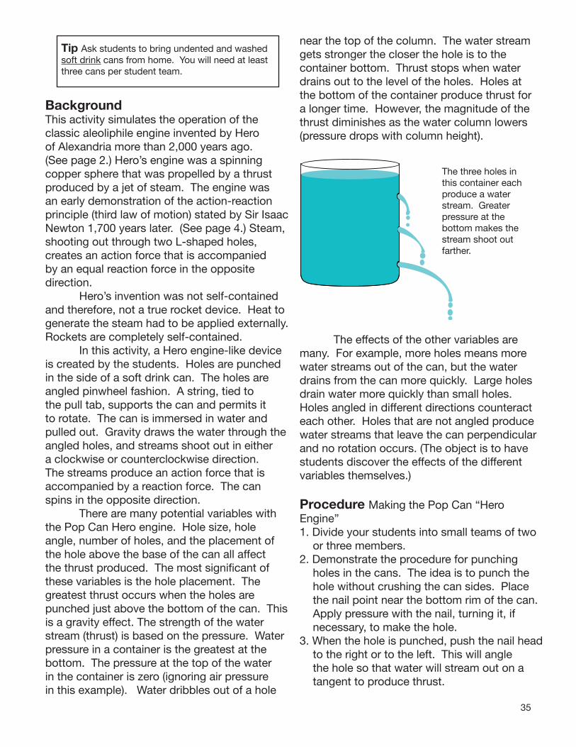
35
Tip Ask students to bring undented and washed soft drink cans from home. You will need at least three cans per student team.
BackgroundThis activity simulates the operation of the classic aleoliphile engine invented by Hero of Alexandria more than 2,000 years ago. (See page 2.) Hero’s engine was a spinning copper sphere that was propelled by a thrust produced by a jet of steam. The engine was an early demonstration of the action-reaction principle (third law of motion) stated by Sir Isaac Newton 1,700 years later. (See page 4.) Steam, shooting out through two L-shaped holes, creates an action force that is accompanied by an equal reaction force in the opposite direction. Hero’s invention was not self-contained and therefore, not a true rocket device. Heat to generate the steam had to be applied externally. Rockets are completely self-contained. In this activity, a Hero engine-like device is created by the students. Holes are punched in the side of a soft drink can. The holes are angled pinwheel fashion. A string, tied to the pull tab, supports the can and permits it to rotate. The can is immersed in water and pulled out. Gravity draws the water through the angled holes, and streams shoot out in either a clockwise or counterclockwise direction. The streams produce an action force that is accompanied by a reaction force. The can spins in the opposite direction. There are many potential variables with the Pop Can Hero engine. Hole size, hole angle, number of holes, and the placement of the hole above the base of the can all affect the thrust produced. The most significant of these variables is the hole placement. The greatest thrust occurs when the holes are punched just above the bottom of the can. This is a gravity effect. The strength of the water stream (thrust) is based on the pressure. Water pressure in a container is the greatest at the bottom. The pressure at the top of the water in the container is zero (ignoring air pressure in this example). Water dribbles out of a hole
near the top of the column. The water stream gets stronger the closer the hole is to the container bottom. Thrust stops when water drains out to the level of the holes. Holes at the bottom of the container produce thrust for a longer time. However, the magnitude of the thrust diminishes as the water column lowers (pressure drops with column height).
The three holes in this container each produce a water stream. Greater pressure at the bottom makes the stream shoot out farther.
The effects of the other variables are many. For example, more holes means more water streams out of the can, but the water drains from the can more quickly. Large holes drain water more quickly than small holes. Holes angled in different directions counteract each other. Holes that are not angled produce water streams that leave the can perpendicular and no rotation occurs. (The object is to have students discover the effects of the different variables themselves.)
Procedure Making the Pop Can “Hero Engine”1. Divide your students into small teams of two
or three members. 2. Demonstrate the procedure for punching
holes in the cans. The idea is to punch the hole without crushing the can sides. Place the nail point near the bottom rim of the can. Apply pressure with the nail, turning it, if necessary, to make the hole.
3. When the hole is punched, push the nail head to the right or to the left. This will angle the hole so that water will stream out on a tangent to produce thrust.
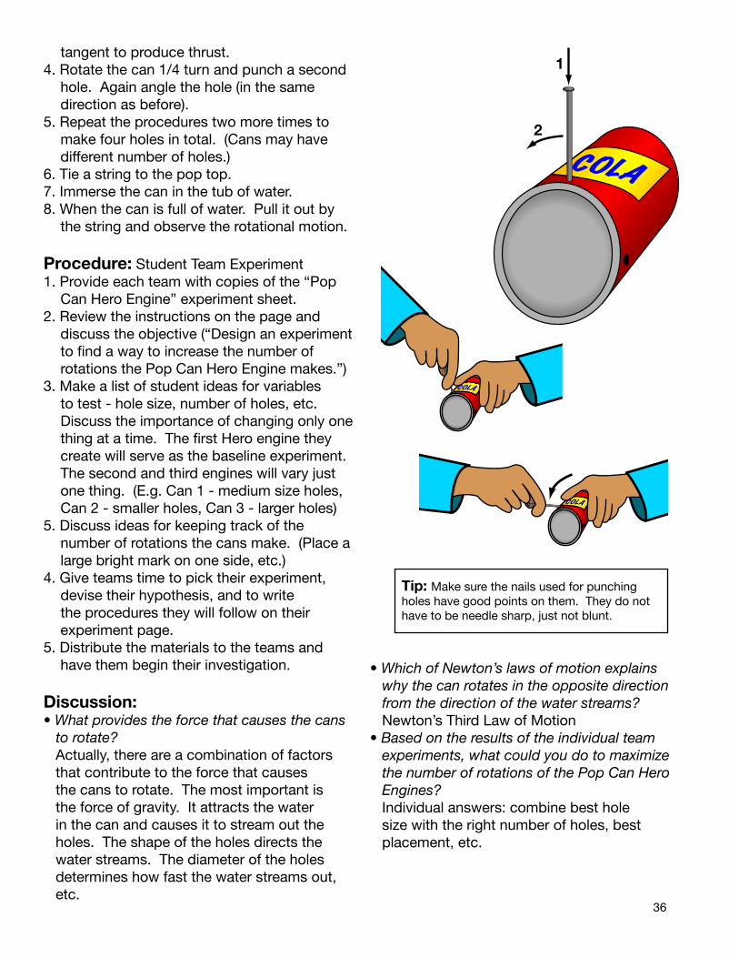
36
tangent to produce thrust.4. Rotate the can 1/4 turn and punch a second
hole. Again angle the hole (in the same direction as before).
5. Repeat the procedures two more times to make four holes in total. (Cans may have different number of holes.)
6. Tie a string to the pop top.7. Immerse the can in the tub of water.8. When the can is full of water. Pull it out by
the string and observe the rotational motion.
Procedure: Student Team Experiment1. Provide each team with copies of the “Pop
Can Hero Engine” experiment sheet.2. Review the instructions on the page and
discuss the objective (“Design an experiment to find a way to increase the number of rotations the Pop Can Hero Engine makes.”)
3. Make a list of student ideas for variables to test - hole size, number of holes, etc. Discuss the importance of changing only one thing at a time. The first Hero engine they create will serve as the baseline experiment. The second and third engines will vary just one thing. (E.g. Can 1 - medium size holes, Can 2 - smaller holes, Can 3 - larger holes)
5. Discuss ideas for keeping track of the number of rotations the cans make. (Place a large bright mark on one side, etc.)
4. Give teams time to pick their experiment, devise their hypothesis, and to write the procedures they will follow on their experiment page.
5. Distribute the materials to the teams and have them begin their investigation.
Discussion:• What provides the force that causes the cans
to rotate? Actually, there are a combination of factors
that contribute to the force that causes the cans to rotate. The most important is the force of gravity. It attracts the water in the can and causes it to stream out the holes. The shape of the holes directs the water streams. The diameter of the holes determines how fast the water streams out, etc.
• Which of Newton’s laws of motion explains why the can rotates in the opposite direction from the direction of the water streams?
Newton’s Third Law of Motion• Based on the results of the individual team
experiments, what could you do to maximize the number of rotations of the Pop Can Hero Engines?
Individual answers: combine best hole size with the right number of holes, best placement, etc.
Tip: Make sure the nails used for punching holes have good points on them. They do not have to be needle sharp, just not blunt.
COLA
1
2
COLA
COLA
COLA
COLA

37
Assessment• Ask teams to state their experiment
hypotheses, explain their procedures, and present their results. Make a list of the different ways one can increase the number of rotations the Hero engine makes.
• Have teams submit their completed data sheet with their written conclusion based on their results.
Extensions• Construct an actual steam-powered hero
engine and use it as a demonstration device. Although not diffi cult to construct, the engine will require some basic construction skills, principally soldering. You will need the following materials:
- Copper toilet tank fl oat (available from plumbing supply stores and from on-line plumbing supply stores - search “copper toilet tank fl oats.”
- 12” copper tube, 3/16” diameter (from hobby shops)
- Thumbscrew to fi t threads for fl oat arm attachment
- Metal fi le- 3/16” drill- solder- propane torch- pliers- string- water- eye protection
1. File a notch in the center of the tube. Do not fi le all the way through. In Instruction 3, the tube will be inserted completely through the sphere. This supports the tube while it is being soldered. (See diagram to the right.)
2. Drill 3/16th” holes through opposite sides of the fl oat just above the “equator” joint.
3. Insert the tube through the holes. Lightly heat the place where the tubes contact the sphere. Touch solder to the contact point to seal the tube to the fl oat.
4. Apply heat to soften the opposite ends of the tube until they bend easily. Using pliers to
grasp the ends, bend the tube ends into an L shape. Be careful not to overheat or bend too forcefully, or the tube may fl atten on the bend.
5. Drill through the center of the threads for the attachment point for the fl oat arm. This will open a water-fi lling hole into the fl oat.
6. Drill a hole through the fl at side of the thumb screw to permit tying of the string.
7. Pour about 30 milliliters of water (about 1 tablespoon) into the fl oat through the fi lling hole.
8. Thread the thumbscrew into the hole and attach the string.
9. Suspend the engine from above and gently heat the bottom of the engine with a torch. Be sure to wear eye protection. When the water boils, steam will be produced that will jet out of the two nozzles and propel the engine.
Filing produces an opening in the tube through which the steam can pass.
Tip Before using your steam Hero engine, confi rm the tubes are not blocked by blowing through them. If air comes out the opposite tube, the engine is safe to use.
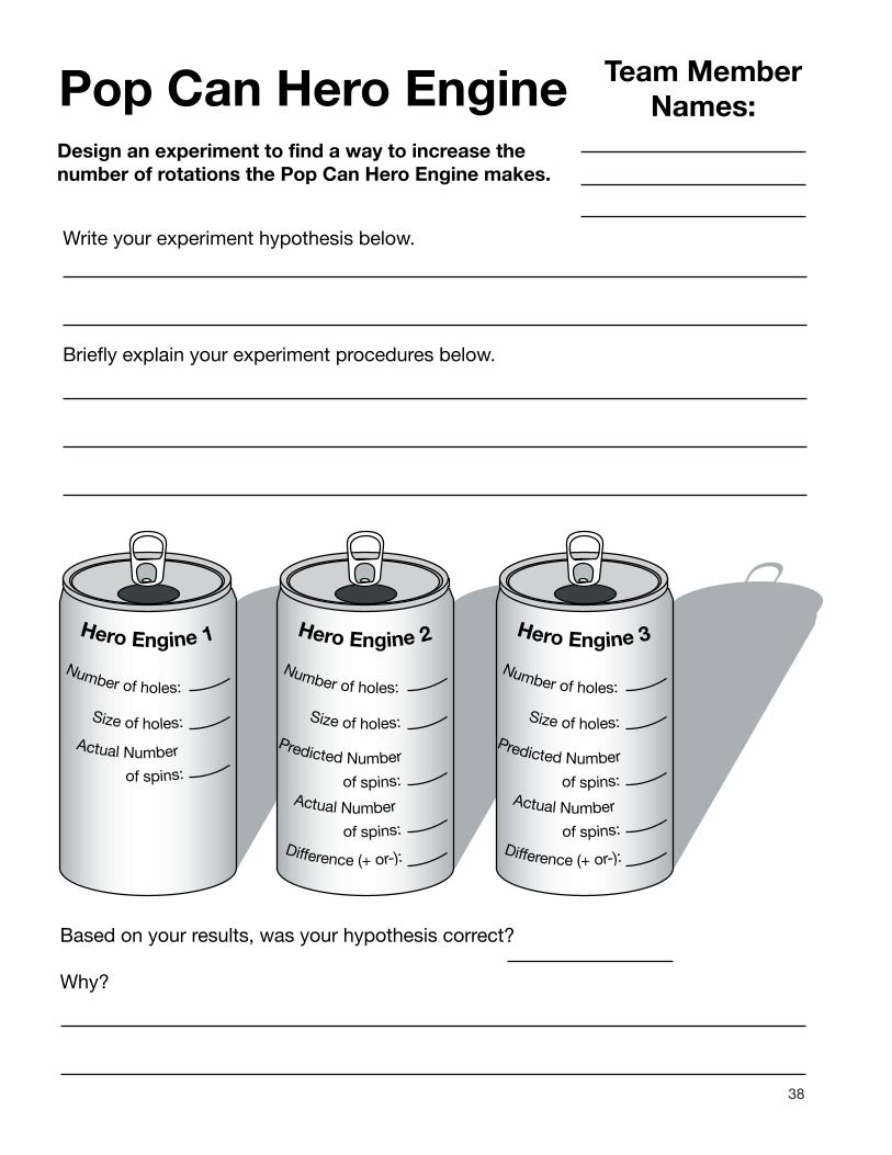
38
Pop Can Hero EngineDesign an experiment to find a way to increase thenumber of rotations the Pop Can Hero Engine makes.
Team MemberNames:
Write your experiment hypothesis below.
Briefly explain your experiment procedures below.
Hero Engine 1
Actual Number
of spins:
Number of holes:
Size of holes:
Hero Engine 2
Predicted Number
of spins:Actual Number
of spins:
Number of holes:
Difference (+ or-):
Size of holes:
Hero Engine 3
Predicted Number
of spins:Actual Number
of spins:
Number of holes:
Difference (+ or-):
Size of holes:
Based on your results, was your hypothesis correct?
Why?

39
Pop Can Hero EngineDesign and build a new Hero Engine that maximizes rotation rate.
What things did you learn from your experiment and the experiments of others for increasing the Hero engine rotation rate?
Hero Engine 4
Predicted Number
of spins:Actual Number
of spins:
Number of holes:
Difference (+ or-):
Size of holes:
Briefly describe your new Hero Engine (hole size, number of holes, placement, etc.)
Did your new Hero engine out-perform the original engines you built?
Why or why not?
What did you learn about Newton’s laws of motion by building and testing Hero engines?
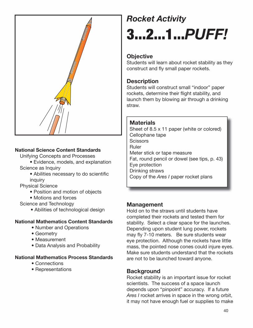
40
Rocket Activity 3...2...1...PUFF!ObjectiveStudents will learn about rocket stability as they construct and fl y small paper rockets.
DescriptionStudents will construct small “indoor” paper rockets, determine their fl ight stability, and launch them by blowing air through a drinking straw.
National Science Content StandardsUnifying Concepts and Processes • Evidence, models, and explanationScience as Inquiry • Abilities necessary to do scientifi c
inquiryPhysical Science • Position and motion of objects • Motions and forcesScience and Technology
• Abilities of technological design
National Mathematics Content Standards• Number and Operations• Geometry• Measurement• Data Analysis and Probability
National Mathematics Process Standards• Connections• Representations
MaterialsSheet of 8.5 x 11 paper (white or colored)Cellophane tapeScissorsRulerMeter stick or tape measureFat, round pencil or dowel (see tips, p. 43)Eye protectionDrinking strawsCopy of the Ares I paper rocket plans
ManagementHold on to the straws until students have completed their rockets and tested them for stability. Select a clear space for the launches. Depending upon student lung power, rockets may fl y 7-10 meters. Be sure students wear eye protection. Although the rockets have little mass, the pointed nose cones could injure eyes. Make sure students understand that the rockets are not to be launched toward anyone.
BackgroundRocket stability is an important issue for rocket scientists. The success of a space launch depends upon “pinpoint” accuracy. If a future Ares I rocket arrives in space in the wrong orbit, it may not have enough fuel or supplies to make

41
rendezvousing with the International Space Station possible. The crew would have to return to Earth and “chalk off” a failed mission. Stability means making sure the rocket follows a smooth path in flight. If it wobbles, the ride will be rough and extra fuel will be burned to get back on course. If it tumbles, it’s time to push the destruct button! An unstable rocket is dangerous. Fortunately, it is relatively easy to ensure stability if two things are kept in mind. These two things are center of mass and center of pressure. Center of mass (COM) is easy to demonstrate. It is the balance point of a rocket. Think of it like balancing a meter stick on an outstretched finger. If the stick rests horizontally, the COM is directly over your finger. If the COM is to the right of your finger, the stick will tip to the right. If to the left of your finger, the stick will tip to the left. An object, tossed into the air, rotates around its COM. Rockets also try to rotate around their COM while in flight. If this rotation is allowed to happen, the rocket becomes unstable. This is where Center of pressure (COP) comes to the rescue. COP is a balance point too but it has to do with the pressure exerted on the rocket surface by air molecules striking the surface as the rocket flies through the air. Like COM, there is a midpoint for the flight pressure on the rocket body. This is the COP. For a stable rocket, the COP is located to the rear of the rockets and the COM is to the front. To understand why the rocket is stable, let’s take a look at a couple of devices that also depend upon the placement of COM and COP. A weather vane pivots on a vertical axle when the wind blows. One end of the vane is pointed and the other end has a broad surface. When the wind blows, the broad end of the vane catches more air (more air pressure) and isblown down wind. The narrow end of the vane has less pressure exerted on it and points into the wind. One end of an arrow is long, narrow, and pointed while the other end has large feathers (or modern plastic fins). In flight, greater air
pressure is exerted on the feathers than on the narrow end. This keeps the arrow from tumbling around its COM and on course to its target. In both examples, there was more surface area on one side of the COM than the other. Both devices were stable. Stability of a rocket is the same thing. In this activity, students will build paper rockets and test them for stability using a drop test. Later activities will further explore the COM/COP concept and employ an advanced string test for rocket stability.Procedures: First Activity1. Demonstrate the construction technique
for making paper rockets. (Refer to the diagrams on the next page.) a. Cut a strip of paper for the rocket body
(about 4 cm wide by 28 cm long).
S NN
COM
COP
++
+
+
The positions of center of mass (red dot) and center of pressure (blue +) are shown for a weather vane, arrow and a rocket. The center of pressure is to the rear of the center of mass in each device. This enables them to point into the wind.
b. Use a round pencil as a form and roll the strip around the pencil.
c. Tape the long seam.d. Close off one end to make a nose cone. e. Cut out three our four fins. f. Tape the fins to the open (lower) end of the
rocket. Bend them outward to space them equally.
2. After students have constructed their rockets, show them how to perform drop tests to check for stability. Hold the rocket horizontally at eye level and drop it to the floor. If the nose of the rocket hits the floor first, the rocket is stable and ready for flight.

42
If the rocket falls horizontally or the fi n end hits fi rst, the rocket is unstable. Larger fi ns may be needed to stabilize the rocket. Have students perform their own stability tests and make adjustments to their rockets if needed.
3. Finally, demonstrate the launch procedure for the rocket. Stand at one end of your launch range. Insert a straw into the rocket body. Aim the rocket down range and puff strongly into the straw. Liftoff!
4. Talk over ideas for safety. Discuss wearing safety glasses. Ask students what should be done when they retrieve their rockets for another launch. (Other students should wait until the range is clear before launching.)
5. Have students improve their rocket design by holding distance trials. Students will launch their rocket three times and fi nd the average distance the rocket travels. They will then try to improve their rocket design to get greater distance. The student data sheets outline the procedures and provide space to jot down and analyze data.
Making and Attaching Fins
Cut tabs and spread. Tape tabs to rocket tube.
Fold paper square. Cut out fi ns. Spread fi ns and tape to rocket tube. Bend fi n tips outward.
Cut crownpoints and tape
Gather end and tape
Fold endover andtape
Making Nose Cones
Tape and trim ends.
ARES To The Moon and Mars
ARES To The Moon and Mars
ARES To The Moon and Mars
Rolling Rocket Tubes
Use 4X28 cm strips of paper
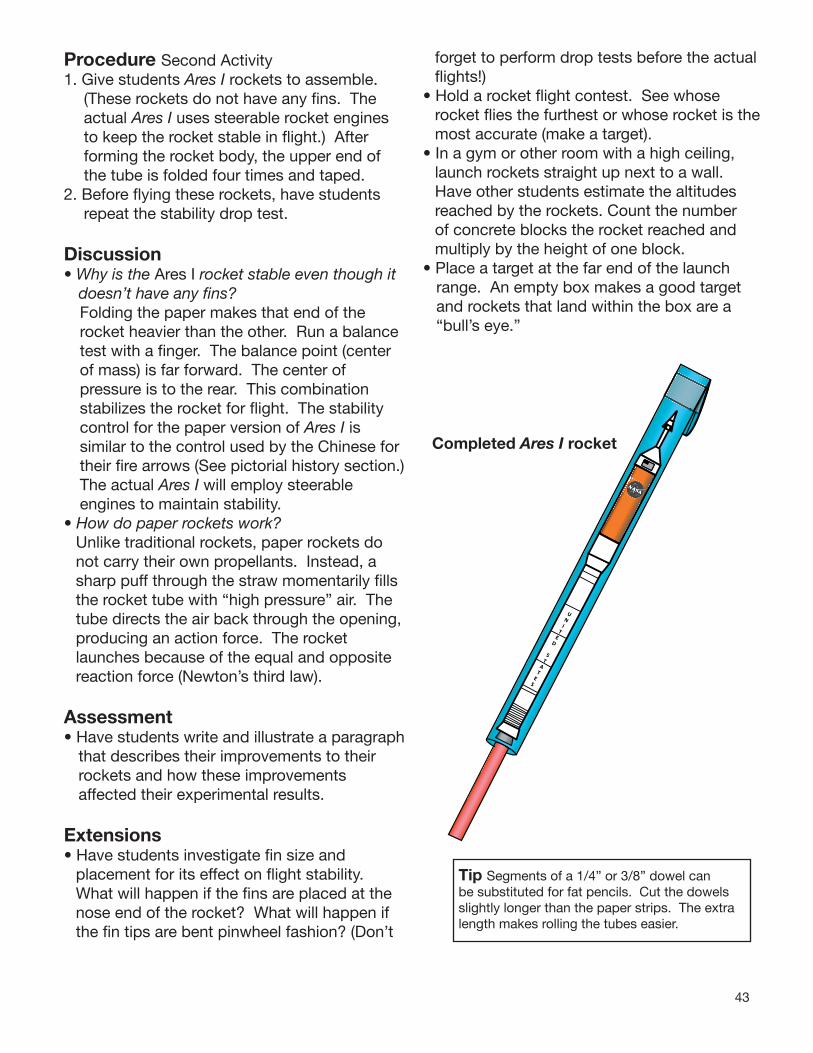
43
Procedure Second Activity 1. Give students Ares I rockets to assemble.
(These rockets do not have any fi ns. The actual Ares I uses steerable rocket engines to keep the rocket stable in fl ight.) After forming the rocket body, the upper end of the tube is folded four times and taped.
2. Before fl ying these rockets, have students repeat the stability drop test.
Discussion• Why is the Ares I rocket stable even though it
doesn’t have any fi ns?Folding the paper makes that end of the rocket heavier than the other. Run a balance test with a fi nger. The balance point (center of mass) is far forward. The center of pressure is to the rear. This combination stabilizes the rocket for fl ight. The stability control for the paper version of Ares I is similar to the control used by the Chinese for their fi re arrows (See pictorial history section.) The actual Ares I will employ steerable engines to maintain stability.
• How do paper rockets work?Unlike traditional rockets, paper rockets do not carry their own propellants. Instead, a sharp puff through the straw momentarily fi lls the rocket tube with “high pressure” air. The tube directs the air back through the opening, producing an action force. The rocket launches because of the equal and opposite reaction force (Newton’s third law).
Assessment• Have students write and illustrate a paragraph
that describes their improvements to their rockets and how these improvements affected their experimental results.
Extensions• Have students investigate fi n size and
placement for its effect on fl ight stability. What will happen if the fi ns are placed at the nose end of the rocket? What will happen if the fi n tips are bent pinwheel fashion? (Don’t
forget to perform drop tests before the actual fl ights!)
• Hold a rocket fl ight contest. See whose rocket fl ies the furthest or whose rocket is themost accurate (make a target).
• In a gym or other room with a high ceiling, launch rockets straight up next to a wall. Have other students estimate the altitudes reached by the rockets. Count the number of concrete blocks the rocket reached and multiply by the height of one block.
• Place a target at the far end of the launch range. An empty box makes a good target and rockets that land within the box are a “bull’s eye.”
Completed Ares I rocket
Tip Segments of a 1/4” or 3/8” dowel can be substituted for fat pencils. Cut the dowels slightly longer than the paper strips. The extra length makes rolling the tubes easier.
UN
IT
ED
ST
AT
ES
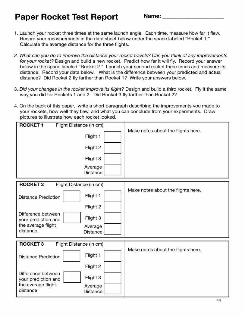
44
Paper Rocket Test Report Name: ______________________
1. Launch your rocket three times at the same launch angle. Each time, measure how far it flew. Record your measurements in the data sheet below under the space labeled “Rocket 1.” Calculate the average distance for the three flights.
2. What can you do to improve the distance your rocket travels? Can you think of any improvements for your rocket? Design and build a new rocket. Predict how far it will fly. Record your answer below in the space labeled “Rocket 2.” Launch your second rocket three times and measure its distance. Record your data below. What is the difference between your predicted and actual distance? Did Rocket 2 fly farther than Rocket 1? Write your answers below.
3. Did your changes in the rocket improve its flight? Design and build a third rocket. Fly it the same way you did for Rockets 1 and 2. Did Rocket 3 fly farther than Rocket 2?
4. On the back of this paper, write a short paragraph describing the improvements you made to your rockets, how well they flew, and what you can conclude from your experiments. Draw pictures to illustrate how each rocket looked.
ROCKET 1 Flight Distance (in cm)
Flight 1
Flight 2
Flight 3
Average Distance
ROCKET 2 Flight Distance (in cm)
Flight 1
Flight 2
Flight 3
Average Distance
Distance Prediction
Difference between your prediction and the average flight distance
ROCKET 3 Flight Distance (in cm)
Flight 1
Flight 2
Flight 3
Average Distance
Distance Prediction
Difference between your prediction and the average flight distance
Make notes about the flights here.
e notes about the flights here.
e notes about the flights here.akM
akM

45
UNITED
STATES
UNITED
STATES
UNITED
STATES
UNITED
STATES
Are
s I P
aper
Ro
cket
Pat
tern
sFold 1
Fold 2
Fold 3
Fold 4
Fold 1
Fold 2
Fold 3
Fold 4
Fold 1
Fold 2
Fold 3
Fold 4
Fold 1
Fold 2
Fold 3
Fold 4
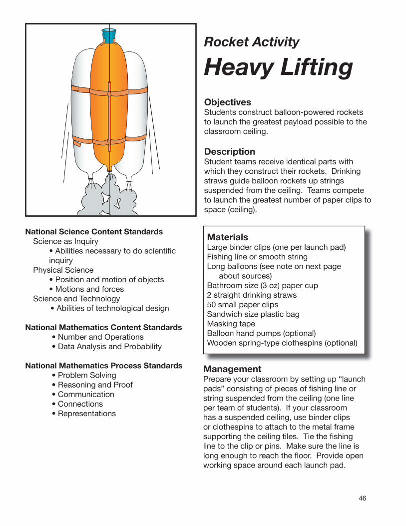
46
Rocket Activity Heavy Lifting
ObjectivesStudents construct balloon-powered rockets to launch the greatest payload possible to the classroom ceiling.
DescriptionStudent teams receive identical parts with which they construct their rockets. Drinking straws guide balloon rockets up strings suspended from the ceiling. Teams compete to launch the greatest number of paper clips to space (ceiling).
National Science Content StandardsScience as Inquiry • Abilities necessary to do scientifi c
inquiryPhysical Science • Position and motion of objects • Motions and forcesScience and Technology
• Abilities of technological design
National Mathematics Content Standards• Number and Operations• Data Analysis and Probability
National Mathematics Process Standards• Problem Solving• Reasoning and Proof• Communication• Connections• Representations
MaterialsLarge binder clips (one per launch pad)Fishing line or smooth stringLong balloons (see note on next page
about sources)Bathroom size (3 oz) paper cup2 straight drinking straws50 small paper clipsSandwich size plastic bagMasking tapeBalloon hand pumps (optional)Wooden spring-type clothespins (optional)
ManagementPrepare your classroom by setting up “launch pads” consisting of pieces of fi shing line or string suspended from the ceiling (one line per team of students). If your classroom has a suspended ceiling, use binder clips or clothespins to attach to the metal frame supporting the ceiling tiles. Tie the fi shing line to the clip or pins. Make sure the line is long enough to reach the fl oor. Provide open working space around each launch pad.
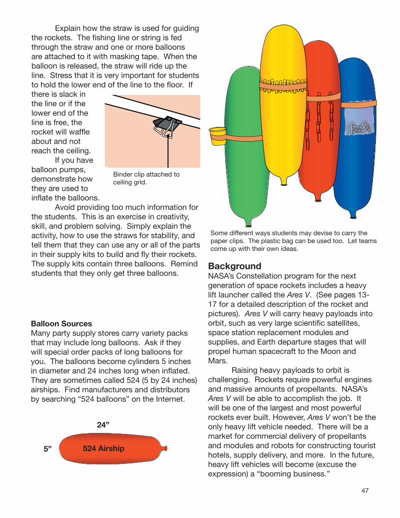
47
Explain how the straw is used for guiding the rockets. The fi shing line or string is fed through the straw and one or more balloons are attached to it with masking tape. When the balloon is released, the straw will ride up the line. Stress that it is very important for students to hold the lower end of the line to the fl oor. If there is slack in the line or if the lower end of the line is free, the rocket will waffl e about and not reach the ceiling. If you have balloon pumps, demonstrate how they are used to infl ate the balloons. Avoid providing too much information for the students. This is an exercise in creativity, skill, and problem solving. Simply explain the activity, how to use the straws for stability, and tell them that they can use any or all of the partsin their supply kits to build and fl y their rockets. The supply kits contain three balloons. Remind students that they only get three balloons.
Binder clip attached to ceiling grid.
Balloon Sources Many party supply stores carry variety packs that may include long balloons. Ask if they will special order packs of long balloons for you. The balloons become cylinders 5 inches in diameter and 24 inches long when infl ated. They are sometimes called 524 (5 by 24 inches) airships. Find manufacturers and distributors by searching “524 balloons” on the Internet.
24”
5” 524 Airship
Some different ways students may devise to carry the paper clips. The plastic bag can be used too. Let teams come up with their own ideas.
BackgroundNASA’s Constellation program for the next generation of space rockets includes a heavy lift launcher called the Ares V. (See pages 13-17 for a detailed description of the rocket and pictures). Ares V will carry heavy payloads into orbit, such as very large scientifi c satellites, space station replacement modules and supplies, and Earth departure stages that will propel human spacecraft to the Moon and Mars. Raising heavy payloads to orbit is challenging. Rockets require powerful engines and massive amounts of propellants. NASA’s Ares V will be able to accomplish the job. It will be one of the largest and most powerful rockets ever built. However, Ares V won’t be the only heavy lift vehicle needed. There will be a market for commercial delivery of propellants and modules and robots for constructing tourist hotels, supply delivery, and more. In the future, heavy lift vehicles will become (excuse the expression) a “booming business.”

48
Procedure1. Divide your students into teams of three.
Explain the project to them.
“NASA is looking for creative ideas for launching heavy payloads into orbit. Payloads include parts and supplies for the International Space Station and spacecraft that will carry humans to the Moon and Mars. NASA is also interested in rockets that can transport large fuel tanks that will be used to power deep space rockets. You are challenged to build the most effi cient heavy-lift rocket from the same set of materials. The team that is able to lift the greatest payload into space (the ceiling) is the winner.”
2. Provide each team with an identical kit of materials. Tell them that any or all of these materials can be used for their rockets.
3. Review the launching procedure. Explain how the straw guides the rocket up the fi shing line or string and that the line must be held snug to the fl oor for the launch. Remind the teams that they only get three balloons. They can launch as many times as they want to but should try to improve how many paper clips they can successfully lift.
4. Draw a chart on the board for teams to record their results (i.e., the number of paper clips that reach the ceiling).
Tip If you wish to do so, provide one extra balloon to each team as a replacement in case of a mishap (pop!) or as a fourth rocket for their cluster. Make a small coupon for the extra balloon and put it in the parts bag. The coupons will help you keep track of which teams have already requested an extra balloon.
Discussion• Why is NASA supportive of commercial space
companies? NASA’s space efforts are aimed at
expanding our horizons in space. Although their space rockets are easily capable of launching communications, weather, and Earth resources satellites, NASA continually looks beyond. NASA explores, and when it pioneers a new technology, it seeks to turn over continued development to U.S. commercial interests. That way, NASA can focus on and advance to the next new horizon. NASA’s current new horizons include the fi rst permanent bases on the Moon and the fi rst human expeditions to Mars. These are demanding challenges. When they are met, commercial space companies will follow, permitting NASA to move on to even greater challenges.
• Why is it important to construct effi cient heavy-lift vehicles?
Traveling into space is a very diffi cult and expensive endeavor. Huge rockets and tremendous amounts of propellants are required to accomplish the job. With some rockets, launch costs were approximately $20,000 per kilogram of payload delivered into Earth orbit. If that cost were to continue, imagine staying at a space hotel where it would cost about $10,000 for a half liter bottle of drinking water! Improving heavy-lift rockets (lighter rocket structures, more propellant effi cient engines, etc.) will enable us to accomplish much more in space at far more reasonable costs!
Tip Occasionally, a balloon will have a tiny pinhole that will prevent it from being infl ated or from holding air very long. Keep a small supply of replacement balloons.
49
Assessment• Have each team describe their design to the
class. How many balloons did they use?How many paperclips did their rocket carry
to the ceiling?How did they attach the paperclips to the
balloon?What problems did they encounter? How
did they solve those problems?
• Write a summary of your launch vehicle using correct science and technology terms (e.g., lift, payload, mass, thrust).
Extensions• Challenge students to design a two-stage
rocket. The lower balloon “fires” before the upper balloon. The upper balloon carries the payload to the ceiling.

50
Heavy Lift Rocket Mission Report
Team MemberNames:
FlightTest
Actual Mass Lifted
Predict How MuchMass Your Rocket
Will Lift1 paper clip = 2gm
1.
2.
3.
4.
5.
Make a sketch of your best rocket
Describe your firstrocket.
How did you change your rocket to make it carry more mass?
What other ways could you change your rocket to improve it?
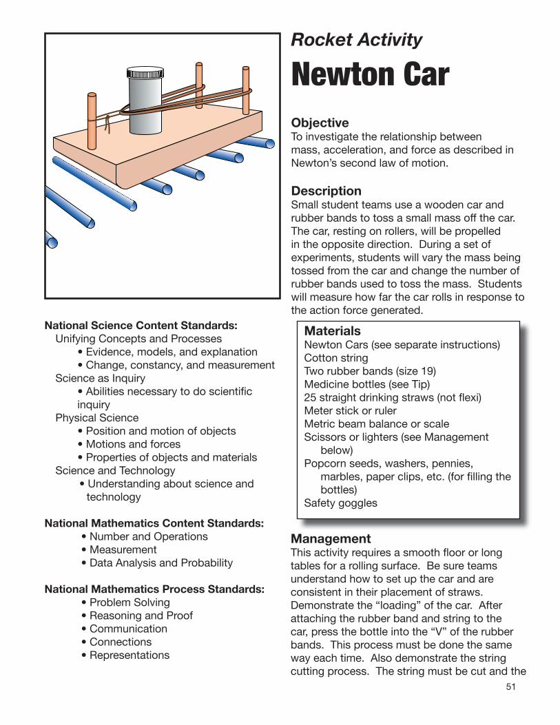
51
Rocket Activity
Newton Car
ObjectiveTo investigate the relationship between mass, acceleration, and force as described in Newton’s second law of motion.
DescriptionSmall student teams use a wooden car and rubber bands to toss a small mass off the car. The car, resting on rollers, will be propelled in the opposite direction. During a set of experiments, students will vary the mass being tossed from the car and change the number of rubber bands used to toss the mass. Students will measure how far the car rolls in response to the action force generated.
National Science Content Standards:Unifying Concepts and Processes • Evidence, models, and explanation • Change, constancy, and measurementScience as Inquiry • Abilities necessary to do scientifi c
inquiryPhysical Science • Position and motion of objects • Motions and forces • Properties of objects and materialsScience and Technology
• Understanding about science and technology
National Mathematics Content Standards:• Number and Operations• Measurement• Data Analysis and Probability
National Mathematics Process Standards:• Problem Solving• Reasoning and Proof• Communication• Connections• Representations
Management
MaterialsNewton Cars (see separate instructions)Cotton stringTwo rubber bands (size 19)Medicine bottles (see Tip)25 straight drinking straws (not fl exi)Meter stick or rulerMetric beam balance or scaleScissors or lighters (see Management
below)Popcorn seeds, washers, pennies,
marbles, paper clips, etc. (for fi lling the bottles)
Safety goggles
ManagementThis activity requires a smooth fl oor or long tables for a rolling surface. Be sure teams understand how to set up the car and are consistent in their placement of straws. Demonstrate the “loading” of the car. After attaching the rubber band and string to the car, press the bottle into the “V” of the rubber bands. This process must be done the same way each time. Also demonstrate the string cutting process. The string must be cut and the

52
scissors moved out of the way in one smooth and quick movement. Lighters can also be used for burning through the string. Have students light the ends of the string dangling down from the knot. The fl ame will climb up the strings and burn through the knot. Students must wear eye protection with either string cutting technique.
Slide rubber band ends over twin posts
Slip rubber band through string loop
Stretch string over third post
Loading the Newton Car
BackgroundAlthough the purpose of the Newton Car is to investigate Newton’s second law of motion, it provides an excellent demonstration of all three laws. The car is a slingshot-like device. Rubber bands are stretched between two posts and held with a string loop ringing a third post. A bottle, holding various materials that can be changed to vary its mass, is placed between the stretched rubber bands. When the string is cut, the bottle is tossed off the car and the car travels the other way on straw rollers. Newton’s fi rst law is demonstrated by the act of exerting a force. The car remains at rest until the mass is expelled, producing a force. The car then moves. The action force exerted on the car produces an equal and opposite reaction force. The car moves the other way from the tossed bottle. This demonstrates Newton’s third law.
How far the car moves demonstrates the second law. The magnitude of the force is determined by how much mass is tossed and how fast it is accelerated off the car. By varying the mass and the number of rubber bands, students are able to see a visual demonstration of the relationship of mass and acceleration on force. The greater the mass of the bottle and its contents and the greater the acceleration (more rubber bands), the greater the force. The effect is that the car will travel further in the opposite direction. (Refer to pages 19-23 for a more detailed explanation of Newton’s laws of motion.)
Procedure Making Newton Cars
Materials 1 1 X 3 X 8 inch board*3 1/4” diameter by 2 1/2” long dowels (or wood screws)Wood glue
1” 1 1/4”
1”
3/16”
2 1/2”
NewtonCarTop View
Bevel lower edge
8”
1. Cut the board into 12 8” lengths. (Optional: Bevel one edge as shown on the previous page.)
2. Drill three 1/4” holes 3/8” deep for the dowels. If using screws for posts instead of dowels, skip Step 3.
3. Glue the dowels into the holes. If desired, bevel the upper end of the dowels with sand paper.
* Note: Dimensions of lumber are based on rough cuts. When planed, thickness and width are smaller. A 1X3” board is actually 0.75 by 2.5 inches.

53
Procedure The Experiment1. Provide student teams with the instruction
sheet on how to set up the Newton Car and the data sheet.
2. Clear areas for each team to set up their experiment.
3. Provide a station where teams can fill their bottles with different materials to change their total mass. Place the popcorn seeds, washers, etc., in different bowls for easy access. The bottles do not have to be filled to the top. However, the rubber bands should be positioned around the approximatecenter of mass of the bottle to get a uniform toss.
4. Check each team to ensure they are being consistent in their procedures. For instance, placing straws differently for each test would introduce a new variable into the experiment that could affect the results.
Tip: Provide masking tape so that students can use small tape pieces to mark the positions of the straws for consistency.
Discussion• How does adding additional rubber bands
change the acceleration?
Like all matter, the bottle has inertia, which is the property of resistance to change in motion. Newton’s first law of motion is often referred to as the law of inertia. A force is needed to change the motion of the bottle. In this experiment the inertia of the bottle retards the contraction of the rubber band. Two rubber bands, working together, are able to contract more rapidly and consequently are able to impart a greater acceleration to the bottle.
Tip: Ask a pharmacist for a donation of new, 8-dram-size medicine bottles.
Assessment• Review the experiment report for
completeness and check team statements, explaining the relationship between mass, acceleration, and the distances the Newton Cars traveled.
• Ask students for other examples of Newton’s laws of motion at work.
Extensions• Newton’s second law of motion can also be
demonstrated using a water rocket. Vary the pressure in the water rocket by using different numbers of pumps. Vary the amount of water inside the bottle. Changes in mass and acceleration will affect the performance of the rocket in flight.
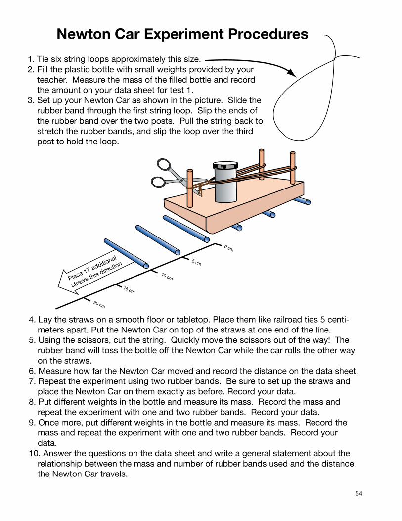
54
Newton Car Experiment Procedures
1. Tie six string loops approximately this size.2. Fill the plastic bottle with small weights provided by your
teacher. Measure the mass of the filled bottle and record the amount on your data sheet for test 1.
3. Set up your Newton Car as shown in the picture. Slide the rubber band through the first string loop. Slip the ends of the rubber band over the two posts. Pull the string back to stretch the rubber bands, and slip the loop over the third post to hold the loop.
Place 17 additional
straws this direction
0 cm
5 cm
10 cm
15 cm
20 cm
4. Lay the straws on a smooth floor or tabletop. Place them like railroad ties 5 centi-meters apart. Put the Newton Car on top of the straws at one end of the line.
5. Using the scissors, cut the string. Quickly move the scissors out of the way! The rubber band will toss the bottle off the Newton Car while the car rolls the other way on the straws.
6. Measure how far the Newton Car moved and record the distance on the data sheet.7. Repeat the experiment using two rubber bands. Be sure to set up the straws and
place the Newton Car on them exactly as before. Record your data.8. Put different weights in the bottle and measure its mass. Record the mass and
repeat the experiment with one and two rubber bands. Record your data.9. Once more, put different weights in the bottle and measure its mass. Record the
mass and repeat the experiment with one and two rubber bands. Record your data.
10. Answer the questions on the data sheet and write a general statement about the relationship between the mass and number of rubber bands used and the distance the Newton Car travels.

55
Newton Car Experiment ReportTeam Members:
Distance Car Traveled
Mass of Bottle
Number of RubberBands
Test 1
1
2
Test 2
1
2
Test 3
1
2
Did the number of rubber bands affect how far the Newton Car moved? Describe what happened.
Did the mass of the bottle affect how far the Newton Car moved? Describe what happened.
Construct a bar graph showing how far the Newton Car moved for each test.
0 10 20 30 40 50 60 70 80 90 100 110 120 130 140 150 160 170 180 190 200Centimeters Traveled
Test 1 (1)
(2)
Test 2 (1)
(2)
Test 3 (1)
(2)
On the back of this page write a short statement explaining the relationship between the amount of mass in the bottle, the number of rubber bands used, and the distance the Newton Car traveled.
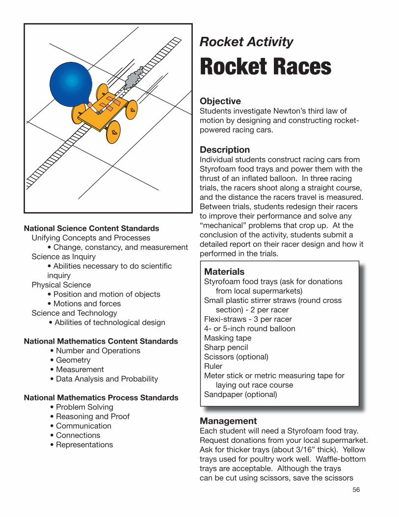
56
Rocket Activity
Rocket Races ObjectiveStudents investigate Newton’s third law of motion by designing and constructing rocket-powered racing cars.
DescriptionIndividual students construct racing cars from Styrofoam food trays and power them with the thrust of an infl ated balloon. In three racing trials, the racers shoot along a straight course, and the distance the racers travel is measured. Between trials, students redesign their racers to improve their performance and solve any “mechanical” problems that crop up. At the conclusion of the activity, students submit a detailed report on their racer design and how it performed in the trials.
MaterialsStyrofoam food trays (ask for donations
from local supermarkets)Small plastic stirrer straws (round cross
section) - 2 per racerFlexi-straws - 3 per racer4- or 5-inch round balloonMasking tapeSharp pencilScissors (optional)RulerMeter stick or metric measuring tape for
laying out race courseSandpaper (optional)
National Science Content StandardsUnifying Concepts and Processes • Change, constancy, and measurementScience as Inquiry • Abilities necessary to do scientifi c
inquiryPhysical Science • Position and motion of objects • Motions and forcesScience and Technology
• Abilities of technological design
National Mathematics Content Standards• Number and Operations• Geometry• Measurement• Data Analysis and Probability
National Mathematics Process Standards• Problem Solving• Reasoning and Proof• Communication• Connections• Representations
ManagementEach student will need a Styrofoam food tray. Request donations from your local supermarket. Ask for thicker trays (about 3/16” thick). Yellow trays used for poultry work well. Waffl e-bottom trays are acceptable. Although the trays can be cut using scissors, save the scissors

57
for trimming. It is much easier to score the Styrofoam with a sharp pencil and then break away the pieces. Score lines can be continuous or the tip of the pencil can be punched into the Styrofoam to make a dotted line. Demonstrate the scoring process to your students. After the pieces are broken out, the edges are smoothed. Wheels can be smoothed by rolling them on a hard surface while applying pressure. Sandpaper can also be used for smoothing. Lay out a race course in a large open space or hallway. The space can be carpeted, but textured carpets interfere with the movements of the racers. Stretch out a 10 meter-long line of masking tape and mark 10-centimeter intervals. If you have a 10 meter tape measure, just tape it to the floor. Double check the taping of the balloon to the straw. The balloon should be completely sealed, or it will be difficult to inflate, and some of its thrust will be lost through the leaks. Pre- inflating the balloon will loosen it and make it easier to inflate through the straw. Guide students through the redesign process to improve their racers. If their racers are not running well, ask them what they think the problem is. Then, ask them what they can do about it. Typical problems include having wheels too tight to the sides of the cars (friction), wheels or axles mounted crooked (racer curves off course), and axles not mounted in center of wheel or wheels not round (like “clown car” wheels).
BackgroundThe rocket racer is an excellent demonstration of Newton’s third law of motion. Air is compressed inside a balloon that is expanded. When the nossle is released, the balloon returns to its original uninflated size by propelling the air out its nozzle. The straw mounted to the balloon extends the nozzle beyond the rear end of the car. The action force of the expelling air produces a reaction force that pushes the racer in the opposite direction. The racer’s wheels reduce friction with the floor, and the racer takes off down the race course.
Although the rocket racer seems simple, there are many challenging complexities in its operation. In principle (Newton’s second law of motion), the less mass the car has, the greater its acceleration will be. Generally, heavy rocket racers do less well than lighter racers. However, very small racers are limited by other factors. Vehicles with short wheel bases tend to circle or partially lift off the floor. Balance becomes a problem. The mass of the balloon may cause the car to tilt nose down to the floor, causing a poor start. The engineering design of the racer is very important. Many designs are possible, including wide, narrow, and I-beam shaped bodies and three, four, or even six wheels.
Demonstrate the action-reaction principle by inserting a pin through the straw and into a pencil eraser. Inflate the balloon, and it will pinwheel around the pencil as air rushes out. Compare this to the straight thrust produced by the balloon in the rocket cars.
Students will have to review the trade-offs of their design. For example, an extra-long body may provide a straighter path, but the car might travel a shorter distance as a result.
Procedure1. Explain the activity to the students. Provide
them with the How To Build A Rocket Racer Sheet. Go over the construction steps and demonstrate how to snap out parts, mount the wheels, and attach the straw to the balloon.

58
2. Stress that the racer shown in the instructions is a basic racer. Many designs are possible. Have them think up their own designs.
3. Review the Rocket Racer Data Sheet and make sure students know how to fill out the graphs and what data they should collect.
4. Distribute materials and lay out the racer course.
5. When student racers are ready, have one or two students at a time inflate their balloons and pinch off the end of the straw to keep the air inside. Have them place their racers just behind the starting line and release the straws. Regardless of how much curving a racer does, the measured distance is how far along the straight line of the race course the car reached.
6. Post distance records to motivate students to modify their racers to set new records.
7. After each racer runs three times, have students complete their data sheets and sketch their final design on the design sheets.
Discussion• Would it be a good idea for automobiles to be
powered by rocket engines? If there was only one rocket powered
automobile on the road, it would work fine. However, imagine rush hour traffic loaded with rocket cars. Each would blow exhaust gas at the vehicles to the rear.
• How are the wheels on a rocket racer similar to and different from wheels on a regular automobile?
Rocket racer wheels reduce friction with the ground. They turn when the air coming from the balloon exerts a thrust. Wheels for an automobile also permit the car to roll across the ground, but the thrust of an automobile depends upon friction. The engine turns the wheels, and friction with the rubber and the pavement transmits the action force so that the car rolls forward.
Assessment• Review student Rocket Racer Data Sheets
and Design Sheets. • Have students write an explanation of
Newton’s third law of motion using their rocket racers as examples.
Extensions• Hold Rocket Racer drag races. Lay out a
3-meter-long course. The fastest car is the one that crosses the finish line first. Calculate racer average speed by timing start to finish with a stopwatch (e.g., four seconds to go three meters = 0.75 m/second or 2.7 km/h).
• Have students try multiple balloons for additional thrust. How will students design cars that are balanced with the extra load?
• Have students control the thrust of their balloons by inflating them to the same diameter each time. How can students ensure that the balloon is always the same?
• Using the same materials, what other devices can be created that demonstrate the action-reaction principle of Newton’s third law of motion?
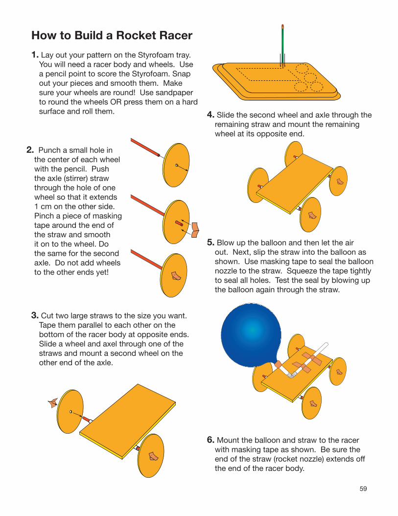
59
How to Build a Rocket Racer
1. Lay out your pattern on the Styrofoam tray. You will need a racer body and wheels. Use a pencil point to score the Styrofoam. Snap out your pieces and smooth them. Make sure your wheels are round! Use sandpaper to round the wheels OR press them on a hard surface and roll them.
2. Punch a small hole in the center of each wheel with the pencil. Push the axle (stirrer) straw through the hole of one wheel so that it extends 1 cm on the other side. Pinch a piece of maskingtape around the end of the straw and smooth it on to the wheel. Do the same for the second axle. Do not add wheels to the other ends yet!
3. Cut two large straws to the size you want. Tape them parallel to each other on the bottom of the racer body at opposite ends. Slide a wheel and axel through one of the straws and mount a second wheel on the other end of the axle.
4. Slide the second wheel and axle through the remaining straw and mount the remaining wheel at its opposite end.
5. Blow up the balloon and then let the air out. Next, slip the straw into the balloon as shown. Use masking tape to seal the balloon nozzle to the straw. Squeeze the tape tightly to seal all holes. Test the seal by blowing up the balloon again through the straw.
6. Mount the balloon and straw to the racer with masking tape as shown. Be sure the end of the straw (rocket nozzle) extends off the end of the racer body.

60
Wheel PatternsCut out the desired wheel size. Trace the wheel outline on the Styrofoam. Punch the pencil point through the cross to mark the center.

61
TO
P V
IEW
FRO
NT
VIE
WS
IDE
VIE
W
om
the
Roc
ket
Rac
er
Des
ign
Sh
eet
Dra
w a
dia
gra
m s
how
ing
yo
ur b
est
des
ign
ock
et r
acer
.
e o
n th
e g
rap
hs =
1cm
.
Nam
e: _
____
____
____
____
_
for
a r
Sho
w y
our
rac
er a
s se
en f
rfr
ont
, to
p, a
nd s
ide.
Eac
h sq
uar

62
Roc
ket
Rac
er D
ata
Sh
eet
___
____
____
____
___
Nam
e:
Roc
ket
Rac
er
Tria
l #1
0
100
200
30
0
4
00
500
600
70
0
8
00
9
00
1
,000
cm
Des
crib
e ho
w y
our
rock
et r
acer
ran
(str
aigh
t, c
urve
d, c
ircle
s, s
tuck
, etc
.).
Did
you
r ra
cer
per
form
as
wel
l as
you
hop
ed?
Exp
lain
why
or
why
not
.
Roc
ket
Rac
er
Tria
l #2
0
100
200
30
0
4
00
500
600
70
0
8
00
9
00
1,00
0 cm
How
did
you
imp
rove
you
r ro
cket
rac
er?
Pre
dic
t ho
w fa
r yo
ur r
acer
will
run
. ___
____
____
_ cm
Des
crib
e ho
w y
our
rock
et r
acer
ran
.
Did
you
r im
pro
vem
ents
wor
k? E
xpla
in w
hy o
r w
hy n
ot.
Roc
ket
Rac
er
Tria
l #3
0
100
200
30
0
4
00
500
600
70
0
8
00
9
00
1
,000
cm
How
did
you
imp
rove
you
r ro
cket
rac
er?
Pre
dic
t ho
w fa
r yo
ur r
acer
will
run
. ___
____
____
_ cm
Des
crib
e ho
w y
our
rock
et r
acer
ran
.
Did
you
r im
pro
vem
ents
wor
k? E
xpla
in w
hy o
r w
hy n
ot.
Sha
de
in t
he g
rap
h sh
owin
g ho
w fa
r yo
ur r
ocke
t ra
cer
trav
eled
in c
entim
eter
s.
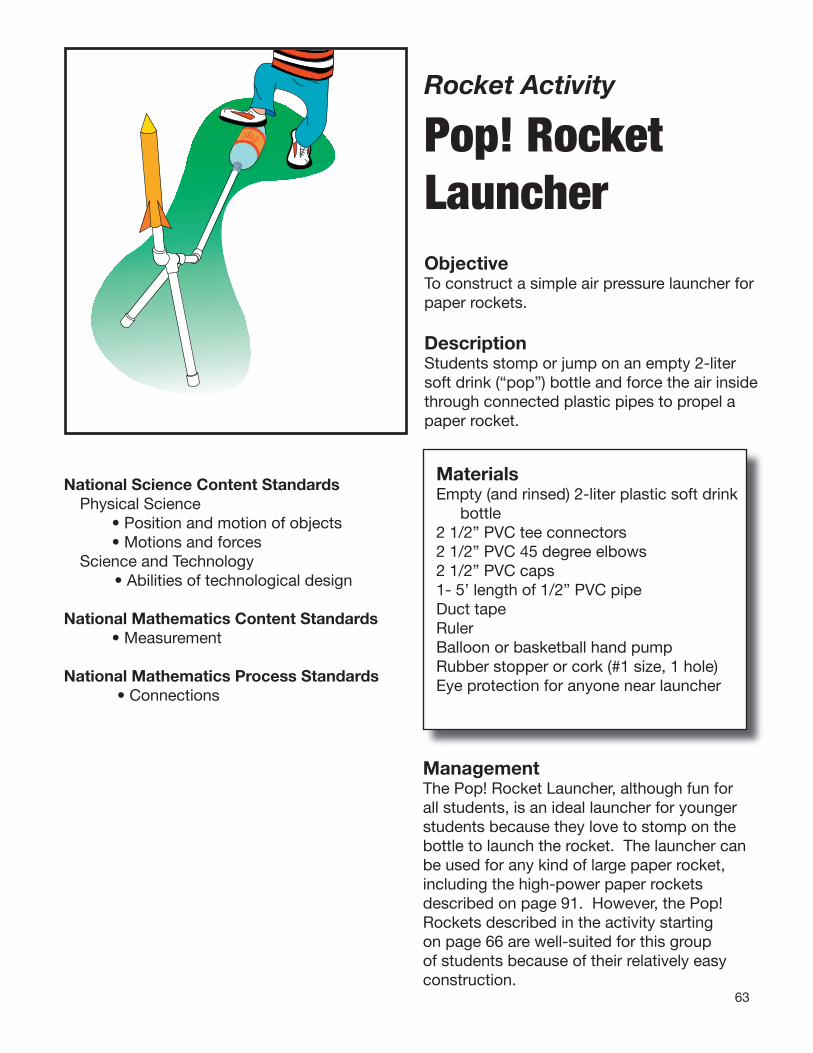
63
Rocket Activity
Pop! Rocket Launcher ObjectiveTo construct a simple air pressure launcher for paper rockets.
DescriptionStudents stomp or jump on an empty 2-liter soft drink (“pop”) bottle and force the air inside through connected plastic pipes to propel a paper rocket.
MaterialsEmpty (and rinsed) 2-liter plastic soft drink
bottle2 1/2” PVC tee connectors2 1/2” PVC 45 degree elbows2 1/2” PVC caps1- 5’ length of 1/2” PVC pipe Duct tapeRulerBalloon or basketball hand pumpRubber stopper or cork (#1 size, 1 hole)Eye protection for anyone near launcher
Pop!
National Science Content StandardsPhysical Science • Position and motion of objects • Motions and forcesScience and Technology
• Abilities of technological design
National Mathematics Content Standards • Measurement
National Mathematics Process Standards• Connections
ManagementThe Pop! Rocket Launcher, although fun for all students, is an ideal launcher for younger students because they love to stomp on the bottle to launch the rocket. The launcher can be used for any kind of large paper rocket, including the high-power paper rockets described on page 91. However, the Pop! Rockets described in the activity starting on page 66 are well-suited for this group of students because of their relatively easy construction.
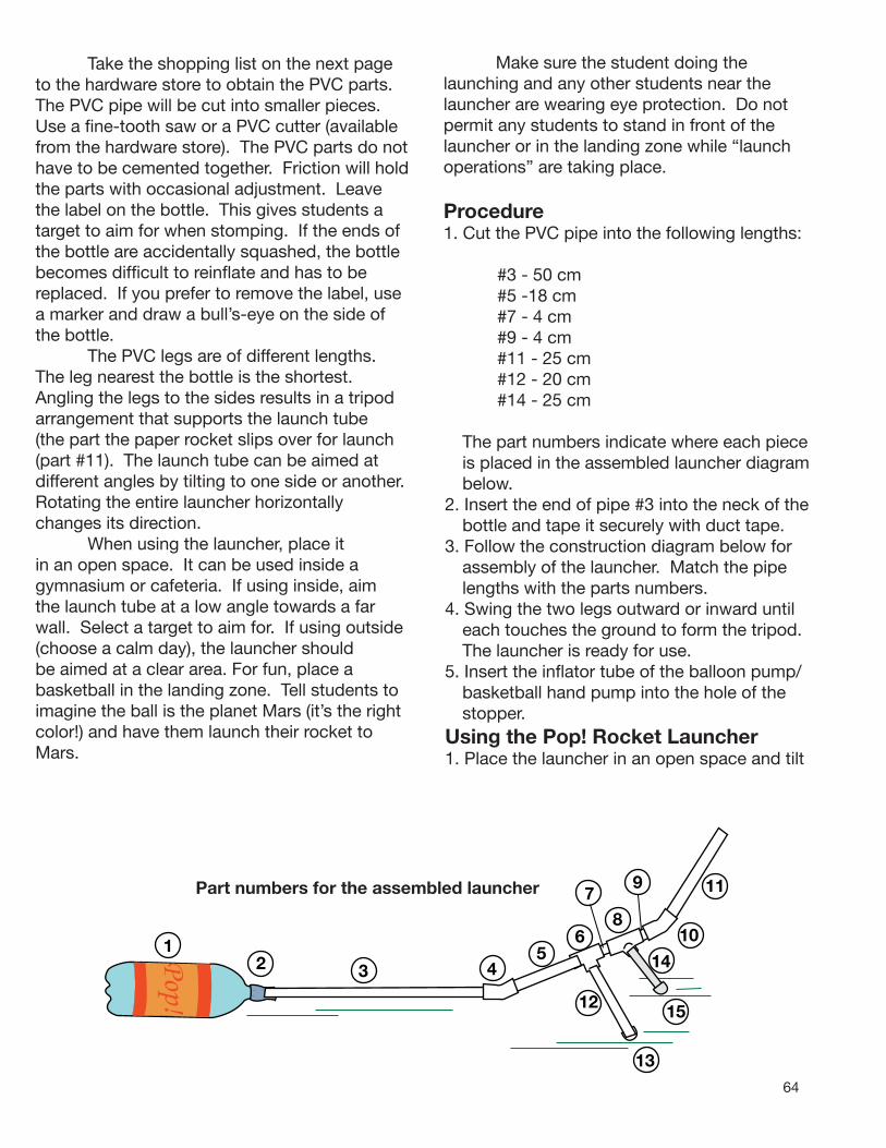
64
12Pop!
3
10
1456
12 15
4
Take the shopping list on the next page to the hardware store to obtain the PVC parts. The PVC pipe will be cut into smaller pieces. Use a fine-tooth saw or a PVC cutter (available from the hardware store). The PVC parts do nothave to be cemented together. Friction will holdthe parts with occasional adjustment. Leave the label on the bottle. This gives students a target to aim for when stomping. If the ends of the bottle are accidentally squashed, the bottle becomes difficult to reinflate and has to be replaced. If you prefer to remove the label, use a marker and draw a bull’s-eye on the side of the bottle. The PVC legs are of different lengths. The leg nearest the bottle is the shortest. Angling the legs to the sides results in a tripod arrangement that supports the launch tube (the part the paper rocket slips over for launch (part #11). The launch tube can be aimed at different angles by tilting to one side or another. Rotating the entire launcher horizontally changes its direction. When using the launcher, place it in an open space. It can be used inside a gymnasium or cafeteria. If using inside, aim the launch tube at a low angle towards a far wall. Select a target to aim for. If using outside (choose a calm day), the launcher should be aimed at a clear area. For fun, place a basketball in the landing zone. Tell students to imagine the ball is the planet Mars (it’s the right color!) and have them launch their rocket to Mars.
Make sure the student doing the launching and any other students near the launcher are wearing eye protection. Do not permit any students to stand in front of the launcher or in the landing zone while “launch operations” are taking place.
Part numbers for the assembled launcher
13
9 11
87
Procedure1. Cut the PVC pipe into the following lengths:
#3 - 50 cm#5 -18 cm#7 - 4 cm#9 - 4 cm#11 - 25 cm#12 - 20 cm#14 - 25 cm
The part numbers indicate where each piece is placed in the assembled launcher diagram below.
2. Insert the end of pipe #3 into the neck of the bottle and tape it securely with duct tape.
3. Follow the construction diagram below for assembly of the launcher. Match the pipe lengths with the parts numbers.
4. Swing the two legs outward or inward until each touches the ground to form the tripod. The launcher is ready for use.
5. Insert the inflator tube of the balloon pump/basketball hand pump into the hole of the stopper.
Using the Pop! Rocket Launcher1. Place the launcher in an open space and tilt
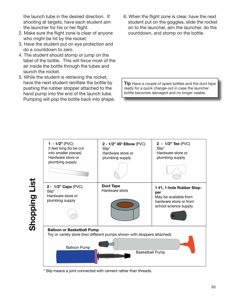
65
the launch tube in the desired direction. If shooting at targets, have each student aim the launcher for his or her fl ight.
2. Make sure the fl ight zone is clear of anyone who might be hit by the rocket.
3. Have the student put on eye protection and do a countdown to zero.
4. The student should stomp or jump on the label of the bottle. This will force most of the air inside the bottle through the tubes and launch the rocket.
5. While the student is retrieving the rocket, have the next student reinfl ate the bottle by pushing the rubber stopper attached to the hand pump into the end of the launch tube. Pumping will pop the bottle back into shape.
2 - 1/2” Caps (PVC)Slip*Hardware store or plumbing supply
2 - 1/2” Tee (PVC)Slip*Hardware store or plumbing supply
2 - 1/2” 45o Elbow (PVC)Slip*Hardware store or plumbing supply
1 - 1/2” (PVC)5 feet long (to be cut into smaller pieces)Hardware store or plumbing supply
ing
Lis
t
Duct TapeHardware store
1 #1, 1-hole Rubber Stop-perMay be available from hardware store or from
Balloon or Basketball PumpToy or variety store (two different pumps shown with stoppers attached)
Sho
pp school science supply
Balloon PumpBasketball Pump
* Slip means a joint connected with cement rather than threads.
6. When the fl ight zone is clear, have the next student put on the goggles, slide the rocket on to the launcher, aim the launcher, do the countdown, and stomp on the bottle.
Tip Have a couple of spare bottles and the duct tape ready for a quick change-out in case the launcher bottle becomes damaged and no longer usable.

66
Rocket Activity
Pop! Rockets ObjectiveStudents design, construct, and launch paper rockets.
DescriptionA rocket with a triangular cross section is made from three rocket-shaped strips of card-stock paper and launched with the Pop! Rocket Launcher. Students can customize their rocket fi n shapes and decorate the rockets using a computer with an illustration program. An alternative single-piece Pop! Rocket is also explained.
National Science Content StandardsUnifying Concepts and Processes • Evidence, models, and explanation • Change, constancy, and measurementScience as Inquiry • Abilities necessary to do scientifi c
inquiryPhysical Science • Position and motion of objects • Motions and forcesScience and Technology
• Abilities of technological design
National Mathematics Content Standards• Number and Operations• Geometry• Measurement• Data Analysis and Probability
National Mathematics Process Standards• Problem Solving• Reasoning and Proof• Communication• Connections• Representations
MaterialsCard-stock paperGlue stickCellophane tapeScissorsOptional - Computer with an illustration
program and printerCrayons or colored markersRulerPop! Rocket Launcher (see page 63)Penny30 cm-long pieces of 1/2” PVC pipes
ManagementPop! Rockets are made by cutting out three rocket-shaped pieces of paper and joining them together. The basic pattern is a long rectangle with a triangle on one end. When the three rocket sides are taped together, the triangles are bent inward and taped to form a three-sided pyramid that serves as the rocket’s nose cone. At the opposite end are geometric shapes such as triangles or parallelograms, that extend from the sides of the rectangles to form the fi ns. The fi ns are glued or taped together face-to-face to make them stiff.

67
The basic pattern is found on page 70. If you have a computer with an illustration program available, the pattern can be laid out on the computer and the fi ns custom-designed by your students. The only dimension that must be preserved is the width of the rectangle. The three rectangles, when taped side-to-side, form a triangular prism shape that slides over the launch tube of the Pop! Rocket Launcher. Print the blank rocket pattern or student’s custom-designed rockets on card stock paper. If designing by computer, make three copies of the pattern on the page. To make all patterns fi t, use the rotation control to rotate the middle pattern upside down. If using the rocket with young students, enlist the aid of older students for the rocket assembly (peer teaching) or have the patterns cut out and fold lines scored in advance. Before taping, have students draw pictures of themselves or friends or family peering out from “port holes” near the nose cone end of the rockets. The rockets can be decorated along their entire length. If using a computer illustration program, the decoration can be added to the pattern before printing. Have students tape a penny to the inside of one of the three nose cone triangles before taping the nose cone together. The penny adds additional mass to the nose and increases its fl ight stability. To provide support for the nose cone during taping, insert a PVC pipe segment into the rocket. Ask students why fi ns are important to the rocket shape. After collecting their ideas, demonstrate how fi ns work by tossing two rockets (without the pennies) like javelins into the air. One should have fi ns and the other should not. The rocket with fi ns will sail straight across the room, while the one without will fl op or tumble in the air. Have your students describe and explain what happened.
Procedure Three-Piece Pop! Rocket1. If using a computer with an illustration
program for designing Pop! Rockets, draw a vertical rectangle that is 3 cm wide and 22 cm long. The nose cone triangle can either be an isosceles or equilateral triangle. Add fi ns to the sides of the bottom of the rectangle. Keep in mind that the size of the paper limits the size of the fi ns.
2. After completing one rocket pattern, copy it two times and fi t all the pieces on the paper with two patterns pointing up and one pointing down. If the fi ns are too large for a single sheet of paper, create two patterns on one page and the third on a second page.
3. When the patterns are complete, students can add decorations to their rockets or wait until the patterns are printed and then decorate them.
4. Cut out the three pieces and press the edge of a ruler to the fold lines for the fi ns and nose cone to get a straight fold. Fold the fi ns outward.
s
penny to f one .
INGOD WE
TRUST
LIBERTY
2008D
E. Bend nose cone triangles inward andtape closed.
r.
A. Lay the three rocket sidenext to each other (with fins bent upward) and tape the two middle seams.
B. Fold sides toform triangularprism shape and tapethird seam.
C. After folding, tapeor glue the fins togethe
D. Tapeinside otriangle

68
5. Tape a penny securely to the inside of one of the nose cone triangles.
6. Slide the pieces together and match up the sides of the rocket body. Run a strip of tape along the seams. Do not tape the fi ns or nose cone pieces yet.
7. Pick up the rocket, bring the two side pieces together, and tape the seam. It may be helpful to insert the PVC pipe into the rocket before taping.
8. Use glue stick or tape to join adjacent fi ns pieces together to make three fi ns. If desired, the fi ns can be left untaped to make six fi ns.
Ideas for Different Fin Shapes
Completed Three-Piece Pop! Rocket
9. Push the PVC pipe inside the rocket body up to the position of the nose cone. Use the pipe for support while taping. Fold the three triangles inward and tape the seams.
10. The rocket is ready for launch. Follow the launch instructions for the Pop! Rocket Launcher (page 63).
Procedure One-Piece Pop! Rocket1. Print the pattern on the next page on card
stock paper.2. Use a ruler and the edge of a penny to score
the fold lines. To do so, place the ruler along a dashed line and run the edge of the penny (held at an angle) across the paper to make a small groove. The groove will insure that the fold line is both accurate and straight.
3. Cut out the pattern on the solid lines.4. Tape a penny to the inside of one of the nose
cone triangles.5. Fold the three rectangles into a triangular
prism shape with the large tab inside. Tape the seam.
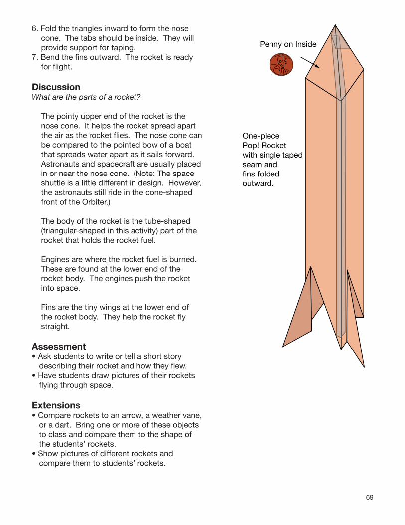
69
6. Fold the triangles inward to form the nose cone. The tabs should be inside. They will provide support for taping.
7. Bend the fi ns outward. The rocket is ready for fl ight.
DiscussionWhat are the parts of a rocket?
The pointy upper end of the rocket is the nose cone. It helps the rocket spread apart the air as the rocket fl ies. The nose cone can be compared to the pointed bow of a boat that spreads water apart as it sails forward. Astronauts and spacecraft are usually placed in or near the nose cone. (Note: The space shuttle is a little different in design. However, the astronauts still ride in the cone-shaped front of the Orbiter.)
The body of the rocket is the tube-shaped (triangular-shaped in this activity) part of the rocket that holds the rocket fuel.
Engines are where the rocket fuel is burned. These are found at the lower end of the rocket body. The engines push the rocket into space.
Fins are the tiny wings at the lower end of the rocket body. They help the rocket fl y straight.
Assessment• Ask students to write or tell a short story
describing their rocket and how they fl ew.• Have students draw pictures of their rockets
fl ying through space.
Extensions• Compare rockets to an arrow, a weather vane,
or a dart. Bring one or more of these objects to class and compare them to the shape of the students’ rockets.
• Show pictures of different rockets and compare them to students’ rockets.
One-piecePop! Rocketwith single taped seam andfins folded outward.
Penny on InsideIN
GOD WETRUST
LIBERTY
2008D

70
Three-Piece Pop! Rocket

71
Cut
on
solid
line
s.Fo
ld d
ashe
d li
nes
Fold fins outward. All other folds inward.
Fin FinFin
One-Piece Pop! Rocket
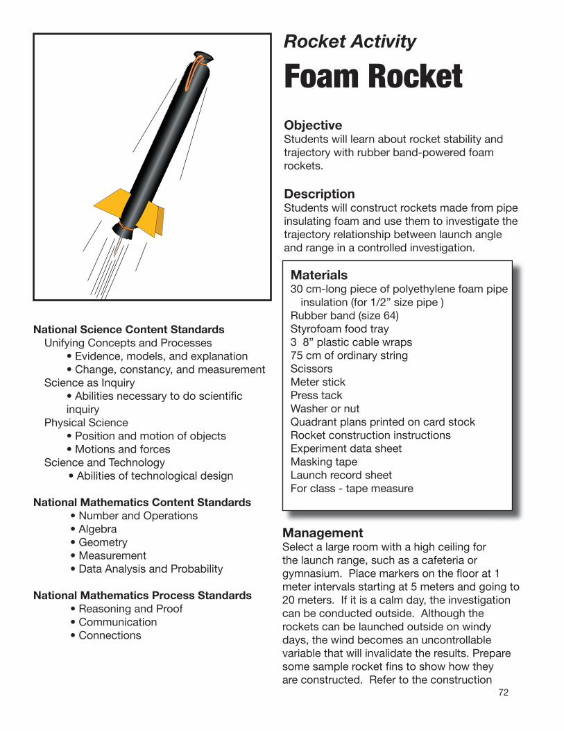
72
Rocket Activity
Foam RocketObjectiveStudents will learn about rocket stability and trajectory with rubber band-powered foam rockets.
DescriptionStudents will construct rockets made from pipe insulating foam and use them to investigate the trajectory relationship between launch angle and range in a controlled investigation.
Materials 30 cm-long piece of polyethylene foam pipe insulation (for 1/2” size pipe )Rubber band (size 64)Styrofoam food tray3 8” plastic cable wraps75 cm of ordinary stringScissorsMeter stickPress tackWasher or nutQuadrant plans printed on card stockRocket construction instructionsExperiment data sheetMasking tapeLaunch record sheetFor class - tape measure
National Science Content StandardsUnifying Concepts and Processes • Evidence, models, and explanation • Change, constancy, and measurementScience as Inquiry • Abilities necessary to do scientifi c
inquiryPhysical Science • Position and motion of objects • Motions and forcesScience and Technology
• Abilities of technological design
National Mathematics Content Standards• Number and Operations• Algebra• Geometry• Measurement• Data Analysis and Probability
National Mathematics Process Standards• Reasoning and Proof• Communication• Connections
ManagementSelect a large room with a high ceiling for the launch range, such as a cafeteria or gymnasium. Place markers on the fl oor at 1 meter intervals starting at 5 meters and going to20 meters. If it is a calm day, the investigation can be conducted outside. Although the rockets can be launched outside on windy days, the wind becomes an uncontrollable variable that will invalidate the results. Prepare some sample rocket fi ns to show how they are constructed. Refer to the construction
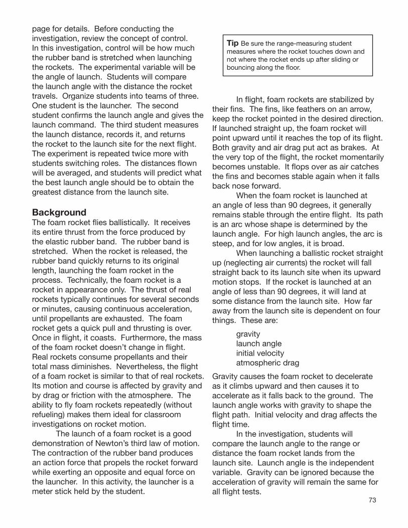
73
page for details. Before conducting the investigation, review the concept of control. In this investigation, control will be how much the rubber band is stretched when launching the rockets. The experimental variable will be the angle of launch. Students will compare the launch angle with the distance the rocket travels. Organize students into teams of three. One student is the launcher. The second student confirms the launch angle and gives the launch command. The third student measures the launch distance, records it, and returns the rocket to the launch site for the next flight. The experiment is repeated twice more with students switching roles. The distances flown will be averaged, and students will predict whatthe best launch angle should be to obtain the greatest distance from the launch site.
BackgroundThe foam rocket flies ballistically. It receives its entire thrust from the force produced by the elastic rubber band. The rubber band is stretched. When the rocket is released, the rubber band quickly returns to its original length, launching the foam rocket in the process. Technically, the foam rocket is a rocket in appearance only. The thrust of real rockets typically continues for several seconds or minutes, causing continuous acceleration, until propellants are exhausted. The foam rocket gets a quick pull and thrusting is over. Once in flight, it coasts. Furthermore, the massof the foam rocket doesn’t change in flight. Real rockets consume propellants and their total mass diminishes. Nevertheless, the flight of a foam rocket is similar to that of real rocketsIts motion and course is affected by gravity andby drag or friction with the atmosphere. The ability to fly foam rockets repeatedly (without refueling) makes them ideal for classroom investigations on rocket motion. The launch of a foam rocket is a good demonstration of Newton’s third law of motion. The contraction of the rubber band produces an action force that propels the rocket forward while exerting an opposite and equal force on the launcher. In this activity, the launcher is a meter stick held by the student.
Tip Be sure the range-measuring student measures where the rocket touches down and not where the rocket ends up after sliding or bouncing along the floor.
In flight, foam rockets are stabilized by their fins. The fins, like feathers on an arrow, keep the rocket pointed in the desired direction. If launched straight up, the foam rocket will point upward until it reaches the top of its flight. Both gravity and air drag put act as brakes. At the very top of the flight, the rocket momentarily becomes unstable. It flops over as air catches
the fins and becomes stable again when it falls back nose forward. When the foam rocket is launched at an angle of less than 90 degrees, it generally remains stable through the entire flight. Its path is an arc whose shape is determined by the launch angle. For high launch angles, the arc is steep, and for low angles, it is broad. When launching a ballistic rocket straight up (neglecting air currents) the rocket will fall straight back to its launch site when its upward motion stops. If the rocket is launched at an angle of less than 90 degrees, it will land at some distance from the launch site. How far away from the launch site is dependent on four things. These are:
gravity launch angle initial velocity atmospheric drag
. Gravity causes the foam rocket to decelerate as it climbs upward and then causes it to
accelerate as it falls back to the ground. The launch angle works with gravity to shape the flight path. Initial velocity and drag affects the flight time. In the investigation, students will
compare the launch angle to the range or distance the foam rocket lands from the launch site. Launch angle is the independent variable. Gravity can be ignored because the acceleration of gravity will remain the same for all flight tests.

74
o75
o60
o45
o30
o15
o15
Launch angle vs. range for rockets with the same initial launch velocity
Atmospheric drag can be ignoredbecause the same rocket will be flown repeatedly. Although students will not know the initial velocity, they will control for it by stretching the rubber band the same amount for each flight. The dependent variable in the experiment is the distance the rocket travels. Assuming student teams are careful in their control of launch angles and in the stretching of the launch band, they will observe that their farthest flights will come from launches with an angle of 45 degrees. They will also observe that launches of 30 degrees, for example, will produce the same range as launches of 60 degrees. Twenty degrees will produce the same result as 70 degrees, etc. (Note: Range distances will not be exact because of slight differences in launching even when teams are very careful to be consistent. However, repeated launches can be averaged so that the ranges more closely agree with the illustration.
Procedures Constructing a Foam Rocket1. Using scissors, cut one 30-cm length of pipe
foam for each team.2. Cut four equally spaced slits at one end of
the tube. The slits should be about 8 to 10 cm long. The fins will be mounted through these slits.
3. Tie a string loop that is about 30 cm long. 4. Slip one end of a cable wrap through the
string loop and through the rubber launch band.
Launch string loop
Plastic cable wrap Internal plastic cable wrap
Plastic cable wrap
Launch rubber band
Join the cable wrap to form a loop and tighten it down to a circle approximately 1 to 2 cm in diameter. The end of the wrap can be trimmed off with scissors or left.
5. Thread the cable wrap with string and rubber launch band through the hole in the foam tube. The string should stick out the rear end of the rocket and the rubber band out the nose. Position the plastic loop about 3 cm back from the nose.
6. Tighten the second cable wrap securely around the nose of the rocket. It should be positioned so that the cable wrap loop inside the rocket is unable to be pulled out the nose when the rubber band is stretched. Caution students not to pull on the string. The string should only be pulled during launches when the rubber band is held from the other end. Trim off the excess cable wrap end.
7. Cut fin pairs from the foam food tray or stiff cardboard. Refer to the fin diagram.
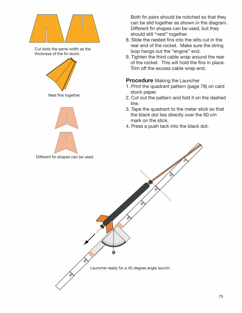
75
Both fin pairs should be notched so that they can be slid together as shown in the diagram. Different fin shapes can be used, but they should still “nest” together.
8. Slide the nested fins into the slits cut in the rear end of the rocket. Make sure the string loop hangs out the “engine” end.
9. Tighten the third cable wrap around the rear of the rocket. This will hold the fins in place. Trim off the excess cable wrap end.
Procedure Making the Launcher1. Print the quadrant pattern (page 78) on card
stock paper.2. Cut out the pattern and fold it on the dashed
line. 3. Tape the quadrant to the meter stick so that
the black dot lies directly over the 60 cm mark on the stick.
4. Press a push tack into the black dot.
Cut slots the same width as the thickness of the fin stock.
Nest fins together.
Different fin shapes can be used.
0
10
20304050
6070
80
90
80
50
40
30
10
20
Launcher ready for a 45-degree angle launch.
90

76
5. Tie a string to the push tack and hang a small weight, such as a nut or a washer, on the string. The weight should swing freely.
6. Refer to the diagram to see how the launcher is used.
Discussion• Why didn’t the experiment protocol call for
launching at 0 and 90 degrees? Assuming a perfect launch, a rocket launched
straight upwards should return to the launch pad. Any variation in the impact site will be due to air currents and not to the launch angle. A rocket launched horizontally will travel only as long as the time it takes to drop to the floor.
• Shouldn’t the rocket be launched from the floor for the experiment?
Yes. However, it is awkward to do so. Furthermore, student teams will be measuring the total distance the rocket travels, and consistently launching from above the floor will not significantly affect the outcome.
Assessment• Have student teams submit their completed
data sheets with conclusions.• Have students write about potential practical
uses for the foam rocket (e.g., delivering messages).
Extensions• For advanced students, the following
equation can be used for estimating ranges. (g is the acceleration of gravity on Earth)
Range = sin 2Ag
Vo = Initial Velocityg = 9.8 meters/second2
A = Launch Angle
Vo
Students will have to determine initial velocity. If available, an electronic photogate (science lab probeware) with timer can be used for determining the initial velocity. Otherwise, challenge students to devise a method for estimating initial velocity. One approach might be to launch the rocket horizontally from a tabletop and measure the horizontal distance the rocket travels as it falls to the floor. Using a stopwatch, measure the time the rocket takes to reach the floor. If the rocket takes 0.25 seconds to reach the floor and traveled 3 meters horizontally while doing so, multiply 3 meters by 4. The initial velocity will be 12 meters per second. Students should repeat the measurement several times and average the data to improve their accuracy. (This method assumes no slowing of the rocket in flight due to air drag.)
• Different kinds of fins can be constructed for the foam rocket. Try creating a space shuttle orbiter or a future rocket plane for exploring the atmosphere of other planets.

77
Cut four slits 8 cm long. 1
Cut out fins with notches.
Build a Foam Rocket
30 cm
Cable wrap loop
Rubber band
Slip string, cable wrap loop, and rubber band inside.
36
Close off end with cable wrap (tight!).
Close off end with cable wrap (tight!)
Slide fins into slits.
Ready for flight!
4
7
8
.
String
Join 30 cm string loop and rubber band with cable wrap.
2
Slide fins together.
5

78
010
2030
40
50
6070
8090
Fold
on
das
hed
line
. L
ay fo
ld o
n up
per
ed
ge o
f met
er s
tick
and
wra
p p
aper
aro
und
to
the
othe
r si
de.
The
bla
ck d
ot o
f th
e p
rotr
acto
r sh
ould
be
pla
ced
on
the
60 c
m m
ark
of t
he
stic
k. T
ape
end
s to
hol
d t
he p
rotr
acto
r in
pla
ce.
60 cm (or 24 inches)
Launcher Quadrant Pattern(Actual Size)

79
Rocket Range Experiment
Team Member Names:
1. Assign duties for your team. You will need the following positions: Launch Director, Launcher, and Range Officer. (Team members will switch jobs later.)
2. First Launch:Launcher - Attach the rocket to the launcher and pull back on string until its tail reaches the 60-cm mark. Tilt the launcher until it is pointing upwards at a angle of between 10 and 80 degrees. Release the rocket when the launch command is given. Launch Director - Record the angle on the data table. Give the launch command. Record the distance the rocket travels.Range Officer - Measure the distance from the launcher to where the rocket hits the floor (not where it slides or bounces to). Report the distance to the launch director and return the rocket to the launcher for the next launch.
3. Repeat the launch procedures four more times but for different angles of from 10 and 80 degrees.
4. Run the entire experiment twice more but switch jobs each time. Use different launch angles.
5. Compare your data for the three experiments.
LaunchAngle Distance
Data Table 1
LaunchAngle Distance
Data Table 3
LaunchAngle Distance
Data Table 2
From your data, what launch angle should you use to achieve the greatest distance from the launch site? Test your conclusion.
Why didn’t the instructions ask you to test for 0 and 90 degrees?

80
Rocket Activity
Launch Altitude
TrackerObjectiveUsing a simple altitude tracker and basic mathematics, students will indirectly measure the altitude achieved by the rockets they construct.
DescriptionDetermining the altitude reached by a rocket is a relatively simple process using a hand-held tracking device. The device is a sighting tube with a marked water level that permits measurement of the inclination of the tube. Using simple mathematics, students will calculate the altitude of the rocket. With two trackers in different locations, accuracy of the estimates can be improved.
MaterialsTracker (see separate instructions)Tape measureTangent tableData sheetCalculator (optional)
National Science Content StandardsPhysical Science • Position and motion of objects • Motions and forcesScience and Technology
• Understanding about science and technology
National Mathematics Content Standards• Number and Operations• Geometry• Measurement• Data Analysis and Probability
National Mathematics Process Standards• Problem Solving• Reasoning and Proof• Communication• Connections• Representations
ManagementAltitude trackers are easy to construct. They are rugged and can be used again and again. Use them for altitude measurements with the High-Power Air Rockets and the Project X-51 activities. These rockets are capable of fl ights between 50 and 100 meters high. Be sure students understand how to sight rockets with the tracker. If you have a fl agpole or tall building near the launch site, have students practice taking measurements of the angle between the ground and the top of the pole or to one of the upper corners of the building. When students are comfortable using the

81
A
b
a = tan A (b)
a
46
47
48
49
50
51
52
53
54
55
56
57
58
59
60
61
62
63
64
65
66
67
68
69
70
71
72
73
74
75
76
77
78
79
80
81
82
83
84
85
86
87
88
89
90
---
1.036
1.072
1.111
1.150
1.192
1.235
1.280
1.327
1.376
1.428
1.483
1.540
1.600
1.664
1.732
1.804
1.881
1.963
2.050
2.145
2.246
2.356
2.475
2.605
2.747
2.904
3.078
3.271
3.487
3.732
4.011
4.331
4.705
5.145
5.671
6.314
7.115
8.144
9.514
11.43
14.30
19.08
28.64
57.29
---
---
.0000
.0175
.0349
.0524
.0699
.0875
.1051
.1228
.1405
.1584
.1763
.1944
.2126
.2309
.2493
.2679
.2867
.3057
.3249
.3443
.3640
.3839
.4040
.4245
.4452
.4663
.4877
.5095
.5317
.5543
.5774
.6009
.6249
.6494
.6745
.7002
.7265
.7536
.7813
.8098
.8391
.8693
.9004
.9325
.9657
1.000
0
1
2
3
4
5
6
7
8
9
10
11
12
13
14
15
16
17
18
19
20
21
22
23
24
25
26
27
28
29
30
31
32
33
34
35
36
37
38
39
40
41
42
43
44
45
Angle Tangent Angle Tangent
tracker and consistent in measuring, they are ready to track rockets. Lay out a baseline from the launch site. Details for doing this are given in the procedures. A longer baseline provides better measurements than a shorter one. However, long baselines mean that your students will be spread out on the launch range. You may wish to enlist a teacher aid to help with supervision.
Background:Altitude tracking of small rockets is an exciting activity for students because it provides them with a way of estimating how high their rocket flies. The technique for doing this is relatively simple. The rocket is launched and a tracker, some distance away, sights the rocket and determines the angle between the ground and the rocket at the top of its flight. Using a simple formula, the altitude is calculated.
a (altitude) = tangent of A (angle) X b (baseline)
a = tan A (b)
To solve the formula, students look for the angle they measured on the tangent table. For example, the angle is 30 degrees. The tangent is 0.5774. They use that number in the equation. The baseline (distance from the launch pad to the tracker) is measured with a tape measure. In our example the distance is 25 meters.
a = 0.5774 X 25 m = 14.435 m
The altitude reached by the rocket is 14.435 meters.
Single station Tr- No Wind
acking
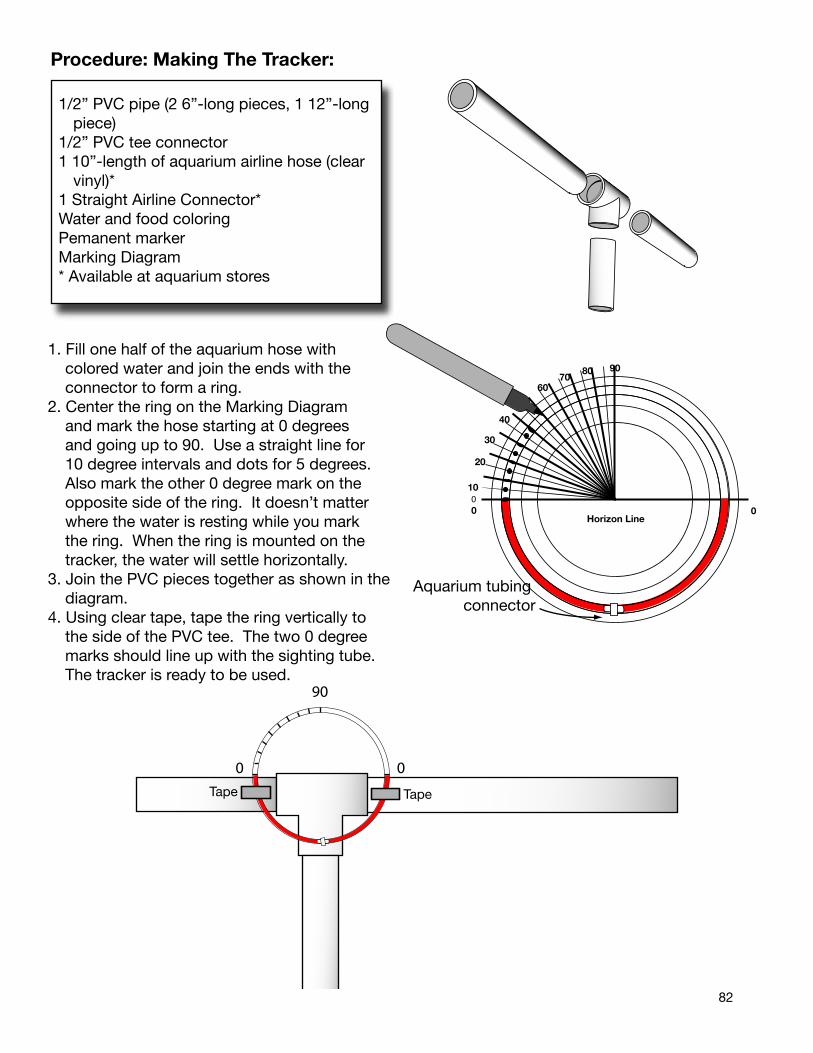
82
Procedure: Making The Tracker:
1/2” PVC pipe (2 6”-long pieces, 1 12”-longpiece)
1/2” PVC tee connector1 10”-length of aquarium airline hose (clear
vinyl)*1 Straight Airline Connector*Water and food coloringPemanent markerMarking Diagram* Available at aquarium stores
00 0
10
20
30
40
5060
7080 90
Horizon Line
00 0
10
20
30
40
5060
7080 90
Horizon Line
Aquarium tubing connector
Tape Tape
0
90
0
1. Fill one half of the aquarium hose with colored water and join the ends with the connector to form a ring.
2. Center the ring on the Marking Diagram and mark the hose starting at 0 degrees and going up to 90. Use a straight line for 10 degree intervals and dots for 5 degrees. Also mark the other 0 degree mark on the opposite side of the ring. It doesn’t matter where the water is resting while you mark the ring. When the ring is mounted on the tracker, the water will settle horizontally.
3. Join the PVC pieces together as shown in thediagram.
4. Using clear tape, tape the ring vertically to the side of the PVC tee. The two 0 degree marks should line up with the sighting tube. The tracker is ready to be used.

83
00 0
10
20
30
40
5060
7080 90
Horizon Line
00 0
10
20
30
40
5060
7080 90
Horizon Line
Aquarium tubing connector
Water Level Marking Diagram
Procedure Using the Tracker1. Select an open space for the launch. If the
wind is strong, position the launch pad up wind so that the wind will blow the rocket onthe fi eld when it falls back.
2. Measure out the longest baseline you can conveniently have for the size of the launch fi eld available. Align the baseline with the wind. (See note for using two tracking stations.)
3. Make sure the students at each station knowwhich rocket is about to launch. When the rocket is launched, the tracking students aimtheir trackers at the highest point in the fl ightof the rocket. The angles of the trackers are read from the water level and the data recorded. Have the students help each otherin reading the angle from the water level. Forgreater accuracy, have students average theirestimates. Calculations can be done back inthe classroom.
Notes Assuming perfect conditions, the rocket goes straight up from the launch pad. This creates
a right angle with Earth and the computed altitude should be accurate. However, altitude estimates for rockets that stray from the vertical will be less accurate. To minimize wind effects, two tracking stations can be used. Each are placed at equal distances from the launcher. The line connecting the two sites should be
parallel to the wind. The students at each site track the rocket. Assuming the wind causes
the rocket to drift over the up wind station, that tracker will get a higher angle than if the rocket
had climbed straight up. The student at the down wind station will get a lower angle. Their
estimates are averaged together to correct for wind effects. The diagram on the next page shows how the two tracking stations coordinate to improve altitude estimates.
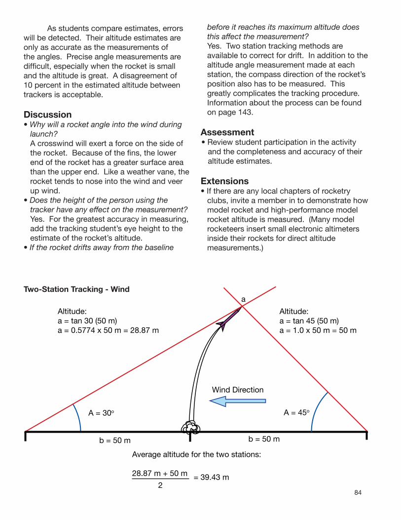
84
a1
A1 b = 50 m
A = 30o
A2b = 50 m
Altitude:a = tan 30 (50 m)a = 0.5774 x 50 m = 28.87 m
aTwo-Station Tracking - Wind
Altitude:a = tan 45 (50 m)a = 1.0 x 50 m = 50 m
As students compare estimates, errors will be detected. Their altitude estimates are only as accurate as the measurements of the angles. Precise angle measurements are difficult, especially when the rocket is small and the altitude is great. A disagreement of 10 percent in the estimated altitude between trackers is acceptable.
Discussion• Why will a rocket angle into the wind during
launch? A crosswind will exert a force on the side of
the rocket. Because of the fins, the lower end of the rocket has a greater surface area than the upper end. Like a weather vane, the rocket tends to nose into the wind and veer up wind.
• Does the height of the person using the tracker have any effect on the measurement?
Yes. For the greatest accuracy in measuring, add the tracking student’s eye height to the estimate of the rocket’s altitude.
• If the rocket drifts away from the baseline
before it reaches its maximum altitude does this affect the measurement?
Yes. Two station tracking methods are available to correct for drift. In addition to the altitude angle measurement made at each station, the compass direction of the rocket’s position also has to be measured. This greatly complicates the tracking procedure. Information about the process can be found on page 143.
Assessment• Review student participation in the activity
and the completeness and accuracy of their altitude estimates.
Extensions• If there are any local chapters of rocketry
clubs, invite a member in to demonstrate how model rocket and high-performance model rocket altitude is measured. (Many model rocketeers insert small electronic altimeters inside their rockets for direct altitude measurements.)
Wind Direction
A = 45o
Average altitude for the two stations:
28.87 m + 50 m
2= 39.43 m

85
46 1.036
47 1.072
48 1.111
49 1.150
50 1.192
51 1.235
52 1.280
53 1.327
54 1.376
55 1.428
56 1.483
57 1.540
58 1.600
59 1.664
60 1.732
61 1.804
62 1.881
63 1.963
64 2.050
65 2.145
66 2.246
67 2.356
68 2.475
69 2.605
70 2.747
71 2.904
72 3.078
73 3.271
74 3.487
75 3.732
76 4.011
77 4.331
78 4.705
79 5.145
80 5.671
81 6.314
82 7.115
83 8.144
84 9.514
85 11.43
86 14.30
87 19.08
88 28.64
89 57.29
90 ---
--- ---
Angle Tangent Angle Tangent0 .0000
1 .0175
2 .0349
3 .0524
4 .0699
5 .0875
6 .1051
7 .1228
8 .1405
9 .1584
10 .1763
11 .1944
12 .2126
13 .2309
14 .2493
15 .2679
16 .2867
17 .3057
18 .3249
19 .3443
20 .3640
21 .3839
22 .4040
23 .4245
24 .4452
25 .4663
26 .4877
27 .5095
28 .5317
29 .5543
30 .5774
31 .6009
32 .6249
33 .6494
34 .6745
35 .7002
36 .7265
37 .7536
38 .7813
39 .8098
40 .8391
41 .8693
42 .9004
43 .9325
44 .9657
45 1.000
AltitudentRocket Angle Tangent
Altitude Tracking Data Sheet
Tracker Name:
Baseline Length:
1. Measure the angle to the highest point the rocket reaches.2. Record the angle.3. Look up the tangent for the angle. Record that number.4. Multiply the tangent number times the length of the baseline. The answer is the altitude the rocket reached.
Calculations:

86
Rocket Activity
High-Power Paper Rocket LauncherObjectiveConstruct a launcher for use with the High-Power Paper Rocket activity.
DescriptionUsing air pressure, large paper rockets can be launched to altitudes of between 50 and 100 meters. The launcher is a chamber in which air is pressurized with a bicycle pump or small electric compressor. Paper rockets are slipped over a launch rod tube. A lever-valve releases the air that propels the rocket. The launch rod can be tilted to various angles to launch vertically or horizontally. The launcher is easy to construct and requires few skills. The parts are available from a hardware or plumbing supply store and are inexpensive.
National Science Content StandardsPhysical Science • Position and motion of objects • Motions and forcesScience and Technology
• Abilities of technological design
National Mathematics Content Standards
• Measurement
National Mathematics Process Standards• Connections
MaterialsRefer to the shopping list (see page 90)SawDrillBicycle pump or small electric compressor
ManagementOne launcher is suffi cient for an entire class, and the launcher can be used year after year. The launcher is easy to construct and will take about 30-60 minutes to complete. Cementing the pieces is a quick operation, but the cement should be allowed to set overnight. When cementing, be sure to have adequate ventilation. A window fan blowing over the work area is advisable. Use eye protection when cutting pipe and cementing pieces.
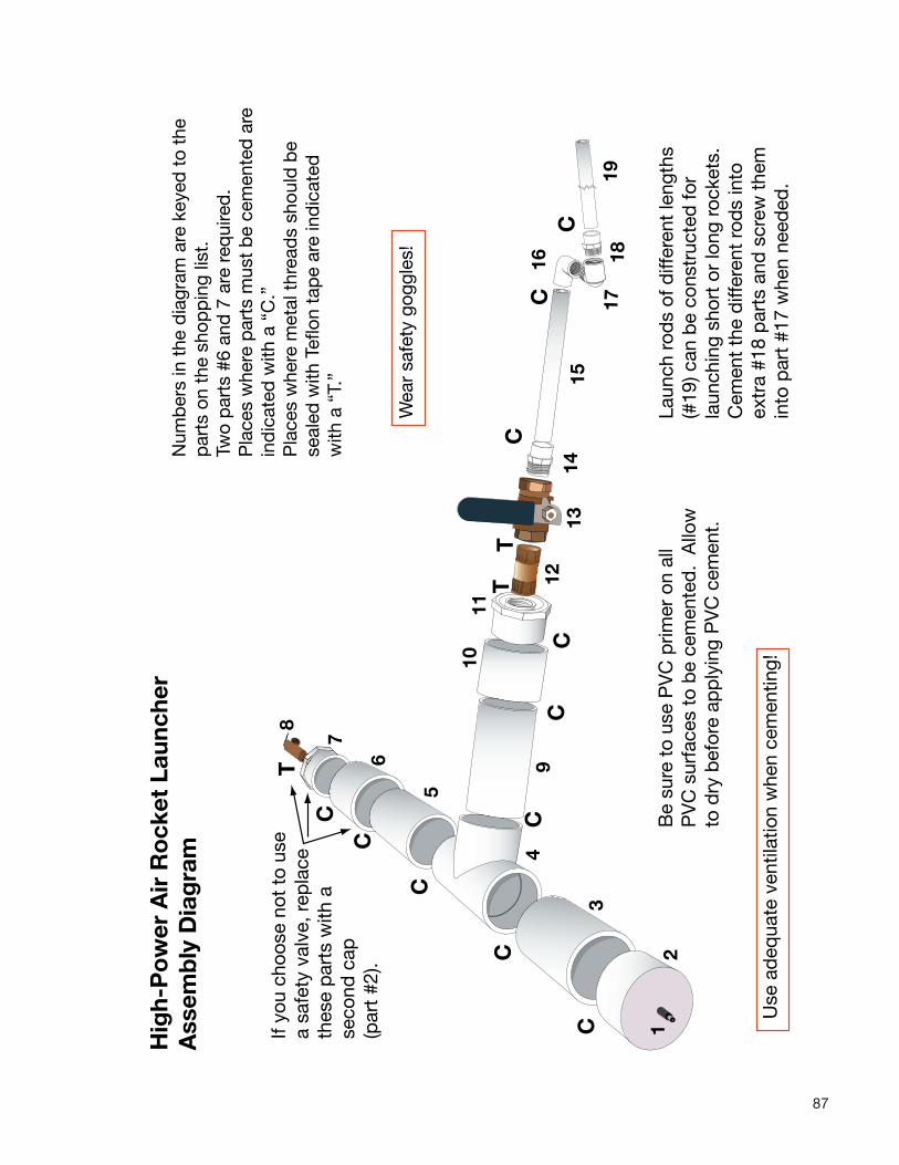
87
Num
ber
s in
the
dia
gram
are
key
ed t
o th
e p
arts
on
the
shop
pin
g lis
t.Tw
o p
arts
#6
and
7 a
re r
equi
red
.P
lace
s w
here
par
ts m
ust
be
cem
ente
d a
re
ind
icat
ed w
ith a
“C
.”P
lace
s w
here
met
al t
hrea
ds
shou
ld b
ese
aled
with
Tef
lon
tap
e ar
e in
dic
ated
w
ith a
“T.
”
12
3
4
5
6
10
7
C
C
C
C
C
CC
C
11
8
912
1314
15
16
1718
19
C
CC
T
TT
If yo
u ch
oose
not
to
use
a sa
fety
val
ve, r
epla
ce
thes
e p
arts
with
a
seco
nd c
ap
(par
t #2
).
Be
sure
to
use
PV
C p
rimer
on
all
PV
C s
urfa
ces
to b
e ce
men
ted
. A
llow
to d
ry b
efor
e ap
ply
ing
PV
C c
emen
t.
Use
ad
equa
te v
entil
atio
n w
hen
cem
entin
g!
Laun
ch r
ods
of d
iffer
ent
leng
ths
(#19
) can
be
cons
truc
ted
for
laun
chin
g sh
ort
or lo
ng r
ocke
ts.
Cem
ent
the
diff
eren
t ro
ds
into
ex
tra
#18
par
ts a
nd s
crew
the
m
into
par
t #1
7 w
hen
need
ed.
Hig
h-P
ow
er A
ir R
ock
et L
aunc
her
Ass
emb
ly D
iag
ram
Wea
r sa
fety
gog
gles
!

88
If you do not have the tools to construct the launcher, a school volunteer should have them and may be willing to do the entire construction job for you. The instructions include diagrams to make assembly of the parts easy. The assembly diagram below has numbers for each of the parts that are keyed to numbers on the shopping list. Take the shopping list to the hardware or plumbing supply store and the staff can help you select the parts. The 2-inch diameter tube may be available in a 5-foot length. You will need two or three of the 1/2-inch tubes. The tire valve can be obtained at an auto parts store. Select a valve with a long rubber-coated stem.
Assembly Instructions 1. Drill a hole in the center of one of the 2-
inch caps (part #2). The hole should be just smaller than the diameter of the tire valve stem.
2. Remove the stem cap and jam the stem into the hole from the inside. Push it in as far as it goes. It is important to get a tight seal.
3. Cut the lengths of 2” pipe. Cut two pieces 8” long (parts #3, 5) and 1 piece 15” long (part #7). Clean the pipes and remove any burrs from the cutting process.
4. Cement parts #3 and 5 to the tee (part #4) as shown in the diagram. When cementing, the parts must first be primed with clear primer. This prepares the surfaces to be joined for bonding. Coat the surfaces that will be cemented. There is a brush inside the primer can lid. Let the primer dry before cementing. Remember to have adequate ventilation and wear eye protection!
5. Coat the primed surfaces with cement (ends of tubes and inside of the tee). There is a brush inside the cement can lid. Quickly shove the tubes into the tee as far as they go. Use a twisting motion for a better bond.
6. Repeat the cementing process with the 2” cap with the tire valve installed (part #2).
7. Cement the first 2” connector to the open end of piece #5. Cement the 2” to 3/4” flush bushing to the connector.
8. Install the safety valve into the flush bushing and seal it with Teflon tape. Do not use pipe joint compound. Be careful to align the threads so as not to strip the PVC threads.
9. Cement part #9 into the remaining opening of the tee.
8. Cement the remaining coupling (part #10) on to the end of part #9.
9. Cement the remaining 2” to 3/4” flush bushing into the open end of the coupling (part#10).
10. Thread the nipple into the threaded opening of part #10. Use Teflon tape to seal the threads to prevent air leaks.
11. Wrap tape on the other end of the nipple and attach the valve (part #13). The valve should be positioned so that when the lever is pulled down, it pulls towards the back (towards the tee).
12. Lightly screw part #14 into the other end of the valve. This part should not be sealed with tape. It is the beginning of the launch rod and can be removed for storage purposes.
13. Cement part #15 into the non-threaded end of part#14.
14. Cement part #16 on to the other end of the tube (part #15).
15. Join parts #16 and #17 by threading them together. Do not join them tightly.
16. Cement the ends of the three launch rods (part #19) into the three 1/2” to 1/2” adapters (part #18). Pick one of the launch rods and screw it into part #17.
After allowing time for the cement to set, the launcher is ready.
Notes • The launcher can be used for many years.
Store it in a cool place. Be careful not to drop it. The plastic will crack if treated roughly. If you notice any cracks, discard the launcher. The metal parts and the launch rod can be saved and used for a new launcher.
DO NOT try to remove any pieces that have been cemented. If pieces are cemented improperly, discard them. The process of
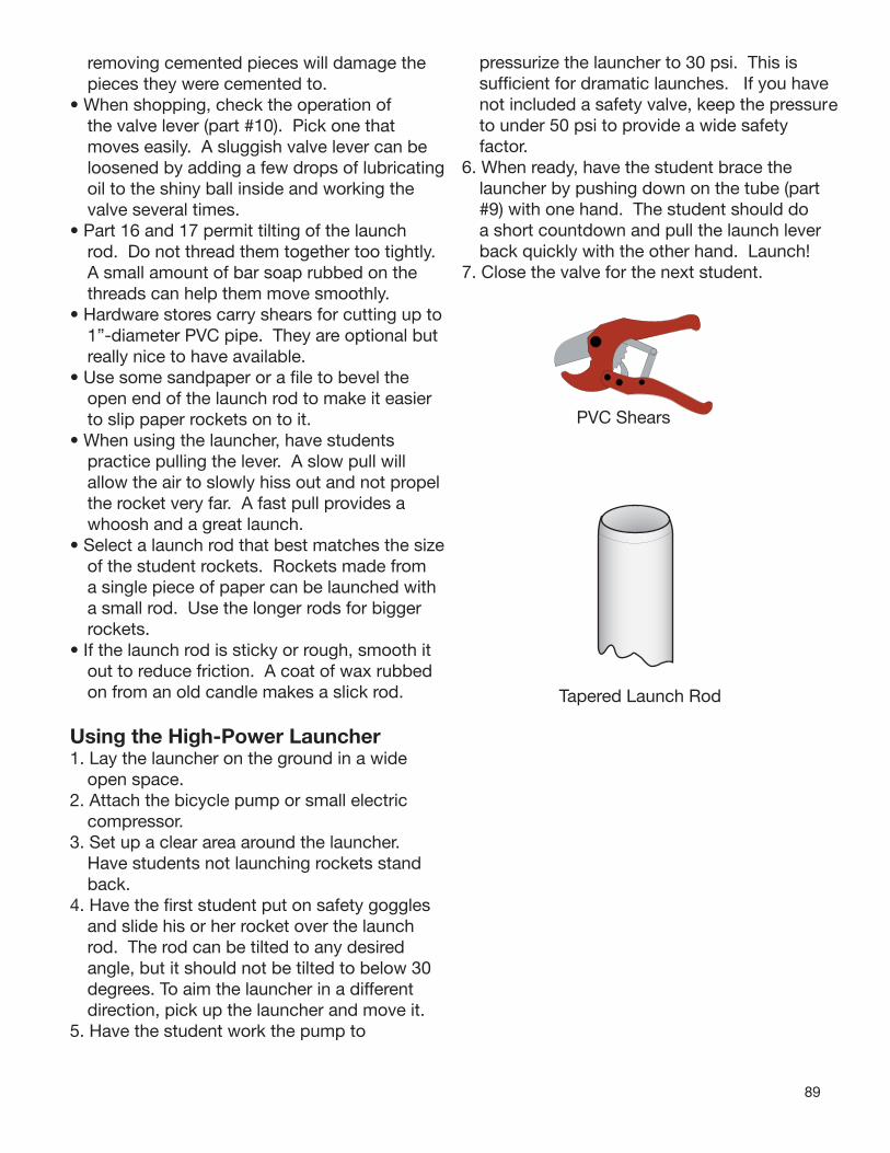
89
removing cemented pieces will damage the pieces they were cemented to.
• When shopping, check the operation of the valve lever (part #10). Pick one that moves easily. A sluggish valve lever can be loosened by adding a few drops of lubricating oil to the shiny ball inside and working the valve several times.
• Part 16 and 17 permit tilting of the launch rod. Do not thread them together too tightly. A small amount of bar soap rubbed on the threads can help them move smoothly.
• Hardware stores carry shears for cutting up to 1”-diameter PVC pipe. They are optional but really nice to have available.
• Use some sandpaper or a file to bevel the open end of the launch rod to make it easier to slip paper rockets on to it.
• When using the launcher, have students practice pulling the lever. A slow pull will allow the air to slowly hiss out and not propel the rocket very far. A fast pull provides a whoosh and a great launch.
• Select a launch rod that best matches the size of the student rockets. Rockets made from a single piece of paper can be launched with a small rod. Use the longer rods for bigger rockets.
• If the launch rod is sticky or rough, smooth it out to reduce friction. A coat of wax rubbed on from an old candle makes a slick rod.
Using the High-Power Launcher1. Lay the launcher on the ground in a wide
open space. 2. Attach the bicycle pump or small electric
compressor.3. Set up a clear area around the launcher.
Have students not launching rockets stand back.
4. Have the first student put on safety goggles and slide his or her rocket over the launch rod. The rod can be tilted to any desired angle, but it should not be tilted to below 30 degrees. To aim the launcher in a different direction, pick up the launcher and move it.
5. Have the student work the pump to
pressurize the launcher to 30 psi. This is sufficient for dramatic launches. If you have not included a safety valve, keep the pressure to under 50 psi to provide a wide safety factor.
6. When ready, have the student brace the launcher by pushing down on the tube (part #9) with one hand. The student should do a short countdown and pull the launch lever back quickly with the other hand. Launch!
7. Close the valve for the next student.
PVC Shears
Tapered Launch Rod
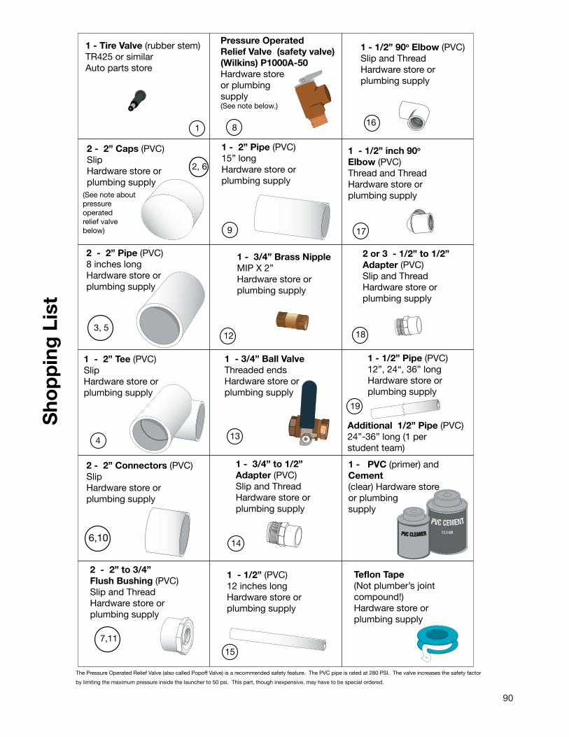
90
1 - Tire Valve (rubber stem)TR425 or similarAuto parts store
2 - 2” Caps (PVC)SlipHardware store or plumbing supply
2 - 2” Pipe (PVC)8 inches longHardware store or plumbing supply
1 - 2” Tee (PVC)SlipHardware store or plumbing supply
2 - 2” to 3/4”Flush Bushing (PVC) Slip and ThreadHardware store or plumbing supply
Sho
pp
ing
Lis
t
(See note about pressure operatedrelief valve below)
2, 6
1
4
7,11
2 - 2” Connectors (PVC)SlipHardware store or plumbing supply
6,10
3, 5
The Pressure Operated Relief Valve (also called Popof
by limiting the maximum pressure inside the launcher
f Va
to 5
e is rate
e speci
lve) is a recommended safety feature. The PVC pip
0 psi. This part, though inexpensive, may have to b
d at 280 PSI. The valve increases the safety factor
al ordered.
Ad24stu
1 -Ce(clor su
T(c
p
19
1
1 - 3/4” Brass NippleMIP X 2”Hardware store or plumbing supply
1 - 3/4” Ball ValveThreaded endsHardware store or plumbing supply
1 - 3/4” to 1/2”Adapter (PVC)Slip and ThreadHardware store or plumbing supply
1 - 1/2” (PVC)12 inches longHardware store or plumbing supply
12
15
13
14
1 - 1/2” Pipe (PVC)12”, 24“, 36” longHardware store or plumbing supply
ditional 1/2” Pipe (PVC)”-36” long (1 per dent team)
CLEAR
PVC CEMENTPVC CLEANER
PVC (primer) andment
ear) Hardware store plumbing pply
eflon Tape Not plumber’s joint ompound!)
Hardware store or lumbing supply
8
2 or 3 - 1/2” to 1/2”Adapter (PVC)Slip and ThreadHardware store or plumbing supply
1 - 1/2” 90o Elbow (PVC)Slip and ThreadHardware store or plumbing supply
16
1ETH
1 - 2” Pipe (PVC)15” longHardware store or plumbing supply
- 1/2” inch 90o
lbow (PVC)hread and Threadardware store or
plumbing supply
17
Pressure OperatedRelief Valve (safety valve)(Wilkins) P1000A-50Hardware store or plumbing supply(See note below.)
8
9
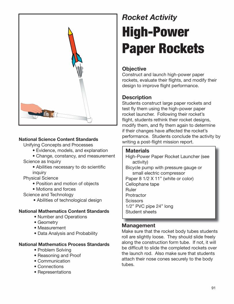
91
Rocket Activity High-Power Paper Rockets ObjectiveConstruct and launch high-power paper rockets, evaluate their fl ights, and modify their design to improve fl ight performance.
DescriptionStudents construct large paper rockets and test fl y them using the high-power paper rocket launcher. Following their rocket’s fl ight, students rethink their rocket designs, modify them, and fl y them again to determine if their changes have affected the rocket’s performance. Students conclude the activity bywriting a post-fl ight mission report.
MaterialsHigh-Power Paper Rocket Launcher (see
activity)Bicycle pump with pressure gauge or
small electric compressorPaper 8 1/2 X 11” (white or color)Cellophane tapeRulerProtractorScissors1/2” PVC pipe 24” longStudent sheets
National Science Content StandardsUnifying Concepts and Processes • Evidence, models, and explanation • Change, constancy, and measurementScience as Inquiry • Abilities necessary to do scientifi c
inquiryPhysical Science • Position and motion of objects • Motions and forcesScience and Technology
• Abilities of technological design
National Mathematics Content Standards• Number and Operations• Geometry• Measurement• Data Analysis and Probability
National Mathematics Process Standards• Problem Solving• Reasoning and Proof• Communication• Connections• Representations
ManagementMake sure that the rocket body tubes students roll are slightly loose. They should slide freely along the construction form tube. If not, it will be diffi cult to slide the completed rockets over the launch rod. Also make sure that students attach their nose cones securely to the body tubes.

92
Two sheets of paper are suffi cient for making a rocket. If colored paper is used, students can trade scraps with each other to have different colored nose cones and fi ns.
BackgroundHigh-power paper rockets are merely a large version of the paper rockets constructed in the 3, 2, 1, Puff! activity presented earlier. The main difference is in how the rockets are launched. These rockets are propelled by the air rocket launcher constructed in the previous activity. A much more powerful blast of air is achievable than with lung power through a straw. The launcher is like an air-powered cannon. However, the rocket surrounds the launch rod (similar to a cannon barrel). High-pressure air fi lls the rocket. If the rocket were fi rmly attached to the rod, the nose cone and the forward end of the rocket would blow apart. Instead, the rocket begins sliding along the rod as it continues to fi ll with air. Immediately after clearing the end of the rod, air inside the rocket expands backward out the lower end. The action-reaction effect (Newton’s third law) adds thrust to the already moving rocket. If the rocket is well-designed and constructed, fl ights of more than 100 meters are possible. The primary determining factor for performance is drag or friction with the air. Rockets with very big fl oppy fi ns have a great amount of drag, and fl ights are usually short. Very squat nose cones also increase drag. The idea is to design a rocket that is streamlined so that it slices cleanly through the air. Through repeated fl ights, students discover that small and very straight fi ns are preferred along with long nose cones.
Tip Make sure students launch their rockets at the same angle and use the same pressure each time (experiment control).
Procedure Constructing the Rocket1. Begin construction by rolling a cylinder of
paper around the 1/2” PVC pipe. The paper can be rolled the long or short direction to make a tube 11 1/2” long or 8 1/2” long. Tape the seam.
2. Demonstrate how the nose cones are formed. Cut the half circle and curl its corners to form the cone shape. The round edge forms the base of the cone. The straight edge folds in the middle to form the apex as the sides overlap. Tape the seam.
3. Place the nose cone over the paper body tube (keep the PVC pipe inside for support). Fit the cone to the outside dimension of the body tube. Trim off the excess paper and tape the cone securely.
4. Cut rocket fi ns and tape them to the lower end of the body tube. The rocket is ready for launch.
5. Have students launch their rockets two or more times. Before the second launch, students should do something to modify their rockets to improve their fl ight performance. After their fl ights, they should record their observations on the mission report.
Discussion• How can air rockets be modifi ed to improve
their fl ight performance? There are several possible adjustments to the
air rocket design. How loose or tight the tube is in relation to the launch rod affects air fl ow. The size and shapes of the fi ns affect air drag. Having fi ns mounted straight on the body of the rocket also affects drag. The length of the cone, squat or slender, affects how the rocket slices through the air.
• Is it OK to change the fi ns and the nose cone at the same time?
Yes. However, it will not be possible to attribute improvements in fl ight performance to the changes that made a difference. Think of the design/redesign process as a controlled experiment where only one variable is changed at a time.
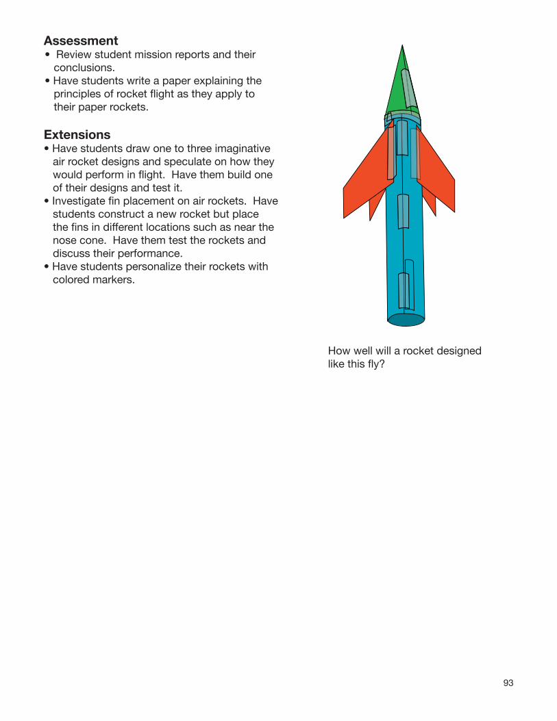
93
Assessment• Review student mission reports and their
conclusions.• Have students write a paper explaining the
principles of rocket fl ight as they apply to their paper rockets.
Extensions• Have students draw one to three imaginative
air rocket designs and speculate on how they would perform in fl ight. Have them build one of their designs and test it.
• Investigate fi n placement on air rockets. Have students construct a new rocket but place the fi ns in different locations such as near the nose cone. Have them test the rockets and discuss their performance.
• Have students personalize their rockets with colored markers.
How well will a rocket designed like this fl y?
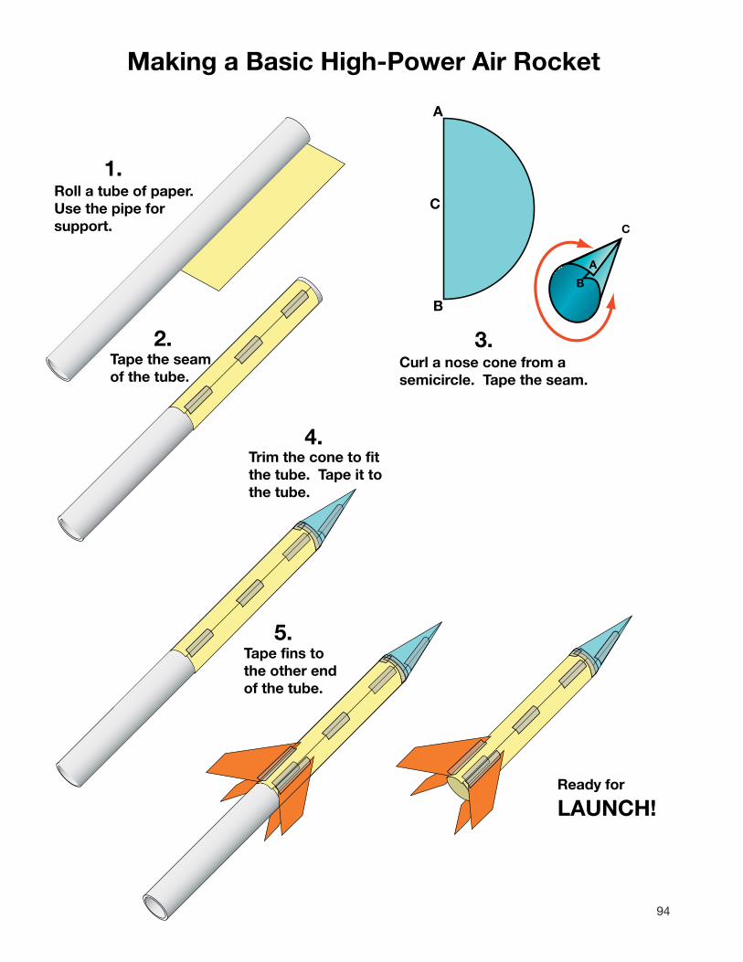
94
A
B
A
B
C
C
Roll aUse thsupport.
Curl a nose cone from a semicircle. Tape the seam.
Tape the seam of the tube.
Trim the cone to fit the tube. Tape it to the tube.
Tape fins tothe other endof the tube.
Ready for
LAUNCH!
2. 3.
4.
5.
Making a Basic Hi
1. tube of paper. e pipe for
gh-Power Air Rocket

95
Air Rocket Mission ReportFinal Rocket Design
Name: _________________________
Test Flight 1 Summary:
Body Tube Length: __________ cm
Nose Cone Length:__________ cm
Number of Fins:_____________
Area of 1 Fin: ______________ square cm
How far did the rocket travel? ____________________
Describe the flight of the rocket. (Did it fly straight, wobble, drop quickly to the ground, etc?)
Test Flight 2 Summary:
Body Tube Length: __________ cm
Nose Cone Length:__________ cm
Number of Fins:_____________
Area of 1 Fin: ______________ square cm
What did you do to improve the rocket?
Predict how far the rocket will fly. _________________
Describe the flight of the rocket.
How far did the rocket travel? ____________________
Did your improvements work? Why or why not?

96
Rocket Fin Design
Design your fin on the first graph.Estimate its area by counting the number of whole squares it covers. Look at the squares partially covered. Estimate how many whole squares they are equal to. Add the two numbers together.
Area =
__________square cm
Redesign your fin.
Area =
__________square cm

9797
Design your fin on the first graph.Estimate its area by counting the number of whole squares it covers. Look at the squares partially covered. Estimate how many whole squares they are equal to. Add the two numbers together.
Rocket Fin Design
Area =
__________square cm
Area =
__________square cm
Redesign your fin.
Rocket Activity
Rocket Wind
TunnelObjectiveStudents predict the performance of their air rockets by measuring their streamlining properties.
DescriptionAir rockets are placed inside a wind tunnel, and their resistance to the fl ow of air in the tunnel is measured in tenths of grams. The more streamlined the rocket designs are (less resistance to the air fl ow), the better their potential fl ight performance. Students will use data generated in the wind tunnel to help them design better rockets.
National Science Content StandardsUnifying Concepts and Processes • Evidence, models, and explanation • Change, constancy, and measurementScience as Inquiry • Abilities necessary to do scientifi c
inquiryPhysical Science • Position and motion of objects • Motions and forcesScience and Technology
• Abilities of technological design
National Mathematics Content Standards• Number and Operations• Measurement• Data Analysis and Probability
National Mathematics Process Standards• Problem Solving• Reasoning and Proof• Communication• Connections• Representations
MaterialsPaper concrete tube form (8” or 12" by 4’) Beam balance or electronic scale
(sensitive to 0.1 grams)Balance or some other weightThin wire coat hangerNail (about 16D by 3”)2 small screw eyesStringDuct tapeTransparency paper or clear cellophaneSmall electric fanNeedle-nose pliers and wire cutterBox cutterRulerToilet paper roll tubes - about 24Hot glueFlashlightAdhesive or gummed paper reinforcing
rings

98
Management:The wind tunnel should be constructed prior to the activity. It is simply a measurement tool students can use to evaluate the potential performance of their air rockets.
The cardboard cement form is available from large hardware stores. It generally comes in 8” and 12” diameters. You will need a strong fan to power the tunnel. The 12-inch tube provides students with more flexibility in their rocket designs. It permits fin spans of nearly 12 inches. The length of the lever arm will be determined by the diameter of the tube you use. If using an 8”-diameter tube, the length of the arm inside the tunnel will be 4” and the outside length (on the other side of the fulcrum) will be 1”. If using a 12”-tube, the dimensions should be 6” and 1”. When you use the tunnel, the lower end will have to be supported so that the air flowing through the tube has a clear pathway to leave the tube. The air flow is downward. An electronic balance is easier to use than a beam balance. However, the beam balance gives students good practice in measuring mass and adding measurements.
Toilet paper tubes glued together form air vanes. Install and glue them inside the top of the wind tunnel.
Cutaway view of the tunnel interior(The actual door should be smaller.)
The rocket is supported by the lever arm. The right side of the arm is held by the weight. Prior to testing, the scale is brought to balance. When the tunnel is operating, air drag on the rocket is transmitted by the lever arm to the weight. This unbalances the scale.
Adjusting the slide weights provides a measure of the force being exerted on the rocket.
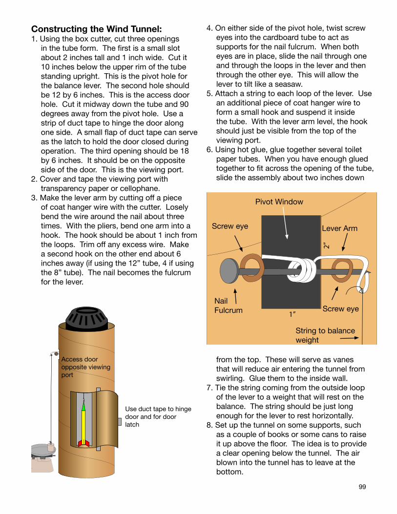
99
Constructing the Wind Tunnel:1. Using the box cutter, cut three openings
in the tube form. The first is a small slot about 2 inches tall and 1 inch wide. Cut it 10 inches below the upper rim of the tube standing upright. This is the pivot hole for the balance lever. The second hole should be 12 by 6 inches. This is the access door hole. Cut it midway down the tube and 90 degrees away from the pivot hole. Use a strip of duct tape to hinge the door along one side. A small flap of duct tape can serve as the latch to hold the door closed during operation. The third opening should be 18 by 6 inches. It should be on the opposite side of the door. This is the viewing port.
2. Cover and tape the viewing port with transparency paper or cellophane.
3. Make the lever arm by cutting off a piece of coat hanger wire with the cutter. Losely bend the wire around the nail about three times. With the pliers, bend one arm into a hook. The hook should be about 1 inch from the loops. Trim off any excess wire. Make a second hook on the other end about 6 inches away (if using the 12” tube, 4 if using the 8” tube). The nail becomes the fulcrum for the lever.
4. On either side of the pivot hole, twist screw eyes into the cardboard tube to act as supports for the nail fulcrum. When both eyes are in place, slide the nail through one and through the loops in the lever and then through the other eye. This will allow the lever to tilt like a seasaw.
5. Attach a string to each loop of the lever. Use an additional piece of coat hanger wire to form a small hook and suspend it inside the tube. With the lever arm level, the hook should just be visible from the top of the viewing port.
6. Using hot glue, glue together several toilet paper tubes. When you have enough glued together to fit across the opening of the tube, slide the assembly about two inches down
from the top. These will serve as vanes that will reduce air entering the tunnel from swirling. Glue them to the inside wall.
7. Tie the string coming from the outside loop of the lever to a weight that will rest on the balance. The string should be just long enough for the lever to rest horizontally.
8. Set up the tunnel on some supports, such as a couple of books or some cans to raise it up above the floor. The idea is to provide a clear opening below the tunnel. The air blown into the tunnel has to leave at the bottom.
Pivot Window
Screw eye Lever Arm
2”
Nail Fulcrum Screw eye
1”
String to balance weight
Access door opposite viewing port
Use duct tape to hinge door and for door latch

100
The less obstruction the better the air flow. Place the fan on the top of the tunnel, aimed downward. The cardboard tubes you installed in step 7 may be sufficient to support it. Otherwise, place a couple of thin strips of wood or other material across the opening to make a platform.
The wind tunnel is ready.
Using the Wind Tunnel1. Prepare the rocket for hanging
in the tunnel by placing two reinforcing rings on opposite sides of the nose cone to form a hanging loop. Squeeze them together.
2. Open the access door to the tunnel and hang the rocket from the hook. Close the door.
3. Adjust the beam balance so that it is level.
4. Turn on the fan. The balance moves as air drag increases on the rocket. Readjust the balance, and determine the difference between the mass without and with the air flow. This indicates the drag force on the rocket.
How the Wind Tunnel WorksIt is all a matter of balance. A lever supports the rocket inside the tunnel. The weight of the rocket pulls down on the lever. The other end is pulled up. The shorter end of the lever is attached to a weight resting on the pan of a balance. A small part of the weight is being supported by the force exerted by the rocket’s mass. When the air flow is turned on, the drag or friction with the rocket increases that force. The lever provides a 6 to 1 mechanical advantage (or 4 to 1 for an 8” tunnel) that magnifies the force exerted on the outside weight resting on the balance pan. By adjusting the slide weights on the balance, the drag force being exerted on the rocket by the air flow is measured. Rockets that are poorly constructed or have very large fins tend to have more drag
than rockets with very straight small fins. Students will discover the optimum design for their rockets by testing them in the tunnel. The object is to reduce drag as much as possible. A more streamlined rocket will perform better under actual flight conditions.
Procedure1. Have students construct high-performance
air rockets (see page 91).2. Before flight, have them evaluate their
rockets using the data sheet. After sketching their rockets and completing the basic data, the rockets should be tested in the wind tunnel. The primary data gained from the wind tunnel is the number of grams of drag (the force exerted on the rocket because of its shape).
3. Have students launch their rockets and evaluate their flights on the data sheets.
4. Based on their first flight results and the wind tunnel data, have students construct a second rocket and try to improve its flight characteristics.
5. Have them repeat step 2 and build one final rocket (use the final data sheet) and test it in the wind tunnel and in actual flight.
Assessment• Conduct a class discussion on what the wind
tunnel data predicted for the student’s rocket flights.
• Review student data sheets. • Have students write a paragraph on how wind
tunnels can help in the design of a rocket.
Extensions• Investigate the wind tunnels NASA uses to
evaluate aircraft and rockets. Check the NASA websites or search the Internet under “wind tunnel NASA.”
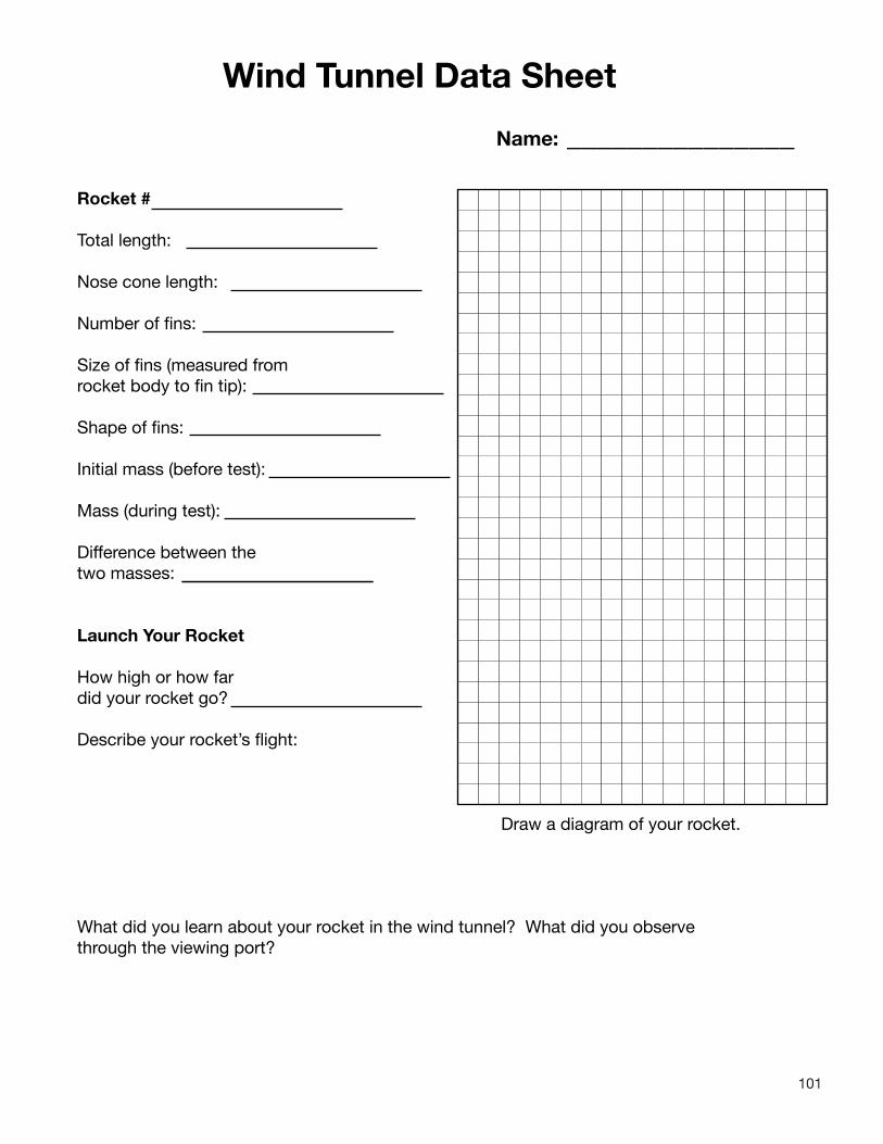
101
Wind Tunnel Data Sheet
Name:
Draw a diagram of your rocket.
_______________
Rocket #
Total length:
Nose cone length:
Number of fins:
Size of fins (measured from rocket body to fin tip):
Shape of fins:
Initial mass (before test):
Mass (during test):
Difference between thetwo masses:
Launch Your Rocket
How high or how fardid your rocket go?
Describe your rocket’s flight:
What did you learn about your rocket in the wind tunnel? What did you observe through the viewing port?

102
Wind Tunnel Data Sheet - Final
Name: ______________
Draw a diagram of your rocket.
Rocket #
Total length:
Nose cone length:
Number of fins:
Size of fins (measured from rocket body to fin tip):
Shape of fins:
Initial mass (before test):
Mass (during test):
Difference between thetwo masses:
Launch Your Rocket
How high or how fardid your rocket go?
Describe your rocket’s flight:
What did you do to your rocket to improve its flight performance?
How did your changes affect your rocket in the wind tunnel?
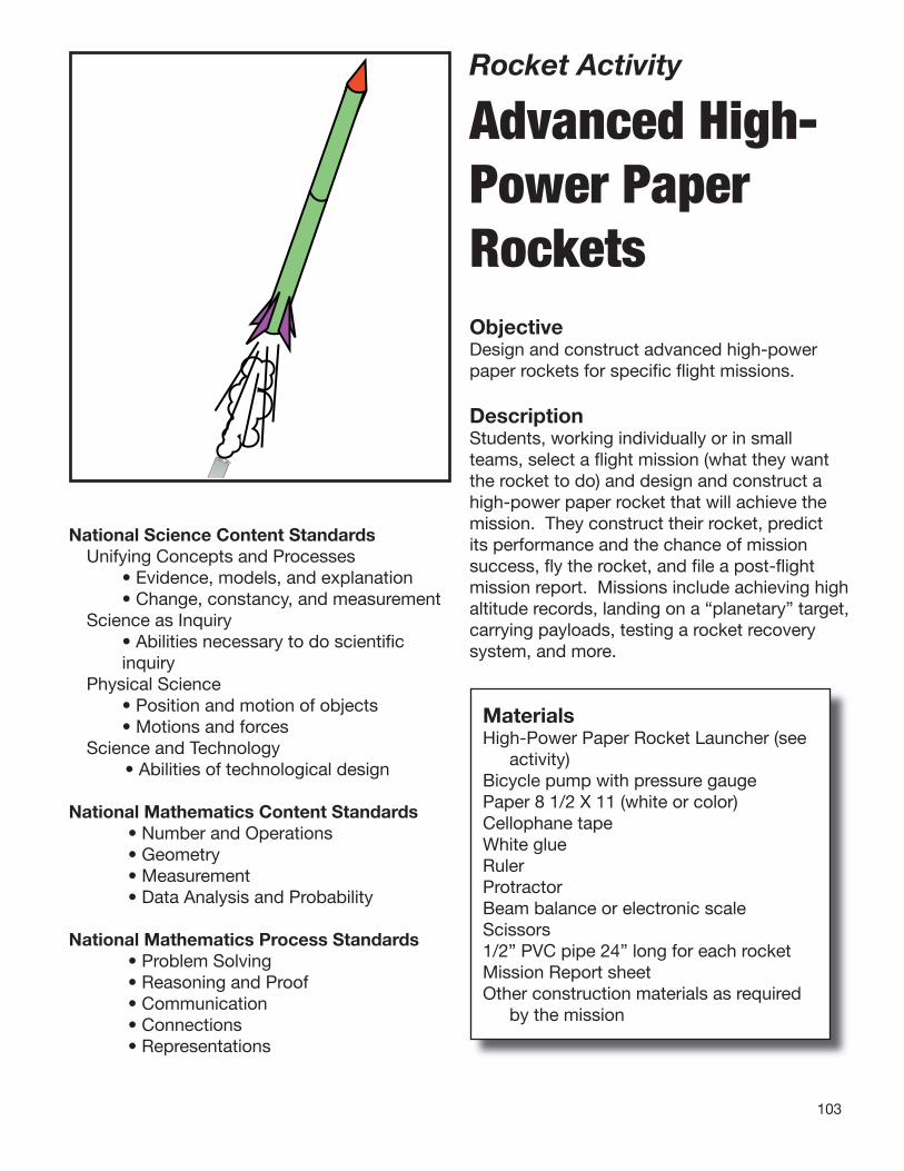
103
Rocket Activity
Advanced High-Power Paper
Rockets ObjectiveDesign and construct advanced high-power paper rockets for specifi c fl ight missions.
DescriptionStudents, working individually or in small teams, select a fl ight mission (what they want the rocket to do) and design and construct a high-power paper rocket that will achieve the mission. They construct their rocket, predict its performance and the chance of mission success, fl y the rocket, and fi le a post-fl ight mission report. Missions include achieving high altitude records, landing on a “planetary” target, carrying payloads, testing a rocket recovery system, and more.
National Science Content StandardsUnifying Concepts and Processes • Evidence, models, and explanation • Change, constancy, and measurementScience as Inquiry • Abilities necessary to do scientifi c
inquiryPhysical Science • Position and motion of objects • Motions and forcesScience and Technology
• Abilities of technological design
National Mathematics Content Standards• Number and Operations• Geometry• Measurement• Data Analysis and Probability
National Mathematics Process Standards• Problem Solving• Reasoning and Proof• Communication• Connections• Representations
MaterialsHigh-Power Paper Rocket Launcher (see
activity)Bicycle pump with pressure gaugePaper 8 1/2 X 11 (white or color)Cellophane tapeWhite glueRulerProtractorBeam balance or electronic scaleScissors1/2” PVC pipe 24” long for each rocketMission Report sheetOther construction materials as required
by the mission

104
ManagementHave students construct and fly a basic paper rocket that will help them to become familiar with rocket design and construction techniques (See the preceding activity.). Discuss possible missions with the students and identify what materials will be needed to fulfill the missions. A day or two before construction begins, have students or teams submit mission proposals. The proposals will identify their mission, what their rocket will look like, how it will function, and what materials they will need for construction. Have the materials ready for the construction days. Demonstrate how to roll and strengthen a double or triple-long paper tube with white glue. Rockets made with glued body tubes will require a couple of days for the several applications of glue to dry. On launch day, post a launch schedule. Organize the schedule so that similar missions are flown consecutively. For example, if the objective is to achieve the greatest altitude, teams will have to arrange for tracking students ready to measure the angle from one or more tracking stations (See the Launch Altitude Tracker activity, page 80). If students have trouble coming up with flight missions, suggest a few possibilities from the list below: Maximum Altitude Precision Landing (basketball planet) Maximum Distance Downrange Carry Payload Parachute Recovery
BackgroundEvery space rocket ever built was constructed with specific missions in mind. The Bumper Project back in the 1950s (See Historical chapter), combined a small WAC Corporal rocket with a V2 to test rocket staging, achieve altitude records, and to carry small payloads for investigating the space environment. The Redstone missile was designed for explosive warheads but later adapted to carrying the first American astronaut into space. The Saturn V was designed to carry astronauts and landing craft to the Moon. It, too, was modified and
used to launch the first U.S. space station, Skylab. The space shuttle, perhaps the most versatile rocket ever designed, was nevertheless a payload and laboratory carrier for low orbit missions. The new Ares I will carry crew to orbit and the Ares V will carry heavy payloads into orbit or to the Moon and beyond.
Procedure Gluing the Body Tube1. Begin rolling the body tube as you would
when making a basic paper rocket with tape. Overlap two or three sheets of paper as you roll. Small bits of tape can be used to secure the papers to each other while rolling. When the paper is partially wrapped around the PVC tube, squeeze a bead of white glue from one end of the paper tube to the other. Spread the glue and continue rolling the tube. Add more glue as you roll. Be careful not to get any glue on the PVC tube.
2. Allow the glue to dry. If any edges of the paper curl up, add some more glue to them and smooth them down.
3. After the tube is dry, smear glue over the entire tube to strengthen it. Several coatings of glue will yield a very strong body tube. (Optional: Mix food coloring into the glue used for the last layer to add color to the rocket.)
4. If a longer body tube is desired, roll two sheets of paper around the PVC tube at the same time and repeat the gluing process.
Procedure Attaching a Payload Carrier1. Roll a rocket body as you would for a basic
rocket. Use a small disk of paper and several pieces of tape to close off the upper end of the body tube.
2. Roll a second piece of paper around the upper end of the body tube and extend it upward the desired amount to make a hollow tube for holding payload. Tape it in place.
3. Insert the payload and close off the upper end with a standard nose cone.
Procedure Making Extra Strong Fins1. Extra strong fins can be made by folding and
gluing multiple layers of paper together. Use
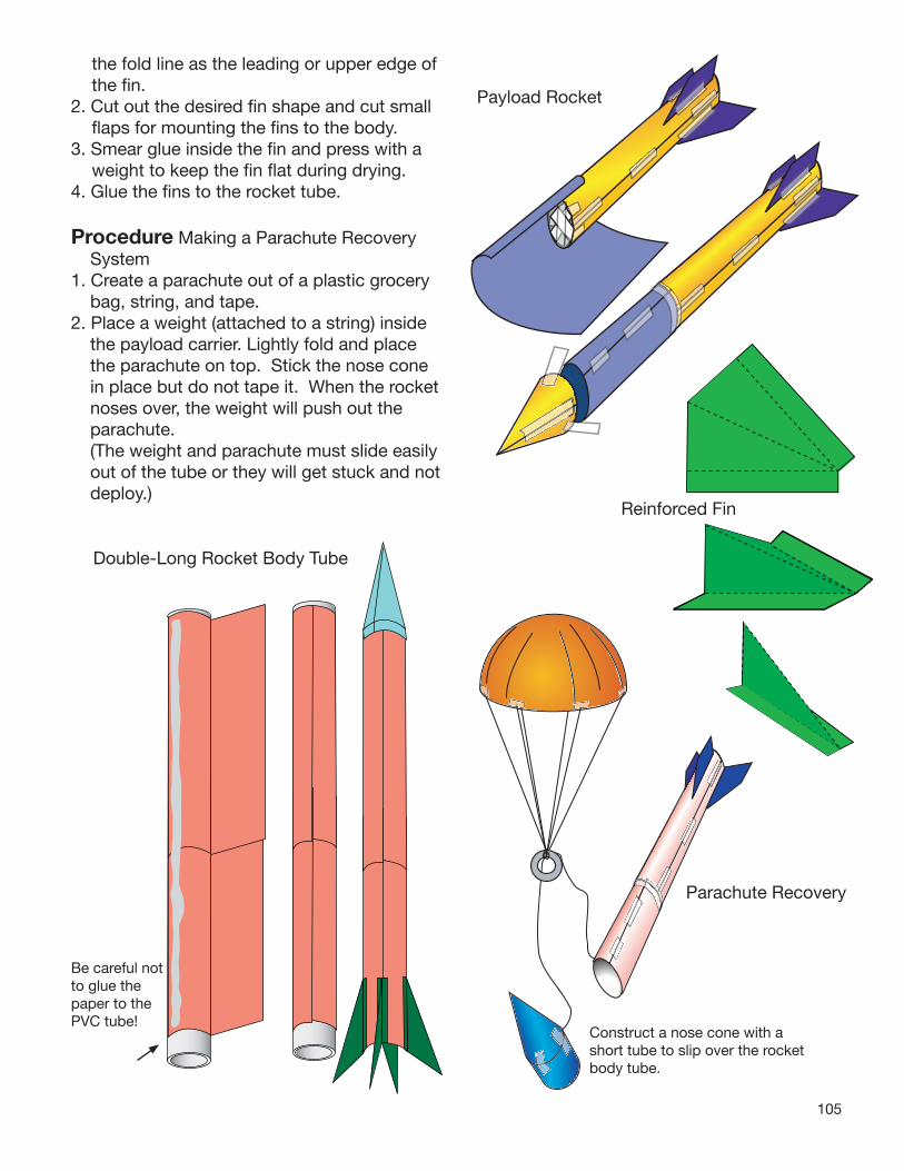
105
Payload Rocket
Parachute Recovery
Construct a nose cone with a short tube to slip over the rocket body tube.
Be careful not to glue the paper to the PVC tube!
the fold line as the leading or upper edge of the fi n.
2. Cut out the desired fi n shape and cut small fl aps for mounting the fi ns to the body.
3. Smear glue inside the fi n and press with a weight to keep the fi n fl at during drying.
4. Glue the fi ns to the rocket tube.
Procedure Making a Parachute Recovery System
1. Create a parachute out of a plastic grocery bag, string, and tape.
2. Place a weight (attached to a string) inside the payload carrier. Lightly fold and place the parachute on top. Stick the nose cone in place but do not tape it. When the rocket noses over, the weight will push out the parachute.
(The weight and parachute must slide easily out of the tube or they will get stuck and not deploy.)
Reinforced Fin
Double-Long Rocket Body Tube
106
Discussion• Why are rockets designed with specific
missions in mind? No one rocket design can meet all the
needs of spaceflight missions. If a small satellite is to be launched it is much simpler, less expensive, and safer to use a small unmanned rocket for the job. If a big payload,such as a module for the International Space Station, is planned, a larger rocket is required and astronauts may be needed to deploy (release) it from the rocket.
• What design feature of the rocket has the greatest effect on flight performance?
Air rockets fly through the air and therefore have to be designed to create as little air resistance as possible. Crooked fins or a blunt nose cone increases air drag (friction), causing the rocket to slow quickly. The second most important design feature is weight. Weight is a more complicated factor than streamlining. Too much weight, and the rocket will not fly very high. The same effect takes place if the rocket weighs too little. Crumple a piece of paper into a ball andand see how far you can throw it. Crumple a second ball of paper around a nickel throw it again. It will go farther. Very lightweight air rockets have a hard time fighting drag as they fly. Very heavy air rockets have a lot of inertia to overcome.
Assessment• Evaluate the mission proposal and postflight
reports for completeness.• Have students write a paper on the role drag
(friction with the air) plays in the performance of a rocket and how drag can be reduced.
• Compare the space shuttle with the new Ares V. Which rocket will have the least amount of drag?
Extensions• Conduct an “X Prize” style competition. The
real X Prize competition led to the first non-government reusable manned spacecraft flights to reach outer space. Use the Internet to learn more about the X Prize Foundation and its current programs. Challenge student teams to create a payload-carrying air rocket that can carry a 100-gram (about 50 small paperclips) payload 50 meters high.

107
Mission ProposalRocket Scientist Names:
What is the name of your rocket?
How long will it be in centimeters?
How many fins will it have?
What special features (if any) will it have?
Describe your mission objective:
How will your rocket achieve its objective?
Provide a detailed list of materials and tools needed to build your rocket (include everything):
1.
2.
3.
4.
5.
6.
7.
8.
9.
10.
Draw a picture of your proposed rocket

108
Post-Flight Report
Rocket Scientist Names:
What was your Mission Objective?
Provide the specifications of your rocket:
Rocket total length in cm:
Fin span (distance from fin tip to fin tip on other side) in cm:
Mass of the rocket in g:
(If your rocket carried a payload)
Mass of payload in g:
Describe its flight:
Was your rocket successful in meeting its objectives?
If not, explain why:
What can you do to improve your rocket’s performance?

109
Rocket Activity
Water Rocket Launcher ObjectiveConstruct a launch platform for launching water rockets.
DescriptionWater rockets, built from plastic soft drink bottles, are capable of fl ights greater than 100 meters. The bottles are partially fi lled with water and pressurized with compressed air delivered by a hand bicycle pump or small compressor. A special launch pad is required for holding the rocket while it is being pressurized. When the desired pressure is reached, the rocket is launched by releasing hold-down clamps. The instructions that follow explain how to construct the launcher and provides a list of needed materials. Only a few tools and simple construction techniques are required to construct a launch pad that can be used year after year.
MaterialsRefer to the shopping list (see page 113)SawDrillScrew driverBicycle pump or small electric compressor
National Science Content StandardsPhysical Science • Position and motion of objects • Motions and forcesScience and Technology
• Abilities of technological design
National Mathematics Content Standards• Measurement
National Mathematics Process Standards• Connections
ManagementMost of the materials on the shopping list are obtained from a hardware/lumber store. If needed, the list can be given to a salesperson to assist in locating the needed parts. The list includes sizes, descriptions, and the number of each part required. A scrap piece of 2x4 may be available at the lumber store. You will need two short
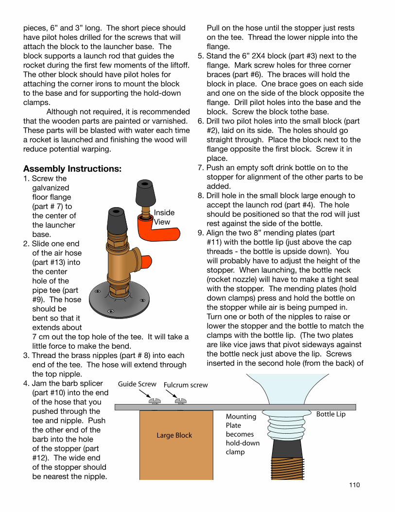
110
pieces, 6” and 3” long. The short piece should have pilot holes drilled for the screws that will attach the block to the launcher base. The block supports a launch rod that guides the rocket during the first few moments of the liftoff. The other block should have pilot holes for attaching the corner irons to mount the block to the base and for supporting the hold-down clamps. Although not required, it is recommended that the wooden parts are painted or varnished. These parts will be blasted with water each time a rocket is launched and finishing the wood will reduce potential warping.
Assembly Instructions:1. Screw the
galvanized floor flange (part # 7) to the center of the launcher base.
2. Slide one end of the air hose (part #13) into the center hole of the pipe tee (part #9). The hose should be bent so that it extends about 7 cm out the top hole of the tee. It will take a little force to make the bend.
3. Thread the brass nipples (part # 8) into each end of the tee. The hothe top nipple.
4. Jam the barb splicer (part #10) into the end of the hose that you pushed through the tee and nipple. Push the other end of the barb into the hole of the stopper (part #12). The wide end of the stopper should be nearest the nipple.
se will extend through
Inside View
Fulcrum screw
Bottle Lip
Large Block
Guide Screw
Mounting Plate becomes hold-downclamp
Pull on the hose until the stopper just rests on the tee. Thread the lower nipple into the flange.
5. Stand the 6” 2X4 block (part #3) next to the flange. Mark screw holes for three corner braces (part #6). The braces will hold the block in place. One brace goes on each side and one on the side of the block opposite the flange. Drill pilot holes into the base and the block. Screw the block tothe base.
6. Drill two pilot holes into the small block (part #2), laid on its side. The holes should go straight through. Place the block next to the flange opposite the first block. Screw it in place.
7. Push an empty soft drink bottle on to the stopper for alignment of the other parts to be added.
8. Drill hole in the small block large enough to accept the launch rod (part #4). The hole should be positioned so that the rod will just rest against the side of the bottle.
9. Align the two 8” mending plates (part #11) with the bottle lip (just above the cap threads - the bottle is upside down). You will probably have to adjust the height of the stopper. When launching, the bottle neck (rocket nozzle) will have to make a tight seal with the stopper. The mending plates (hold down clamps) press and hold the bottle on the stopper while air is being pumped in. Turn one or both of the nipples to raise or lower the stopper and the bottle to match the clamps with the bottle lip. (The two plates are like vice jaws that pivot sideways against the bottle neck just above the lip. Screws inserted in the second hole (from the back) of
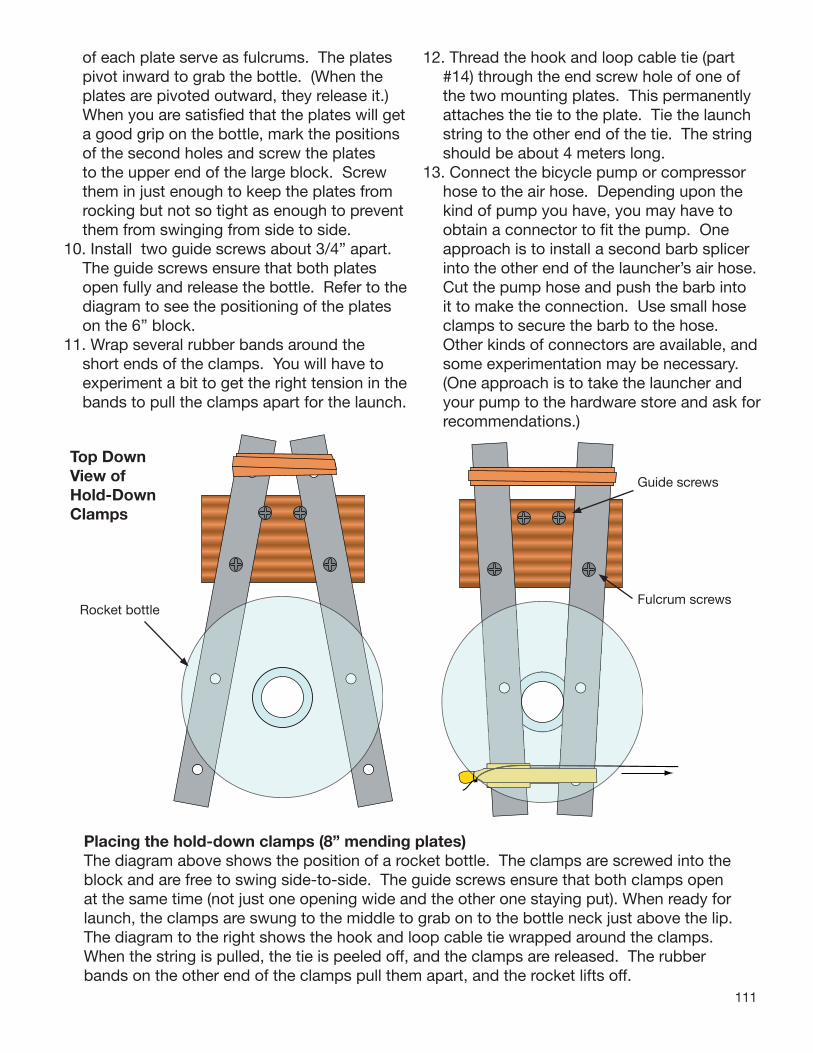
111
of each plate serve as fulcrums. The plates pivot inward to grab the bottle. (When the plates are pivoted outward, they release it.) When you are satisfi ed that the plates will get a good grip on the bottle, mark the positions of the second holes and screw the plates to the upper end of the large block. Screw them in just enough to keep the plates from rocking but not so tight as enough to prevent them from swinging from side to side.
10. Install two guide screws about 3/4” apart. The guide screws ensure that both plates open fully and release the bottle. Refer to the diagram to see the positioning of the plates on the 6” block.
11. Wrap several rubber bands around the short ends of the clamps. You will have to experiment a bit to get the right tension in the bands to pull the clamps apart for the launch.
12. Thread the hook and loop cable tie (part #14) through the end screw hole of one of the two mounting plates. This permanently attaches the tie to the plate. Tie the launch string to the other end of the tie. The string should be about 4 meters long.
13. Connect the bicycle pump or compressor hose to the air hose. Depending upon the kind of pump you have, you may have to obtain a connector to fi t the pump. One approach is to install a second barb splicer into the other end of the launcher’s air hose. Cut the pump hose and push the barb into it to make the connection. Use small hose clamps to secure the barb to the hose. Other kinds of connectors are available, and some experimentation may be necessary. (One approach is to take the launcher and your pump to the hardware store and ask for recommendations.)
Placing the hold-down clamps (8” mending plates)The diagram above shows the position of a rocket bottle. The clamps are screwed into the block and are free to swing side-to-side. The guide screws ensure that both clamps open at the same time (not just one opening wide and the other one staying put). When ready for launch, the clamps are swung to the middle to grab on to the bottle neck just above the lip. The diagram to the right shows the hook and loop cable tie wrapped around the clamps. When the string is pulled, the tie is peeled off, and the clamps are released. The rubber bands on the other end of the clamps pull them apart, and the rocket lifts off.
Top Down View of Hold-Down Clamps
Rocket bottleFulcrum screws
Guide screws

112
15 14
11
6
3
1 2
4
9
12
8
7
13
5
Completed Water Rocket Launcher
10Part not visible
Tips on Using the Launcher• It is important to keep the bottle sealed with
the stopper as it is being pressurized. If the bottle leaks (a small spray comes out as it is being pressurized), the seal is too loose. Raise the stopper by unscrewing one or both of the nipples a turn or two to elevate the stopper.
• New plastic (PET) soft drink bottles are capable of withstanding about 100 or more pounds per square inch (psi) of pressure. A 2 to 1 safety factor is recommended. Do not let students pump the bottle above 50 psi. Bottles can be damaged during the construction process. Also bottles can be damaged on landing. Retire water rockets after 10 flights or sooner if you suspect damage.
• To place a rocket with water inside on the base, hold the rocket horizontally. Tip up the base and push the nozzle onto the stopper. Grasp the bottle with the clamps and hold them in position with the cable wrap. Set the rocket and launch platform level. It is not necessary to anchor the pad on the ground.
• A small pull on the string attached to the cable wrap is enough to peel it back and release the hold-down clamps.
• Students near the launcher should wear safety goggles while the rocket is being pressurized and launched.
• Keep other students about 5 to 10 meters from the launcher (further if you elect to use higher launch pressures).
• Do not let students attempt to catch their rockets unless the rocket has successfully deployed its parachute.

113
1 - Wooden Base(Circle 16” diameter or 16“ square 16”, plywood or joined lumber, 3/4” to 1 1/2” thick) Lumber Supply
Sho
pp
ing
Lis
t
1
2
1 - 1/4” I.D. Barb Splicer(brass)
Drill pilot screw holes and hole for the dowel launch rod
1 - 1/2” Galv FLR Flangewith screwsHardware store
1 - Number 3, 1 hole Rubber StopperSchool science supply, Some hardware stores
2 - 8” Mending Platewith screwsHardware store
2 - 1/2 MIP Hex Nipple (brass)Hardware store
1 - 1/2” Cast Female Pipe Tee (brass)Hardware store
1 - 3” Wood Block (cut from 2X4)Lumber Supply
1 - 6” Wood Block(cut from 2X4)Lumber Supply
6-10’ - 1/2” O.D. 1/4” I.D. High Pressure Air Hose(with connector for bicycle pump/compressor)Hardware Store
1 - 5/16” Dowel (36” long)Lumber Supply
3 - 1 1/2” x 5/8” Corner BraceHardware store
4 - #12 pan head metalscrews4 - #10x3/4” wood screws2 - #10x2 1/2” wood screwsHardware store
3
4
5
6
7
8
9
10
11
12
13
14
15
Hook and Loop Cable Tie(e.g., Velcro® One Wrap)Office or Hardware store
#64 Rubber BandsOffice store
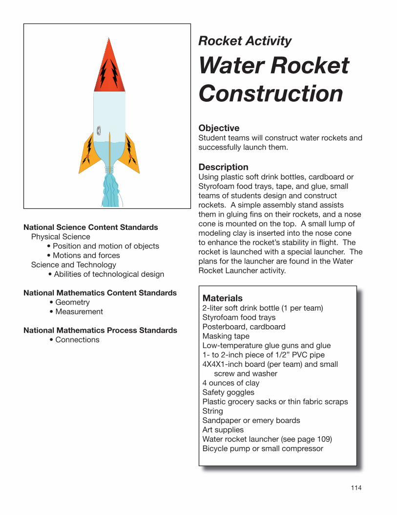
114
Rocket Activity
Water Rocket
Construction ObjectiveStudent teams will construct water rockets and successfully launch them.
DescriptionUsing plastic soft drink bottles, cardboard or Styrofoam food trays, tape, and glue, small teams of students design and construct rockets. A simple assembly stand assists them in gluing fi ns on their rockets, and a nose cone is mounted on the top. A small lump of modeling clay is inserted into the nose cone to enhance the rocket’s stability in fl ight. The rocket is launched with a special launcher. The plans for the launcher are found in the Water Rocket Launcher activity.
National Science Content StandardsPhysical Science • Position and motion of objects • Motions and forcesScience and Technology
• Abilities of technological design
National Mathematics Content Standards• Geometry• Measurement
National Mathematics Process Standards• Connections
Materials2-liter soft drink bottle (1 per team)Styrofoam food traysPosterboard, cardboardMasking tapeLow-temperature glue guns and glue1- to 2-inch piece of 1/2” PVC pipe4X4X1-inch board (per team) and small
screw and washer4 ounces of clay Safety gogglesPlastic grocery sacks or thin fabric scraps StringSandpaper or emery boardsArt suppliesWater rocket launcher (see page 109)Bicycle pump or small compressor

115
ManagementBegin collecting 2-liter soft drink bottles a few weeks before the activity. Save the caps, too. Rinse the bottles and remove the labels. There will be some glue adhesive remaining on the bottle. Goo remover can be used to clean it off, but it tends to smear the surface. Construct assembly stands out of small blocks of wood. Attach a bottle cap to the middle of each board with a small screw and a washer through the cap. When students begin constructing their rockets, they screw the bottle neck into the cap, and the board below will hold the rocket upright for gluing. The blocks also make a convenient way of storing the rockets upright when not being worked on.
Launch lug with slanted cuts.
Make mounting stands by screwing the plastic bottle caps to a board. Use a washer for added strength.
Pre-cut the PVC segments. The cuts canbe slanted to streamline them. A saw or PVC cutter is used for cutting. The segments act as launch lugs to guide the rocket up the launch rod during the first moments of skyward climb. Be sure to use low-temperature glue guns. High-temperature guns will melt the plastic bottle. A small dish of ice water in a central location is helpful for students who get hot glue on their fingers. Immersing the fingers will immediately chill the
the rocket’s
glue. Do not put bowls of water near the guns themselves because the guns use electricity for heating, and shorting could occur if they get wet.
Special Note The activity entitled Project X-51 (see page 118) lays out an entire process
for constructing water rockets through launch and reporting. Student teams form rocket companies and compete for government contracts. The procedures that follow here should be used for the construction phase of Project X-51.
BackgroundA water rocket is a chamber, usually a 2-liter soft drink bottle, partially filled with water. Air is forced inside with a pump. When the rocket is released, the pressurized air forces water out the nozzle (pour spout). The bottle launches itself in the opposite direction. The bottle usually has a nose cone for streamlining and fins for stability. Water rockets are easily capable of 100-meter-high flights, but advanced hobbyists have combined bottles and staged bottles for flights over 300 meters high. Water bottle rockets are ideal for teaching Newton’s laws of motion. The launch of the rocket easily demonstrates Newton’s third law. Students can see the water shooting out of the nozzle (action) and see the rocket streak into the sky (reaction). Students can also experiment with different pressure levels inside the chamber and different amounts of water. The rocket will not fly very high if it is filled only with air. The air will quickly rush out during the launch, but its mass is very low. Consequently, the thrust produced is also low (Newton’s second law). By placing water in the bottle, the air has to force the water out first before it can leave the bottle. The water increases the mass expelled by the rocket, thereby increasing the thrust. Like all rockets, the flight performance of water bottle rockets is strongly influenced by the rocket’s design and the care taken in its construction. Beveling the leading and trailing edges of fins allows them to slice through the air more cleanly. Straight-mounted fins produce little friction or drag with the air. A small amount of ballast weight inside the nose cone helps balance the rocket. This moves the center of mass of the rocket forward while still leaving a large fin surface area at the rear. In flight, the

116
rocket design acts like a weather vane, with the nose cone pointed up and the fi ns down.
Procedure1. Set up a supply station with materials such
as Styrofoam food trays, posterboard, tape, sandpaper, and art supplies.
2. Set up a gluing station with several heated low-temperature glue guns and extra glue sticks.
3. Divide students into teams for constructing rockets. If using Project X-51, describe the project to them and explain its objectives. Discuss construction techniques for their rockets. Give each team an assembly stand and a 2-liter soft drink bottle. Project X-51 requires teams to keep track of the materials they used. Even if they are not doing the project, it is still good for teams to account for the materials used.
4. Show teams how to use the glue guns and point out the cold water dish in case glue gets on fi ngers. Students should wear safety goggles when gluing.
5. Describe how fi ns can be smoothed with sandpaper to slice through the air with little drag.
6. Remind teams to add clay to the inside of their nose cones.
Trim fi n edges with sandpaper to give them knife-blade shapes to slice through the air.
The Assembly Stand supports the rocket while it is being constructed.
7. Have teams glue launch lugs to the side of the rocket midway up the body of the rocket and position it midway between two fi ns.
8. Challenge teams to think up a way to add a parachute to their rockets for soft landings. Plastic grocery bags or lightweight fabric scraps can be cut to make parachutes and strings can be used to attach them. The nose cone must remain in place until the rocket reaches the top of its fl ight; then it should open and release the parachute.
Launch Lug
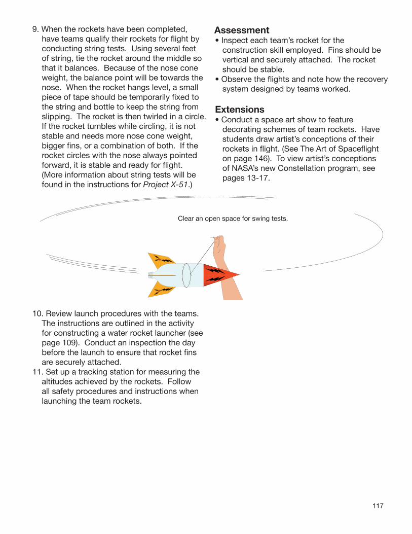
117
9. When the rockets have been completed, have teams qualify their rockets for fl ight by conducting string tests. Using several feet of string, tie the rocket around the middle so that it balances. Because of the nose cone weight, the balance point will be towards the nose. When the rocket hangs level, a small piece of tape should be temporarily fi xed to the string and bottle to keep the string from slipping. The rocket is then twirled in a circle. If the rocket tumbles while circling, it is not stable and needs more nose cone weight, bigger fi ns, or a combination of both. If the rocket circles with the nose always pointed forward, it is stable and ready for fl ight. (More information about string tests will be found in the instructions for Project X-51.)
10. Review launch procedures with the teams. The instructions are outlined in the activity for constructing a water rocket launcher (see page 109). Conduct an inspection the day before the launch to ensure that rocket fi ns are securely attached.
11. Set up a tracking station for measuring the altitudes achieved by the rockets. Follow all safety procedures and instructions when launching the team rockets.
Clear an open space for swing tests.
Assessment• Inspect each team’s rocket for the
construction skill employed. Fins should be vertical and securely attached. The rocket should be stable.
• Observe the fl ights and note how the recovery system designed by teams worked.
Extensions • Conduct a space art show to feature
decorating schemes of team rockets. Have students draw artist’s conceptions of their rockets in fl ight. (See The Art of Spacefl ight on page 146). To view artist’s conceptions of NASA’s new Constellation program, see pages 13-17.
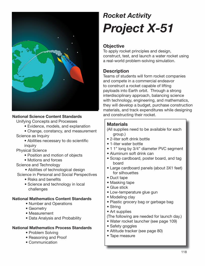
118
Rocket Activity
Project X-51 ObjectiveTo apply rocket principles and design, construct, test, and launch a water rocket using a real-world problem-solving simulation.
DescriptionTeams of students will form rocket companies and compete in a commercial endeavor to construct a rocket capable of lifting payloads into Earth orbit. Through a strong interdisciplinary approach, balancing science with technology, engineering, and mathematics, they will develop a budget, purchase construction materials, and track expenditures while designing and constructing their rocket.
Project X-51
National Science Content StandardsUnifying Concepts and Processes • Evidence, models, and explanation • Change, constancy, and measurementScience as Inquiry • Abilities necessary to do scientifi c
inquiryPhysical Science • Position and motion of objects • Motions and forcesScience and Technology
• Abilities of technological design Science in Personal and Social Perspectives
• Risks and benefi ts • Science and technology in local
challenges
National Mathematics Content Standards• Number and Operations• Geometry• Measurement• Data Analysis and Probability
National Mathematics Process Standards• Problem Solving• Reasoning and Proof• Communication
Materials(All supplies need to be available for each
group.)• 2-liter soft drink bottle• 1-liter water bottle• 1 1” long by 3/4” diameter PVC segment• Aluminum soft drink can• Scrap cardboard, poster board, and tag
board• Large cardboard panels (about 3X1 feet)
for silhouettes• Duct tape• Masking tape• Glue stick• Low-temperature glue gun• Modeling clay• Plastic grocery bag or garbage bag• String• Art supplies(The following are needed for launch day.)• Water rocket launcher (see page 109)• Safety goggles• Altitude tracker (see page 80)• Tape measure
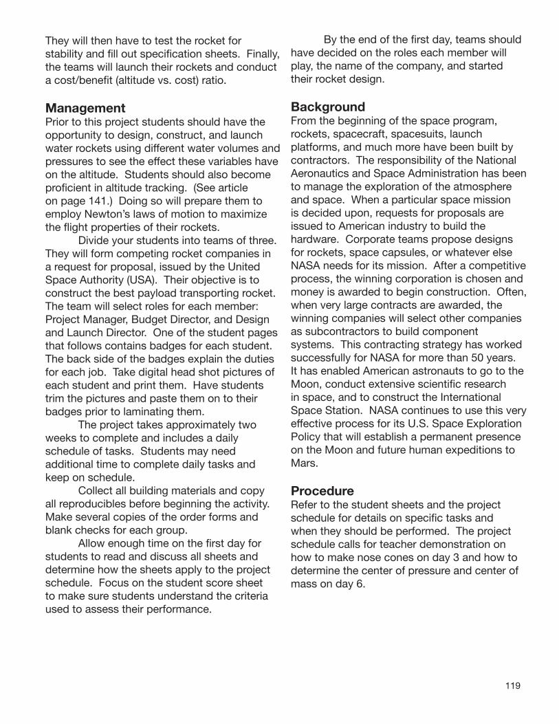
119
They will then have to test the rocket for stability and fill out specification sheets. Finally, the teams will launch their rockets and conduct a cost/benefit (altitude vs. cost) ratio.
ManagementPrior to this project students should have the opportunity to design, construct, and launch water rockets using different water volumes and pressures to see the effect these variables have on the altitude. Students should also become proficient in altitude tracking. (See article on page 141.) Doing so will prepare them to employ Newton’s laws of motion to maximize the flight properties of their rockets. Divide your students into teams of three. They will form competing rocket companies in a request for proposal, issued by the United Space Authority (USA). Their objective is to construct the best payload transporting rocket. The team will select roles for each member: Project Manager, Budget Director, and Design and Launch Director. One of the student pages that follows contains badges for each student. The back side of the badges explain the duties for each job. Take digital head shot pictures of each student and print them. Have students trim the pictures and paste them on to their badges prior to laminating them. The project takes approximately two weeks to complete and includes a daily schedule of tasks. Students may need additional time to complete daily tasks and keep on schedule. Collect all building materials and copy all reproducibles before beginning the activity. Make several copies of the order forms and blank checks for each group. Allow enough time on the first day for students to read and discuss all sheets and determine how the sheets apply to the project schedule. Focus on the student score sheet to make sure students understand the criteria used to assess their performance.
By the end of the first day, teams should have decided on the roles each member will play, the name of the company, and started their rocket design.
BackgroundFrom the beginning of the space program, rockets, spacecraft, spacesuits, launch platforms, and much more have been built by contractors. The responsibility of the National Aeronautics and Space Administration has been to manage the exploration of the atmosphere and space. When a particular space mission is decided upon, requests for proposals are issued to American industry to build the hardware. Corporate teams propose designs for rockets, space capsules, or whatever else NASA needs for its mission. After a competitive process, the winning corporation is chosen and money is awarded to begin construction. Often, when very large contracts are awarded, the winning companies will select other companies as subcontractors to build component systems. This contracting strategy has worked successfully for NASA for more than 50 years. It has enabled American astronauts to go to the Moon, conduct extensive scientific research in space, and to construct the International Space Station. NASA continues to use this very effective process for its U.S. Space Exploration Policy that will establish a permanent presence on the Moon and future human expeditions to Mars.
ProcedureRefer to the student sheets and the project schedule for details on specific tasks and when they should be performed. The project schedule calls for teacher demonstration on how to make nose cones on day 3 and how to determine the center of pressure and center of mass on day 6.

120
Discussion• What did you learn about running a company?
How might you have done things differently? What was the most difficult part of the two weeks? What do you understand now that you were not sure or aware of before?
AssessmentBase the assessment of team performance on their documentation: Project Journal, Silhouette, and Launch Results. Refer to the Project X-51 Score Sheet for details.
Extensions• Large space missions often require a wide
range of subcontractors across the United States to provide the expertise needed to build the launch and vehicle systems. Learn about the contributions contractors in your state make towards the exploration of outer space. A good place to start is with the Space Grant Consortium for your state. Consortium members (colleges and universities) promote space research and educational activities in their home states and work with local space industries. The following website contains a listing of Space Grant colleges by state:
http://www.nasa.gov/audience/foreducators/postsecondary/grants/Space_Grant.html.
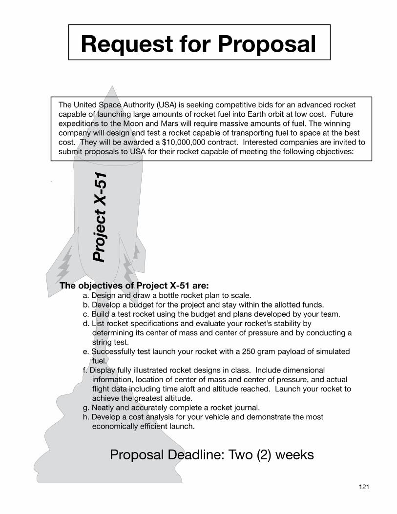
121
Request for Proposal
The United Space Authority (USA) is seeking competitive bids for an advanced rocket capable of launching large amounts of rocket fuel into Earth orbit at low cost. Future expeditions to the Moon and Mars will require massive amounts of fuel. The winning company will design and test a rocket capable of transporting fuel to space at the best cost. They will be awarded a $10,000,000 contract. Interested companies are invited to submit proposals to USA for their rocket capable of meeting the following objectives:
Pro
ject
X-5
1
The objectives of Project X-51 are:a. Design and draw a bottle rocket plan to scale.b. Develop a budget for the project and stay within the allotted funds.
c. Build a test rocket using the budget and plans developed by your team. d. List rocket specifications and evaluate your rocket’s stability by
determining its center of mass and center of pressure and by conducting a string test.
e. Successfully test launch your rocket with a 250 gram payload of simulated fuel.
f. Display fully illustrated rocket designs in class. Include dimensional information, location of center of mass and center of pressure, and actual flight data including time aloft and altitude reached. Launch your rocket to achieve the greatest altitude.
g. Neatly and accurately complete a rocket journal. h. Develop a cost analysis for your vehicle and demonstrate the most
economically efficient launch.
Proposal Deadline: Two (2) weeks

122
Project Schedule
Project X-51 Schedule
Day 1• Form rocket companies.• Pick company officers.• Brainstorm ideas for design and budget.• Sketch preliminary rocket design.
Project X-51 Schedule
Day 2• Develop materials and • budget list.• Develop scale drawing.
Project X-51 Schedule
Day 3• Demonstration: nose cone construction.• Issue materials and begin construction.
Project X-51 Schedule
Day 4• Continue construction.
Project X-51 Schedule
Day 5• Continue construction.
Project X-51 Schedule
Day 6• Demonstration: Find center of mass and center of pressure.• Introduce rocket silhouette construction and begin rocket analysis.
Project X-51 Schedule
Day 7• Finish silhouette construction and complete prelaunch analysis. Hang silhouette.• Perform swing test.
Project X-51 Schedule
Day 8• Launch Day!
Project X-51 Schedule
Day 9• Complete post launch results, silhouette documentation.• Prepare journal for collection.• Documentation and journal due at beginning of class tomorrow.

123
Project X-51 Checklist
Project Grading:
50% Documentation - See Project Journal below. Must be complete and neat. 25% Proper display and documentation of rocket silhouette. 25% Launch data - Measurements, accuracy, and completeness.
Project Awards:USA will award exploration contracts to the companies with the top three rocket designs based on the above criteria. The awards are valued at: First $10,000,000 Second $ 5,000,000 Third $ 3,000,000
Project Journal: Check off items as you complete them.
1. Creative cover with members’ names, date, project number and company name.
2. Certificate of Assumed Name (registration of the name of your business).
3. Scale drawing of rocket plans. Clearly indicate scale. Label: Top, Side, and End views.
4. Budget Projection.
5. Balance Sheet.
6. Canceled checks. Staple checks on a page in ascending numerical order (3 to a page).
7. Pre-Launch Analysis
8. Rocket Launch Day Log.
9. Score Sheet (part 3).

124
X-5
1C
ut O
utBadges
Each team member will be assigned specific tasks to help their team function successfully. All team members assist with design, construction, launch, and paperwork. Print the badges and fold them on the dashed lines. Take digital pictures of the teams and paste head shot prints inside the boxes on the front of the badges. Laminate the badges and provide string loops or clips for wearing them.
Des
ign
and
La
unch
Dir
ecto
r
Supervises design and construction of rocket. D
irects others during launch.• Subm
it neat copy of the rocket scale draw
ing.• C
onduct String Test.• R
ecord and submit neat copy of
the Launch Day Log.
• Arrange for creative report cover.• C
omplete silhouette inform
ation and display properly in room
.• Assist other team
mem
bers as needed.
Oversees the project. Keeps
others on task. Only person w
ho can com
municate w
ith the teacher.• M
ake a neat copy of the team’s
Rocket Journal.
• Use appropriate labels as
necessary.• C
heck balance sheet and list of all m
aterials used in rocket construction.
• Co-sign all checks.
• Assist other team m
embers as
needed.
X-5
1
Bud
get
Dir
ecto
r
Cut
Out
X-5
1
Pro
ject
Man
ager
Cut
Out
Keeps accurate account of money
and expenses and pays bills.M
ust sign all checks.• Arrange all canceled checks in
ascending numerical order and
staple three to a sheet of paper. • C
heck over budget projection sheet. Be sure to show
total project cost estim
ates.• C
heck over balance sheet. Be sure colum
ns are complete and
indicate a positive or negative balance.
• Co-sign all checks.
• Com
plete part 3 of the score sheet.
• Assist other team m
embers as
needed.

125
State of:
Certificateof
Assumed Name
Filing Date: , 20
Project Number:
State the exact assumed name under which the business will be be conducted:
List the name of the officers of the business:
Project Manager
Budget Director
Design and Launch Director
Describe the product of your business:
A filing fee of $50.00 must accompany this form.Make out the check to “Registrar.”
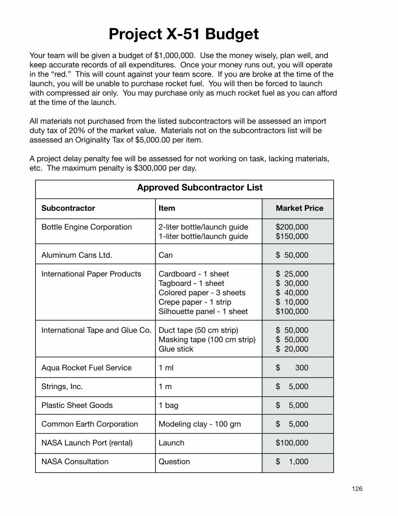
126
Project X-51 BudgetYour team will be given a budget of $1,000,000. Use the money wisely, plan well, and keep accurate records of all expenditures. Once your money runs out, you will operate in the “red.” This will count against your team score. If you are broke at the time of the launch, you will be unable to purchase rocket fuel. You will then be forced to launch with compressed air only. You may purchase only as much rocket fuel as you can afford at the time of the launch.
All materials not purchased from the listed subcontractors will be assessed an import duty tax of 20% of the market value. Materials not on the subcontractors list will be assessed an Originality Tax of $5,000.00 per item.
A project delay penalty fee will be assessed for not working on task, lacking materials, etc. The maximum penalty is $300,000 per day.
Approved Subcontractor List
Subcontractor Item Market Price
Bottle Engine Corporation 2-liter bottle/launch guide $200,000 1-liter bottle/launch guide $150,000
Aluminum Cans Ltd. Can $ 50,000
International Paper Products Cardboard - 1 sheet $ 25,000 Tagboard - 1 sheet $ 30,000 Colored paper - 3 sheets $ 40,000 Crepe paper - 1 strip $ 10,000 Silhouette panel - 1 sheet $100,000
International Tape and Glue Co. Duct tape (50 cm strip) $ 50,000 Masking tape (100 cm strip) $ 50,000 Glue stick $ 20,000
Aqua Rocket Fuel Service 1 ml $ 300
Strings, Inc. 1 m $ 5,000
Plastic Sheet Goods 1 bag $ 5,000
Common Earth Corporation Modeling clay - 100 gm $ 5,000
NASA Launch Port (rental) Launch $100,000
NASA Consultation Question $ 1,000

127
Project X-51 Purchase Order FormCheck No. Date: , 20
Budget Director’s Signature:
Supply Company Name:
Items Ordered: Quantity Unit Price Cost
.
.
.
Company Name:
.
.
P.O. No:
Total
Project X-51 Purchase Order FormCheck No. Date: , 20
Budget Director’s Signature:
Supply Company Name:
Items Ordered: Quantity Unit Price Cost
Company Name:
.
.
.
.
.
P.O. No:
Total
Project X-51 Purchase Order FormCheck No. Date: , 20
Budget Director’s Signature:
Supply Company Name:
Items Ordered: Quantity Unit Price Cost
Company Name:
.
.
.
.
.
P.O. No:
Total
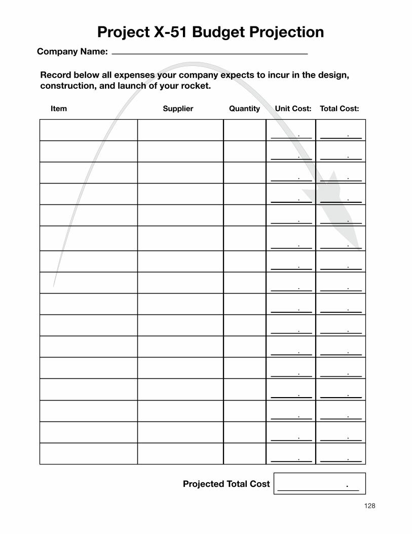
128
. .
. .
. .
. .
. .
Project X-51 Budget ProjectionCompany Name:
Record below all expenses your company expects to incur in the design,construction, and launch of your rocket.
. .
. .
. .
. .
. .
. .
. .
. .
. .
. .
. .
Item Supplier Quantity Unit Cost: Total Cost:
Projected Total Cost .

129
Check No.CompanyName:
Pay to theOrder of: $
Dollars
NationalSpaceBank
For:
Project ManagerSignature:
Budget DirectorSignature:
30109932 0295110 175
Date: , 20
Keep this stub for your records
Check No:
Date: , 20
To:
For:
Amount:$
Check No.CompanyName:
Pay to theOrder of: $
Dollars
NationalSpaceBank
For:
Project ManagerSignature:
Budget DirectorSignature:
30109932 0295110 175
Date: , 20
Keep this stub for your records
Check No:
Date: , 20
To:
For:
Amount:$
Check No.CompanyName:
Pay to theOrder of: $
Dollars
NationalSpaceBank
For:
Project ManagerSignature:
Budget DirectorSignature:
30109932 0295110 175
Date: , 20
Keep this stub for your records
Check No:
Date: , 20
To:
For:
Amount:$

130
. .
. .
. .
. .
. .
. .
. .
. .
. .
. .
. .
. .
. .
. .
. .
. .
. .
. .
. .
. .
. .
. .
Company Name:
Check No. Date: To: Amount: Balance:
Project X-51 Balance Sheet
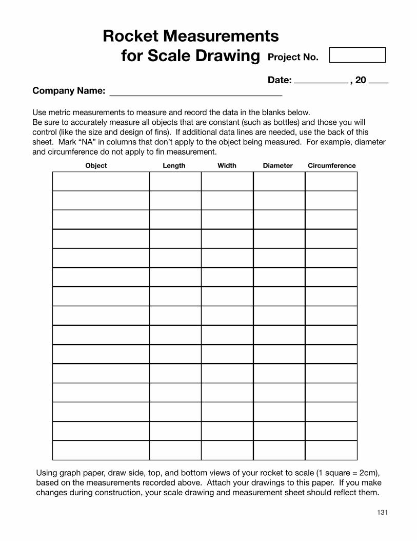
131
Rocket Measurementsfor Scale Drawing Project No.
Date: , 20Company Name:
Use metric measurements to measure and record the data in the blanks below.Be sure to accurately measure all objects that are constant (such as bottles) and those you will control (like the size and design of fins). If additional data lines are needed, use the back of this sheet. Mark “NA” in columns that don’t apply to the object being measured. For example, diameter and circumference do not apply to fin measurement.
Object Length Width Diameter Circumference
Using graph paper, draw side, top, and bottom views of your rocket to scale (1 square = 2cm), based on the measurements recorded above. Attach your drawings to this paper. If you make changes during construction, your scale drawing and measurement sheet should reflect them.

132
Sca
le: 1
sq
uare
= 2
cen
tim
eter
sCompany Name:
Pro
ject
X-5
1 S
cale
Dra
win
g
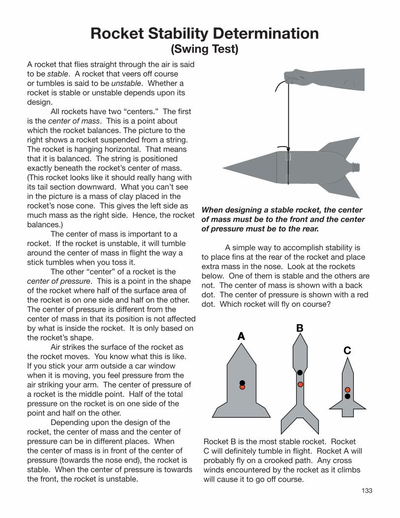
133
Rocket Stability Determination(Swing Test)
A rocket that fl ies straight through the air is saidto be stable. A rocket that veers off course or tumbles is said to be unstable. Whether a rocket is stable or unstable depends upon its design. All rockets have two “centers.” The fi rst is the center of mass. This is a point about which the rocket balances. The picture to the right shows a rocket suspended from a string. The rocket is hanging horizontal. That means that it is balanced. The string is positioned exactly beneath the rocket’s center of mass. (This rocket looks like it should really hang with its tail section downward. What you can’t see in the picture is a mass of clay placed in the rocket’s nose cone. This gives the left side as much mass as the right side. Hence, the rocketbalances.) The center of mass is important to a rocket. If the rocket is unstable, it will tumble around the center of mass in fl ight the way a stick tumbles when you toss it. The other “center” of a rocket is the center of pressure. This is a point in the shape of the rocket where half of the surface area of the rocket is on one side and half on the other. The center of pressure is different from the center of mass in that its position is not affectedby what is inside the rocket. It is only based on the rocket’s shape. Air strikes the surface of the rocket as the rocket moves. You know what this is like. If you stick your arm outside a car window when it is moving, you feel pressure from the air striking your arm. The center of pressure of a rocket is the middle point. Half of the total pressure on the rocket is on one side of the point and half on the other. Depending upon the design of the rocket, the center of mass and the center of pressure can be in different places. When the center of mass is in front of the center of pressure (towards the nose end), the rocket is stable. When the center of pressure is towards the front, the rocket is unstable.
When designing a stable rocket, the center of mass must be to the front and the center of pressure must be to the rear.
A simple way to accomplish stability is to place fi ns at the rear of the rocket and place extra mass in the nose. Look at the rockets below. One of them is stable and the others are not. The center of mass is shown with a back dot. The center of pressure is shown with a red dot. Which rocket will fl y on course?
AAAB
C
Rocket B is the most stable rocket. Rocket C will defi nitely tumble in fl ight. Rocket A will probably fl y on a crooked path. Any cross winds encountered by the rocket as it climbs will cause it to go off course.

134
How to Determine Your Rocket’s Stability1. Draw a scale diagram of your rocket on the
graph paper. Make it exactly to the shape of your rocket as seen from the side.
2. Tie a string loop snugly around your rocket so that you have one long end to hold. Except for the water needed for launch, your rocket should be set up exactly as it will be during launch.
2. Slide the loop until the rocket hangs horizontally. When it hangs horizontally, the string is at the rocket’s center of mass. Mark that spot in the middle of your rocket on the scale diagram. Use a black dot.
3. Cut out a silhouette of your rocket from a piece of cardboard. Make it exactly the same shape and size of your rocket as seen from the side.
4. Balance the silhouette on the edge of a ruler. The center of pressure of your rocket is where the ruler is located. Mark that spot in the middle of your rocket on the scale diagram. Use a red dot.
5. If the center of pressure is before (towards the rocket’s nose) the center of mass, add some additional clay to the rocket OR increase the size of the fins. Repeat the tests until the center of mass is in front.
6. Verify your design results by conducting a swing test. Balance the rocket again with the string. Use a couple of pieces of masking tape to hold the string loop in position.
7. Stand in a clear area and slowly start the rocket swinging in a circle. If the rocket is really stable, it will swing with its nose forward and the tail to the back.
Center of Pressure
Center of Mass
Center of Pressure
Scale Diagram
Swing Test
Center of Pressure
Center of Mass
Center of Pressure
Scale Diagram
In flight, the rocket will try to tumble around its center of mass. If the center of pressure is properly placed, the rocket will fly straight instead. More air pressure will be exerted on the lower end of the rocket than the upper end. This keeps the lower end down and the nose pointed up!
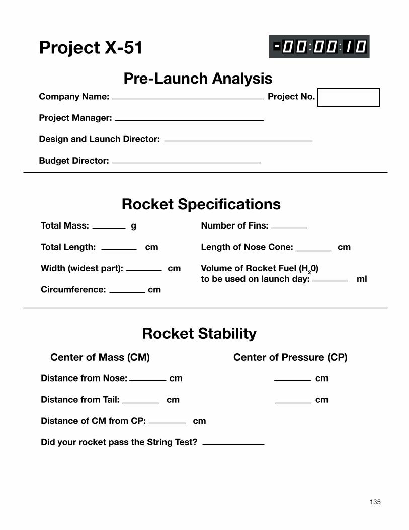
135
Project X-51
Pre-Launch AnalysisCompany Name: Project No.
Project Manager:
Design and Launch Director:
Budget Director:
Rocket SpecificationsTotal Mass: g Number of Fins:
Total Length: cm Length of Nose Cone: cm
Width (widest part): cm Volume of Rocket Fuel (H20) to be used on launch day: mlCircumference: cm
Rocket StabilityCenter of Mass (CM) Center of Pressure (CP)
Distance from Nose: cm cm
Distance from Tail: cm cm
Distance of CM from CP: cm
Did your rocket pass the String Test?

136
Flight Day Log Date: , 20 Project No. Time:
Company Name:
Launch Director:
Weather Conditions:
Wind Speed: mph Wind Direction:
Air Temperature: oC
Launch Location:
Launch Angle (degrees): Launch Direction:
Fuel (Water) Volume: ml Pressure: psi
Altitude Reached: m
Evaluate your rocket’s performance:
Recommendations for future flights:

137
Project X-51 Score Sheet
Total Score: Project No.
Date: , 20
Company Name
Part 1: Documentation = 50% of project grade
Neatness Completeness
Accuracy Order
On Time Score:
Part II: Silhouette = 25% of project grade
Neatness Completeness
Accuracy Proper balance
Correct use of labels Score:
Part III: Launch Results = 25% of project grade (teams complete this section)
a. Rocket Altitude Rank
b. Expenditures and Penalty Fees (Check total from Balance Sheet)
c. Final Balance (New Balance on Balance Sheet)
d. Efficiency (Cost/meter) (Divide investment (b) by Rocket Altitude (a)
e. Contract Award
f. Profit (Contract Award (e) minus Expenditures (b) Score:

138
DIS
CO
VER
Y
U N I T E D S T A T E S
AC
HIE
VE
ME
NT
AW
AR
D
Be it know
n that
d
UUU SS AAA
has mastered the Science, T
echnology, Engineering, an
Mathematics of rocketry and is now
a
RO
CK
ET
SC
IEN
TIS
T
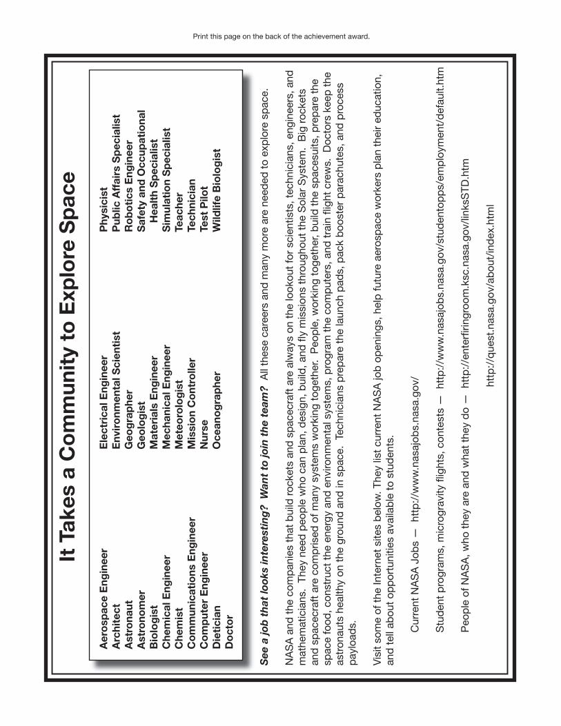
139
It T
akes
a C
om
mun
ity
to E
xplo
re S
pac
e
Aer
osp
ace
Eng
inee
r A
rchi
tect
Ast
rona
utA
stro
nom
erB
iolo
gis
tC
hem
ical
Eng
inee
r C
hem
ist
Co
mm
unic
atio
ns E
ngin
eer
Co
mp
uter
Eng
inee
r D
ieti
cian
Do
cto
r
Ele
ctri
cal E
ngin
eer
Env
iro
nmen
tal S
cien
tist
G
eog
rap
her
Geo
log
ist
Mat
eria
ls E
ngin
eer
Mec
hani
cal E
ngin
eer
Met
eoro
log
ist
Mis
sio
n C
ont
rolle
rN
urse
Oce
ano
gra
phe
r
Phy
sici
st
Pub
lic A
ffai
rs S
pec
ialis
tR
ob
oti
cs E
ngin
eer
Saf
ety
and
Occ
upat
iona
l
Hea
lth
Sp
ecia
list
Sim
ulat
ion
Sp
ecia
list
Teac
her
Tech
nici
an
Test
Pilo
tW
ildlif
e B
iolo
gis
t
See
a jo
b t
hat
look
s in
tere
stin
g?
Wan
t to
join
th
e te
am?
All
thes
e ca
reer
s an
d m
any
mor
e ar
e ne
eded
to
exp
lore
sp
ace.
NA
SA
and
the
com
pan
ies
that
bui
ld r
ocke
ts a
nd s
pac
ecra
ft a
re a
lway
s on
the
look
out
for
scie
ntis
ts, t
echn
icia
ns, e
ngin
eers
, and
mat
hem
atic
ians
. Th
ey n
eed
peo
ple
who
can
pla
n, d
esig
n, b
uild
, and
fl y
mis
sion
s th
roug
hout
the
Sol
ar S
yste
m.
Big
roc
kets
an
d s
pac
ecra
ft a
re c
omp
rised
of m
any
syst
ems
wor
king
tog
ethe
r. P
eop
le, w
orki
ng t
oget
her,
bui
ld t
he s
pac
esui
ts, p
rep
are
the
spac
e fo
od, c
onst
ruct
the
ene
rgy
and
env
ironm
enta
l sys
tem
s, p
rogr
am t
he c
omp
uter
s, a
nd t
rain
fl ig
ht c
rew
s. D
octo
rs k
eep
the
as
tron
auts
hea
lthy
on t
he g
roun
d a
nd in
sp
ace.
Tec
hnic
ians
pre
par
e th
e la
unch
pad
s, p
ack
boo
ster
par
achu
tes,
and
pro
cess
p
aylo
ads.
Vis
it so
me
of t
he In
tern
et s
ites
bel
ow. T
hey
list
curr
ent
NA
SA
job
op
enin
gs, h
elp
futu
re a
eros
pac
e w
orke
rs p
lan
thei
r ed
ucat
ion,
an
d t
ell a
bou
t op
por
tuni
ties
avai
lab
le t
o st
uden
ts.
C
urre
nt N
AS
A J
obs
— h
ttp
://w
ww
.nas
ajob
s.na
sa.g
ov/
S
tud
ent
pro
gram
s, m
icro
grav
ity fl
ight
s, c
onte
sts
— h
ttp
://w
ww
.nas
ajob
s.na
sa.g
ov/s
tud
ento
pp
s/em
plo
ymen
t/d
efau
lt.ht
m
Peo
ple
of N
AS
A, w
ho t
hey
are
and
wha
t th
ey d
o —
htt
p:/
/ent
erfi r
ingr
oom
.ksc
.nas
a.go
v/lin
ksS
TD.h
tm
htt
p:/
/que
st.n
asa.
gov/
abou
t/in
dex
.htm
l
Print this page on the back of the achievement award.

Above and Beyond
Additional Explorations
140
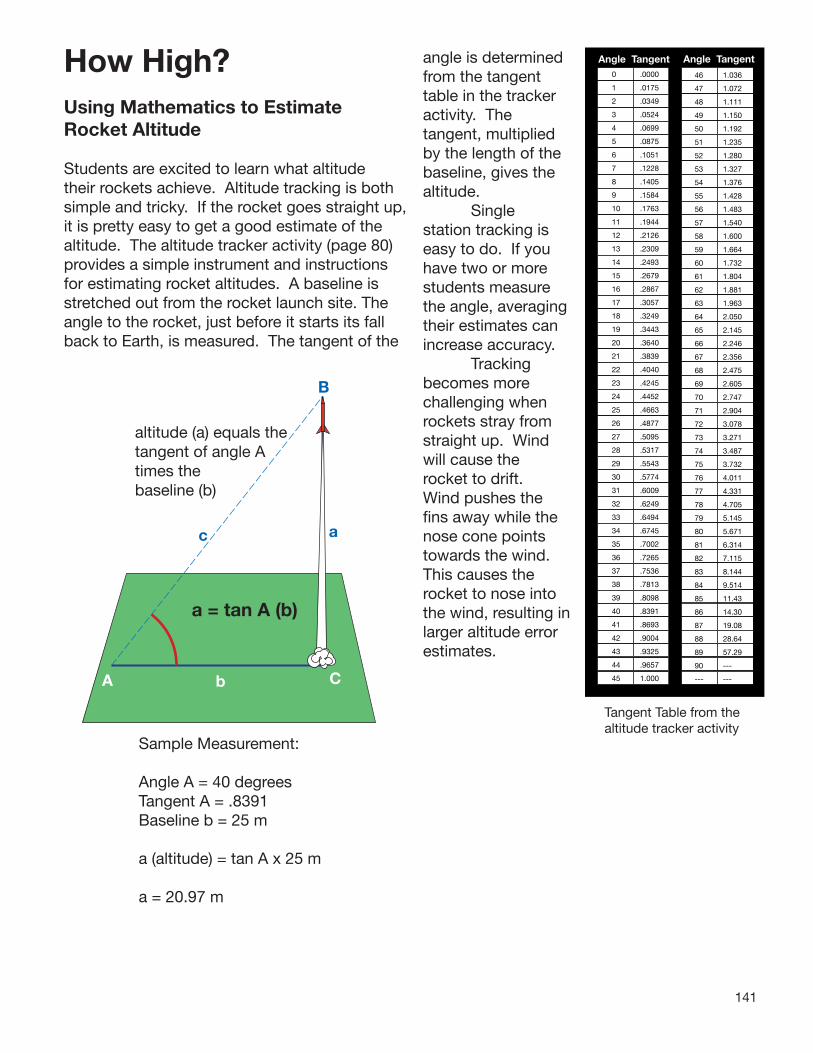
141
How High?Using Mathematics to Estimate Rocket Altitude
Students are excited to learn what altitude their rockets achieve. Altitude tracking is both simple and tricky. If the rocket goes straight up, it is pretty easy to get a good estimate of the altitude. The altitude tracker activity (page 80) provides a simple instrument and instructions for estimating rocket altitudes. A baseline is stretched out from the rocket launch site. The angle to the rocket, just before it starts its fall back to Earth, is measured. The tangent of the
angle is determined from the tangent table in the tracker activity. The tangent, multiplied by the length of the baseline, gives the altitude. Single station tracking is easy to do. If you have two or more students measure the angle, averaging their estimates can increase accuracy. Tracking becomes more challenging when rockets stray from straight up. Wind will cause the rocket to drift. Wind pushes the fins away while the nose cone points towards the wind. This causes the rocket to nose into the wind, resulting in larger altitude error estimates.
a
b
B
altitude (a) equals the tangent of angle A times the baseline (b)
c
a = tan A (b)
A C
Single Station - No Wind
Sample Measurement:
Angle A = 40 degreesTangent A = .8391Baseline b = 25 m
a (altitude) = tan A x 25 m
a = 20.97 m
Tangent Table from the altitude tracker activity
46 1.036
47 1.072
48 1.111
49 1.150
50 1.192
51 1.235
52 1.280
53 1.327
54 1.376
55 1.428
56 1.483
57 1.540
58 1.600
59 1.664
60 1.732
61 1.804
62 1.881
63 1.963
64 2.050
65 2.145
66 2.246
67 2.356
68 2.475
69 2.605
70 2.747
71 2.904
72 3.078
73 3.271
74 3.487
75 3.732
76 4.011
77 4.331
78 4.705
79 5.145
80 5.671
81 6.314
82 7.115
83 8.144
84 9.514
85 11.43
86 14.30
87 19.08
88 28.64
89 57.29
90 ---
--- ---
Angle Tangent Angle Tangent0 .0000
1 .0175
2 .0349
3 .0524
4 .0699
5 .0875
6 .1051
7 .1228
8 .1405
9 .1584
10 .1763
11 .1944
12 .2126
13 .2309
14 .2493
15 .2679
16 .2867
17 .3057
18 .3249
19 .3443
20 .3640
21 .3839
22 .4040
23 .4245
24 .4452
25 .4663
26 .4877
27 .5095
28 .5317
29 .5543
30 .5774
31 .6009
32 .6249
33 .6494
34 .6745
35 .7002
36 .7265
37 .7536
38 .7813
39 .8098
40 .8391
41 .8693
42 .9004
43 .9325
44 .9657
45 1.000

142
a
b
B
c
A C
WindB
ca
A b C
Wind
Single Station
Too Low !
Too High!
One method for reducing windy day error is to set up the baseline perpendicular to the wind direction. In the diagram that follows, wind causes the rocket to drift to the right. This stretches the baseline a bit but the overall error for the altitude is reduced. Challenge advanced students to come up with a way of determe how much the baseline changes when the rocket drifts to the right.
Altitude = two trees,28 concrete blocks, or two windows
Angle A is reduced but line b is increasedby the drift of the rocket.
B
a
C
b
A
Wind
a = tan A (b)
Single Station Tracking- with Wind
Direct Measurement
Wind effects can also be addressed by employing two tracking stations at opposite ends of the baseline. The baseline is stretched up and downwind. Each station measures the altitude the rocket achieves. Both stations calculate the altitude and divide by two.
Here is a different methods for estimating altitude that is appropriate for lower grade students launching rockets that don’t travel very high (e.g. straw rockets). Tracking students simply stand back and compare the rocket altitude to a building, tree, flagpole, etc.
Effects of Wind on
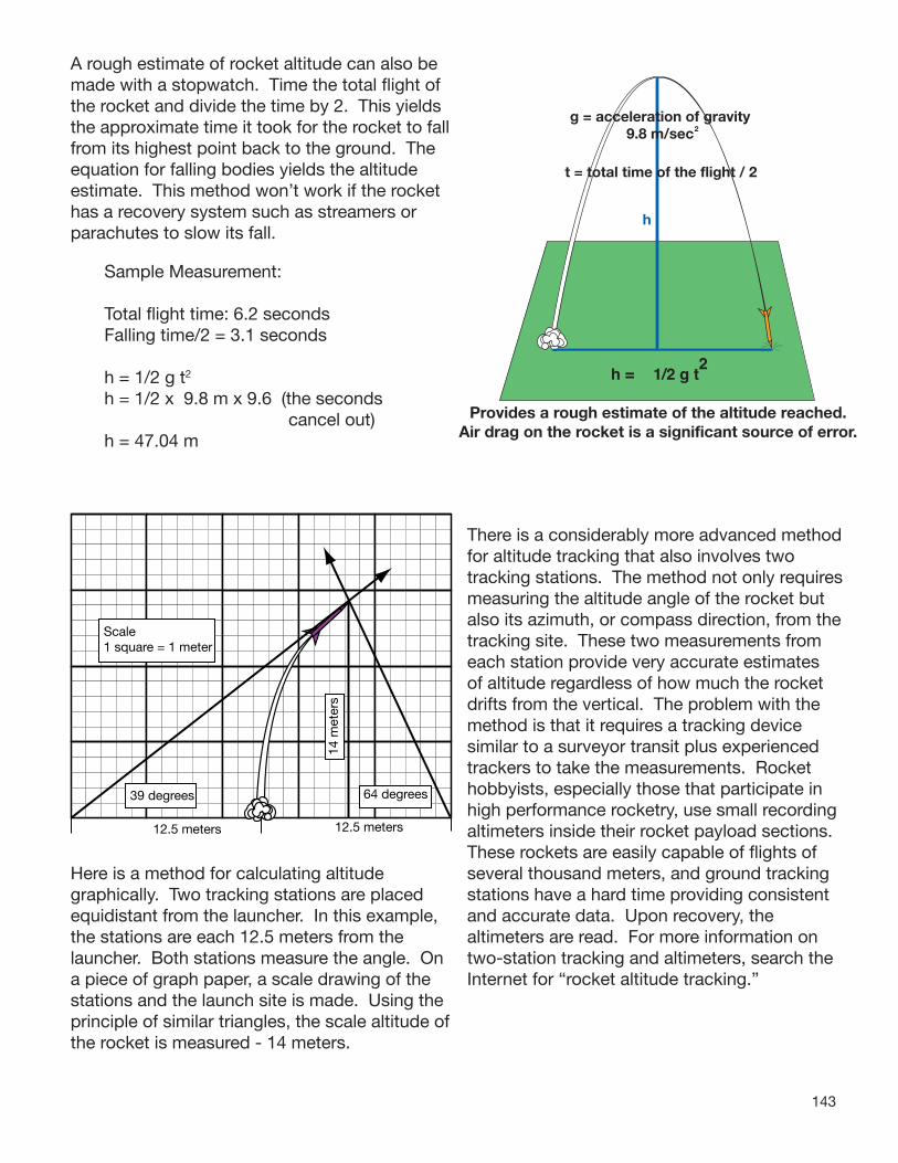
143
A rough estimate of rocket altitude can also be made with a stopwatch. Time the total flight of the rocket and divide the time by 2. This yields the approximate time it took for the rocket to fall from its highest point back to the ground. The equation for falling bodies yields the altitude estimate. This method won’t work if the rocket has a recovery system such as streamers or parachutes to slow its fall.
Sample Measurement:
Total flight time: 6.2 secondsFalling time/2 = 3.1 seconds
h = 1/2 g t2
h = 1/2 x 9.8 m x 9.6 (the seconds cancel out)h = 47.04 m
Provides a rough estimate of the altitude reached.Air drag on the rocket is a significant source of error.
h = 1/2 g t2
g = acceleration of gravity9.8 m/sec2
t = total time of the flight / 2
h
Time Tracking
Here is a method for calculating altitude graphically. Two tracking stations are placed equidistant from the launcher. In this example, the stations are each 12.5 meters from the launcher. Both stations measure the angle. On a piece of graph paper, a scale drawing of the stations and the launch site is made. Using the principle of similar triangles, the scale altitude of the rocket is measured - 14 meters.
Scale1 square = 1 meter
39 degrees 64 degrees
14 m
eter
s
12.5 meters 12.5 meters
There is a considerably more advanced method for altitude tracking that also involves two tracking stations. The method not only requires measuring the altitude angle of the rocket but also its azimuth, or compass direction, from the tracking site. These two measurements from each station provide very accurate estimates of altitude regardless of how much the rocket drifts from the vertical. The problem with the method is that it requires a tracking device similar to a surveyor transit plus experienced trackers to take the measurements. Rocket hobbyists, especially those that participate in high performance rocketry, use small recording altimeters inside their rocket payload sections. These rockets are easily capable of flights of several thousand meters, and ground tracking stations have a hard time providing consistent and accurate data. Upon recovery, the altimeters are read. For more information on two-station tracking and altimeters, search the Internet for “rocket altitude tracking.”
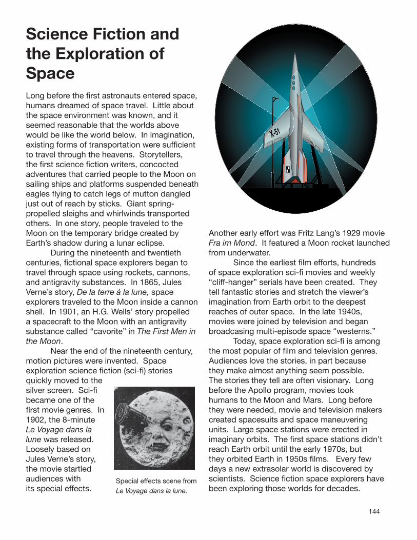
144
Science Fiction and the Exploration of SpaceLong before the fi rst astronauts entered space, humans dreamed of space travel. Little about the space environment was known, and it seemed reasonable that the worlds above would be like the world below. In imagination, existing forms of transportation were suffi cient to travel through the heavens. Storytellers, the fi rst science fi ction writers, concocted adventures that carried people to the Moon on sailing ships and platforms suspended beneatheagles fl ying to catch legs of mutton dangled just out of reach by sticks. Giant spring-propelled sleighs and whirlwinds transported others. In one story, people traveled to the Moon on the temporary bridge created by Earth’s shadow during a lunar eclipse. During the nineteenth and twentieth centuries, fi ctional space explorers began to travel through space using rockets, cannons, and antigravity substances. In 1865, Jules Verne’s story, De la terre á la lune, space explorers traveled to the Moon inside a cannon shell. In 1901, an H.G. Wells’ story propelled a spacecraft to the Moon with an antigravity substance called “cavorite” in The First Men in the Moon. Near the end of the nineteenth century, motion pictures were invented. Space exploration science fi ction (sci-fi ) stories quickly moved to the silver screen. Sci-fi became one of the fi rst movie genres. In 1902, the 8-minute Le Voyage dans la lune was released. Loosely based on Jules Verne’s story, the movie startled audiences with Special effects scene from its special effects. Le Voyage dans la lune.
X-51
Another early effort was Fritz Lang’s 1929 movie Fra im Mond. It featured a Moon rocket launched from underwater. Since the earliest fi lm efforts, hundreds of space exploration sci-fi movies and weekly “cliff-hanger” serials have been created. They tell fantastic stories and stretch the viewer’s imagination from Earth orbit to the deepest reaches of outer space. In the late 1940s, movies were joined by television and began broadcasing multi-episode space “westerns.” Today, space exploration sci-fi is among the most popular of fi lm and television genres. Audiences love the stories, in part because they make almost anything seem possible. The stories they tell are often visionary. Long before the Apollo program, movies took humans to the Moon and Mars. Long before they were needed, movie and television makers created spacesuits and space maneuvering units. Large space stations were erected in imaginary orbits. The fi rst space stations didn’t reach Earth orbit until the early 1970s, but they orbited Earth in 1950s fi lms. Every few days a new extrasolar world is discovered by scientists. Science fi ction space explorers have been exploring those worlds for decades.

145
However improbable and dopey some of the early special effects may now seem, space exploration movies and television have much to offer. Comparing the science and technology Scene from Fra im Mond.
they present to real space exploration is a fascinating endeavor. What has turned out to be real and actually happened? What hasn’t happened yet? What is scientifically correct? What is scientifically incorrect or just plain silly? Regardless of their scientific and technological authenticity, space exploration movies and television energize the imagination. They have excited the masses and have helped generate popular support that makes real space exploration possible.
Opportunities for Student ResearchSpace exploration sci-fi offers students interesting and entertaining research lines. Telling the difference between good and bad science and technology requires knowing good science and technology. Have students select a movie and review it for the science and technology presented. The following are a few questions students might try to answer in their reviews:
• What is the movie’s title?• When was the movie made?• What is the plot (story) of the movie?• How was space travel accomplished? • Describe the vehicle used. What was its
power source?• Did the movie employ real science and
technology? Give some examples.• Did the movie make science and technology
mistakes? Give some examples.• Has NASA used similar science and
technology to explore space? Explain.• Did the movie accurately predict the future?
Give some examples of how.
Here are a few suggested movies for students to review. All are available on DVDs from rental stores and online rental stores.
Rocketship XM (1950) Engine and fuel problems during flight cause Rocketship XM to zoom its crew past its original target, the Moon, and arrive at Mars instead. G forces and a destroyed Martian civilization are some of the challenges faced by the crew.
Conquest of Space (1956) A space crew onboard a spinning wheel space station uses a space taxi during space walks to prepare their ship for launch. On its way to Mars, the crew dodges a flaming asteroid and deals with emotional problems.
Forbidden Planet (1956)Humans travel by flying saucer to a distant world and meet their inner selves.
First Men in the Moon (1964)An H. G. Wells story adaptation carries two accidental space travelers and an eccentric scientist to the Moon in an antigravity-propelled space sphere.
2001 A Space Odyssey (1968), 2010 (1984)In a series of slow-moving visual experiences, humans travel to the Moon and Jupiter to follow mysterious alien signs. The film predicts space hotels and multi-year space missions.
Star Wars, Episodes I - VII ( 1977 - 2005)Rebel forces battle an evil empire across a galaxy far, far away. A wide range of space vehicles, robots, and alien life sustain the action.
Star Trek (1979 - 2002)In a series of movies Captains Kirk and Picard save Earth and strive for peace in the galaxy. Using warp drive and transporters, they boldly go where no humans have gone before.

146
The Art of Spacefl ightSpace art has long been a key part of the exploration of space. In the 1950s, space artists such as Chesley Bonestell illustrated space exploration concepts for books and magazine articles. At the same time, animation artists at Disney Studios, working with space experts such as Dr. Werner von Braun, showed what the fi rst missions to space, the Moon, and beyond might look like. The American public was enchanted by dreams of spacefl ight, and the American effort to explore outer space was born. Space art continues to support the exploration of space. Besides promoting mission concepts with decision makers and the public, space art also provides scientists, engineers, and technicians a concept picture of what they are trying to do. They see what the myriad systems they are working on look like assembled together. Furthermore, space art excites and motivates students to pursue careers in science, technology, engineering, and mathematics. Early space art was created using traditional materials and techniques. Many space artists still portray their dreams this way, but computer art has also found a place in space art. Spacecraft are created using wire-frame technology that permits them to be rotated, enlarged or reduced, and brought forward or backward and layered on one of many backgrounds. To create excitement, space artists often take advantage of forced perspective. Seeing a rocket launched from above provides a unique and exciting experience for the viewer. To create such a view, a horizon line and a vanishing point are laid out on the canvas or screen. Lines merging into the vanishing point provide guides for the 3D effect. Rockets, drawn within the lines, appear to go into or out of the picture. Invite students to create their own space art. Space art begins with a mission.
he horizoint for the lower
Tpt
on line and vanishing his illustration is just off right corner of the canvas.
NASA artist’s concept for Ares I launch
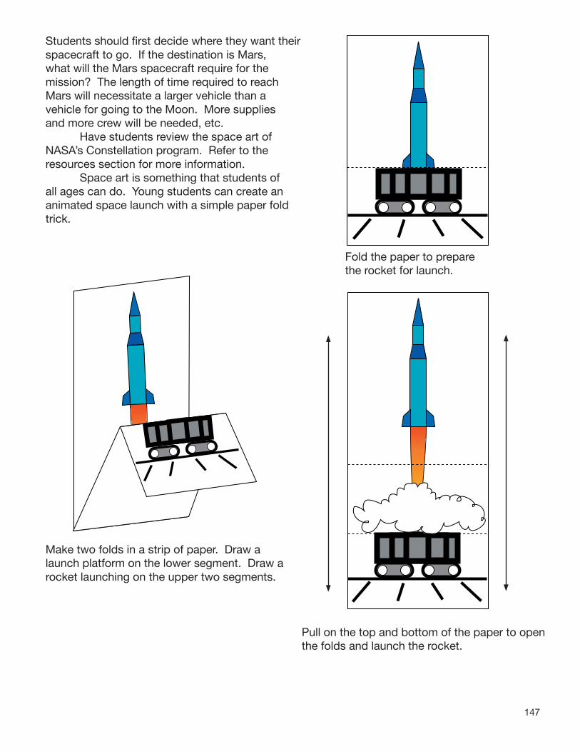
147
Students should first decide where they want their spacecraft to go. If the destination is Mars, what will the Mars spacecraft require for the mission? The length of time required to reach Mars will necessitate a larger vehicle than a vehicle for going to the Moon. More supplies and more crew will be needed, etc. Have students review the space art of NASA’s Constellation program. Refer to the resources section for more information. Space art is something that students of all ages can do. Young students can create an animated space launch with a simple paper fold trick.
Make two folds in a strip of paper. Draw a launch platform on the lower segment. Draw a rocket launching on the upper two segments.
Fold the paper to prepare the rocket for launch.
Pull on the top and bottom of the paper to open the folds and launch the rocket.
148
Rocket Glossary
Action - A force (push or pull) acting on an object. See Reaction.Altair - The name of NASA’s future lunar landingcraft.Altitude - The height above Earth achieved by arocket or other vehicle.Ares I and IV - NASA’s new rockets for 21st century space exploration.Attitude Control Rockets - Small rockets that are used as active controls to change the direction (attitude) a rocket is facing in space.Balanced Force - A force that is counterbalanced by an opposing force, resulting in no change in motion.Canards - Small movable fins located towards the nose cone of a rocket.Case - The body of a solid propellant rocket that holds the propellant.Center of Mass - The point in an object about which the object’s mass is centered.Center of Pressure - The point on the surface of an object about which the object’s surface area is centered.Combustion Chamber - A cavity inside a rocket where propellants burn.Compressed - Material that is forced into a smaller space than normal.Drag - Friction forces in the atmosphere that “drag” on a rocket to slow its flight.Fins - Arrow-like wings at the lower end of a rocket that stabilize the rocket in flight.Gimbaled Nozzles - Tiltable rocket nozzles used for active flight control.Igniter - A device that ignites a rocket’s engines.Liquid Propellant - Rocket propellants in liquid form.Mass - The amount of matter contained in an object.Mass Fraction - The mass of propellants in a rocket divided by the rocket’s total mass.Microgravity - An environment that imparts to an object a net acceleration that is small
compared to what is produced by Earth at its surface.Motion - Movement of an object in relation to its surroundings.Movable Fins - Rocket fins that can move to stabilize a rocket’s flight.Newton’s Laws of Motion - Laws governing all motion and in particular rocket flight.Nose Cone - The cone-shaped front end of a rocket.Nozzle - A bell-shaped opening at the lower end of a rocket engine through which a stream of hot gases is directed.Orion - The name of NASA’s planned orbital spacecraft.Oxidizer - A chemical containing oxygen compounds that permit rocket fuel to burn in the atmosphere and space.Passive Controls - Stationary devices, such as fixed fins, that stabilize a rocket in flight.Payload - The cargo carried by a rocket.Propellant - A mixture of fuel and oxidizer that burns to produce rocket thrust.Reaction - A movement in the opposite direction from the imposition of an action. See Action.Rest - The absence of movement of an object in relation to its surroundings.Solid Propellant - Rocket fuel and oxidizer in solid form.Space Station - An orbital laboratory.Stability - A measure of the smoothness of the flight of the rocket.Stages - Two or more rockets stacked on top of each other in order to reach a higher altitude or have a greater payload capacity.Throat - The narrow opening of a rocket nozzle.Thrust - The force from a rocket engine that propels it.Unbalanced Force - A force that is not countered by another force in the opposite direction.
149
NASA Resources
The National Aeronautics and Space Administration has an amazing collection of resources for the classroom. Hundreds of educator guides, fact sheets, posters, and lithographs have been developed for classrooms and are available for electronic downloads. Photo and video collections chronicling NASA’s more than 50 years of aerospace research and exploration are also available. Information about current and future programs, including NASA’s space exploration policy for the 21st century, can be obtained by electronically stepping through NASA’s Internet portal. To speed you and your students on your way to your space exploration adventure, some of the links within the NASA portal are highlighted below.
NASA Portal: This is where the adventure begins.
http://www.nasa.gov/home/index.html
NASA’s Constellation Program: Learn about the Ares rockets, Orion and Altair, launch schedules, and more:
http://www.nasa.gov/mission_pages/constellation/ares/index.html
NASA’s Exploration Program: Explore NASA’s plans for permanent bases on the Moon, expeditions to Mars, robotic spacecraft, and missions to all points beyond:
http://www.nasa.gov/mission_pages/constellation/main/index.html
NASA Education: This is the place to learn about NASA’s wide-ranging formal and informal education programs for students and educators and download curriculum materials, videos, and podcasts:
http://education.nasa.gov/home/index.html
NASA Educational Resources: In addition to the on-line educational resource materials, NASA supports Educator Resource Centers in all states. This site lists the location and contact information for each site.
http://www.nasa.gov/audience/foreducators/k-4/contacts/ERCN_State_Listing.html
NASA Centers and Research Facilities: Here are the places you can go to see NASA in action.
http://www.nasa.gov/about/sites/index.html
Contact NASA: Learn more about the resources available to you, including training opportunities with these addresses.
http://education.nasa.gov/edoffices/overview/index.html

150
NASA Media: Access the extensive photographic and video collections of NASA at these sites:
NASA Image Exchange http://nix.nasa.gov/
Great Images In NASA http://grin.hq.nasa.gov/
Kennedy Space Center http://mediaarchive.ksc.nasa.gov/index.cfm Dryden Flight Research Center http://www.dfrc.nasa.gov/Gallery/index.html
Everything NASA http://www.nasa.gov/multimedia/imagegallery/index.html
Destinations in Space http://photojournal.jpl.nasa.gov/index.html

151stud
ents
in s
cien
ce, m
athe
mat
ics,
and
tec
hnol
ogy.
NA
SA
con
tinua
lly s
eeks
to
invo
lve
the
educ
atio
nal c
omm
unity
in t
he d
evel
opm
ent
and
imp
rove
men
t of
its
educ
atio
nal p
rod
ucts
and
pro
gram
s. Y
our
opin
ions
and
sug
gest
ions
are
bot
h vi
tal
and
ap
pre
ciat
ed.
Ple
ase
take
a fe
w m
inut
es t
o sh
are
your
tho
ught
s an
d id
eas
with
us.
Whe
n co
mp
lete
, ple
ase
send
thi
s fo
rm t
o th
e ad
dre
ss o
n th
e ot
her
sid
e.
Than
k yo
u fo
r yo
ur a
ssis
tanc
e an
d s
upp
ort.
Ple
ase
tell
us a
litt
le a
bo
ut y
ou.
Wha
t is
you
r p
ositi
on?
(Che
ck a
ll th
at a
pp
ly)
In w
hat
sub
ject
(s) a
nd g
rad
e le
vels
(s) d
id y
ou u
se t
his
guid
e?
Sub
ject
(s):
Gra
de
Leve
l(s):
Whe
re d
o yo
u liv
e?
Ple
ase
shar
e yo
ur o
pin
ions
ab
out
thi
s ed
ucat
or
gui
de.
Ove
rall,
how
wou
ld y
ou r
ate
this
gui
de
for
your
use
?
Valu
able
Not
Res
ourc
e
Use
ful
Teac
her
R
esou
rce
C
urric
ulum
Tea
cher
S
pec
ialis
t
Ad
min
istr
ator
Mus
eum
/Sci
ence
Hom
e S
choo
l
C
ente
r E
duc
ator
Oth
er (p
leas
e d
escr
ibe)
5
4
3
2
1
EG
-200
8-05
-060
-KS
C
RO
CK
ET
SE
duc
ato
r’s G
uid
e w
ith
Act
ivit
ies
in S
cien
ce, T
echn
olo
gy,
E
ngin
eeri
ng, a
nd M
athe
mat
ics
Y C
AR
DT
OR
RE
PL
ED
UC
A
The
goal
of t
his
educ
ator
gui
de
is t
o b
e a
valu
able
res
ourc
e fo
r te
ache
rs a
nd
Wou
ld y
ou r
ecom
men
d t
his
guid
e to
a c
olle
ague
?
Ye
s
May
be
No
Why
?
Wha
t p
arts
of t
his
guid
e w
ere
mos
t ef
fect
ive
for
you?
Ple
ase
shar
e yo
ur t
houg
hts
on h
ow t
his
guid
e ca
n b
e im
pro
ved
.
Ad
diti
onal
Com
men
ts:
Aga
in, t
hank
you
for
your
ass
ista
nce
and
sup
por
t.
Please Fold Along Line and Tape Closed
152
Please Fold Along Line and Tape Closed
Please PlaceStamp HerePost Office
Will Not DeliverWithout Proper
Postage
National Aeronautics and Space Administration Kennedy Space Center Pre-College OfficerMailcode: XA-DKennedy Space Center, Fl 32899

153
National Aeronautics and Space Administration Kennedy Space Center Pre-College OfficerMailcode: XA-DKennedy Space Center, Fl 32899
Please PlaceStamp HerePost Office
Will Not DeliverWithout Proper
Postage
Please Fold Along Line and Tape Closed
John F. Kennedy Space CenterKennedy Space Center FL 32899
www.nasa.gov
EG-2008-05-060-KSC 154