General Archi ec ural Design Gui elines · General Architectural Design Guidelines, the majority of...
39
General Archi�ec�ural Design Gui�elines (2011 ���a�e� prepared for: Municipality of Clarington prepared by: John G. Williams Limited Architect March 2011 Project No.: w-1142
Transcript of General Archi ec ural Design Gui elines · General Architectural Design Guidelines, the majority of...
General Archi�ec�ural Design Gui�elines
(2011 ���a�e�
prepared for: Municipality of Clarington
prepared by: John G. Williams Limited
Architect
March 2011 Project No.: w-1142
G E N E R A L A R C H I T E C T U R A L D E S I G N G U I D E L I N E S ( 2 0 1 1 U P D AT E )
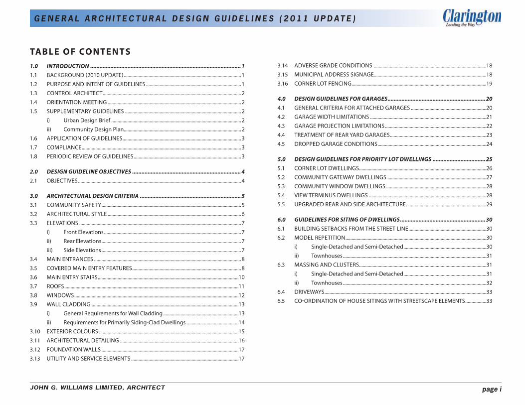
TABLE OF CO NTE NTS
1.0 INTRODUCTION ................................................................................................. 1 1.1 BACKGROUND (2010 UPDATE)...............................................................................................1
1.2 PURPOSE AND INTENT OF GUIDELINES .............................................................................1
1.3 CONTROL ARCHITECT................................................................................................................2
1.4 ORIENTATION MEETING ............................................................................................................2
1.5 SUPPLEMENTARY GUIDELINES ..............................................................................................2
i) Urban Design Brief .........................................................................................................2
ii) Community Design Plan...............................................................................................2
1.6 APPLICATION OF GUIDELINES................................................................................................3
1.7 COMPLIANCE.................................................................................................................................3
1.8 PERIODIC REVIEW OF GUIDELINES.......................................................................................3
2.0 DESIGN GUIDELINE OBJECTIVES ...................................................................... 4 2.1 OBJECTIVES....................................................................................................................................4
3.0 ARCHITECTURAL DESIGN CRITERIA ................................................................. 5 3.1 COMMUNITY SAFETY.................................................................................................................5
3.2 ARCHITECTURAL STYLE ............................................................................................................6
3.3 ELEVATIONS ...................................................................................................................................7
i) Front Elevations ...............................................................................................................7
ii) Rear Elevations .................................................................................................................7
iii) Side Elevations .................................................................................................................7
3.4 MAIN ENTRANCES .......................................................................................................................8
3.5 COVERED MAIN ENTRY FEATURES........................................................................................8
3.6 MAIN ENTRY STAIRS..................................................................................................................10
3.7 ROOFS.............................................................................................................................................11
3.8 WINDOWS.....................................................................................................................................12
3.9 WALL CLADDING .......................................................................................................................13
i) General Requirements for Wall Cladding .............................................................13
ii) Requirements for Primarily Siding-Clad Dwellings ..........................................14
3.10 EXTERIOR COLOURS .................................................................................................................15
3.11 ARCHITECTURAL DETAILING ................................................................................................16
3.12 FOUNDATION WALLS ...............................................................................................................17
3.13 UTILITY AND SERVICE ELEMENTS .......................................................................................17
3.14 ADVERSE GRADE CONDITIONS ...........................................................................................18
3.15 MUNICIPAL ADDRESS SIGNAGE...........................................................................................18
3.16 CORNER LOT FENCING.............................................................................................................19
4.0 DESIGN GUIDELINES FOR GARAGES...............................................................20 4.1 GENERAL CRITERIA FOR ATTACHED GARAGES .............................................................20
4.2 GARAGE WIDTH LIMITATIONS ..............................................................................................21
4.3 GARAGE PROJECTION LIMITATIONS..................................................................................22
4.4 TREATMENT OF REAR YARD GARAGES..............................................................................23
4.5 DROPPED GARAGE CONDITIONS........................................................................................24
5.0 DESIGN GUIDELINES FOR PRIORITY LOT DWELLINGS ..................................25 5.1 CORNER LOT DWELLINGS.......................................................................................................26
5.2 COMMUNITY GATEWAY DWELLINGS ................................................................................27
5.3 COMMUNITY WINDOW DWELLINGS .................................................................................28
5.4 VIEW TERMINUS DWELLINGS ...............................................................................................28
5.5 UPGRADED REAR AND SIDE ARCHITECTURE.................................................................29
6.0 GUIDELINES FOR SITING OF DWELLINGS.......................................................30 6.1 BUILDING SETBACKS FROM THE STREET LINE...............................................................30
6.2 MODEL REPETITION..................................................................................................................30
i) Single-Detached and Semi-Detached ...................................................................30
ii) Townhouses ....................................................................................................................31
6.3 MASSING AND CLUSTERS.......................................................................................................31
i) Single-Detached and Semi-Detached ...................................................................31
ii) Townhouses ....................................................................................................................32
6.4 DRIVEWAYS...................................................................................................................................33
6.5 CO-ORDINATION OF HOUSE SITINGS WITH STREETSCAPE ELEMENTS .................33
JOHN G. WILLIAMS LIMITED, ARCHITECT page i
G E N E R A L A R C H I T E C T U R A L D E S I G N G U I D E L I N E S ( 2 0 1 1 U P D AT E )
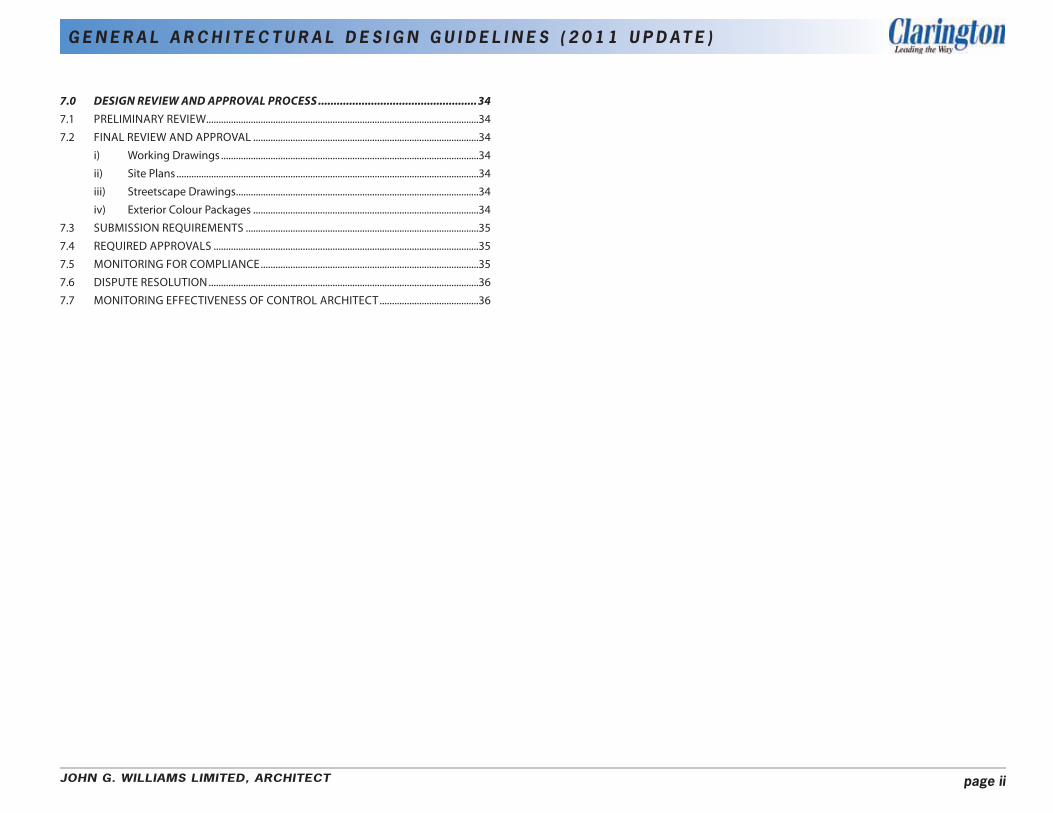
7.0 DESIGN REVIEW AND APPROVAL PROCESS ...................................................34 7.1 PRELIMINARY REVIEW..............................................................................................................34
7.2 FINAL REVIEW AND APPROVAL ...........................................................................................34
i) Working Drawings ........................................................................................................34
ii) Site Plans ..........................................................................................................................34
iii) Streetscape Drawings ..................................................................................................34
iv) Exterior Colour Packages ...........................................................................................34
7.3 SUBMISSION REQUIREMENTS ..............................................................................................35
7.4 REQUIRED APPROVALS ...........................................................................................................35
7.5 MONITORING FOR COMPLIANCE........................................................................................35
7.6 DISPUTE RESOLUTION .............................................................................................................36
7.7 MONITORING EFFECTIVENESS OF CONTROL ARCHITECT........................................36
JOHN G. WILLIAMS LIMITED, ARCHITECT page ii
G E N E R A L A R C H I T E C T U R A L D E S I G N G U I D E L I N E S ( 2 0 1 1 U P D AT E )
1.0 INTRODUC TION
1.1 B AC KG R O U N D ( 2010 U P D AT E )
The Municipality of Clarington is located about 50 kilometres east of Toronto, within the Greater Toronto Area, and covers an area of approximately 608 square kilometres. This primarily rural municipality contains 4 urban communities: • Bowmanville • Courtice • Newcastle Village • Orono
In May 2002 the Municipality of Clarington adopted “General Architectural Design Guidelines” and the requirement for a privately-administered architectural design review process for all new housing within the Municipality - a process similar to that used by most other municipalities within the Greater Toronto Area. The architectural control process has been considered largely successful in achieving an enhanced streetscape quality and improving the design of housing for new residential developments within Clarington. However, as recommended in the “General Architectural Design Guidelines” (May 2002) a periodic review of the document and the architectural control process is required to ensure they are kept current and effective in meeting Clarington’s civic design objectives with respect to new residential built form.
John G. Williams Limited Architect was retained by the Municipality to review and update the General Architectural Design Guidelines based upon: • Touring recently constructed local communities to determine strengths
and weaknesses with current Guidelines and review process. • Adjusting architectural design criteria to be more effective in producing
desired results. • Adding more stringent architectural design criteria where necessary. • Providing better graphic representation of design concepts.
• Modify the architectural design review process to ensure greater municipal input.
• Consultation with the local development industry and with municipal staff.
Although the format and graphics provide a new look for Clarington’s General Architectural Design Guidelines, the majority of the content remains pertinent and thus unchanged from the original May 2002 document.
1.2 PURPOSE AND INTENT OF GUIDELINES
The Municipality of Clarington Official Plan states:
“Excellence in urban design will be pursued to contribute to a sense of place, ensure physical safety, promote social interaction and enjoyment, provide human scale to the urban environment and promote the integration of land uses.”
To ensure that municipal objectives are achieved, Clarington Council requires a full architectural review process to be applied throughout Clarington. The integration of good urban design principles, including planning, architecture and landscape architecture initiatives, will help to promote healthy, attractive, livable communities with a positive identity.
The purpose of Architectural Design Guidelines is to encourage the design and construction of houses which harmonize with their surroundings and which demonstrate a high standard of quality. They are intended to establish a community design vision for new residential development throughout the Municipality of Clarington and to provide the guidance necessary to achieve that vision.
It is important for Guidelines to take into consideration geographic location and to recognize that Clarington’s target market is often drawn from the Greater Toronto Area, attracted by affordable housing. It is also necessary to recognize the role that the automobile plays in suburban society today. The challenge is to create transit oriented design in appropriate locations in keeping with the framework of Places to Grow legislation.
JOHN G. WILLIAMS LIMITED, ARCHITECT page 1

G E N E R A L A R C H I T E C T U R A L D E S I G N G U I D E L I N E S ( 2 0 1 1 U P D AT E )
1.3 CONTROL ARCHITECT
Every plan of subdivision shall be required to have a Control Architect. Qualified architects must be registered with the Ontario Association of Architects and must not have any conflict of interest in their role as Control Architect. In order to qualify, architects shall demonstrate relevant experience in the field of architectural control within the GTA. The selection of the Control Architect will be made by the Developer and must be acceptable to the Municipality.
The architectural review process by the Control Architect will be conducted expeditiously and fairly. It shall generally comprise the following steps: • Preparation of Supplementary Urban Design Documents; • Model review and approval; and • Monitoring for compliance.
These Guidelines and their interpretation by the Control Architect are intended to provide for sufficient flexibility to encourage design creativity and innovation. Proposed designs which are not in total compliance with the guidelines will be considered by the Control Architect, based on their merits, and may be approved where the spirit and intent of the guidelines is maintained.
Builder’s are responsible for paying all required fees directly to the Control Architect. Further information on the design review and approval process is described in Section 7.0 of these Guidelines.
1.4 O R I E N TAT I O N MEETING
Prior to the review of housing designs, a meeting shall occur between the Municipality, the Control Architect and the Applicant (developer / builder / architectural or urban design consultant) to discuss the design vision for the new development. The purpose of this meeting is to encourage dialogue on the expectations of each stakeholder and to ensure the Municipality’s civic design objectives are being appropriately fulfilled. During this meeting the Municipality and the Control Architect can provide feedback and guidance on the initial development proposal. The meeting should cover the following subjects:
• Community design vision / neighbourhood identity • Proposed Architecture • Proposed Landscaping • Proposed Final Site Grades • Supplementary Guidelines (Urban Design Brief / Community Design
Plan)
1.5 SUPPLEMENTARY G U I D E L I N E S
In addition to the design criteria contained in the Municipality of Clarington General Architectural Design Guidelines, each new development will require a site-specific document to be prepared for review and approval by the Director of Planning Services. The content of these supplementary guidelines is dependant upon the nature and scale of the proposed development and may take the form of an “Urban Design Brief” or “Community Design Plan”.
i) Urban Design Brief
Small stand-alone subdivisions or infill sites will require a 1-2 page “Urban Design Brief” that will include the following: • A brief description of the property including location and community
context. • A Priority Lot Map, indicating lots which have special design
requirements due to their location and degree of public visibility, (i.e. community gateways, corner lots, park lots, etc.).
• Any proposed variations from the architectural standards as stated within the Municipality of Clarington General Architectural Design Guidelines (i.e. a special architectural theme).
ii) Community Design Plan
Major development areas, such as large-scale subdivisions or Secondary Plan Areas, will require a “Community Design Plan” to articulate a cohesive community vision that will include the following: • A description of the property(s) including location and community
context. • Community urban design vision (to apply to all subdivisions and
JOHN G. WILLIAMS LIMITED, ARCHITECT page 2
G E N E R A L A R C H I T E C T U R A L D E S I G N G U I D E L I N E S ( 2 0 1 1 U P D AT E )
developers within the community). • Unified treatment of public realm elements throughout the community
(i.e. gateway / community edge treatments, fencing, street furniture, lighting, etc.).
• Treatment of special character areas and feature streets, including connections of walkways and bicycle trails within the community, where applicable.
• Description of architectural themes with flexibility to allow for different architectural styles.
• A Priority Lot Map, indicating lots which have special design requirements due to their location and degree of public visibility, (i.e. community gateways, corner lots, park lots, etc.).
• Any proposed variations from the architectural standards as stated within the Municipality of Clarington General Architectural Design Guidelines (i.e. a special architectural theme).
Since large scale communities are often comprised of a group of several different developers commencing at varying times, it is important that the “Community Design Plan” provide sufficient flexibility to accommodate for change and innovation.
1.6 APPLICATION OF GUIDELINES
These Guidelines shall apply to every plan of subdivision within the Municipality of Clarington save and except for the following: • Industrial plans of subdivision; • Country residential (Estate) or Hamlet Residential plans of subdivision,
unless requested by the Municipality;
These Guidelines are intended for use by the initial builder of the dwelling and will not bind the homeowner or subsequent homeowners from making any alterations to the dwelling, provided they comply with all other governing regulations.
1.7 COMPLIANCE
In addition to the provisions of the Zoning By-law, the Conditions of Draft Approval, the Subdivision Agreement and all other applicable agreements and legislation, Developers and Builders are required to comply with these Guidelines and the Policy on New Home Sales Facilities throughout the design, marketing and construction process. Approvals by the Control Architect do not release the Builder from complying with the requirements of the Municipality of Clarington, the Project Engineer or any other approval authority.
Only those dwelling designs which have been given approval by the Control Architect shall be offered for sale.
1.8 PERIODIC REVIEW OF GUIDELINES
Over the course of time, further modifications to these General Architectural Design Guidelines may be necessary to address unforeseen issues (i.e changes to current construction practices). A periodic review of these Guidelines will be conducted by the Municipality of Clarington to ensure they are kept current and effective.
JOHN G. WILLIAMS LIMITED, ARCHITECT page 3

G E N E R A L A R C H I T E C T U R A L D E S I G N G U I D E L I N E S ( 2 0 1 1 U P D AT E )
2.0 DESIGN GUIDELINE OBJECTIVES
2.1 OBJECTIVES
The objectives of the Guidelines are:
• To encourage harmonious and attractive streetscapes through attention to the exterior architectural quality and appearance of new housing.
• To encourage safe, pedestrian-friendly streetscapes by promoting the principles of CPTED (Crime Prevention Through Environmental Design).
• To diminish the visual prominence of the garage within the streetscape.
• To encourage a variety of attractive, cost effective and innovative building designs which combine the best of contemporary and traditional design thinking.
• To establish the appropriate siting of buildings within the limitations of the zoning by-law having regard for dwelling type, size, architectural style and location within the community.
• To establish design requirements for buildings in highly visible locations.
• To assist Builders in the preparation of acceptable building designs.
• To establish procedures for: submission, review and approval of building designs; monitoring construction for compliance with the Guidelines; monitoring the effectiveness of the Control Architect; and dispute resolution.
• To establish processes that ensures that the Municipality’s civic design objectives are being met. This will include an orientation meeting between the Muncipality, the Developer / Builder and the Control Architect.
JOHN G. WILLIAMS LIMITED, ARCHITECT page 4

G E N E R A L A R C H I T E C T U R A L D E S I G N G U I D E L I N E S ( 2 0 1 1 U P D AT E )
3.0 ARCHITECTURAL DESIGN CRITERIA
3.1 COMMUNITY SAFETY
In order to promote safe, pedestrian-friendly communities, dwelling designs should incorporate principles of CPTED (Crime Prevention Through Environmental Design), including the following: • A clear definition between public and private space should be
provided through the design and placement of buildings, fencing and landscaping.
• Avoiding garage dominated streetscapes. • Ample fenestration facing public areas should be provided to
encourage casual surveillance (eyes on the street). • Site planning and building design should strive to maximize visual on-
look of public spaces. • Large, usable front porches should be included in the design of
dwellings to promote interactive outdoor spaces. • The front door should be visible from the street. • All entries to the dwelling should be well lit.
‘Eyes on the street’ Entries well lit Well scaled street lighting
BUILDINGS SHOULD BE DESIGNED TO PROVIDE “EYES ON THE STREET” AND PROMOTE COMMUNITY SAFETY
SITE PLANNING AND BUILDING DESIGN SHOULD ALLOW FOR VISUAL ON-LOOK OF PUBLIC SPACES
JOHN G. WILLIAMS LIMITED, ARCHITECT page 5

G E N E R A L A R C H I T E C T U R A L D E S I G N G U I D E L I N E S ( 2 0 1 1 U P D AT E )
3.2 ARCHITECTURAL STYLE
Clarington has many fine examples of traditional heritage homes which offer architectural design references for new construction within the Municipality. While it is not the intent of these guidelines to dictate specific architectural styles, Builders will be encouraged to employ a variety of architectural styles and building forms adapted from local architectural influences. The design of any building should have distinguishing elements characteristic of a single architectural style. Mixing discordant architectural styles within a single building is to be avoided.
Specific architectural styles should be addressed by the Developer / Builder in the supplementary guidelines. The goal is to ensure design compatibility among architectural styles within each individual subdivision and to establish a positive visual character for each new residential neighbourhood. To ensure this goal is achieved, the following design criteria will apply: • Builders should employ a palette of architectural styles and building
forms to ensure visual interest and continuity within the streetscape. Architectural variety needs to be balanced with harmony.
• Builders will be encouraged to provide architectural styles which help foster neighbourhood identity and sense of place within Clarington. The architectural style of buildings within the streetscape, in conjunction with the streetscape elements found within the public realm, plays a vital role in establishing the character of a street, a neighbourhood and a community.
EXAMPLES OF HISTORICAL ARCHITECTURE IN CLARINGTON (BOWMANVILLE)
ARCHITECTURAL STYLES SHOULD BE SELECTED TO CREATE INTERESTING STREETSCAPES THAT PROMOTE NEIGHBOURHOOD IDENTITY
JOHN G. WILLIAMS LIMITED, ARCHITECT page 6

G E N E R A L A R C H I T E C T U R A L D E S I G N G U I D E L I N E S ( 2 0 1 1 U P D AT E )
3.3 ELEVATIONS
i) Front Elevations The exterior appearance of new housing will have the greatest impact on the overall quality of new residential developments. Attractive, harmonious streetscapes are essential in creating a vibrant, livable community with a positive identity. To ensure this goal is achieved, the following design criteria will apply: • Variety of architectural expression among publicly exposed elevations
is encouraged. Further information on Model Repetition is described in Section 6.2 of these Guidelines.
• Each model is encouraged to have an alternative elevation. Popular models may require more than two elevations to avoid repetition and monotony within the streetscape.
• Individual buildings should combine to create visual harmony when sited together within the streetscape. This can be reinforced by use of complementary, but not identical, exterior materials, colours and architectural elements.
• Publicly exposed elevations shall incorporate adequate massing, proportions and wall openings (i.e. window, doors, porches, etc.) to avoid large, blank façades.
ii) Rear Elevations Rear elevation monotony should be avoided by limiting model designs with flat, uninteresting rear façades. To ensure this goal is achieved, the following is encouraged: • The majority of dwellings proposed by each builder within a
neighbourhood shall have variation of the rear wall plane. This can be achieved through the use of wall articulation such as wall jogs, bay windows, box-out windows or covered rear porches.
• Further enhancement will be required where rear elevations are exposed to public view (refer to Section 5.5).
iii) Side Elevations Side elevations facing the interior side lot line require no special design enhancement unless they are exposed to public view (refer to Section 5.5).
MODEL 1 - ELEVATION ‘A’ MODEL 1 - ELEVATION ‘B’
EXAMPLE OF ALTERNATE ELEVATIONS OF THE SAME MODEL
INDIVIDUAL BUILDINGS SHOULD COMBINE TO CREATE VISUAL HARMONY WHEN SITED TOGETHER WITHIN THE STREETSCAPE
REAR WALL ARTICULATION IS REQUIRED FOR THE MAJORITY OF DWELLINGS
JOHN G. WILLIAMS LIMITED, ARCHITECT page 7
G E N E R A L A R C H I T E C T U R A L D E S I G N G U I D E L I N E S ( 2 0 1 1 U P D AT E )
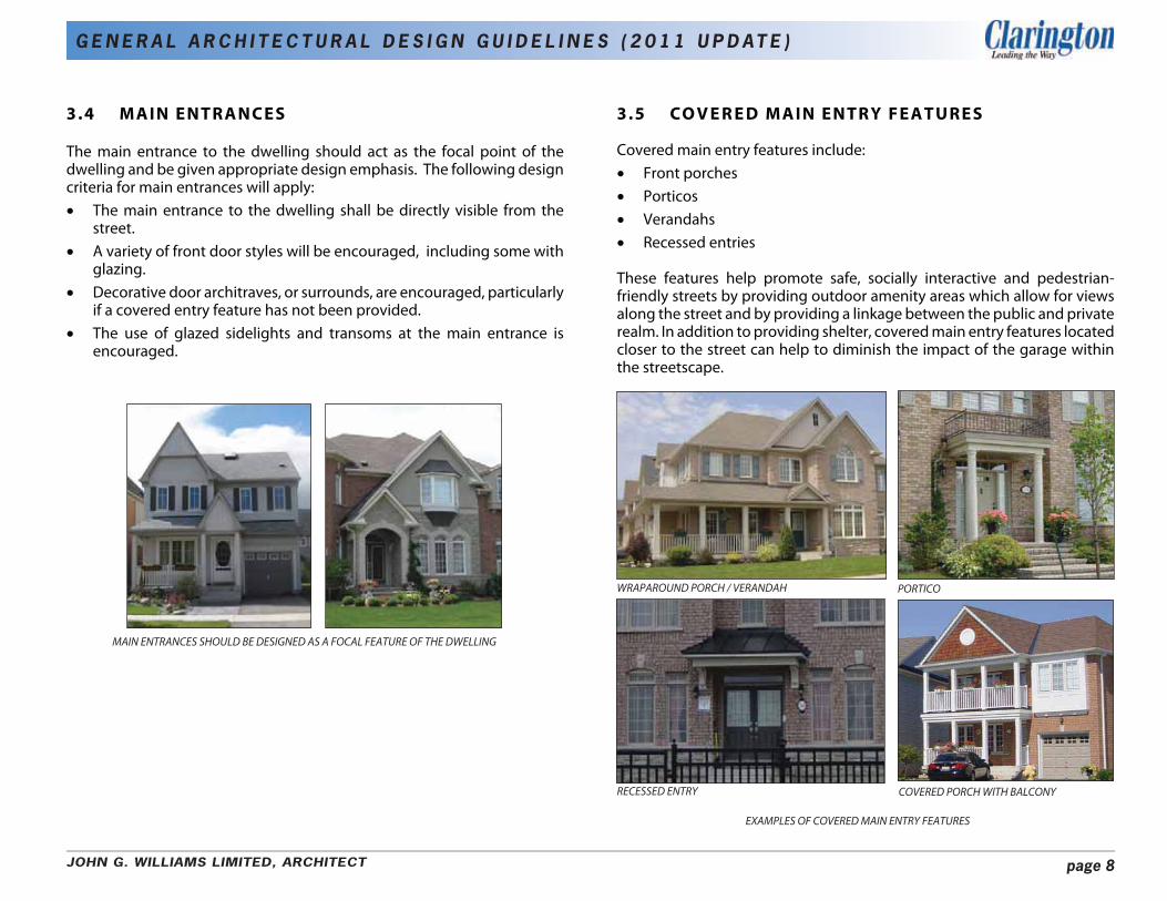
3.4 MAIN ENTRANCES
The main entrance to the dwelling should act as the focal point of the dwelling and be given appropriate design emphasis. The following design criteria for main entrances will apply: • The main entrance to the dwelling shall be directly visible from the
street. • A variety of front door styles will be encouraged, including some with
glazing. • Decorative door architraves, or surrounds, are encouraged, particularly
if a covered entry feature has not been provided. • The use of glazed sidelights and transoms at the main entrance is
encouraged.
3.5 CO V E R E D MAIN ENTRY FEATURES
Covered main entry features include: • Front porches • Porticos • Verandahs • Recessed entries
These features help promote safe, socially interactive and pedestrian-friendly streets by providing outdoor amenity areas which allow for views along the street and by providing a linkage between the public and private realm. In addition to providing shelter, covered main entry features located closer to the street can help to diminish the impact of the garage within the streetscape.
MAIN ENTRANCES SHOULD BE DESIGNED AS A FOCAL FEATURE OF THE DWELLING
WRAPAROUND PORCH / VERANDAH PORTICO
RECESSED ENTRY COVERED PORCH WITH BALCONY
EXAMPLES OF COVERED MAIN ENTRY FEATURES
JOHN G. WILLIAMS LIMITED, ARCHITECT page 8

G E N E R A L A R C H I T E C T U R A L D E S I G N G U I D E L I N E S ( 2 0 1 1 U P D AT E )
The following design criteria for covered main entry features will apply: • A covered entry feature is required for at least 50% of model designs
offered by each Builder. (If reductions to this percentage are contemplated due to a specific architectural theme, such as Georgian or Colonial, it must be addressed in the Supplementary Guidelines).
• Wraparound porches/verandahs are encouraged for Community Gateway Dwellings and Corner Lot Dwellings.
• Enhancements to emphasize the main entry are encouraged and may include pilasters, architraves or masonry surrounds.
• Covered front porch and/or verandah sizes should be maximized wherever possible. A minimum depth of 1.8m (6-0”) should be provided (unless constrained by zoning provisions) to comfortably accommodate chairs, however a variety of deeper porches are encouraged and expected.
• Porch column styles and widths should be consistent with the character of the house and should typically be no less than 200m (8”) square or diameter.
• An exposed beam/frieze is required at the top of the support columns on the underside of the soffit.
• Handrailings should be consistent with the character of the house. The use of maintenance-free pre-finished aluminum, vinyl, composite, iron or painted wood is preferred.
• Unpainted pressure-treated wood railings are prohibited on front or flanking porches or balconies.
• Ground-level wood porches on front or flankage elevations are discouraged.
• A 100mm (4”) min. porch slab sill, projecting about 25mm (1”) in front of the vertical wall face beneath, is to be provided for all front and flanking ground level porches.
• For porches or porticos greater than 3 risers in height, the main wall cladding or other acceptable finish material should generally extend to within 300mm of finished grade on front and sides of porch to limit exposed foundation walls.
• The entry porch should generally be limited to a height of approximately 1 metre above average finished grade to maintain a pedestrian scale. Exceptions may be considered based on their design merits.
TYPICAL PORCH DETAIL
WRAPAROUND PORCHES ARE ENCOURAGED FOR COMMUNITY GATEWAY AND CORNER LOT DWELLINGS
RAILINGS AND COLUMNS SHOULD BE TREATED AS AN INTEGRAL PART OF THE DWELLING
JOHN G. WILLIAMS LIMITED, ARCHITECT page 9
G E N E R A L A R C H I T E C T U R A L D E S I G N G U I D E L I N E S ( 2 0 1 1 U P D AT E )
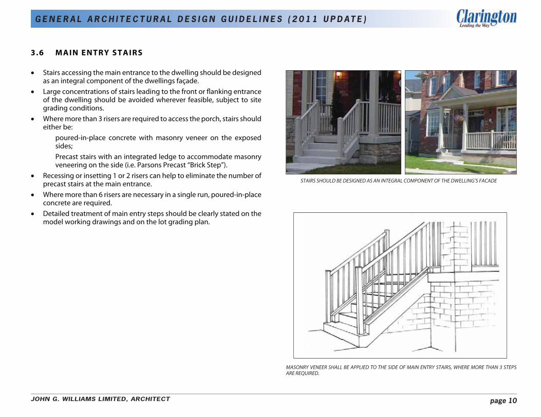
3.6 MAIN ENTRY STAIRS
• Stairs accessing the main entrance to the dwelling should be designed as an integral component of the dwellings façade.
• Large concentrations of stairs leading to the front or flanking entrance of the dwelling should be avoided wherever feasible, subject to site grading conditions.
• Where more than 3 risers are required to access the porch, stairs should either be:
poured-in-place concrete with masonry veneer on the exposed sides; Precast stairs with an integrated ledge to accommodate masonry veneering on the side (i.e. Parsons Precast “Brick Step”).
• Recessing or insetting 1 or 2 risers can help to eliminate the number of STAIRS SHOULD BE DESIGNED AS AN INTEGRAL COMPONENT OF THE DWELLING’S FACADEprecast stairs at the main entrance.
• Where more than 6 risers are necessary in a single run, poured-in-place concrete are required.
• Detailed treatment of main entry steps should be clearly stated on the model working drawings and on the lot grading plan.
MASONRY VENEER SHALL BE APPLIED TO THE SIDE OF MAIN ENTRY STAIRS, WHERE MORE THAN 3 STEPS ARE REQUIRED.
JOHN G. WILLIAMS LIMITED, ARCHITECT page 10

G E N E R A L A R C H I T E C T U R A L D E S I G N G U I D E L I N E S ( 2 0 1 1 U P D AT E )
3.7 R O O F S
Roofs play a significant role in the massing of a dwelling and the overall built form of a residential development. Roofs shall display the following design criteria: • A variety of traditional roof types and forms are encouraged, particularly
for alternate elevations of a model. • Within the design of a streetscape, attention should be paid to the
relationships of adjacent roof forms to ensure appropriate transitions. • Flat main roofs are not permitted, unless a component of a mansard
roof. • 2-storey dwellings shall have a main roof pitch of:
front and rear facing slopes: 5.9:12 minimum; side slopes in profile to the street: 7.9:12 minimum;
• Bungalows shall have a main roof pitch of 7.9:12 min. (both front to back and on sides) to assist in massing compatibility with 2-storey dwellings.
• Side-gabled roofs and roof dormers are also encouraged for bungalows to assist in massing compatibility with 2-storey dwellings.
• Steeper pitches than the minimums stated are encouraged and expected, particularly on side slopes to ensure roof form variety within the streetscape.
• Lower roof slopes may be considered where authentic to the dwelling style (i.e. Arts & Crafts, Prairie Georgian and higher density built forms). The use of lower roof slopes will be at the discretion of the Control Architect on an individual basis and will be dependant upon the architectural style of the dwelling.
• All roofs shall have a 150mm-300mm (6”-12”) overhang. • Where possible, gables within the main roof should have pitches
steeper than the main roof pitch. • All vent stacks, gas flues and roof vents should be located on the rear
slope of the roof wherever possible and should be prefinished to match the roof colour.
• The preferred location of skylights, if proposed, is on the rear or side slope of the roof. Also, they should have a flat profile.
• Roof design should take into consideration the ability to allow for solar panels. In this regard, the overuse of dormers and gables should be avoided in order to provide opportunities for solar panel placement (refer to Section 7.0).
VARIETY OF ROOF FORMS HELPS CREATE VISUAL INTEREST IN THE STREETSCAPE EXAMPLES OF MINIMUM ROOF PITCH
JOHN G. WILLIAMS LIMITED, ARCHITECT page 11
G E N E R A L A R C H I T E C T U R A L D E S I G N G U I D E L I N E S ( 2 0 1 1 U P D AT E )
3.8 WINDOWS
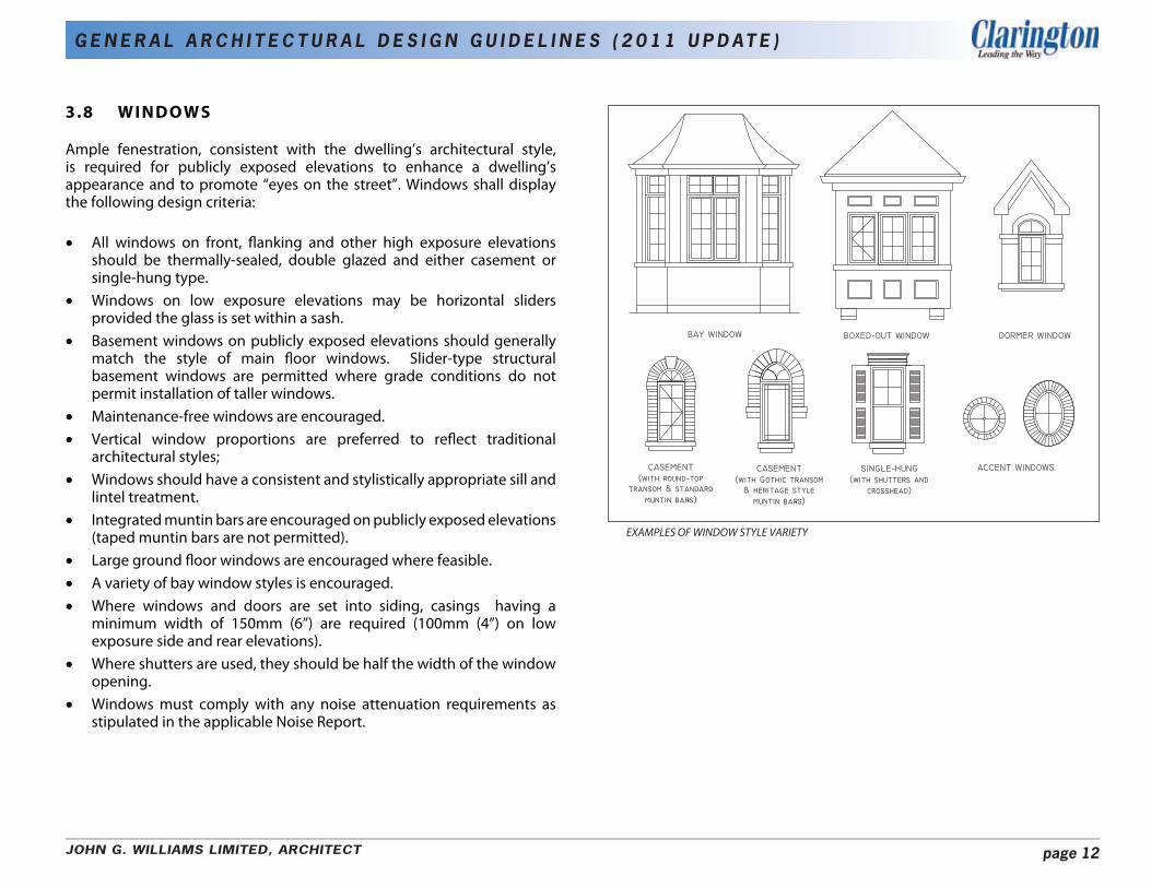
Ample fenestration, consistent with the dwelling’s architectural style, is required for publicly exposed elevations to enhance a dwelling’s appearance and to promote “eyes on the street”. Windows shall display the following design criteria:
• All windows on front, flanking and other high exposure elevations should be thermally-sealed, double glazed and either casement or single-hung type.
• Windows on low exposure elevations may be horizontal sliders provided the glass is set within a sash.
• Basement windows on publicly exposed elevations should generally match the style of main floor windows. Slider-type structural basement windows are permitted where grade conditions do not permit installation of taller windows.
• Maintenance-free windows are encouraged. • Vertical window proportions are preferred to reflect traditional
architectural styles; • Windows should have a consistent and stylistically appropriate sill and
lintel treatment. • Integrated muntin bars are encouraged on publicly exposed elevations
(taped muntin bars are not permitted). • Large ground floor windows are encouraged where feasible. • A variety of bay window styles is encouraged. • Where windows and doors are set into siding, casings having a
minimum width of 150mm (6”) are required (100mm (4”) on low exposure side and rear elevations).
• Where shutters are used, they should be half the width of the window opening.
• Windows must comply with any noise attenuation requirements as stipulated in the applicable Noise Report.
EXAMPLES OF WINDOW STYLE VARIETY
JOHN G. WILLIAMS LIMITED, ARCHITECT page 12

G E N E R A L A R C H I T E C T U R A L D E S I G N G U I D E L I N E S ( 2 0 1 1 U P D AT E )
3.9 WALL CLADDING
A high standard of design, detail and variety of main wall cladding materials should be employed to achieve a cohesive mixture of texture and colour within the streetscape, including: • Brick (clay or calcite) • Stone (natural or manufactured) • Siding (vinyl or pre-finished composite wood in clapboard or board +
batten profiles) • Stucco
i) General Requirements For Wall Cladding
The following general requirements for wall cladding will apply: • The choice of exterior cladding material should be compatible with the
architectural style of the house. • Main wall cladding is encouraged to be consistent on all elevations of
the house to avoid the effect of a false façade. • Wall cladding materials must comply with any noise attenuation
requirements as stipulated in the applicable Noise Report. • Where changes in materials do occur they should happen at logical
locations such as a change in plane, wall opening, downspout or corner detail that will be reviewed on design merit.
• The front façade material should return a minimum of 1200mm (4’-0”) along the side of the house.
• Material changes which help to articulate the transition between the base, middle and top of the building are appropriate.
• The use of secondary materials which blend harmoniously with the primary cladding material are encouraged.
• When siding is used as a secondary material on any elevation of the house it shall be framed with minimum 150mm (6”) aluminum clad trim boards on the top, bottom, sides, corners and at all openings (i.e. windows, doors, etc.). Trim boards should be accentuated by using a contrasting but compatible colour to that of the siding colour.
• Gateway/Primary Corner Dwellings and Primary Street Dwellings should generally incorporate a masonry component. Use of all-siding dwellings in these locations may be considered on their design merits.
• Chimneys located on an exterior wall should be clad with the main wall material.
STUCCOBRICK
STONE SIDING
JOHN G. WILLIAMS LIMITED, ARCHITECT page 13
G E N E R A L A R C H I T E C T U R A L D E S I G N G U I D E L I N E S ( 2 0 1 1 U P D AT E )
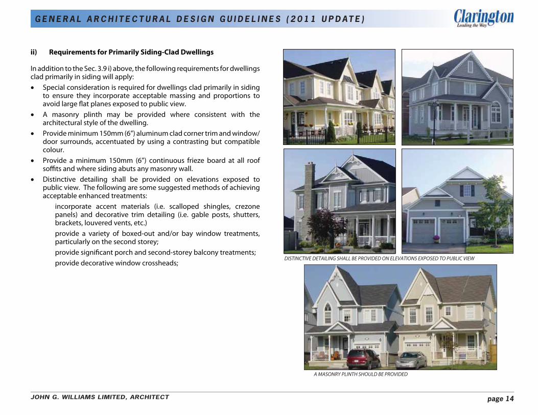
ii) Requirements for Primarily Siding-Clad Dwellings
In addition to the Sec. 3.9 i) above, the following requirements for dwellings clad primarily in siding will apply: • Special consideration is required for dwellings clad primarily in siding
to ensure they incorporate acceptable massing and proportions to avoid large flat planes exposed to public view.
• A masonry plinth may be provided where consistent with the architectural style of the dwelling.
• Provide minimum 150mm (6”) aluminum clad corner trim and window/ door surrounds, accentuated by using a contrasting but compatible colour.
• Provide a minimum 150mm (6”) continuous frieze board at all roof soffits and where siding abuts any masonry wall.
• Distinctive detailing shall be provided on elevations exposed to public view. The following are some suggested methods of achieving acceptable enhanced treatments:
incorporate accent materials (i.e. scalloped shingles, crezone panels) and decorative trim detailing (i.e. gable posts, shutters, brackets, louvered vents, etc.) provide a variety of boxed-out and/or bay window treatments, particularly on the second storey; provide significant porch and second-storey balcony treatments; provide decorative window crossheads;
DISTINCTIVE DETAILING SHALL BE PROVIDED ON ELEVATIONS EXPOSED TO PUBLIC VIEW
A MASONRY PLINTH SHOULD BE PROVIDED
JOHN G. WILLIAMS LIMITED, ARCHITECT page 14
G E N E R A L A R C H I T E C T U R A L D E S I G N G U I D E L I N E S ( 2 0 1 1 U P D AT E )
3.10 EXTERIOR COLOURS
A sufficient variety of exterior colour packages shall be offered by each Builder to avoid monotony within the streetscape. It is also important that individual exterior colour packages combine to create a visually harmonious streetscape appearance. In this respect, jarring colour contrasts will be discouraged. Exterior colours shall display the following design criteria:
• Compatible material colours are required within each individual colour package.
• Soffit, eaves, fascia and frieze board should be the same colour within the individual colour package.
• The use of accent brick for quoining, banding, etc. should be used sparingly. Its colour should be subtle and blend harmoniously with the main wall cladding colour.
• Where siding is used, the colour of the corner trim and window/door casings should generally be a different but harmonious colour to that of the main siding colour, usually matching the soffit/eaves/fascia colour);
• All flashing is to be prefinished to complement the roof or adjacent wall cladding colour.
• The roof colour should complement the colour of main wall cladding. The use of lighter shingle colours such as white, light grey, rainbow red or rainbow green should be avoided.
• No two dwellings which have adjacent frontage or flankage, shall have the same main wall cladding colour.
• No more than 3 identical colour packages will permitted within any group of 10 dwellings and these should be separated by at least 3 dwelling units.
• Where identical front elevations are used in any group of 10 dwellings, such units shall have a distinctly different colour package.
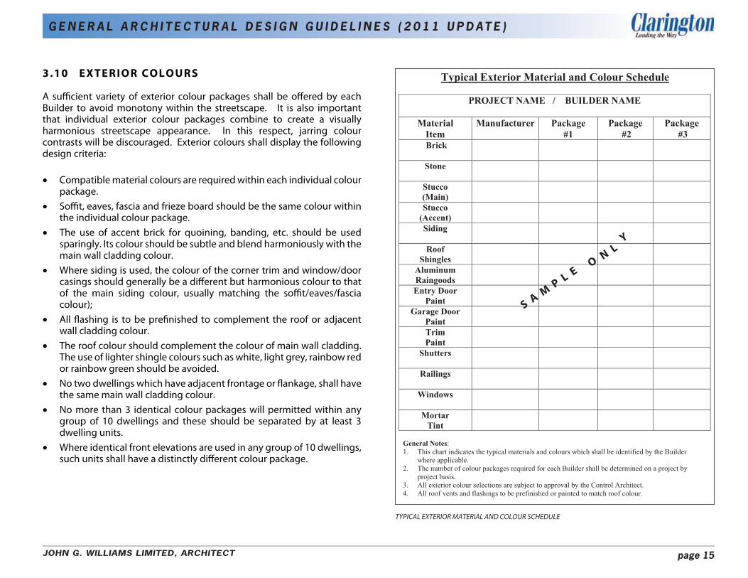
Ty�ical Exterior Material and Colour Schedule
PROJECT NAME I BUI�DER NAME
Material Item
Manufacturer Package #1
Package #�
Package #�
Brick
Stone
Stucco (Main)
Stucco (Accent)
Siding
N LY
Roof Shingles
O
Aluminum Raingoods
S A M
P L
E
Entry Door Paint
Garage Door Paint
Trim Paint
Shutters
Railings
Windows
Mortar Tint
General Notes: 1. This chart indicates the typical materials and colours which shall be identified by the Builder
where applicable. 2. The number of colour packages required for each Builder shall be determined on a project by
project basis. 3. All exterior colour selections are subject to approval by the �ontrol Architect. 4. All roof vents and flashings to be prefinished or painted to match roof colour.
TYPICAL EXTERIOR MATERIAL AND COLOUR SCHEDULE
JOHN G. WILLIAMS LIMITED, ARCHITECT page 15

G E N E R A L A R C H I T E C T U R A L D E S I G N G U I D E L I N E S ( 2 0 1 1 U P D AT E )
3.11 ARCHITECTURAL DETAILING
The use of masonry, painted wood and composite architectural details characteristic to the style of the dwelling help to enhance its appearance. Architectural detailing shall display the following design criteria:
• A variety of trim detailing is encouraged where architecturally appropriate, including:
bargeboard, gable posts, louvers, brackets, dentils, pilasters, scalloped shingles, etc.
• A variety of brick detailing is encouraged where architecturally appropriate, including:
quoining, window/door headers, pilasters, banding, soldier coursing, base corbelling, etc.
• A variety of precast stone detailing is encouraged where architecturally appropriate, including:
keystones, sills, accents, imposts, etc. • All masonry detailing should be accentuated by projecting about
12mm (1/2”) from the wall face. • A frieze board (or brick soldier course cornice) is required on all
exposed elevations and should run along the entire courtyard side of any projecting garage returning a minimum of 1200mm (4’-0”) along elevations facing the interior sideyard.
• Siding and stucco clad dwellings shall always provide trim around door and window openings and include a continuous 150mm (6”) frieze board detail under soffits.
• Where masonry banding is used on the front elevation it shall return a minimum of 1200mm (4’-0”) along elevations facing the interior sideyard.
FRIEZE BOARD UNDER SOFFIT WINDOW SURROUNDS
GABLE POST BRICK HEADERS
BRICK SOLDIER COURSING BRICK QUOINING
JOHN G. WILLIAMS LIMITED, ARCHITECT page 16
G E N E R A L A R C H I T E C T U R A L D E S I G N G U I D E L I N E S ( 2 0 1 1 U P D AT E )
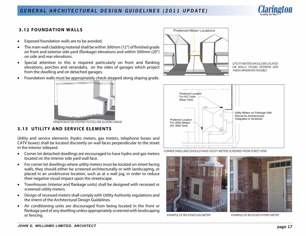
3 .12 FOUNDATION WALLS
• Exposed foundation walls are to be avoided. • The main wall cladding material shall be within 300mm (12”) of finished grade
on front and exterior side yard (flankage) elevations and within 500mm (20”) on side and rear elevations.
• Special attention to this is required particularly on front and flanking elevations, porches and verandahs, on the sides of garages which project from the dwelling and on detached garages.
• Foundation walls must be appropriately check-stepped along sloping grade.
3.13 UTILITY AND SERVICE ELEMENTS
Utility and service elements (hydro meters, gas meters, telephone boxes and CATV boxes) shall be located discreetly on wall faces perpendicular to the street in the interior sideyard.
VENEER MUST BE STEPPED TO FOLLOW SLOPING GRADE
CORNER DWELLINGS SHOULD HAVE UTILITY METERS SCREENED FROM STREET VIEW
Preferred Meter Locations
Preferred Location For Utility Meters
For ��� Units Preferred Location
Utility Meters on Flanka�e �all
Inte�rated or Screened SPo�ld Ie �rcPitect�rally
(�ear Yard)
(Int. Side Yard)
UTILITY METERS SHOULD BE LOCATED ON WALLS FACING INTERIOR SIDE YARDS WHEREVER FEASIBLE
• Corner lot detached dwellings are encouraged to have hydro and gas meters located on the interior side yard wall face.
• For corner lot dwellings where utility meters must be located on street facing walls, they should either be screened architecturally or with landscaping, or placed in an unobtrusive location, such as at a wall jog, in order to reduce their negative visual impact upon the streetscape.
• Townhouses (interior and flankage units) shall be designed with recessed or screened utility meters.
• Design of recessed meters shall comply with Utility Authority regulations and the intent of the Architectural Design Guidelines.
• Air conditioning units are discouraged from being located in the front or flankage yard of any dwelling unless appropriately screened with landscaping or fencing. EXAMPLE OF RECESSED GAS METER EXAMPLE OF RECESSED HYDRO METER
JOHN G. WILLIAMS LIMITED, ARCHITECT page 17

G E N E R A L A R C H I T E C T U R A L D E S I G N G U I D E L I N E S ( 2 0 1 1 U P D AT E )
3.14 ADVERSE GRADE CONDITIONS
• Where severely sloping grade conditions exist, the Builder shall provide models designed or modified to adapt to sloping sites. This is particularly important for lots having back to front sloping grade conditions (full or partial front walk-out condition) to ensure an appropriate relationship between the dwelling, the garage and the street is maintained.
• Elevated main front entrances and large concentrations of stairs should be reduced, wherever feasible, by:
dispersing the steps over a larger area (i.e. within walkway); turning the steps to face the driveway; incorporating some risers inside the dwelling (i.e. sunken foyer);
• In order to maintain an appropriate scale of the main entrance to the pedestrian, a relationship where the main floor is within approximately 1.0m of finished grade is preferred, wherever feasible.
• The design of the garage may require modification to limit its massing on steeply sloping lots. This may be achieved by lowering the roof form of the garage and/or enhancing architectural detailing over the garage. Refer to Section 4.5 for further design criteria related to impact of adverse grade conditions upon garages.
• For walk-up dwelling types that locate the first floor substantially above grade (i.e. Brownstones), exterior steps should be limited to a height of approximately 1.5m. Remaining steps should be located internally.
3.15 MUNICIPAL ADDRESS
SIGNAGE • It is critical that the municipal address is legible from the street,
particularly in emergency situations. For this reason the following criteria shall apply:
It shall be located prominently on the front façade of the dwelling or garage. It shall be in a well-lit area. Numbering shall be a minimum of 100mm (4”) tall and in a simple, legible font face.
• Consideration to a themed / coordinated approach to municipal address numbers should be provided by the builders. For example, a similar style throughout the neighbourhood provides a unifying urban design element which helps define neighbourhood character.
EXAMPLES OF MUNICIPAL ADDRESS SIGNAGE
JOHN G. WILLIAMS LIMITED, ARCHITECT page 18

Park, ScPool Open Space, etc.
Fence Yype as Specified Iy tPe �ity
Fence Yype as Specified Iy tPe �ity
G E N E R A L A R C H I T E C T U R A L D E S I G N G U I D E L I N E S ( 2 0 1 1 U P D AT E )
Pri acyFence
Condition Three: Back to Back Corner Lots
Pri acyFence
Condition T o: Backing onto Other Land ses
Pri acyFence
Condition One: Backing onto Side Lot Line of Ad�acent � e��ing
Park, ScPoolOpen Space, etc.
Pri acyFence
CONCEPTUAL LOCATIONS OF CORNER LOT PRIVACY FENCING
FENCE TYPE AS SPECIFIED BY THE MUNICIPALITY
PARK, SCHOOL, OPEN SPACE, ETC.
FENCE TYPE AS SPECIFIED BY THE MUNICIPALITY
PRIVACY FENCE
3.16 CORNER LOT FENCING
• The design of fencing visible from the public realm shall be compatible throughout the community.
• Corner lot fencing shall be provided by the developer/builder for all corner dwellings. The design of this fencing shall be compatible throughout the neighbourhood.
• Corner lot fencing is intended to screen private rear yards otherwise exposed to flanking streets and must be:
designed by the developer’s consulting landscape architect; be no greater that 1.8m in height; unless otherwise specified in a Noise Attenuation Study consistent with the design, materials and details of other community fencing (i.e. Noise Attenuation Fence); in compliance with applicable noise fencing requirements and municipal standards; located on private property; follow the lot line to a point approximately 1500 mm beyond the corner of the dwelling and then return to within 1350 mm of its flanking face to accommodate a gate.
• All fencing shall comply with the Municipality of Clarington fencing requirements and by-laws
JOHN G. WILLIAMS LIMITED, ARCHITECT page 19

G E N E R A L A R C H I T E C T U R A L D E S I G N G U I D E L I N E S ( 2 0 1 1 U P D AT E )
4.0 DESIGN GUIDELINES FOR GARAGES
The automobile plays an important role within modern suburban communities, hence the garage is a necessity for most homeowners. Typically, dwellings on wider frontage lots are proportionately larger than the garage while the reverse is true for homes on smaller lots. It is important for these Guidelines to minimize the visual impact of the car on the streetscape, particularly those with narrower lot frontages.
4.1 GENERAL CRITERIA FOR ATTACHED GARAGES
The following general design criteria for the treatment of attached garages shall apply: • Attached garages should not dominate the massing of the street-facing dwelling facade. In general,
the massing of the garage should be minimized by: Giving the habitable portion of the dwelling a larger and more dominant mass. Integrating the massing of the garage into the main massing of the dwelling. Positioning the main front wall and porch face closer to the street. Limiting the projection of the garage.
• Garages should be complementary in character and quality to the principal dwelling. • Glazing in overhead garage doors is encouraged, particularly doors wider than 2.5m (8’-0”). • Garage doors should be paneled, sectional roll-up types and have a variety of header/lintel treatments
above.
DWELLINGS SHOULD BE DESIGNED TO MINIMIZE THE VISUAL IMPACT OF THE GARAGE
THE STREETSCAPE SHOULD NOT BE DOMINATED BY GARAGES
JOHN G. WILLIAMS LIMITED, ARCHITECT page 20

G E N E R A L A R C H I T E C T U R A L D E S I G N G U I D E L I N E S ( 2 0 1 1 U P D AT E )
• The streetscape should include a variety of garage door styles to avoid monotony and repetition of a single garage door style.
• The use of tandem garages is encouraged, where feasible, to limit the width of the garage yet provide parking and storage opportunities.
• Where the garage projects in front of the ground level wall or porch face, a window in the courtyard side of the garage consistent with the height and style of the front elevation windows, may be required.
BUILDERS ARE ENCOURAGED TO PROVIDE A VARIETY OF GARAGE DOOR STYLES
4.2 GARAGE WIDTH LIMITATIONS
• Garage widths should relate to the width of the lot to ensure a proportional balance between the habitable portion of the dwelling and the garage is achieved. Garage size shall comply with the applicable Municipality of Clarington Zoning By-laws.
• Outlined below are garage width guidelines based on dwelling type and lot frontage. The use of wider garages may be considered in consultation with Municipality staff and Control Architect where wider lot frontages have been provided and where it does not contravene the by-law.
Townhouses and Semi-Detached dwellings (attached above grade) shall be restricted to a single-car garage per unit having a maximum garage door width of 3.1m (10’). Linked Semi-Detached dwellings (attached below grade) and Single Detached dwellings having lot frontages less than 10.0m shall be restricted to a single-car garage per unit having a maximum garage door width of 3.1m (10’). Single Detached dwellings having lot frontages of 10.0m to 11.2m shall be restricted to a garage with an outside width that is a maximum of 40% of the lot width. For lots having frontages of 11.3m or greater 2-Car garages will be permitted. The use of single bay garage doors separated by a pier, rather than a single 5.0m (16’) wide garage door, will be encouraged wherever feasible. For lots having frontages of 18.3m or greater 3-car garages will be permitted. Single-bay garage doors should be used and the front façade of the garage should be stepped (ie: outside bay setback at least 2’-0”).
• The zoning by-law requires single-detached and semi-detached dwellings, regardless of lot size, to have a minimum of 2 outdoor parking spaces per dwelling. Where the width of the driveway exceeds the width of the garage, the driveway should be no greater than 4.6m wide to accommodate 2 vehicles “side-by-side”.
• Where “side by side” parking is used for single-detached and semidetached dwellings with narrow lot frontages, care should be taken in the design of the dwelling to ensure conflict between the parking area and the porch/stairs is minimized.
JOHN G. WILLIAMS LIMITED, ARCHITECT page 21
G E N E R A L A R C H I T E C T U R A L D E S I G N G U I D E L I N E S ( 2 0 1 1 U P D AT E )
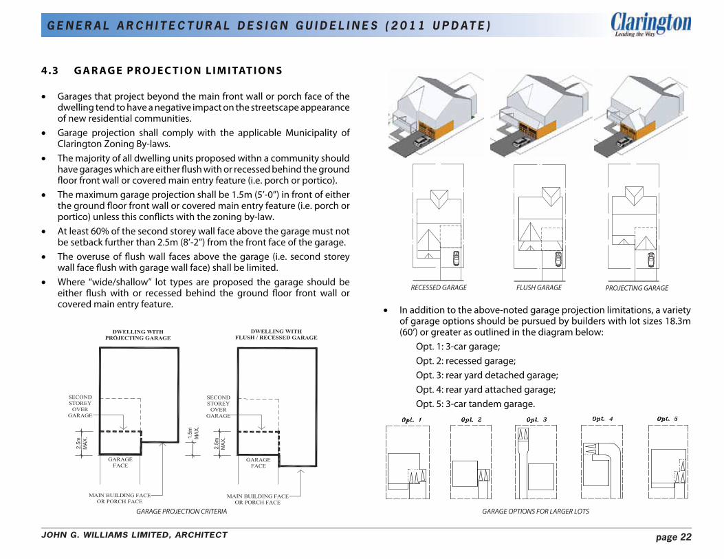
4.3 G A R AG E P R O J E C T I O N L I M I TAT I O N S
• Garages that project beyond the main front wall or porch face of the dwelling tend to have a negative impact on the streetscape appearance of new residential communities.
• Garage projection shall comply with the applicable Municipality of Clarington Zoning By-laws.
• The majority of all dwelling units proposed withn a community should have garages which are either flush with or recessed behind the ground floor front wall or covered main entry feature (i.e. porch or portico).
• The maximum garage projection shall be 1.5m (5’-0”) in front of either the ground floor front wall or covered main entry feature (i.e. porch or portico) unless this conflicts with the zoning by-law.
• At least 60% of the second storey wall face above the garage must not be setback further than 2.5m (8’-2”) from the front face of the garage.
• The overuse of flush wall faces above the garage (i.e. second storey wall face flush with garage wall face) shall be limited.
• Where “wide/shallow” lot types are proposed the garage should be either flush with or recessed behind the ground floor front wall or covered main entry feature.
RECESSED GARAGE FLUSH GARAGE PROJECTING GARAGE
• In addition to the above-noted garage projection limitations, a variety of garage options should be pursued by builders with lot sizes 18.3m (60’) or greater as outlined in the diagram below:
Opt. 1: 3-car garage; Opt. 2: recessed garage; Opt. 3: rear yard detached garage; Opt. 4: rear yard attached garage; Opt. 5: 3-car tandem garage.
GARAGE PROJECTION CRITERIA GARAGE OPTIONS FOR LARGER LOTS
JOHN G. WILLIAMS LIMITED, ARCHITECT page 22

G E N E R A L A R C H I T E C T U R A L D E S I G N G U I D E L I N E S ( 2 0 1 1 U P D AT E )
4.4 TREATMENT OF REAR YARD GARAGES
Rear yard garages that are located in the rear yard and accessed across the front or flanking side yard or from a rear lane are encouraged wherever possible to minimize the visibility of the garage from the street. The following design criteria for rear yard garages shall apply:
• Rear yard garages may be attached or detached from the main dwelling.
• Rear yard garages should be of a complementary design quality, material and colour to the main dwelling.
• The siting of these garages should be as close to the minimum setbacks as possible to maximize the rear yard amenity area.
• The minimum roof pitch for detached garages shall be 5.9:12 with a variety of steeper pitches encouraged.
• Rear yard garages on corner lots or other high exposure lots should be oriented to the minor street and will be of increased design quality consistent with the main dwelling. This will include: additional fenestration; introduction of gables and trim detailing; main wall cladding which is the same as the main dwelling.
• Pairing of garages within the laneway should occur when appropriate. • The municipal address shall be provided on lane-accessed garages in
a well lit location facing the lane. • Garage doors should be sectional roll-up type.
REAR YARD GARAGE ACCESSED FROM LANE
REAR YARD GARAGE ACCESSED FROM LANE REAR YARD GARAGE ACCESSED FROM STREET REAR YARD GARAGE ACCESSED FROM STREET
JOHN G. WILLIAMS LIMITED, ARCHITECT page 23
G E N E R A L A R C H I T E C T U R A L D E S I G N G U I D E L I N E S ( 2 0 1 1 U P D AT E )
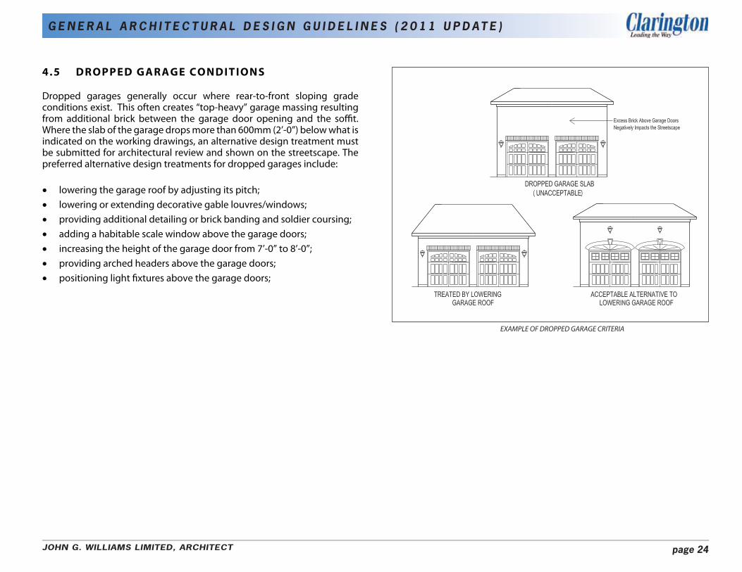
4.5 DROPPED GARAGE CONDITIONS
Dropped garages generally occur where rear-to-front sloping grade conditions exist. This often creates “top-heavy” garage massing resulting from additional brick between the garage door opening and the soffit. Where the slab of the garage drops more than 600mm (2’-0”) below what is indicated on the working drawings, an alternative design treatment must be submitted for architectural review and shown on the streetscape. The preferred alternative design treatments for dropped garages include:
• lowering the garage roof by adjusting its pitch; • lowering or extending decorative gable louvres/windows; • providing additional detailing or brick banding and soldier coursing; • adding a habitable scale window above the garage doors; • increasing the height of the garage door from 7’-0” to 8’-0”; • providing arched headers above the garage doors; • positioning light fixtures above the garage doors;
EXAMPLE OF DROPPED GARAGE CRITERIA
JOHN G. WILLIAMS LIMITED, ARCHITECT page 24
G E N E R A L A R C H I T E C T U R A L D E S I G N G U I D E L I N E S ( 2 0 1 1 U P D AT E )
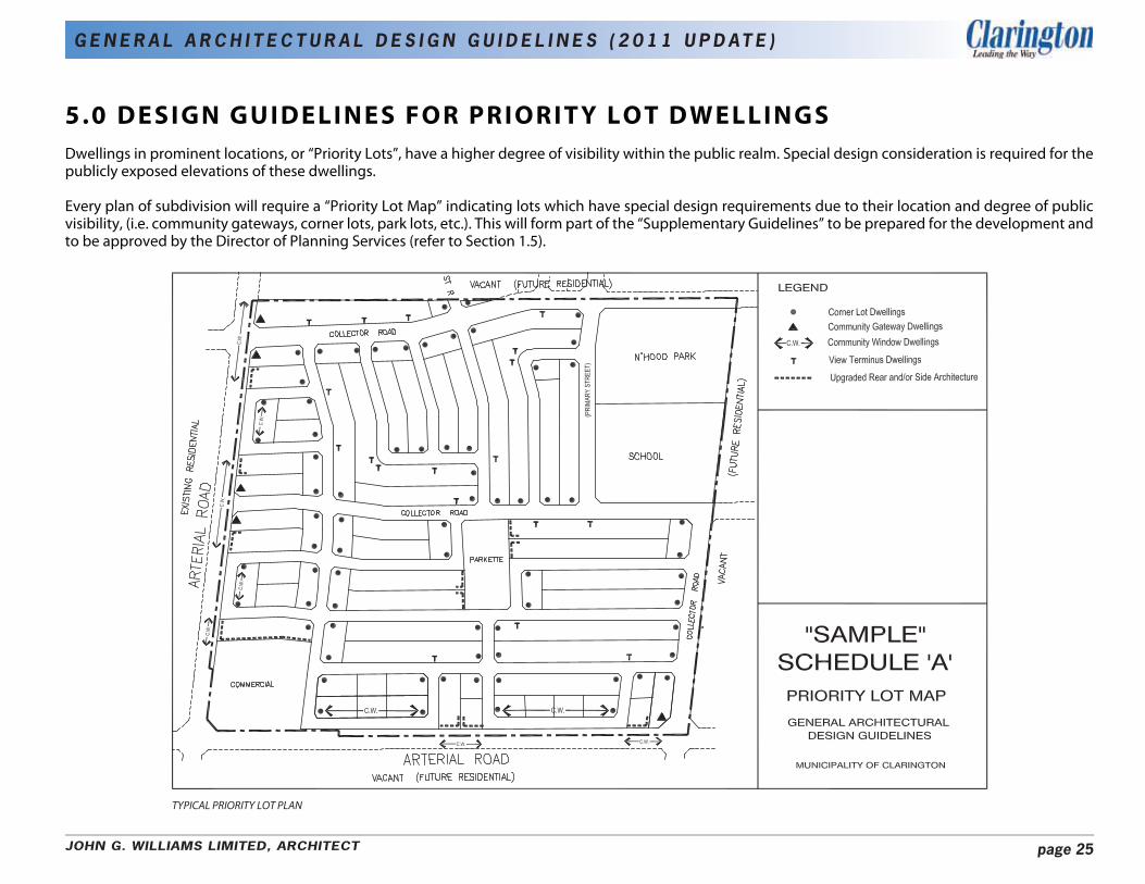
5.0 DESIGN GUIDELINES FOR PRIORITY LOT DWELLINGS
Dwellings in prominent locations, or “Priority Lots”, have a higher degree of visibility within the public realm. Special design consideration is required for the publicly exposed elevations of these dwellings.
Every plan of subdivision will require a “Priority Lot Map” indicating lots which have special design requirements due to their location and degree of public visibility, (i.e. community gateways, corner lots, park lots, etc.). This will form part of the “Supplementary Guidelines” to be prepared for the development and to be approved by the Director of Planning Services (refer to Section 1.5).
TYPICAL PRIORITY LOT PLAN
JOHN G. WILLIAMS LIMITED, ARCHITECT page 25
G E N E R A L A R C H I T E C T U R A L D E S I G N G U I D E L I N E S ( 2 0 1 1 U P D AT E )
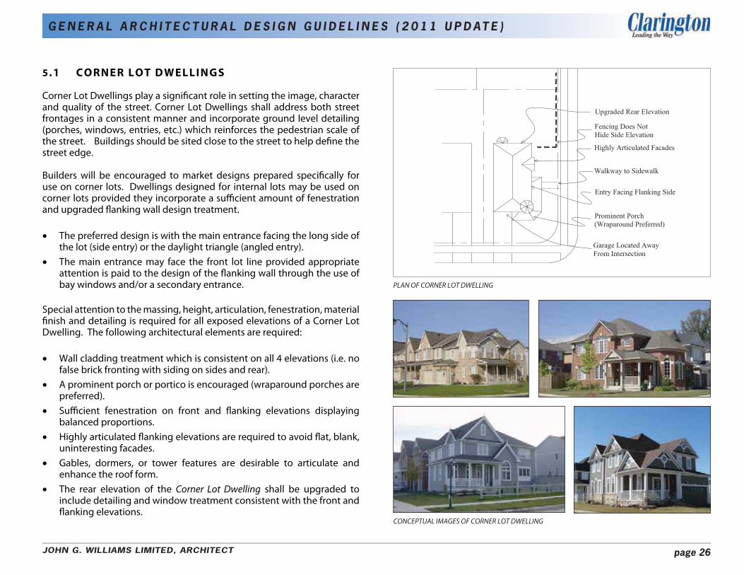
5.1 CORNER LOT DWELLINGS
Corner Lot Dwellings play a significant role in setting the image, character and quality of the street. Corner Lot Dwellings shall address both street frontages in a consistent manner and incorporate ground level detailing (porches, windows, entries, etc.) which reinforces the pedestrian scale of the street. Buildings should be sited close to the street to help define the street edge.
Builders will be encouraged to market designs prepared specifically for use on corner lots. Dwellings designed for internal lots may be used on corner lots provided they incorporate a sufficient amount of fenestration and upgraded flanking wall design treatment.
• The preferred design is with the main entrance facing the long side of the lot (side entry) or the daylight triangle (angled entry).
• The main entrance may face the front lot line provided appropriate attention is paid to the design of the flanking wall through the use of
PLAN OF CORNER LOT DWELLINGbay windows and/or a secondary entrance.
Special attention to the massing, height, articulation, fenestration, material finish and detailing is required for all exposed elevations of a Corner Lot Dwelling. The following architectural elements are required:
• Wall cladding treatment which is consistent on all 4 elevations (i.e. no false brick fronting with siding on sides and rear).
• A prominent porch or portico is encouraged (wraparound porches are preferred).
• Sufficient fenestration on front and flanking elevations displaying balanced proportions.
• Highly articulated flanking elevations are required to avoid flat, blank, uninteresting facades.
• Gables, dormers, or tower features are desirable to articulate and enhance the roof form.
• The rear elevation of the Corner Lot Dwelling shall be upgraded to include detailing and window treatment consistent with the front and flanking elevations.
CONCEPTUAL IMAGES OF CORNER LOT DWELLING
JOHN G. WILLIAMS LIMITED, ARCHITECT page 26
G E N E R A L A R C H I T E C T U R A L D E S I G N G U I D E L I N E S ( 2 0 1 1 U P D AT E )
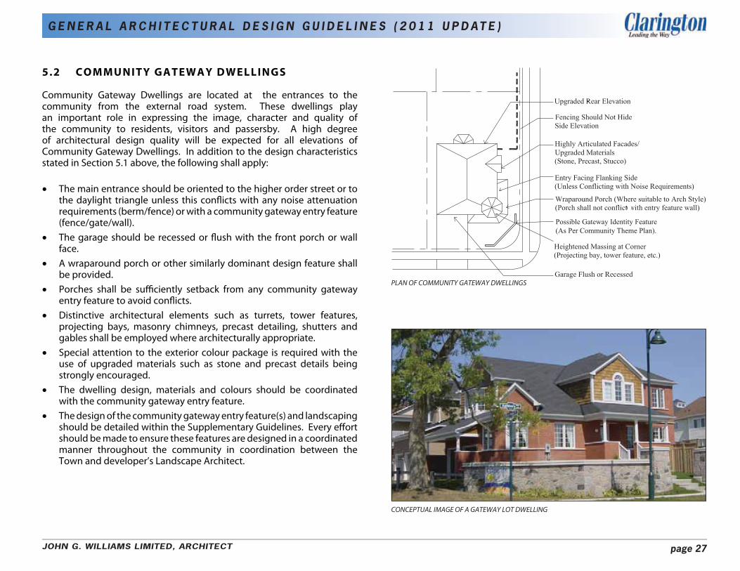
5.2 COMMUNITY GATEWAY DWELLINGS
Community Gateway Dwellings are located at the entrances to the community from the external road system. These dwellings play an important role in expressing the image, character and quality of the community to residents, visitors and passersby. A high degree of architectural design quality will be expected for all elevations of Community Gateway Dwellings. In addition to the design characteristics stated in Section 5.1 above, the following shall apply:
• The main entrance should be oriented to the higher order street or to the daylight triangle unless this conflicts with any noise attenuation requirements (berm/fence) or with a community gateway entry feature (fence/gate/wall).
• The garage should be recessed or flush with the front porch or wall face.
• A wraparound porch or other similarly dominant design feature shall be provided.
• Porches shall be sufficiently setback from any community gateway entry feature to avoid conflicts.
• Distinctive architectural elements such as turrets, tower features, projecting bays, masonry chimneys, precast detailing, shutters and gables shall be employed where architecturally appropriate.
• Special attention to the exterior colour package is required with the use of upgraded materials such as stone and precast details being strongly encouraged.
• The dwelling design, materials and colours should be coordinated with the community gateway entry feature.
• The design of the community gateway entry feature(s) and landscaping should be detailed within the Supplementary Guidelines. Every effort should be made to ensure these features are designed in a coordinated manner throughout the community in coordination between the Town and developer’s Landscape Architect.
Possible �ateway �dentity �eature (As Per �ommunity Theme Plan�.
PLAN OF COMMUNITY GATEWAY DWELLINGS
CONCEPTUAL IMAGE OF A GATEWAY LOT DWELLING
JOHN G. WILLIAMS LIMITED, ARCHITECT page 27

G E N E R A L A R C H I T E C T U R A L D E S I G N G U I D E L I N E S ( 2 0 1 1 U P D AT E )
5.3 COMMUNITY WINDOW DWELLINGS
Community Window Dwellings front onto a service road parallel to an arterial/collector road but are separated from it by a boulevard or buffer. Due to the high degree of public visibility of these dwellings which face a major road, the following requirements will apply:
• The majority of houses within the Community Window streetscape should have a covered front porch.
• Dwellings which flank onto an external arterial road, but which are not corner lots, will require side and rear elevation upgrades.
• Dwellings with front projecting garages should be minimized. • Upgraded building designs are encouraged.
5.4 VIEW TERMINUS DWELLINGS
View Terminus Dwellings occur at the top of a ‘T’ intersection, where one road terminates at a right angle to the other and at street elbows. These dwellings play an important role in the streetscape by terminating a long view corridor. Corner lots opposite these dwellings should frame the view from the street. Because of their prominence View Terminus Dwellings should include such enhancement features as:
• Driveways should be located to the outside of a pair of View Terminus Dwellings to increase landscaping opportunities and reduce the prominence of the garage.
• A greater front yard setback from adjacent dwellings is encouraged where lot depth permits.
• Architectural treatments which provide visual interest will be required for View Terminus Dwellings.
PLAN OF COMMUNITY WINDOW DWELLINGS
PLAN OF VIEW TERMINUS DWELLINGS
CONCEPTUAL IMAGE OF COMMUNITY WINDOW DWELLINGS CONCEPTUAL IMAGE OF VIEW TERMINUS DWELLINGS
JOHN G. WILLIAMS LIMITED, ARCHITECT page 28
G E N E R A L A R C H I T E C T U R A L D E S I G N G U I D E L I N E S ( 2 0 1 1 U P D AT E )
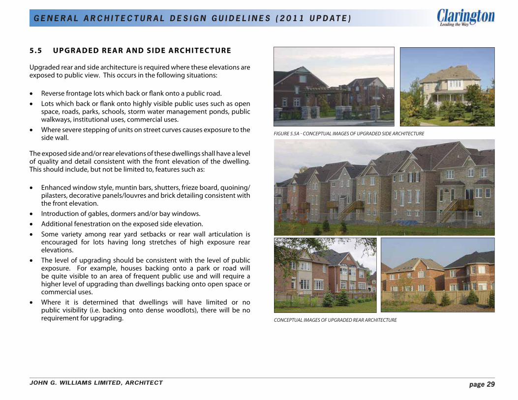
5.5 UPGRADED REAR AND SIDE ARCHITECTURE
Upgraded rear and side architecture is required where these elevations are exposed to public view. This occurs in the following situations:
• Reverse frontage lots which back or flank onto a public road. • Lots which back or flank onto highly visible public uses such as open
space, roads, parks, schools, storm water management ponds, public walkways, institutional uses, commercial uses.
• Where severe stepping of units on street curves causes exposure to the side wall.
The exposed side and/or rear elevations of these dwellings shall have a level of quality and detail consistent with the front elevation of the dwelling. This should include, but not be limited to, features such as:
• Enhanced window style, muntin bars, shutters, frieze board, quoining/ pilasters, decorative panels/louvres and brick detailing consistent with the front elevation.
• Introduction of gables, dormers and/or bay windows. • Additional fenestration on the exposed side elevation. • Some variety among rear yard setbacks or rear wall articulation is
encouraged for lots having long stretches of high exposure rear elevations.
• The level of upgrading should be consistent with the level of public exposure. For example, houses backing onto a park or road will be quite visible to an area of frequent public use and will require a higher level of upgrading than dwellings backing onto open space or commercial uses.
• Where it is determined that dwellings will have limited or no public visibility (i.e. backing onto dense woodlots), there will be no requirement for upgrading.
FIGURE 5.5A - CONCEPTUAL IMAGES OF UPGRADED SIDE ARCHITECTURE
CONCEPTUAL IMAGES OF UPGRADED REAR ARCHITECTURE
JOHN G. WILLIAMS LIMITED, ARCHITECT page 29

G E N E R A L A R C H I T E C T U R A L D E S I G N G U I D E L I N E S ( 2 0 1 1 U P D AT E )
6.0 GUIDELINES FOR SITING OF
DWELLINGS 6.1 BUILDING SETBACK FROM THE STREET LINE
A well-defined, strong street edge helps to reinforce the pedestrian-oriented goals of the community. Well-articulated dwellings with entrances and front porches sited close to the street will be encouraged. The criteria for building setback from the street line are:
• Houses should generally be sited with controlled, orderly setbacks to provide variety, visual interest and a human scale to the street.
• Controlled variety among setbacks from the street line is desirable along long, straight street lengths wherever dwelling designs and lot depths permit. Haphazard stepping of units is to be avoided.
6.2 MODEL REPETITION
Repeating popular models/elevations is acceptable provided it doesn’t conflicts with the requirement for variety within the streetscape. Additional elevations will be required for popular models.
i) Single-Detached and Semi-Detached
The following siting criteria will apply for single-detached and semidetached dwellings :
• The siting of identical elevations side by side or directly opposite is prohibited.
• Identical front elevations of a model shall be separated by a minimum of 2 dwellings (or pairs of semi-detached dwellings) and cannot comprise more than 30% of a street block or be sited greater than 3 times within any row of 10 dwellings. Such elevations must use a different exterior colour package.
• A maximum of 3 distinctly different elevations of the same model (i.e. A, B, C elevations) may be sited side by side.
• Flanking elevations must be different from those flanking elevations on lots abutting or directly opposite.
HOUSES SHOULD BE GENERALLY SITED WITH A CONSISTENT SETBACK TO THE STREET.
WHERE LOT DEPTHS PERMIT, CONTROLLED VARIATION OF SETBACK IS DESIRABLE MODEL REPETITION AND FAÇADE VARIETY CRITERIA (SINGLE DETACHED AND SEMI-DETACHED DWELLINGS)
JOHN G. WILLIAMS LIMITED, ARCHITECT page 30
G E N E R A L A R C H I T E C T U R A L D E S I G N G U I D E L I N E S ( 2 0 1 1 U P D AT E )
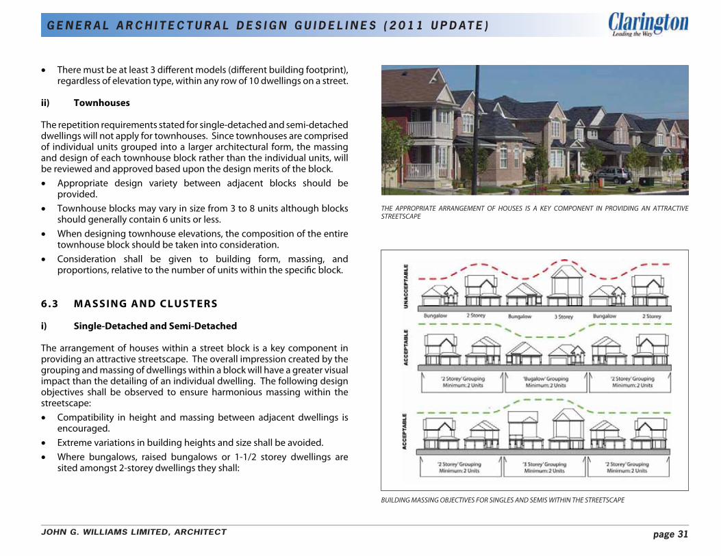
• There must be at least 3 different models (different building footprint), regardless of elevation type, within any row of 10 dwellings on a street.
ii) Townhouses
The repetition requirements stated for single-detached and semi-detached dwellings will not apply for townhouses. Since townhouses are comprised of individual units grouped into a larger architectural form, the massing and design of each townhouse block rather than the individual units, will be reviewed and approved based upon the design merits of the block. • Appropriate design variety between adjacent blocks should be
provided. • Townhouse blocks may vary in size from 3 to 8 units although blocks
should generally contain 6 units or less. • When designing townhouse elevations, the composition of the entire
townhouse block should be taken into consideration. • Consideration shall be given to building form, massing, and
proportions, relative to the number of units within the specific block.
6.3 MASSING AND CLUSTERS
i) Single-Detached and Semi-Detached
The arrangement of houses within a street block is a key component in providing an attractive streetscape. The overall impression created by the grouping and massing of dwellings within a block will have a greater visual impact than the detailing of an individual dwelling. The following design objectives shall be observed to ensure harmonious massing within the streetscape: • Compatibility in height and massing between adjacent dwellings is
encouraged. • Extreme variations in building heights and size shall be avoided. • Where bungalows, raised bungalows or 1-1/2 storey dwellings are
sited amongst 2-storey dwellings they shall:
THE APPROPRIATE ARRANGEMENT OF HOUSES IS A KEY COMPONENT IN PROVIDING AN ATTRACTIVE STREETSCAPE
BUILDING MASSING OBJECTIVES FOR SINGLES AND SEMIS WITHIN THE STREETSCAPE
JOHN G. WILLIAMS LIMITED, ARCHITECT page 31
G E N E R A L A R C H I T E C T U R A L D E S I G N G U I D E L I N E S ( 2 0 1 1 U P D AT E )
comprise groupings of at least 2 adjacent units; employ raised front facades, steeper roof pitches and increased roof massing (side gables/dormers where appropriate) to provide an acceptable transition between these house types.
• Suitably designed single bungalows may be sited on corner lots. • 2-storey dwellings sited amongst bungalows shall comprise groupings
of at least 2 adjacent units. • 3 storey dwellings shall not be sited beside bungalows.
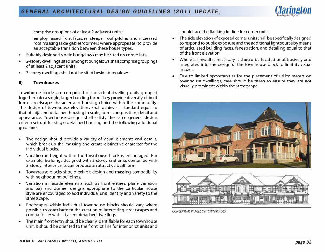
ii) Townhouses
Townhouse blocks are comprised of individual dwelling units grouped together into a single, larger building form. They provide diversity of built form, streetscape character and housing choice within the community. The design of townhouse elevations shall achieve a standard equal to that of adjacent detached housing in scale, form, composition, detail and appearance. Townhouse designs shall satisfy the same general design criteria set out for single detached housing and the following additional guidelines:
• The design should provide a variety of visual elements and details, which break up the massing and create distinctive character for the individual blocks.
• Variation in height within the townhouse block is encouraged. For example, buildings designed with 2-storey end units combined with 3-storey interior units can produce an attractive built form.
• Townhouse blocks should exhibit design and massing compatibility with neighbouring buildings.
• Variation in facade elements such as front entries, plane variation and bay and dormer designs appropriate to the particular house style are encouraged to add individual unit identity and variety to the streetscape.
• Roofscapes within individual townhouse blocks should vary where possible to contribute to the creation of interesting streetscapes and compatibility with adjacent detached dwellings.
• The main front entry should be clearly identifiable for each townhouse unit. It should be oriented to the front lot line for interior lot units and
should face the flanking lot line for corner units. • The side elevation of exposed corner units shall be specifically designed
to respond to public exposure and the additional light source by means of articulated building faces, fenestration, and detailing equal to that of the front elevation.
• Where a firewall is necessary it should be located unobtrusively and integrated into the design of the townhouse block to limit its visual impact.
• Due to limited opportunities for the placement of utility meters on townhouse dwellings, care should be taken to ensure they are not visually prominent within the streetscape.
CONCEPTUAL IMAGES OF TOWNHOUSES
JOHN G. WILLIAMS LIMITED, ARCHITECT page 32
G E N E R A L A R C H I T E C T U R A L D E S I G N G U I D E L I N E S ( 2 0 1 1 U P D AT E )
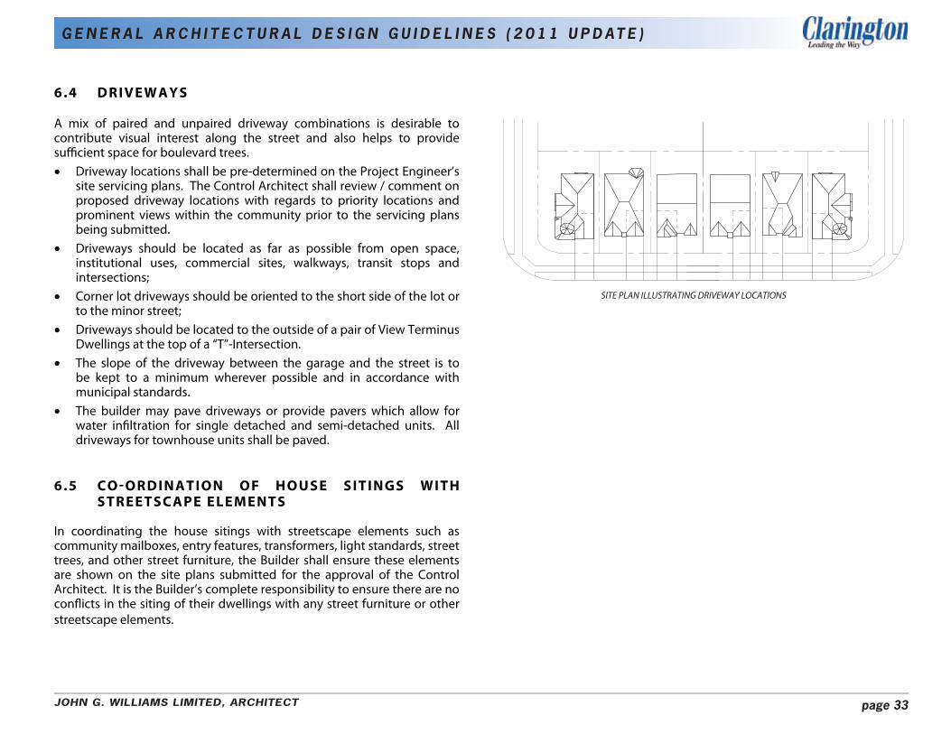
6.4 DRIVEWAYS
A mix of paired and unpaired driveway combinations is desirable to contribute visual interest along the street and also helps to provide sufficient space for boulevard trees. • Driveway locations shall be pre-determined on the Project Engineer’s
site servicing plans. The Control Architect shall review / comment on proposed driveway locations with regards to priority locations and prominent views within the community prior to the servicing plans being submitted.
• Driveways should be located as far as possible from open space, institutional uses, commercial sites, walkways, transit stops and intersections;
• Corner lot driveways should be oriented to the short side of the lot or to the minor street;
• Driveways should be located to the outside of a pair of View Terminus Dwellings at the top of a “T”-Intersection.
• The slope of the driveway between the garage and the street is to be kept to a minimum wherever possible and in accordance with municipal standards.
• The builder may pave driveways or provide pavers which allow for water infiltration for single detached and semi-detached units. All driveways for townhouse units shall be paved.
6.5 CO-ORDINATION OF HOUSE SITINGS WITH STREETSCAPE ELEMENTS
In coordinating the house sitings with streetscape elements such as community mailboxes, entry features, transformers, light standards, street trees, and other street furniture, the Builder shall ensure these elements are shown on the site plans submitted for the approval of the Control Architect. It is the Builder’s complete responsibility to ensure there are no conflicts in the siting of their dwellings with any street furniture or other streetscape elements.
SITE PLAN ILLUSTRATING DRIVEWAY LOCATIONS
JOHN G. WILLIAMS LIMITED, ARCHITECT page 33
G E N E R A L A R C H I T E C T U R A L D E S I G N G U I D E L I N E S ( 2 0 1 1 U P D AT E )
7.0 DESIGN REVIEW AND APPROVAL PROCESS
7.1 PRELIMINARY REVIEW
• Preliminary model design sketches which are in conformity with these Guidelines and which demonstrate sufficient design quality, variety and the use of appropriate exterior materials will be submitted to the control architect for review.
• Exterior building materials and colours will also be submitted at this time.
• Floor plans will have a dashed line with dimensions indicating the second floor wall face where it varies from the first floor wall line.
• Sale of models cannot commence until after preliminary approval is given by the control architect.
• The control architect is to review models with Municipality staff prior to giving final approval.
7.2 FINAL REVIEW AND APPROVAL
i) Working Drawings
• Working drawings must depict exactly what the builder intends to construct.
• All exterior details and materials must be clearly shown on the drawings.
• Special elevations, where required for dwellings on priority lots (upgraded rear and side), walkout lots and grade-affected garage conditions, must be shown on the working drawings.
• A master set of all front, flanking and corner lot rear elevations which have been given final approval is to be submitted to the control architect as soon as possible after model approval is given. This should be on 1 sheet for each dwelling type if possible.
ii) Site Plans
• Engineer certified site plans are to be submitted to the control architect at a minimum scale of 1:250 and may be submitted on single 8-1/2” x 14” sheets.
• In addition to the required grading details, the proposed siting of each unit must clearly show:
model and elevation type; a special note indicating a dropped garage condition (greater than 450m (1’-6”) drop from location approved on working drawings); a special note indicating rear or side upgrades, where applicable.
• Approvals of Site Plans by fax will be permitted.
iii) Streetscape Drawings
To assist in the review process a streetscape drawing (blackline) must accompany each request for siting approval. • Streetscape drawings are to accurately represent the proposed
dwellings in correct relation to each other and to the proposed finished grade.
• In the review of streetscapes, minor elevational changes may be required.
• The onus is on the builder to ensure that these required changes are implemented in the construction of the dwellings.
• Approvals of Streetscapes by fax will be permitted.
iv) Exterior Colour Packages
• Prior to the submission of site plans, the builder will be required to submit typed colour schedules and sample boards which include the colour, type and manufacturer of all exterior materials.
• Colour package selections for individual lots and blocks should be submitted at the same time as site plans and streetscapes.
JOHN G. WILLIAMS LIMITED, ARCHITECT page 34

G E N E R A L A R C H I T E C T U R A L D E S I G N G U I D E L I N E S ( 2 0 1 1 U P D AT E )
7.3 SUBMISSION REQUIREMENTS
• The builder is required to submit to the control architect for final review and approval, the following:
5 sets of engineer approved site/grading plans; 3 sets of working drawings; 3 sets of streetscapes; 2 sets of colour schedules; 1 set of colour sample boards (to be returned to the builder); 1 set of colour board photographs.
• The control architect will retain one set of the foregoing other than the colour sample boards.
• The applicant should allow up to 5 working days for final approvals. • Any minor redline revisions made by the Control Architect to site
plans, working drawings, streetscapes and colour schedules must be incorporated on the originals by the Builder’s design architect.
• Any revisions to an existing approval requested by the Builder will be considered on their merits and if acceptable will be subject to re-approval by the Control Architect.
• It is the Builders’ complete responsibility to ensure that all plans submitted for approval fully comply with these Guidelines and all applicable regulations and requirements including zoning provisions.
• The Builder is responsible for the pick-up and delivery of all materials to and from the Control Architect’s office and the Municipality as necessary.
7.4 R E Q U I R E D A P P R O VA L S
• All site plans, working drawings, streetscapes and colour packages must be submitted for review and approved by the control architect and the project engineer (site plans only), as required, prior to submission to the Municipality of Clarington for building permit approval.
• Building permits will not be issued unless all plans bear the required Final Approval stamp of the control architect and project engineer (site plans only).
• Approvals by the Control Architect and the Project Engineer do not release the builder from complying with the requirements and approvals of the Municipality of Clarington and/or any other governmental agency.
7.5 MONITORING FOR COMPLIANCE
• The Control Architect will conduct periodic drive-by site inspections to monitor development.
• Any visible deficiencies or deviations in construction from the approved plans which are considered by the control architect to be not in compliance with the Architectural Review Guidelines will be reported in writing to the Builder and Municipality.
• The Builder will respond to the control architect in writing within 7 days of notification of their intention to rectify the problem after which the developer and the Municipality will be informed of the Builder’s response or lack of response.
• The developer and/or Municipality may take appropriate action to secure compliance.
JOHN G. WILLIAMS LIMITED, ARCHITECT page 35
G E N E R A L A R C H I T E C T U R A L D E S I G N G U I D E L I N E S ( 2 0 1 1 U P D AT E )
7.6 DISPUTE RESOLUTION
Where there is a dispute between the control architect and the Builder concerning the interpretation or application of these guidelines or the failure to process plans expeditiously, then the following dispute resolution procedure shall apply:
• The aggrieved party shall notify the control architect and Director of Planning Services of the specific reasons and basis for the dispute.
• The control architect shall respond in writing to the Director of Planning Services and the aggrieved party.
• Where the Director of Planning Services feels there is reasonable cause for concern, then the dispute and related correspondence will be referred to an alternate control architect appointed by Developer and acceptable to the Municipality.
• The alternate control architect, whose decision will be final, will promptly review the dispute, make all necessary decisions and advise in writing all parties concerned of the reasons and actions decided upon.
• The fees for the alternate control architect will be paid directly by the builder.
7.7 MONITORING EFFECTIVENESS OF CONTROL ARCHITECT
• Municipality of Clarington staff will also monitor development on a periodic basis to ensure compliance with the Architectural Design Guidelines.
• Should inadequate enforcement by the Control Architect be evident, the Municipality will discuss the situation with the Control Architect.
• If the Municipality is not satisfied with the outcome of the discussions, it may cease to accept drawings stamped by the Control Architect and retain another Control Architect, at the expense of the owner.
• A sufficient notice period of 3-4 weeks will be given by the Municipality to the original Control Architect prior to the transition.
JOHN G. WILLIAMS LIMITED, ARCHITECT page 36