General 3 Series Specifications Coriolis Mass Flow and ...
28
GS 01R4B04-00E-E 3 Series Coriolis Mass Flow and Density Meter GS 01R04B04-00E-E ©Copyright July 2003 (Rü) 10th edition, January 2010 (Rü) Rota Yokogawa GmbH & Co. KG Rheinstr. 8 D-79664 Wehr Germany General Specifications RCCT39/XR RCCT34 - 39/IR RCCF31 + RCCS30 - 33 RCCR31 RCCS34 - 39/IR ROTAMASS is the integral and remote type Coriolis Mass Flowmeter. Both types have highly refined digital signal processing electronics, so that accurate and stable mass flow measurement is achieved. ROTAMASS employs a flame-proof type converter case suitable for use in the hazardous area together with it’s intrinsically safety type detector. ROTAMASS´s signal processing, housing protection and its detector´s special decoupling system against external loads and vibrations, realize high performance in real applications. FEATURES • Field transmitter type mass flowmeter for nearly all fluids, including high viscosity liquids, slurries and multi phase media • Field-mount and rack-mount remote converter available • Refined digital signal processing enables accurate and stable measurement • A special detector decoupling system makes the device highly independent from external loads or vibrations. • Simple flow path means self-draining, food capable and simple to clean • High accuracy and high stability over a wide range • Accurate density measurement, up to +/- 0.0005 g/cm³ • Concentration measurement for solutions, suspensions and emulsions (e.g. water cut, net oil computing) • Two analog outputs, 2 pulse outputs or status-out and one status-in as standard I/O • Available in explosion proof versions (ATEX, FM, IECEx, GOST/RTN, GOST K, INMETRO) • European MID approval for Custody Transfer Measurement acc. OIML R-117-1 (see GS 01R04B07-00E-E) • Wide temperature range –200°C to 350°C • Microprocessor-based multifunction capability • EEPROM protects parameter settings and totalized values during power failure of any duration • High visibly LCD display • HART communication function • Optional Foundation Fieldbus communication (see GS 01R04B05-00E-E) • Optional intrinsically safe outputs • Choice of tube materials • EN, ASME or JIS flanges as standard, others on request PRINCIPLE OF MEASUREMENT Mass flow measurement according to the Coriolis principle. Almost all flowing materials including multi phase fluids, high viscosity liquids (pastes and slurries) and liquid with a certain content of gas. For difficult fluids (e.g. abrasive or highly corrosive fluids) and gases please contact your Yokogawa representative. GS 01R04B04-00E-E Contents Features Page 1 Principle of measurement Page 1 Performance specifications Page 2 Normal operating conditions Page 3 Mechanical specifications Page 4 Electrical specifications Page 5 Remote cable specification Page 5 Hazardous area specifications Page 6 Pressure loss Page 9 Planning and installation hints Page 10 Dimensions Page 12 Model-, suffix- and option- codes Page 18
Transcript of General 3 Series Specifications Coriolis Mass Flow and ...
GS 01R4B04-00E-E
3 SeriesCoriolis Mass Flow and Density Meter
GS 01R04B04-00E-E©Copyright July 2003 (Rü)
10th edition, January 2010 (Rü)
Rota Yokogawa GmbH & Co. KGRheinstr. 8D-79664 WehrGermany
GeneralSpecifications
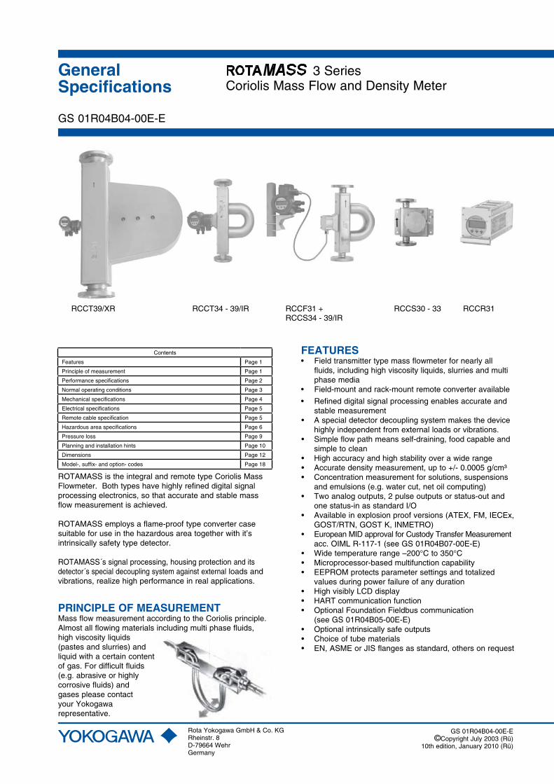
RCCT39/XR RCCT34 - 39/IR RCCF31 + RCCS30 - 33 RCCR31 RCCS34 - 39/IR
ROTAMASS is the integral and remote type Coriolis Mass Flowmeter. Both types have highly refined digital signal processing electronics, so that accurate and stable mass flow measurement is achieved.
ROTAMASS employs a flame-proof type converter case suitable for use in the hazardous area together with it’s intrinsically safety type detector.
ROTAMASS´s signal processing, housing protection and its detector´s special decoupling system against external loads and vibrations, realize high performance in real applications.
FEATURES • Field transmitter type mass flowmeter for nearly all fluids, including high viscosity liquids, slurries and multi phase media• Field-mount and rack-mount remote converter available
• Refined digital signal processing enables accurate and stable measurement• A special detector decoupling system makes the device highly independent from external loads or vibrations.• Simple flow path means self-draining, food capable and simple to clean• High accuracy and high stability over a wide range • Accurate density measurement, up to +/- 0.0005 g/cm³• Concentration measurement for solutions, suspensions and emulsions (e.g. water cut, net oil computing)• Two analog outputs, 2 pulse outputs or status-out and one status-in as standard I/O• Available in explosion proof versions (ATEX, FM, IECEx, GOST/RTN, GOST K, INMETRO)• European MID approval for Custody Transfer Measurement acc. OIML R-117-1 (see GS 01R04B07-00E-E)• Wide temperature range –200°C to 350°C• Microprocessor-based multifunction capability• EEPROM protects parameter settings and totalized values during power failure of any duration• High visibly LCD display• HART communication function• Optional Foundation Fieldbus communication (see GS 01R04B05-00E-E)• Optional intrinsically safe outputs• Choice of tube materials • EN, ASME or JIS flanges as standard, others on request
PRINCIPLE OF MEASUREMENTMass flow measurement according to the Coriolis principle. Almost all flowing materials including multi phase fluids, high viscosity liquids (pastes and slurries) and liquid with a certain contentof gas. For difficult fluids (e.g. abrasive or highly corrosive fluids) and gases please contact your Yokogawa representative.
GS 01R04B04-00E-E
Contents
Features Page 1
Principle of measurement Page 1
Performance specifications Page 2
Normal operating conditions Page 3
Mechanical specifications Page 4
Electrical specifications Page 5
Remote cable specification Page 5
Hazardous area specifications Page 6
Pressure loss Page 9
Planning and installation hints Page 10
Dimensions Page 12
Model-, suffix- and option- codes Page 18

GS 01R04B04-00E-E 10th edition January 21, 2010-00
2
All Rights Reserved. Copyright © 2003, Rota Yokogawa
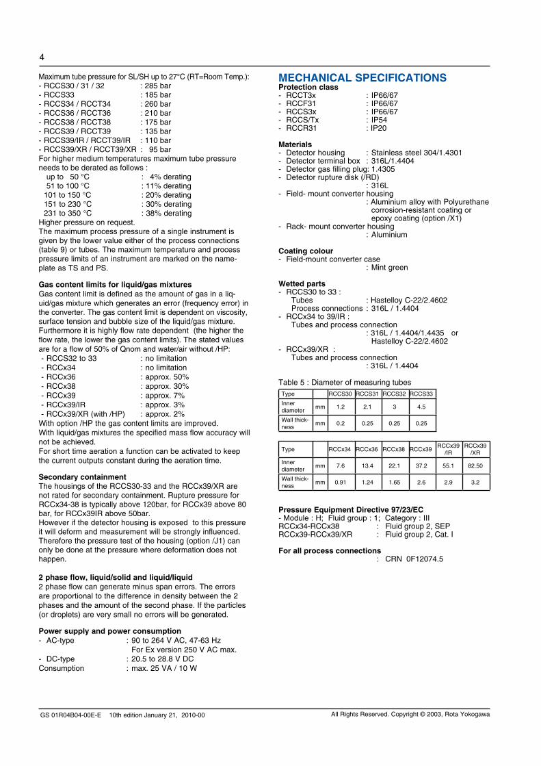
Qnom is the water flow rate at about 1 bar pressure drop.The flowmeter has an automatically low cut at 0.05% of Qnom.
Accuracy mass flow : Liquid : ± 0.1% of flow rate ± zero stability / flow rate *100% (refer to table 2) Gas (option /GA) : ± 0.5% of flow rate ± zero stability / flow rate *100%
(refer to table 2)
Accuracy volume flow : SQRT ( (mass flow error in %)² + (density error in %)²) Please refer to sizing.
Accuracy based on the frequency output includes the combined effects of repeatability, linearity and hysteresis.
Repeatability for liquids: ± 0.05% ± (zero stability/2) / flow rate *100%
Batch process : above specified accuracy if the batch process is >1 minute. For shorter batch time (dt in s) the accuracy decreases with the square root of 60/dt
PERFORMANCE SPECIFICATIONSModel- Remote detector RCCS30 to 33: 2 tubes, low flow design - Remote detector RCCS34 to 39/XR : 2 tube design - Remote field-mount converter RCCF31- Remote rack-mount converter RCCR31- Integral type RCCT34 to 39/XR: 2 tube integral design
Fluid to be measured : Liquid, gas or slurries
Measurement items : Mass flow, density, temperature and derived from these values: concentration, volume flow and net flow
Mass flow measurementTable 1: measuring range
Type RCCS30 RCCS31 RCCS32 RCCS33
Qmax t/h 0.1 0.3 0.6 1.5
Qnom t/h 0.045 0.17 0.37 0.9
Type RCCx34 RCCx36 RCCx38 RCCx39RCCx39
/IRRCCx39
/XR
Qmax t/h 5 17 50 170 300 600
Qnom t/h 2.7 10 32 100 250 500
Table 2 : Zero Stability
Type RCCS30 RCCS31 RCCS32 RCCS33
kg/h 0.005 0.0085 0.019 0.045
Type RCCx34 RCCx36 RCCx38 RCCx39RCCx39
/IRRCCx39
/XR
kg/h 0.135 0.5 1.6 5 13 25
Pressure dependencyThe stiffness of the ROTAMASS tubes is slightly line pressure dependent. The static pressure effect of mass flow and density can be corrected by setting the static pressure manually via menu.Table 3 : Static pressure effect on mass flow (not corrected)
Type RCCS30 RCCS31 RCCS32 RCCS33 RCCx34
% of rate per bar
SS ---- ---- ---- ---- 0.00081
HC 0.00000 0.00012 0.00246 0.02094 0.00084
Type RCCx36 RCCx38 RCCx39RCCx39
/IRRCCx39
/XR
% of rate per bar
SS 0.00346 0.00950 0.01058 0.02920 0.00740
HC 0.00336 0.00896 0.00808 0.01780 ----
Density measurementAdjustment with water and air at calibration temperature.With option /K4 thermal stabilized.For option /K6 see also “Special calibrations” on page 3.Measuring range : 0.3 kg/l to 5 kg/l (RCCx39, RCCx39/IR and RCCx39/XR to 2 kg/l)No density measurement for gas applicationTable 4: Accuracy (at calibration conditions):
Type Standard Option /K4 Option /K6
RCCS30 0.008 g/cm³ ------ ------
RCCS31 0.004 g/cm³ 0.001 g/cm³ ------
RCCS32 0.004 g/cm³ 0.001 g/cm³ 0.0005 g/cm³
RCCS33 0.004 g/cm³ 0.001 g/cm³ 0.0005 g/cm³
RCCx34 0.003 g/cm³ 0.001 g/cm³ 0.0005 g/cm³
RCCx36 0.0022 g/cm³ 0.001 g/cm³ 0.0005 g/cm³
RCCx38 0.0015 g/cm³ 0.001 g/cm³ 0.0005 g/cm³
RCCx39 0.0015 g/cm³ 0.001 g/cm³ 0.0005 g/cm³
RCCx39/IR 0.0015 g/cm³ ------ ------
RCCx39/XR 0.0015 g/cm³ ------ ------
Repeatability: - RCCS32-33, RCCx34-39/XR : ± 0.0005 g/cm³ (Std, /K4)Static pressure effect: Compensated if static pressure is set in the menuInstallation: vertical, else correction term must be set in the softwareSpecification of high performance density measurement (option /K6): Ambient temp. range : -10°C to 50°C Fluid temp. range : -50°C to 150°C Minimum flow rate for specified accuracy: - RCCx36 to RCCx39 : 700 kg/h - RCCx34 : 140 kg/h - RCCS33 : 90 kg/h - RCCS32 : 37 kg/h Maximum flow rate : Qnom Repeatability : ± 0.0002 g/cm³ Temperature measurement: ±0.5°C ±0.2% of reading Density accuracy : ±0.0005 g/cm³ (liquids not aerated / no gas in the liquid) Process temperature influence : 0.000015 g/cm³ * abs(Tfluid-20°C)
-1.0-0.9-0.8-0.7-0.6-0.5-0.4-0.3-0.2-0.1
00.10.20.30.40.50.60.70.80.91.0
0 50 100 150
Flow in % of Qnom
Erro
r in
%
F10.EPS

GS 01R04B04-00E-E 10th edition January 21, 2010-00
3
All Rights Reserved. Copyright © 2003, Rota Yokogawa
Temperature measurement Temperature measuring range of converter :Standard, /LT, /MT : -200°C to 230°COption /HT : 0°C to 350°CAccuracy:Standard (-70°C to 150°C) : ±(0,5°C+0,005*abs(Tmedium-20°C))Option /MT (-70°C to 230°C): ±(0,5°C+0,005*abs(Tmedium-20°C))Option /LT (-200°C to 150°C): ±(1,0°C+0,008*abs(Tmedium-20°C))Option /HT (0°C to 350°C) : ±(1,0°C+0,008*abs(Tmedium-20°C))For process temperatures more than 80°C higher/lower than ambient temperature the detector should be insulated to maintain optimum accuracy.
Heat Tracing Heating with heat carrier, insulation and protection housing. The max. surface temperature at the protection housing from inner heating is 40°C. Above 150°C process temperature insulation from the manufacturer is recommended. However up to 230°C process temperature the customer can insulate the detector themselves.Option /T1 : only insulation and protection Option /T2 : insulation, protection and heating line Option /T3 : like /T2 but with ventilationProcess connection for the heat carrier fluid (see table 10):for D-type flanges : EN DN 15 PN 40 Form B1for A-type flanges : ANSI ½ - 150 lbs.for J-type flanges : JIS DN15 10KMax. pressure : PN 40Protection class : IP54, install roof protectedFor fluid temperatures below -70°C select option /LT and ask for special insulation (see also page 10).
Calibration for liquids and gases :The ROTAMASS flowmeters are always factory calibrated with water. Calibration Conditions: - Water : 22.5°C ± 12.5°C- Ambient temperature : 22.5°C ± 12.5°C- Process Pressure : 1 to 2 bar absFor gas applications please choose option /GA.All specifications are based on above mentioned calibration reference conditions, a flow calibration protocol is attached to each instrument.
Special calibrations - Mass-/Volume flow calibration with factory certificate (option /K2): Calibration with water at customer specified flow values according calibration order sheet.- Mass-/Volume flow calibration with DKD certificate (EN17025: 2005) (option /K5): Calibration with water at customer specified flow values according calibration order sheet.- Density calibration with factory certificate (option /K6) (not with /GA): Adjustment and check with 3 different fluids, fluid temperature influence adjustment for low ambient temperature influence and thermal treatment for long term density measurement stability, enhanced temperature measurement (see also page 11).
Dual Seal approval (option /DS):- Conform with ANSI/ISA-12.27.01.- Only for use with hazardous substances.- Up to ANSI class 900 line pressure.- Only with FM approval option.- For liquid application the leakage detection is realized by software in the converter.- For gas application options /GA and /RD (rupture disk) are mandatory. - Rupture disk is only for annunciation.
NORMAL OPERATING CONDITIONSAmbient temperature limits - Remote detector RCCS3 : Standard : -50°C to +80°C Option /LT : -50°C to +80°C Option /MT : -50°C to +80°C Option /HT : -50°C to +65°C (up to 280°C medium temperature) -50°C to +55°C (up to 350°C medium temperature) terminal box lower 100°C- Remote converter RCCF31, RCCR31 and Integral type RCCT3: Display work. range : -20°C to +55°C Electronic work. range : -40°C to +55°C Cold start : above -30°CWhere meters are mounted in direct sunlight, it is recom-mended to install a sunshade. This is particularly important in countries with high ambient temperatures.
Ambient humidity limits : 0 to 95% R.H.
Process temperature limits
Detector : - RCCS30 to 33 : -50°C to 150°C- RCCS34 to 39/XR : -70°C to 150°C- RCCS34 to 39/XR /MT : -70°C to 230°C (Range 150°C – 230°C recommended with /Tx option)- RCCS34 to 39/XR /LT : -200°C to 150°C - RCCS34 to 39/IR /HT : 0°C to 350°C (only with /Tx option)For use in hazardous area -50°C is low limit.Integral type :- RCCT34 to 39/XR : -50°C to 150°C
Heat carrier fluid temperature limits(option /T2 or /T3 only for remote type RCCS30 to 39/IR)- Standard : 0°C to 150°C- With option /LT : -200°C to 150°C- With option /MT : 0°C to 230°C- With option /HT : 0°C to 350°CFor fluid temperatures below -70°C select option /LT and ask for special insulation (see also page 10).
Process pressure limitsAccording to the flange ratings:- EN PN 16 : max. 16 bar- EN PN 40 : max. 40 bar- EN PN 63 : max. 63 bar- EN PN 100 : max. 100 bar- ASME class 150 : max. 16 bar- ASME class 300 : max. 41 bar- ASME class 600 : max. 83 bar- ASME class 900 : max. 124 bar- ASME class 1500 : max. 207 bar- JIS 10K : max. 14 bar (1.4 MPa)- JIS 20K : max. 34 bar (3.4 MPa)The RCCS30 to RCCS34 have also thread connection. For these connections the max. allowed tube pressure is the limitation. For all other standard process connection please find the max. process pressure in table 9.
GS 01R04B04-00E-E 10th edition January 21, 2010-00
4
All Rights Reserved. Copyright © 2003, Rota Yokogawa
MECHANICAL SPECIFICATIONSProtection class - RCCT3x : IP66/67- RCCF31 : IP66/67- RCCS3x : IP66/67- RCCS/Tx : IP54- RCCR31 : IP20
Materials- Detector housing : Stainless steel 304/1.4301- Detector terminal box : 316L/1.4404 - Detector gas filling plug: 1.4305- Detector rupture disk (/RD) : 316L - Field- mount converter housing : Aluminium alloy with Polyurethane corrosion-resistant coating or epoxy coating (option /X1) - Rack- mount converter housing : Aluminium Coating colour- Field-mount converter case : Mint green
Wetted parts- RCCS30 to 33 : Tubes : Hastelloy C-22/2.4602 Process connections : 316L / 1.4404- RCCx34 to 39/IR : Tubes and process connection : 316L / 1.4404/1.4435 or Hastelloy C-22/2.4602- RCCx39/XR : Tubes and process connection : 316L / 1.4404
Table 5 : Diameter of measuring tubes Type RCCS30 RCCS31 RCCS32 RCCS33
Inner diameter
mm 1.2 2.1 3 4.5
Wall thick-ness
mm 0.2 0.25 0.25 0.25
Type RCCx34 RCCx36 RCCx38 RCCx39RCCx39
/IRRCCx39
/XR
Inner diameter
mm 7.6 13.4 22.1 37.2 55.1 82.50
Wall thick-ness
mm 0.91 1.24 1.65 2.6 2.9 3.2
Pressure Equipment Directive 97/23/EC- Module : H; Fluid group : 1; Category : IIIRCCx34-RCCx38 : Fluid group 2, SEPRCCx39-RCCx39/XR : Fluid group 2, Cat. I
For all process connections : CRN 0F12074.5
Maximum tube pressure for SL/SH up to 27°C (RT=Room Temp.):- RCCS30 / 31 / 32 : 285 bar - RCCS33 : 185 bar- RCCS34 / RCCT34 : 260 bar- RCCS36 / RCCT36 : 210 bar- RCCS38 / RCCT38 : 175 bar- RCCS39 / RCCT39 : 135 bar- RCCS39/IR / RCCT39/IR : 110 bar- RCCS39/XR / RCCT39/XR : 95 barFor higher medium temperatures maximum tube pressure needs to be derated as follows : up to 50 °C : 4% derating 51 to 100 °C : 11% derating 101 to 150 °C : 20% derating 151 to 230 °C : 30% derating 231 to 350 °C : 38% deratingHigher pressure on request.The maximum process pressure of a single instrument is given by the lower value either of the process connections (table 9) or tubes. The maximum temperature and process pressure limits of an instrument are marked on the name-plate as TS and PS.
Gas content limits for liquid/gas mixtures Gas content limit is defined as the amount of gas in a liq-uid/gas mixture which generates an error (frequency error) in the converter. The gas content limit is dependent on viscosity, surface tension and bubble size of the liquid/gas mixture. Furthermore it is highly flow rate dependent (the higher the flow rate, the lower the gas content limits). The stated values are for a flow of 50% of Qnom and water/air without /HP:- RCCS32 to 33 : no limitation- RCCx34 : no limitation- RCCx36 : approx. 50%- RCCx38 : approx. 30%- RCCx39 : approx. 7%- RCCx39/IR : approx. 3%- RCCx39/XR (with /HP) : approx. 2%
With option /HP the gas content limits are improved.With liquid/gas mixtures the specified mass flow accuracy will not be achieved.For short time aeration a function can be activated to keep the current outputs constant during the aeration time.
Secondary containmentThe housings of the RCCS30-33 and the RCCx39/XR are not rated for secondary containment. Rupture pressure for RCCx34-38 is typically above 120bar, for RCCx39 above 80 bar, for RCCx39IR above 50bar.However if the detector housing is exposed to this pressure it will deform and measurement will be strongly influenced. Therefore the pressure test of the housing (option /J1) can only be done at the pressure where deformation does not happen.
2 phase flow, liquid/solid and liquid/liquid2 phase flow can generate minus span errors. The errors are proportional to the difference in density between the 2 phases and the amount of the second phase. If the particles (or droplets) are very small no errors will be generated.
Power supply and power consumption - AC-type : 90 to 264 V AC, 47-63 Hz For Ex version 250 V AC max. - DC-type : 20.5 to 28.8 V DCConsumption : max. 25 VA / 10 W
GS 01R04B04-00E-E 10th edition January 21, 2010-00
5
All Rights Reserved. Copyright © 2003, Rota Yokogawa
Digital communication - HART communication signal, superimposed on 4 -20 mA DC signal (Iout1) - Load resistance : 230 Ω to 600 Ω (including cable) - Power line spacing : >15 cm, avoid parallel wiring - Cable length : ≤ 2 km if „CEV” cables are used- Foundation Fieldbus communication (/FB) - see GS 01R04B05-00E
Setting functions Parameter setting is possible by using the switches on the display or with HART communication.
Display function - Up to 4 lines.- 3 languages selectable (English, German, French)- Instantaneous flow rate, density, temperature or totalized flow can be displayed.
Damping functions Adjustable from 0.1 seconds (63% response time) to 200 seconds, controls display and outputs.
Isolation resistance of converterWhen surge arrestors are removed- between power and ground terminal: 100 MΩ / 500 V DC- between power and I/O terminals : 20 MΩ / 100 V DC- between I/O terminals and ground : 20 MΩ / 100 V DC
Dielectric strengthWhen surge arrestors are removed- between power and ground terminal : 1,500 V AC for 1 minute
Lightning ProtectionArresters (2000 A) are inside converter for power supply lines.
EMCAcc. EN 61326-1: 2006 EN 61326-2-3: 2006 EN 61000-3-2: 2006 EN 61000-3-3: 1995+A1+A2
ELECTRICAL SPECIFICATIONSPower supply - AC- type : 90 V to 264 V 90 V to 250 V for Ex-type- DC- type : 20.5 V to 28.8 V External circuit breaker rating : 5 A, 250 V (In the converter no power switch is installed).
Fuse on Base Board :- AC- type : 2 A, T, breaking capacity 1500A- DC- type : 2 A, T, breaking capacity 1500A
I/O signals- Two active current outputs: 4 to 20 mA DC, galvanic separated from other signals, Load resistance : 20 Ω to 600 Ω Failure current according NAMUR NE43 Ambient temperature effect : < 0.05% of span/10°C Linearity : 0.008 mA = 0.05% of span Setting range URV for liquids: 5 to 100% of Qnom Setting range URV for gases: 1 to 100% of Qnom- Two Pulse outputs / status outputs : Passive Transistor contact output, 30 V DC, 200 mA Output rate : Output 1 : 0 to 10000 pulses/s Output 2 : 0 to 2000 pulses/s Option /NM : passive, according EN 60947-5-6 Option /AP : active output, 12 V, 6 mA, RL> 10 kΩ Active pulse output is not isolated from current output 2 As frequency output : Output 1 : 20 Hz to 10000 Hz Output 2 : 20 Hz to 2000 Hz - Status input : Voltage-free contact Closed : < 200 Ω Open : > 100 kΩ
Option /KF2, /EF2, /UF2: 2 intrinsic safe outputs - One passive current output (additional power supply needed) : 4 to 20 mA DC, galvanic separated from other signals. Supply voltage 10.5 V to 30 V DC (without HART), 165 mA Supply voltage 16.75 V to 30 V DC (with HART), 165 mA Load resistance : 20 Ω ... 600 Ω Ambient temperature effect : < 0.05% of span/10°C- One pulse output / status output : Passive Transistor contact output, 30 V DC, 100 mA Output rate : 0 to 2000 pulses/s As frequency output : 20 Hz to 2000 Hz Option /NM : passive, according EN 60947-5-6- No status input
REMOTE CABLE RCCY03 SPECIFICATIONLi2Y(St)/CY 3x2 AWG24 + 1x3 AWG20 or Li2Y(St)/CY 6x2 AWG24 pair/triple shielded; pair/triple twisted; overall shieldingRCCY033/034 and RCCY031/032/KS1: flame propagation acc. IEC 60332-1.Table 6 : Cable specifications
Model code Temperature range
Wire gauge Resistance of loop
Capacitance wire/wire
Capacitance wire/shield
Inductance wire/wire
RCCY031/032 -50 to +70°CAWG 24AWG 20
190 Ω/km 70 Ω/km
157 nF/km193 nF/km
249 nF/km290 nF/km
0.60 mH/km0.65 mH/km
RCCY031/032 /KS1 -50 to +70°CAWG 24AWG 20
190 Ω/km 70 Ω/km
157 nF/km193 nF/km
249 nF/km290 nF/km
0.60 mH/km0.65 mH/km
RCCY033/034 -30 to +105°CAWG 24AWG 20
177 Ω/km 70 Ω/km
175 nF/km145 nF/km
350 nF/km290 nF/km
0.80 mH/km0.70 mH/km
RCCY033/034 /KS1 -30 to +105°C AWG 24 180 Ω/km 190 nF/km 118 nF/km 0.60 mH/km
GS 01R04B04-00E-E 10th edition January 21, 2010-00
6
All Rights Reserved. Copyright © 2003, Rota Yokogawa
HAzARDOUS AREA SPECIFICATIONSATEX Remote detector RCCS30 ... 39/XR (option /KS1):- KEMA 01ATEX 1075 X- Intrinsically safe- II 2G Ex ib IIB/IIC T1 ... T6- II 2D Ex ibD 21 IP6x Txxx (xxx = max. surface temperature see below)- Max. surface temperature : Standard : 150°C /MT : 220°C /HT : 350°C - Degree of protection : IP67- Ambient humidity : 0 to 95% RH- Ambient temperature range Standard and option /MT : -50°C to +80°C Option /HT (process temperature < 280°C : -50°C to +65°C Option /HT (process temperature < 350°C : -50°C to +55°C- Process temperature limits : Standard : -50°C to 150°C Option /MT: : -50°C to 220°C Option /HT : 0°C to 350°C- Heat carrier fluid temperature limits Standard : -50°C to 150°C Option /MT: : -50°C to 220°C Option /HT : 0°C to 350°C
Remote converter RCCF31 (option /KF1) :- KEMA 02ATEX 2183 X- Flame proof with intrinsic safe connection to detector (ib)- II 2G Ex d(e) [ib] IIC T6- II 2G Ex d(e) [ib] IIB T6 with option /HP- II 2D Ex tD [ibD] A21 IP6x T70°C- Max. surface temperature : 70°C- Degree of protection : IP67- Power supply : 90 to 250 V AC, 50/60 Hz or 20.5 to 28.8 V DC- Power consumption : max. 25 VA / 10 W- Ambient humidity : 0 to 95% RH- Ambient temperature range : -40°C to +50°C
Remote converter RCCF31 (option /KF2) :- KEMA 02ATEX 2183 X- Flame proof with intrinsic safe connection to detector (ib)- Additional intrinsic safe outputs.- II 2G Ex d(e) [ia] [ib] IIC T6- II 2G Ex d(e) [ia] [ib] IIB T6 with option /HP Protection [ia] refers to the intrinsic safe outputs. Protection [ib] refers to the connection to the detector.- II 2D Ex tD [ibD] A21 IP6x T70°C- Max. surface temperature : 70°C- Degree of protection : IP67- Power supply : 90 to 250 V AC, 50/60 Hz or 20.5 to 28.8 V DC- Power consumption : max. 25VA / 10W- Ambient humidity : 0 to 95% RH- Ambient temperature range : -40°C to +50°C
Remote converter RCCR31 (option /KS1) :- KEMA 02ATEX 2183 X- Associated apparatus with intrinsic safe connection to detector (ib)- II (2)G [Ex ib] IIC - II (2)G [Ex ib] IIB with option /HP- II (2)D [Ex ibD] - Power supply : 90 to 250 V AC, 50/60 Hz or 20.5 to 28.8 V DC- Power consumption : max. 25 VA / 10 W- Ambient humidity : 0 to 95% RH- Ambient temperature range : -40°C to +50°C
WARNING Remote rack-mount converter RCCR31 must be installed in safe area !
Integral type RCCT34 ... 39/XR (option /KF1) :- KEMA 02ATEX 2183 X- Flame proof with intrinsic safe connection to detector (ib)- II 2G Ex d(e) [ib] IIC T6 ... T3- II 2G Ex d(e) [ib] IIB T6 ... T3 with option /HP- II 2D Ex tD A21 IP6x T150°C- Max. surface temperature : 150°C- Degree of protection : IP67- Power supply : 90 to 250V AC, 50/60 Hz or 20.5 to 28.8 V DC- Power consumption : max. 25V A / 10 W- Ambient humidity : 0 to 95% RH- Ambient temperature range : -40°C to +50°C
Integral type RCCT34 ... 39/XR (option /KF2) :- KEMA 02ATEX 2183 X- Flame proof with intrinsic safe connection to detector (ib)- Additional intrinsic safe outputs.- II 2G Ex d(e) [ia] [ib] IIC T6 ... T3- II 2G Ex d(e) [ia] [ib] IIB T6 ... T3 with option /HP Protection [ia] refers to the intrinsic safe outputs. Protection [ib] refers to the connection to the detector.- II 2D Ex tD A21 IP6x T150°C- Max. surface temperature : 150°C- Degree of protection : IP67- Power supply : 90 to 250V AC, 50/60 Hz or 20.5 to 28.8V DC- Power consumption : max. 25 VA / 10 W- Ambient humidity : 0 to 95% RH- Ambient temperature range : -40°C to +50°C
Electrical data Remote detector RCCS30 ... 33 :- Driving circuit : terminals D+ and D Ex ib IIC : Ui = 16 V; Ii = 53 mA; Pi = 0.212 W Li = 4.2 mH; Ci = negligible small Ex ib IIB : Ui = 16 V; Ii = 153 mA; Pi = 0.612 W Li = 4.2 mH; Ci = negligible small - Sensor circuits: terminals S1+ and S1- or S2+ and S2- Ex ib IIC : Ui = 16 V; Ii = 80 mA; Pi = 0.32 W Li = 4.2 mH; Ci = negligible small - Temperature sensor circuit : terminals TP1, TP2, TP3 Ex ib IIC : Ui = 16 V; Ii = 50 mA; Pi = 0.2 W Li = negligible small; Ci = negligible small
Electrical data Remote detector RCCS34 ... 39/XR :- Driving circuit : terminals D+ and D Ex ib IIC : Ui = 16 V; Ii = 53 mA; Pi = 0.212 W Li = 3.2 mH; Ci = negligible small Ex ib IIB : Ui = 16 V; Ii = 153 mA; Pi = 0.612 W Li = 3.2 mH; Ci = negligible small - Sensor circuits: terminals S1+ and S1- or S2+ and S2- Ex ib IIC : Ui = 16 V; Ii = 80 mA; Pi = 0.32 W Li = 2.1 mH; Ci = negligible small - Temperature sensor circuit : terminals TP1, TP2, TP3 Ex ib IIC : Ui = 16 V; Ii = 50 mA; Pi = 0.2 W Li = negligible small; Ci = negligible small
Electrical data Remote converter RCCF31, RCCR31 and converter of Intergral type RCCT3 :- Driving circuit : terminals D+ / D- Ex [ib] IIC : Uo = 14.5 V; Io = 47 mA; Po = 0.171 W Lo = 15 mH; Co = 0.65 µF Ex [ib] IIB : Uo = 11.7 V; Io = 124 mA; Po = 0.363 W Lo = 8 mH; Co = 10.3 µF - Sensor circuits: terminals S1+/ S1- or S2+ / S2- Ex [ib] IIB/IIC : Uo = 14.5 V; Io = 47 mA; Po = 0.171 W Ex [ib] IIC : Lo = 15 mH; Co = 0.65 µF Ex [ib] IIB : Lo = 60 mH; Co = 4.07 µF
GS 01R04B04-00E-E 10th edition January 21, 2010-00
7
All Rights Reserved. Copyright © 2003, Rota Yokogawa
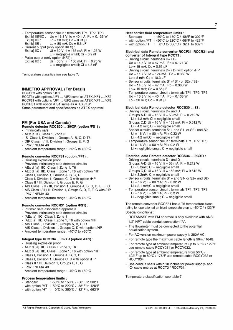
- Temperature sensor circuit : terminals TP1, TP2, TP3 Ex [ib] IIB/IIC : Uo = 13.3 V; Io = 40 mA; Po = 0.133 W Ex [ib] IIC : Lo = 20 mH; Co = 0.91 µF Ex [ib] IIB : Lo = 80 mH; Co = 5.6 µF- Current output (only option /KF2) : Ex [ia] IIC : Ui = 30 V; Ii = 165 mA; Pi = 1.25 W Li = negligible small; Ci = 6.9 nF- Pulse output (only option /KF2) : Ex [ia] IIC : Ui = 30 V; Ii = 100 mA; Pi = 0.75 W Li = negligible small; Ci = 4.5 nF
Temperature classification see table 7.
INMETRO APPROvAL (For Brazil)RCCS3x with option /US1.RCCT3x with options /UF1 ... /UF2 same as ATEX /KF1 ... /KF2RCCF31 with options /UF1 ... /UF2 same as ATEX /KF1 ... /KF2RCCR31 with option /US1 same as ATEX /KS1Same parameters and specifications as ATEX approval.
FM (For USA and Canada)Remote detector RCCS30 ... 39/XR (option /FS1) :- Intrinsically safe- AEx ia IIC, Class 1, Zone 0- IS Class I, Division 1, Groups A, B, C, D T6- DIP Class II / III, Division 1, Groups E, F, G- IP67 / NEMA 4X - Ambient temperature range : -50°C to +80°C
Remote converter RCCF31 (option /FF1) :- Housing explosion proof- Provides intrinsically safe detector circuits- AEx d [ia] IIC, Class I, Zone 1, T6 - AEx d [ia] IIB, Class I, Zone 1, T6 with option /HP- Class I, Division 1, Groups A, B, C, D- Class I, Division 1, Groups C, D with option /HP- Class II / III, Division 1, Groups E, F, G - AIS Class I / II / III, Division 1, Groups A, B, C, D, E, F, G - AIS Class I / II / III, Division 1, Groups C, D, E, F, G with /HP- IP67 / NEMA 4X- Ambient temperature range : -40°C to +50°C
Remote converter RCCR31 (option /FS1) :- Intrinsic safe associated apparatus- Provides intrinsically safe detector circuits- [AEx ia] IIC, Class I, Zone 1- [AEx ia] IIB, Class I, Zone 1, T6 with option /HP- AIS Class I, Division 1, Groups A, B, C, D - AIS Class I, Division 1, Groups C, D with option /HP- Ambient temperature range : -40°C to +50°C
Integral type RCCT34 ... 39/XR (option /FF1) :- Housing explosion proof- AEx d [ia] IIC, Class I, Zone 1, T6 - AEx d [ia] IIB, Class I, Zone 1, T6 with option /HP- Class I, Division 1, Groups A, B, C, D- Class I, Division 1, Groups C, D with option /HP- Class II / III, Division 1, Groups E, F, G - IP67 / NEMA 4X- Ambient temperature range : -40°C to +50°C
Process temperature limits :- Standard : -50°C to 150°C / -58°F to 302°F- with option /MT : -50°C to 220°C / -58°F to 428°F- with option /HT : 0°C to 350°C / 32°F to 662°F
Heat carrier fluid temperature limits :- Standard : -50°C to 150°C / -58°F to 302°F- with option /MT : -50°C to 220°C / -58°F to 428°F- with option /HT : 0°C to 350°C / 32°F to 662°F
Electrical data Remote converter RCCF31, RCCR31 and converter of Intergral type RCCT3 :- Driving circuit : terminals D+ / D- Uo = 14.5 V; Io = 47 mA; Po = 0.171 W Lo = 15 mH; Co = 0.65 µF - Driving circuit : terminals D+ / D- with option /HP Uo = 11.7 V; Io = 124 mA; Po = 0.363 W Lo = 8 mH; Co = 10.3 µF- Sensor circuits: terminals S1+/ S1- or S2+ / S2- Uo = 14.5 V; Io = 47 mA; Po = 0.363 W Lo = 15 mH; Co = 0.65 µF - Temperature sensor circuit : terminals TP1, TP2, TP3 Uo = 13.3 V; Io = 40 mA; Po = 0.133 W Lo = 20 mH; Co = 0.91 µF
Electrical data Remote detector RCCS30 ... 33 :- Driving circuit : terminals D+ and D Groups A-D: Ui = 16 V; Ii = 53 mA; Pi = 0.212 W Li = 4.2 mH; Ci = negligible small Groups C,D: Ui = 16 V; Ii = 153 mA; Pi = 0.612 W Li = 4.2 mH; Ci = negligible small - Sensor circuits: terminals S1+ and S1- or S2+ and S2- Ui = 16 V; Ii = 80 mA; Pi = 0.32 W Li = 4.2 mH;Ci = negligible small - Temperature sensor circuit : terminals TP1, TP2, TP3 Ui = 16 V; Ii = 50 mA; Pi = 0.2 W Li = negligible small; Ci = negligible small
Electrical data Remote detector RCCS34 ... 39/XR :- Driving circuit : terminals D+ and D Groups A-D: Ui = 16 V; Ii = 53 mA; Pi = 0.212 W Li = 3.2mH; Ci = negligible small Groups C,D: Ui = 16 V; Ii = 153 mA; Pi = 0.612 W Li = 3.2mH; Ci = negligible small - Sensor circuits: terminals S1+ and S1- or S2+ and S2- Ui = 16 V; Ii = 80 mA; Pi = 0.32 W Li = 2.1 mH;Ci = negligible small - Temperature sensor circuit : terminals TP1, TP2, TP3 Ui = 16 V; Ii = 50 mA; Pi = 0.2 W Li = negligible small; Ci = negligible small
The remote converter RCCF31 has a T6 temperature class rating for operation at ambient temperature up to +50°C / +122°F.Special conditions :- ROTAMASS with FM approval is only available with ANSI 1/2” NPT cable conduit connection “A”.- The flowmeter must be connected to the potential equalization system.- For AC-version maximum power supply is 250V AC.- For remote type the maximum cable length is 50m / 164ft.- For remote type at ambient temperature up to 50°C / 122°F use remote cable RCCY031 or RCCY032. - For remote type at ambient temperature from 50°C / 122°F up to 80°C / 176°F use remote cable RCCY033 or RCCY034. - Use conduit seals within 18 inches for power supply- and IO- cable entries at RCCT3 / RCCF31.
Temperature classification see table 7.
GS 01R04B04-00E-E 10th edition January 21, 2010-00
8
All Rights Reserved. Copyright © 2003, Rota Yokogawa
GOST APPROvALRota Yokogawa has the “Pattern Approval Certificate of Mea-suring Instruments” which allows to export the instrument to Russia, Kazakhstan, Uzbekistan and other CIS countries. Furthermore ROTAMASS is RTN (GGTN) approved for in-stallation in hazardous areas. For the export of ROTAMASS to CIS countries please contact your Yokogawa representative.
IECEx APPROvALCertificate: IECEx KEM 06.0031X
Remote detector RCCS30 ... 39/XR (option /ES1):- Intrinsically safe- II 2G Ex ib IIB/IIC T6...T1- Standard : Ex ibD 21 IP6x T150°C Option /MT : Ex ibD 21 IP6x T220°C Option /HT : Ex ibD 21 IP6x T350°C - Max. surface temperature : Standard : 150°C /MT : 220°C /HT : 350°C - Degree of protection : IP67- Ambient humidity : 0 to 95% RH- Ambient temperature range Standard and option /MT : -50°C to +80°C Option /HT (process temperature < 280°C : -50°C to +65°C Option /HT (process temperature < 350°C : -50°C to +55°C- Process temperature limits : Standard : -50°C to 150°C Option /MT: : -50°C to 220°C Option /HT : 0°C to 350°C- Heat carrier fluid temperature limits : Standard : -50°C to 150°C Option /MT: : -50°C to 220°C Option /HT : 0°C to 350°C
Remote converter RCCF31 (option /EF1) :- Explosion proof with intrinsic safe connection to detector (ib)- II 2G Ex d(e) [ib] IIC T6- II 2G Ex d(e) [ib] IIB T6 with option /HP- II 2D Ex tD [ibD] A21 IP6x T70°C- Max. surface temperature : 70°C- Degree of protection : IP67- Power supply : 90 to 250 V AC, 50/60 Hz or 20.5 to 28.8 V DC- Power consumption : max. 25 VA / 10 W- Ambient humidity : 0 to 95% RH- Ambient temperature range : -40°C to +50°C
Remote converter RCCF31 (option /EF2) :- Explosion proof with intrinsic safe connection to detector (ib)- Additional intrinsic safe outputs.- II 2G Ex d(e) [ia] [ib] IIC T6- II 2G Ex d(e) [ia] [ib] IIB T6 with option /HP Protection [ia] refers to the intrinsic safe outputs. Protection [ib] refers to the connection to the detector.- II 2D Ex tD [ibD] A21 IP6x T70°C- Max. surface temperature : 70°C- Degree of protection : IP67- Power supply : 90 to 250 V AC, 50/60 Hz or 20.5 to 28.8 V DC- Power consumption : max. 25 VA / 10 W- Ambient humidity : 0 to 95% RH- Ambient temperature range : -40°C to +50°C
Remote converter RCCR31 (option /ES1) :- Associated apparatus with intrinsic safe connection to detector (ib)- II (2)G [Ex ib] IIC - II (2)G [Ex ib] IIB with option /HP- II (2)D [Ex ibD] - Power supply : 90 to 250 V AC, 50/60 Hz or 20.5 to 28.8 V DC- Power consumption : max. 25 VA / 10 W- Ambient humidity : 0 to 95% RH- Ambient temperature range : -40°C to +50°C
WARNING
Remote rack-mount converter RCCR31 must be installed in safe area !
Integral type RCCT34 ... 39/XR (option /EF1) :- Explosion proof with intrinsic safe connection to detector (ib)- II 2G Ex d(e) [ib] IIC T6 ... T3- II 2G Ex d(e) [ib] IIB T6 ... T3 with option /HP- II 2D Ex tD A21 IP6x T150°C- Max. surface temperature : 150°C- Degree of protection : IP67- Power supply : 90 to 250 V AC, 50/60 Hz or 20.5 to 28.8 V DC- Power consumption : max. 25 VA / 10 W- Ambient humidity : 0 to 95% RH- Ambient temperature range : -40°C to +50°C
Integral type RCCT34 ... 39/XR (option /EF2) :- Flame proof with intrinsic safe connection to detector (ib)- Additional intrinsic safe outputs.- II 2G Ex d(e) [ia] [ib] IIC T6 ... T3- II 2G Ex d(e) [ia] [ib] IIB T6 ... T3 with option /HP Protection [ia] refers to the intrinsic safe outputs. Protection [ib] refers to the connection to the detector.- II 2D Ex tD A21 IP6x T150°C- Max. surface temperature : 150°C- Degree of protection : IP67- Power supply : 90 to 250 V AC, 50/60 Hz or 20.5 to 28.8 V DC- Power consumption : max. 25 VA / 10 W- Ambient humidity : 0 to 95% RH- Ambient temperature range : -40°C to +50°C
Electrical data Remote converter RCCF31, RCCR31 and converter of Intergral type RCCT3 :- Driving circuit : terminals D+ / D- Ex [ib] IIC : Uo = 14.5 V; Io = 47 mA; Po = 0.171 W Lo = 15 mH; Co = 0.65 µF Ex [ib] IIB : Uo = 11.7 V; Io = 124 mA; Po = 0.363 W Lo = 8 mH; Co = 10.3 µF - Sensor circuits: terminals S1+/ S1- or S2+ / S2- Ex [ib] IIB/IIC : Uo = 14.5 V; Io = 47 mA; Po = 0.171 W Ex [ib] IIC : Lo = 15 mH; Co = 0.65 µF Ex [ib] IIB : Lo = 60 mH; Co = 4.07 µF- Temperature sensor circuit : terminals TP1, TP2, TP3 Ex [ib] IIB/IIC : Uo = 13.3 V; Io = 40 mA; Po = 0.133 W Ex [ib] IIC : Lo = 20 mH; Co = 0.91 µF Ex [ib] IIB : Lo = 80 mH; Co = 5.6 µF- Current output (only option /EF2) : Ex [ia] IIC : Ui = 30 V; Ii = 165 mA; Pi = 1.25 W Li = negligible small; Ci = 6.9 nF- Pulse output (only option /EF2) : Ex [ia] IIC : Ui = 30 V; Ii = 100 mA; Pi = 0.75 W Li = negligible small; Ci = 4.5 nF
GS 01R04B04-00E-E 10th edition January 21, 2010-00
9
All Rights Reserved. Copyright © 2003, Rota Yokogawa
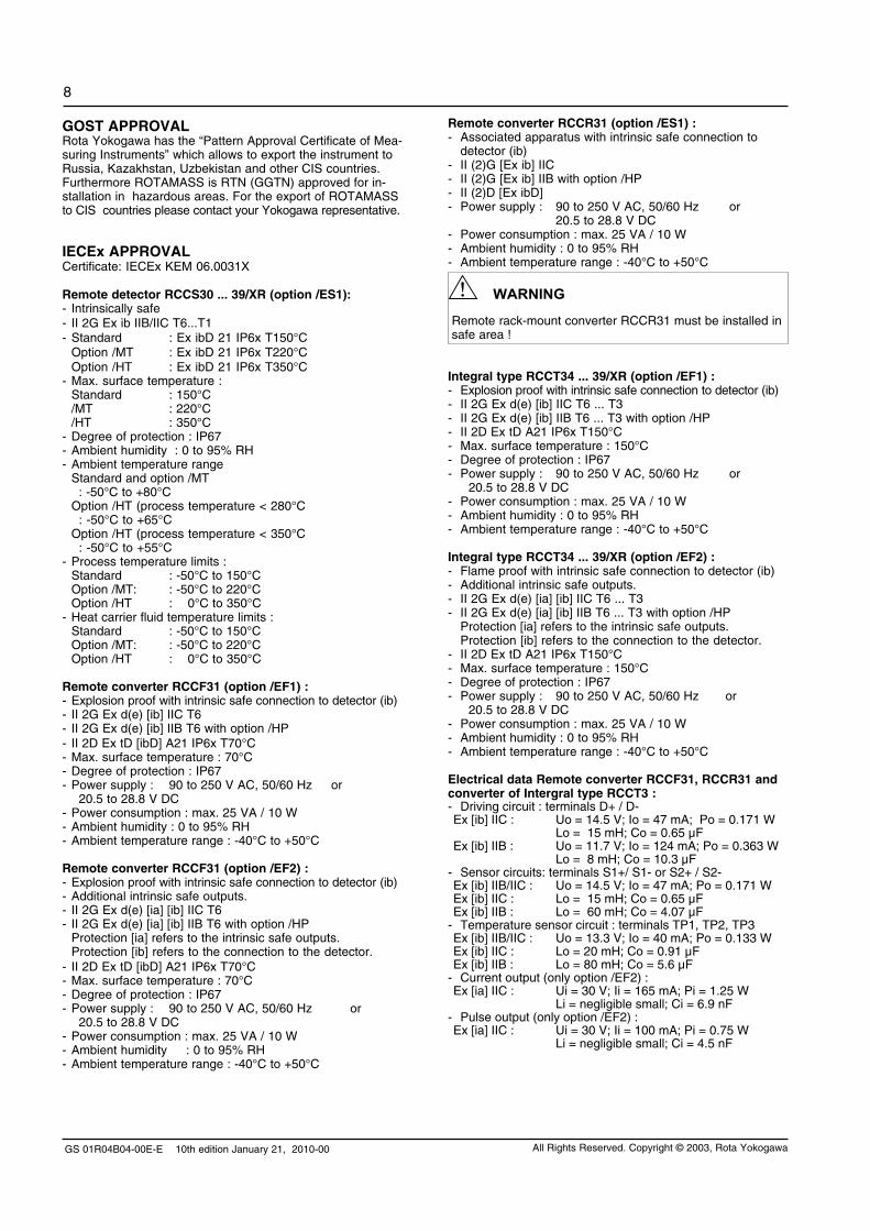
Electrical data Remote detector RCCS30 ... 33:- Driving circuit : terminals D+ / D- Ex ib IIC : Ui = 16 V; Ii = 53 mA; Pi = 0.212 W Li = 4.2 mH; Ci = negligible small Ex ib IIB : Ui = 16 V; Ii = 153 mA; Pi = 0.612 W Li = 4.2 mH; Ci = negligible small - Sensor circuits: terminals S1+/ S1- or S2+ / S2- Ex ib IIC : Ui = 16 V; Ii = 80 mA; Pi = 0.32 W Li = 4.2 mH; Ci = negligible small - Temperature sensor circuit : terminals TP1, TP2, TP3 Ex ib IIC : Ui = 16 V; Ii = 50 mA; Pi = 0.2 W Li = negligible small; Ci = negligible small
Electrical data Remote detector RCCS34 ... 39/XR: - Driving circuit : terminals D+ / D Ex ib IIC : Ui = 16 V; Ii = 53 mA; Pi = 0.212 W Li = 3.2 mH; Ci = negligible small Ex ib IIB : Ui = 16 V; Ii = 153 mA; Pi = 0.612 W Li = 3.2 mH; Ci = negligible small - Sensor circuits: terminals S1+/ S1- or S2+ / S2- Ex ib IIC : Ui = 16 V; Ii = 80 mA; Pi = 0.32 W Li = 2.1 mH; Ci = negligible small - Temperature sensor circuit : terminals TP1, TP2, TP3 Ex ib IIC : Ui = 16 V; Ii = 50 mA; Pi = 0.2 W Li = negligible small; Ci = negligible small
Temperature classification see table 7.
For customer insulation of RCCS30 to 39/XR the following must be regarded :The table "with factory insulation" is calculated with 80 mm insulation and k-factor = 0.4 W/m2K.If your insulation data are worse than these use table "without insulation" !
Table 7 : Temperature classification for ATEX, FM, IECEx and INMETRO certified flowmeter
RCCS30 to RCCS33 without insulation
RCCS30 to RCCS33 with factory insulation
Temp. class Max. ambient temperature
Max. process temperature
Max. ambient temperature
Max. process temperature
T6 50°C / 122°F 60°C / 140°F 60°C / 140°F 60°C / 140°F
T5 50°C / 122°F 80°C / 176°F 80°C / 176°F 90°C / 194°F
T480°C / 176°F50°C / 122°F
100°C / 212°F120°C / 248°F
80°C / 176°F 130°C / 266°F
T3 80°C / 176°F 150°C / 302°F 80°C / 176°F 150°C / 302°F
T2 80°C / 176°F 150°C / 302°F 80°C / 176°F 150°C / 302°F
RCCS34 to RCCS39/XR without insulation
RCCS34 to RCCS39/XR with factory insulation
RCCT34 to RCCT39/XR
Temp. class Max. ambient temperature
Max. process temperature
Max. ambient temperature
Max. process temperature
Max. ambient temperature
Max. process temperature
T6 40°C / 104°F 40°C / 104°F 65°C / 149°F 65°C / 149°F 50°C / 122°F 65°C / 149°F
T5 55°C / 131°F 55°C / 131°F 75°C / 167°F 75°C / 167°F 50°C / 122°F 80°C / 176°F
T480°C / 176°F40°C / 104°F
100°C / 212°F120°C / 248°F
70°C / 158°F 115°C / 239°F 50°C / 122°F 115°C / 239°F
T380°C / 176°F40°C / 104°F
160°C / 320°F180°C / 356°F
70°C / 158°F 180°C / 356°F 50°C / 122°F 150°C / 302°F
T2 80°C / 176°F 220°C / 428°F 65°C /149°F 275°C / 527°F
T1 45°C / 113°F 350°C / 662°F
PRESSURE LOSSPressure loss depends on velocity, viscosity and density of the fluid. For newtonian fluids the pressure loss is shown in table 8 (1 kg/l, 1 mPas). Table 8: Pressure lossType RCCS30 RCCS31 RCCS32 RCCS33
Qmax bar 4.45 2.72 2.34 2.50
Qnom bar 1.11 0.97 1.00 1.01
Type RCCx34 RCCx36 RCCx38 RCCx39RCCx39
/IRRCCx39
/XR
Qmax bar 2.50 3.01 3.58 2.35 1.40 1.42
Qnom bar 0.98 0.95 0.97 0.98 1.00 1.04
NOTE :- For correct pressure loss determination please use the Yokogawa sizing program.- The pressure losses are valid for constant flows. Pulsating flow causes a considerably higher pressure loss on average.

GS 01R04B04-00E-E 10th edition January 21, 2010-00
10
All Rights Reserved. Copyright © 2003, Rota Yokogawa
Heat tracing and insulationBasically the detector can be insulated by the customer. The converter should not be exceeded more than 50°C. Therefore never insulate the converter and keep the neck free from insulation too. To be sure not to overheat the connection box choose one of /Tx options (insulation or heat tracing from Yokogawa). For temperatures between 150°C and 230°C choose /MT option and remote installation. For low temperature fluids ask for special insulation.
Installation above 100°C process temperatureTo provide enough cooling the instrument should be installed vertically or horizontally with the converter down. This is recommended for size RCCT/S36 and larger without /Tx option.
Installation below 0°C process temperatureThe detector can be insulated to prevent ice capping either by the customer or by the manufacturer. Ask your Yokogawa representative for special insulation. If the customer wants to insulate by themselves a closed cell foam as insulation material is recommended to avoid water siphon. In this case option /S2 should be selected. For temperatures below -70°C option /LT is recommended (on request).
zero adjustment functionZero point can be adjusted either by setting the switches on display or with the HART communication or with status input when the fluid is stopped and the detector filled. To ensure no flow conditions isolation valves should be installed. To achieve the specified accuracy a zero should be performed at process conditions (temp., pressure).
Pressure / Temperature dependencies of process connectionsSee also process pressure limits in chapter ”Normal operation conditions”.
Concentration measurement for liquidsThe Standard Concentration Measurement (option /CST) is suitable for concentration measurement of emulsions or suspensions, where the density of the solid is assumed to be fix. It can also be used for (mainly low concentration) solutions if the two fluids are not strongly interacting. The density change of the liquid components due to temperature can normally be described with a linear or quadratic function with very high accuracy within the desired measurement range. The coefficients of these function (linear and quadratic thermal expansion coefficients) must be either known or have to be determined prior to using this function. For interacting liquids the Advanced Concentration Measurement options should be used, these options can be ordered using the appropriate /Cxx concentration measurement option. For more information please see TI 01R04B04-04E-E “Concentration Measurement with ROTAMASS”.
Rupture diskThe rupture disk is used as annunciation method in the case of tube rupture preferable for high pressure gas service. Practically a tube rupture of ROTAMASS is not known to the manufacturer. For large sizes it cannot be expected that the full line pressure can be released via the rupture disk. If this is requested please contact Yokogawa for a special execution.
PLANNING AND INSTALLATION HINTS
Design LimitsIt is the responsibility of the user to use the instrument within the given design limits. Erosion and corrosion influence the accuracy and may restrict the temperature / pressure limits. Therefore corrosion and erosion should be avoided.
Installation The flowmeter can be installed vertically, horizontally or in any other position, as long as the measuring tubes are completely filled with the measured liquid during measurement.
Redundant installationIf two flowmeters of the same size are installed in series mutual interference called cross talk may take place. Cross talk occurs due to the fact that both meters have the same resonance frequency. If serial installation is planned please contact your Yokogawa representative who can ensure that a frequency adjustment is made to one of the meters at the factory.
SizingThe measuring range and accuracy are virtually independent of fluid conditions and size of the connecting pipe. Select a suitable nominal size from pressure loss calculation. Check whether the measuring range and accuracy at minimal flow fit the application. The calculations of the pressure loss are based on Newtonian fluids. For correct calculation of the pres-sure drop use the ROTAMASS Sizing software DUREP V which is part of the Yokogawa Flow Configurator.
Sanitary Applications For sanitary applications select process connection S2, S4 or S8. The wetted surface will be Ra ≤ 1.6µm. However, if op-tion /SFx is selected the surface roughness will be Ra < 0.8µm and with /SF2 a certificate with a 3- point roughness measurement is delivered. The EHEDG certificate shows that ROTAMASS conforms to the EHEDG criteria regarding the capability to be cleaned by a CIP process. The evaluation does not include the process connections and seals.
CavitationTo avoid cavitation keep the back pressure of the fluid suffi-ciently above the vapor pressure of the fluid. For low vis-cous fluids following condition should be fulfilled at the given temperature:
pback > pvapor + 0.7*∆p
With ∆p = pressure loss (e.g. given by the sizing program)
Long Term StabilityTo get stable deflection of the tubes by the coriolis forces the stiffness and therefore the wall thickness has to kept con-stant during measuring. With corrosion or erosion the meter factor is drifting with time and recalibration is necessary. Select the suitable resistant tube material for the process!
Recalibration ServiceYokogawa offers via its European flow centre (Rota Yokogawa, Germany) full recalibration service, if necessary with a certificate traceable to German national standards. Please contact your Yokogawa affiliate or directly Rota Yokogawa, Germany.

GS 01R04B04-00E-E 10th edition January 21, 2010-00
11
All Rights Reserved. Copyright © 2003, Rota Yokogawa
Type of process connection 1)Process Temperature
RT 2) 50°C 100°C 150°C 200°C 250°C 300°C 350°C
A1 Flange acc. ASME B16.5 Class 150 15.9 bar 15.3 bar 13.2 bar 12.0 bar 11.0 bar 10.2 bar 9.7 bar 8.4 bar
A2 Flange acc. ASME B16.5 Class 300 41.4 bar 40.0 bar 34.5 bar 31.2 bar 28.7 bar 26.7 bar 25.2 bar 24.0 bar
A3 Flange acc. ASME B16.5 Class 600 82.7 bar 80.0 bar 69.9 bar 62.8 bar 58.3 bar 54.9 bar 52.1 bar 50.1 bar
A4 Flange acc. ASME B16.5 Class 900 124.1 bar 120.1 bar 104.4 bar 94.2 bar 87.5 bar 82.4 bar 78.2 bar 75.2 bar
A5Flange acc. ASME B16.5 Class 1500
206.8 bar 200.1 bar 173.9 bar 157.0 bar 145.8 bar 137.3 bar 130.3 bar 125.4 bar
D2 Flange acc. EN 1092-1 PN 16 16 bar 15.6 bar 14.2 bar 12.8 bar 11.7 bar 10.9 bar 10.3 bar 9.9 bar
D4 Flange acc. EN 1092-1 PN 40 40 bar 39.1 bar 35.6 bar 32.0 bar 29.3 bar 27.2 bar 25.8 bar 24.7 bar
D5 Flange acc. EN 1092-1 PN 63 63 bar 61.6 bar 56.0 bar 50.4 bar 46.2 bar 42.8 bar 40.6 bar 38.9 bar
D6 Flange acc. EN 1092-1 PN 100 100 bar 97.7 bar 97.7 bar 80.0 bar 73.3 bar 68.0 bar 64.4 bar 61.8 bar
G9 Internal thread (RCCS30...33)See tube pressure, for option /DS max. pressure accord-
ing A4, ASME class 900------------------------------------------------------------------------
T9 Internal thread NPT (RCCS30...33)See tube pressure, for option /DS max. pressure accord-
ing A4, ASME class 900------------------------------------------------------------------------
G9 Internal thread (RCCS34) See tube pressure, for option /DS max. pressure according A4, ASME class 900
T9 Internal thread NPT (RCCS34) See tube pressure, for option /DS max. pressure according A4, ASME class 900
Process Temperature
up to 120°C 220°C 300°C 350°C
J1 Flange acc. JIS B 2220 10K 14 bar 12 bar 10 bar ------
J2 Flange acc. JIS B 2220 20K 34 bar 31 bar 29 bar 26 bar
Process Temperature
up to 140°C *)
S2
Pipe connection up to DN 40
acc. DIN 11851 DN 50 to DN 100
above DN 100
40 bar*) under the restriction using suitable gasket materials25 bar
16 bar
Process Temperature
up to 150°C **)
S4Clamp connection up to DN 50acc. DIN 32676 above DN 50
16 bar
**) under the restriction using suitable gasket materials10 bar
S8Clamp acc. Mini-Clamp up to 1/2´´ 16 bar
Clamp acc. Tri-Clamp up to 2´´ above 2´´
16 bar10 bar
1) all process connections acc. AISI 316L (1.4404 / 1.4435)2) RT = Room Temperature; EN1092: -10°C to 50°C; ASME B16.5: -29°C to 38°C
Explosion proof concept and option /HP The detector is intrinsically safe, the converter flame (explosion) proof (RCCF31) or intrinsically safe associated apparatus (RCCR31). The driving power from converter to detector is limited and protected by a barrier, which is part of the converter. The barrier is protecting the detector either for gas group IIC or IIB (option /HP). With option /HP the detector driving power is higher which is benefit to 2 phase flow. This is also true for non hazardous applications. Option /KF2 delivers one passive intrinsic safe current and one pulse output, however the converter is flame (explosion) proof.
Density measurement We offer 3 levels of density measurement. The standard adjustment (also /K4) delivers an accuracy up to 0.001 g/cm³, if the fluid density is around 1 kg/l. However, at elevated temperatures the density error may increase. For option /K4 the instrument is preheated ensuring long term stability. How-ever, if high density stability is needed at high temperatures option /HT is recommended. Option /K6 includes preheating, a full calibration at 3 different densities, increased tempera-ture measurement specification and individual adjustment of the fluid temperature dependency. For more information please see TI 01R04B04-05E ”Density Measurement with ROTAMASS”.Overview density-/volume flow measurement:
Option Accuracy Certificate Description Application
Standard ± 0.0015 g/cm³ to± 0.008 g/cm³
Standard (mass flow) factory calibration certificate
- Standard adjustment with water and air- Density constants given in mass flow certificate
- Process medium and environment are approximately at room temperature, the density range is 0.9 kg/l to 1.1 kg/l
Option /K4 ± 0.001 g/cm³ Standard (mass flow) factory calibration certificate
- Thermal treatment of the sensor and special hardware design- Standard adjustment with water and air- Density constants given in mass flow certificate
- Improved volume flow accuracy- Process medium up to 150°C, for higher temperature select option /HT- Density range is 0.9 kg/l to 1.1 kg/l
Option /K6 ± 0.0005 g/cm³ Separate factory density calibration certificate
- Thermal treatment of the sensor and special hardware design - Density calibration with 3 different liquids- Individual adjustment of the fluid temperature dependency
- Density and concentration measurement in addition to the mass flow:- Process medium up to 150°C, for higher temperature select option /HT- Density range 0.3 kg/l to 2 kg/l- Best volume flow accuracy
Table 9 : Pressure rating

GS 01R04B04-00E-E 10th edition January 21, 2010-00
12
All Rights Reserved. Copyright © 2003, Rota Yokogawa
Note: The flange dimensions depend on size and pressure rating of the flange.
Model L1 L2 L3 H1 H2 H3 H4 W1 W2 Weight
RCCT34 [mm] see table 11 272 212 180 212 278 80 60 80 13 kg
RCCT36 [mm] see table 11 400 266 233 212 278 80 76 90 17 kg
RCCT38 [mm] see table 11 490 267 274 222 288 100 89 110 26 kg
RCCT39 [mm] see table 11 850 379 370 240 306 135 129 160 64 kg
RCCT39/IR [mm] see table 11 870 455 453 272 338 200 155 200 92 kg
RCCT39/XR [mm] see separate figure on page 15
Dimensions in [mm]. Weights with smallest flanges.
DIMENSIONSIntegral type RCCT34 - 39/IR
GS 01R04B04-00E-E 10th edition January 21, 2010-00
13
All Rights Reserved. Copyright © 2003, Rota Yokogawa
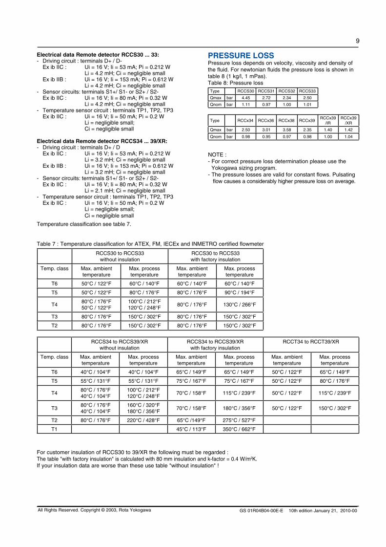
Remote field-mount converter RCCF31
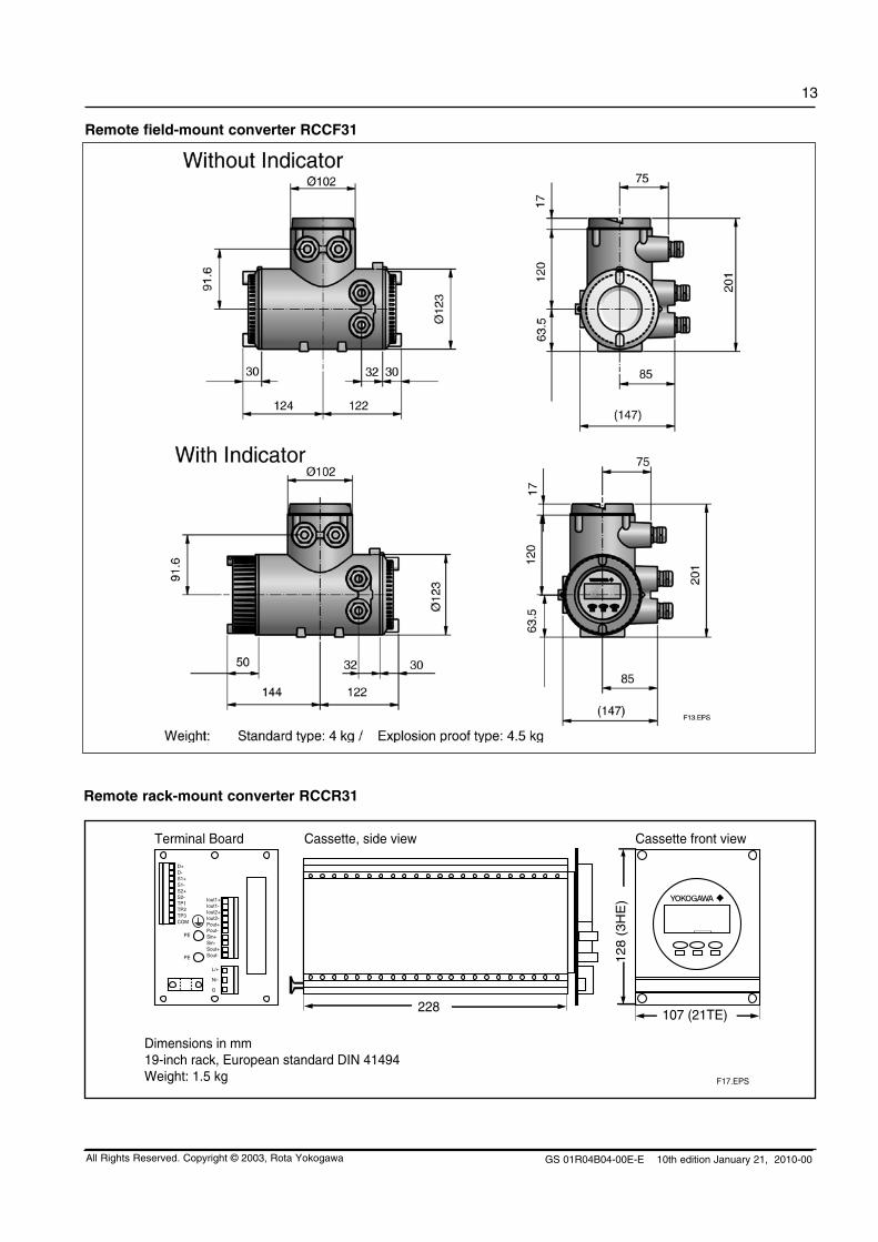
Remote rack-mount converter RCCR31
107 (21TE)
128 (
3H
E)
228
Dimensions in mm19-inch rack, European standard DIN 41494Weight: 1.5 kg
Cassette front viewCassette, side viewTerminal Board
PE
PE
D+D-S1+S1-S2+S2-TP1TP2TP3COM
Iout1+Iout1-Iout2+Iout2-Pout+Pout-Sin+Sin-Sout+Sout-
L/+
N/-
G
F17.EPS
GS 01R04B04-00E-E 10th edition January 21, 2010-00
14
All Rights Reserved. Copyright © 2003, Rota Yokogawa
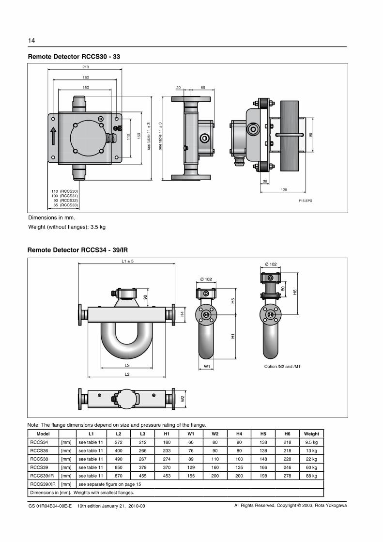
Remote Detector RCCS34 - 39/IR
Remote Detector RCCS30 - 33
see
tabl
e 11
± 3
see
tabl
e 11
± 3
110 (RCCS30)100 (RCCS31) 90 (RCCS32) 65 (RCCS33)
Dimensions in mm.
Weight (without flanges): 3.5 kg
Note: The flange dimensions depend on size and pressure rating of the flange.
Model L1 L2 L3 H1 W1 W2 H4 H5 H6 Weight
RCCS34 [mm] see table 11 272 212 180 60 80 80 138 218 9.5 kg
RCCS36 [mm] see table 11 400 266 233 76 90 80 138 218 13 kg
RCCS38 [mm] see table 11 490 267 274 89 110 100 148 228 22 kg
RCCS39 [mm] see table 11 850 379 370 129 160 135 166 246 60 kg
RCCS39/IR [mm] see table 11 870 455 453 155 200 200 198 278 88 kg
RCCS39/XR [mm] see separate figure on page 15
Dimensions in [mm]. Weights with smallest flanges.
GS 01R04B04-00E-E 10th edition January 21, 2010-00
15
All Rights Reserved. Copyright © 2003, Rota Yokogawa
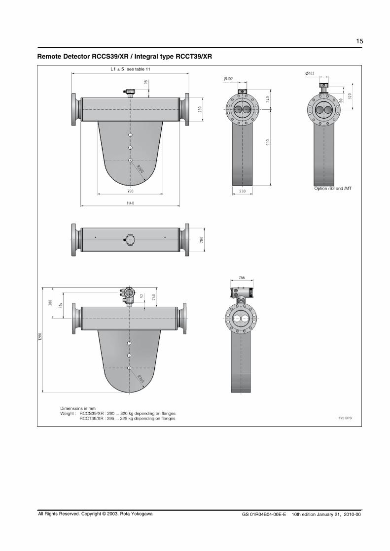
Remote Detector RCCS39/XR / Integral type RCCT39/XR
see table 11
GS 01R04B04-00E-E 10th edition January 21, 2010-00
16
All Rights Reserved. Copyright © 2003, Rota Yokogawa
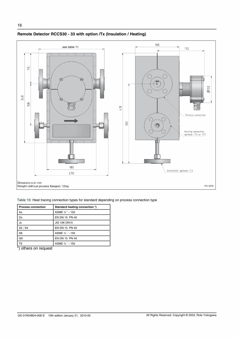
Table 10: Heat tracing connection types for standard depending on process connection type
Process connection Standard heating connection *)
Ax ASME ½´´ - 150
Dx EN DN 15 PN 40
Jx JIS 10K DN15
S2 ; S4 EN DN 15 PN 40
S8 ASME ½´´ - 150
G9 EN DN 15 PN 40
T9 ASME ½´´ - 150
*) others on request
Remote Detector RCCS30 - 33 with option /Tx (Insulation / Heating)
see table 11
GS 01R04B04-00E-E 10th edition January 21, 2010-00
17
All Rights Reserved. Copyright © 2003, Rota Yokogawa
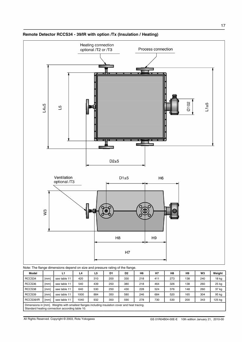
Remote Detector RCCS34 - 39/IR with option /Tx (Insulation / Heating)
Note: The flange dimensions depend on size and pressure rating of the flange.
Model L1 L4 L5 D1 D2 H6 H7 H8 H9 W3 Weight
RCCS34 [mm] see table 11 420 310 200 330 218 411 273 138 240 18 kg
RCCS36 [mm] see table 11 540 439 250 380 218 464 326 138 260 25 kg
RCCS38 [mm] see table 11 640 530 250 430 228 524 376 148 260 37 kg
RCCS39 [mm] see table 11 1000 884 350 580 246 684 520 165 304 95 kg
RCCS39/IR [mm] see table 11 1040 932 350 590 278 730 530 200 343 125 kg
Dimensions in [mm]. Weights with smallest flanges including insulation cover and heat tracing.Standard heating connection according table 10.

GS 01R04B04-00E-E 10th edition January 21, 2010-00
18
All Rights Reserved. Copyright © 2003, Rota Yokogawa
MODEL-, SUFFIX- AND OPTION-CODESIntegral type RCCT3, Model- and Suffix- Code :Model Suffix Code Description Restrictions
RCCT34RCCT36RCCT38RCCT39RCCT39/IRRCCT39/XR
Nominal Value : 2.7 t/h = 45 kg/minNominal Value : 10 t/h = 170 kg/minNominal Value : 32 t/h = 533 kg/minNominal Value : 100 t/h = 1670 kg/minNominal Value : 250 t/h = 4170 kg/minNominal Value : 500 t/h = 8340 kg/min only with /HP
Power supply -A-D
90 - 264 V AC24 V DC
Indicator direction H1H2V0N0
Detector installation horizontal, tubes downDetector installation horizontal, tubes upDetector installation verticalWithout indicator
recom. for liquid servicerecom. for gas service /GA
Cable conduit connection MA
M20 x 1, female thread with cable glandsANSI ½´´ NPT, female thread without cable glands mandatory with /FF1, /FF3
Process connection size 1) 2301020405060810121520
¾´´DN 15, ½´´DN 25, 1´´DN 40, 1½´´DN 50, 2´´DN 65, 2½´´DN 80, 3´´DN 100, 4´´DN 125, 5´´DN 150, 6´´DN 200, 8´´
see table 11see table 11see table 11see table 11see table 11see table 11see table 11see table 11see table 11see table 11see table1
Process connection rating and style 1) A1A2A3A4A5D2D4D5D6J1J2S2S4S8G9T9
ASME flange class 150, process connection dim. + facing acc. ASME B16.5ASME flange class 300, process connection dim. + facing acc. ASME B16.5ASME flange class 600, process connection dim. + facing acc. ASME B16.5ASME flange class 900, process connection dim. + facing acc. ASME B16.5ASME flange class 1500, process connection dim. + facing acc. ASME B16.5EN flange PN 16, process connection dim. + facing acc. EN 1092-1 Form B2EN flange PN 40, process connection dim. + facing acc. EN 1092-1 Form B2EN flange PN 63, process connection dim. + facing acc. EN 1092-1 Form B2EN flange PN 100, process connection dim. + facing acc. EN 1092-1 Form B2JIS flange 10K, JIS B 2220JIS flange 20K, JIS B 2220Thread acc. DIN 11851Clamp, process connection dimensions acc. DIN 32676Clamp, process connection dim. acc. Tri-Clover (Tri-Clamp) and ½´´ Mini ClampG, female threadNPT, female thread
see table 11see table 11see table 11see table 11see table 11see table 11see table 11see table 11see table 11see table 11see table 11see table 11see table 11see table 11see table 11see table 11
Material of wetted parts 1) SLHC
Stainless steel 316L (1.4404)Hastelloy C-22 (2.4602) only RCCT34 to 39/IR
1) see selection table „Process connection and materials“ (table 11)
Integral type RCCT3, Option- Code :Options Option
codeDescription Restrictions
Hazardous Area Approvals /KF1/KF2/FF1
/EF1/EF2/UF1/UF2
ATEX Flame proof converter + Intrinsic safe detectorATEX Flame proof converter + Intrinsic safe detector + Intrinsic safe outputs 1) FM approval for USA+Canada, Flame proof converter + Intrinsic safe detector
IECEx Flame proof converter + Intrinsic safe detectorIECEx Flame proof converter + Intrinsic safe detector + Intrinsic safe outputs 1) INMETRO Flame proof converter + Intrinsic safe detectorINMETRO Flame proof converter + Intrinsic safe detector + Intrinsic safe outputs 1)
with /HP for gas group IIBwith /HP for gas group IIBonly with cable conduit ´A´; with /HP not for groups A and Bwith /HP for gas group IIBwith /HP for gas group IIBwith /HP for gas group IIBwith /HP for gas group IIB
Custody Transfer Measurement acc. OIML R 117-1
/Q01 European MID Approval (fluids other than water) (refer to GS 01R04B07-00E)
GOST Approval /QR1/QR2/QR3
Russian GOST approvalKazakh GOST approvalUzbekistan GOST approval
see page 8see page 8; not for RCCT39/XR; not with /HPsee page 8; not for RCCT39/XR; not with /HP
Dual Seal Approval /DS
/RD
Dual Seal approval (conform with ANSI/ISA-12.27.01)
Rupture disk
only with /FF1; not with process connection A5;not with /FBnot wit RCCT39/XR, preferable with /GA, mandatory if /DS+/GA is selected
1) This is a flame proof device, not an intrinsic safe device!
GS 01R04B04-00E-E 10th edition January 21, 2010-00
19
All Rights Reserved. Copyright © 2003, Rota Yokogawa
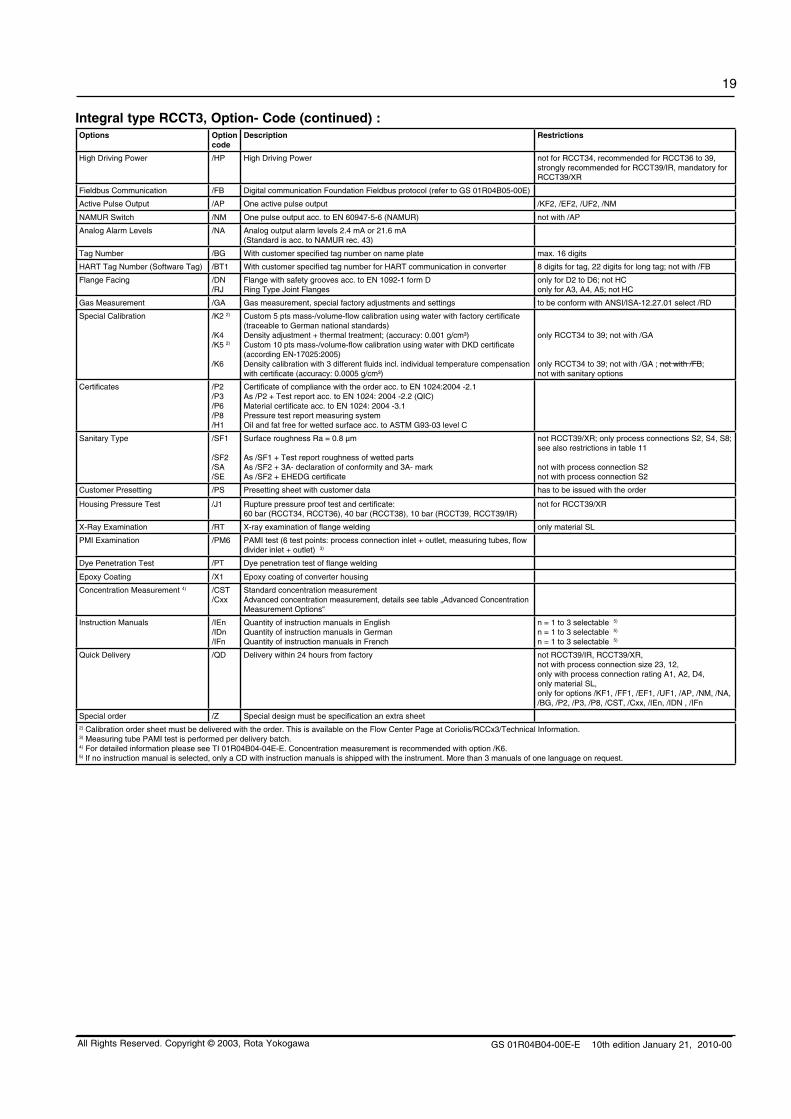
Integral type RCCT3, Option- Code (continued) :Options Option
codeDescription Restrictions
High Driving Power /HP High Driving Power not for RCCT34, recommended for RCCT36 to 39, strongly recommended for RCCT39/IR, mandatory for RCCT39/XR
Fieldbus Communication /FB Digital communication Foundation Fieldbus protocol (refer to GS 01R04B05-00E)
Active Pulse Output /AP One active pulse output /KF2, /EF2, /UF2, /NM
NAMUR Switch /NM One pulse output acc. to EN 60947-5-6 (NAMUR) not with /AP
Analog Alarm Levels /NA Analog output alarm levels 2.4 mA or 21.6 mA (Standard is acc. to NAMUR rec. 43)
Tag Number /BG With customer specified tag number on name plate max. 16 digits
HART Tag Number (Software Tag) /BT1 With customer specified tag number for HART communication in converter 8 digits for tag, 22 digits for long tag; not with /FB
Flange Facing /DN /RJ
Flange with safety grooves acc. to EN 1092-1 form DRing Type Joint Flanges
only for D2 to D6; not HConly for A3, A4, A5; not HC
Gas Measurement /GA Gas measurement, special factory adjustments and settings to be conform with ANSI/ISA-12.27.01 select /RD
Special Calibration /K2 2)
/K4 /K5 2)
/K6
Custom 5 pts mass-/volume-flow calibration using water with factory certificate (traceable to German national standards)Density adjustment + thermal treatment; (accuracy: 0.001 g/cm³) Custom 10 pts mass-/volume-flow calibration using water with DKD certificate (according EN-17025:2005)Density calibration with 3 different fluids incl. individual temperature compensation with certificate (accuracy: 0.0005 g/cm³)
only RCCT34 to 39; not with /GA
only RCCT34 to 39; not with /GA ; not with /FB; not with sanitary options
Certificates /P2/P3/P6/P8/H1
Certificate of compliance with the order acc. to EN 1024:2004 -2.1As /P2 + Test report acc. to EN 1024: 2004 -2.2 (QIC)Material certificate acc. to EN 1024: 2004 -3.1Pressure test report measuring systemOil and fat free for wetted surface acc. to ASTM G93-03 level C
Sanitary Type /SF1
/SF2/SA/SE
Surface roughness Ra = 0.8 µm
As /SF1 + Test report roughness of wetted partsAs /SF2 + 3A- declaration of conformity and 3A- markAs /SF2 + EHEDG certificate
not RCCT39/XR; only process connections S2, S4, S8;see also restrictions in table 11
not with process connection S2not with process connection S2
Customer Presetting /PS Presetting sheet with customer data has to be issued with the order
Housing Pressure Test /J1 Rupture pressure proof test and certificate:60 bar (RCCT34, RCCT36), 40 bar (RCCT38), 10 bar (RCCT39, RCCT39/IR)
not for RCCT39/XR
X-Ray Examination /RT X-ray examination of flange welding only material SL
PMI Examination /PM6 PAMI test (6 test points: process connection inlet + outlet, measuring tubes, flow divider inlet + outlet) 3)
Dye Penetration Test /PT Dye penetration test of flange welding
Epoxy Coating /X1 Epoxy coating of converter housing
Concentration Measurement 4) /CST/Cxx
Standard concentration measurementAdvanced concentration measurement, details see table „Advanced Concentration Measurement Options“
Instruction Manuals /IEn/IDn /IFn
Quantity of instruction manuals in EnglishQuantity of instruction manuals in GermanQuantity of instruction manuals in French
n = 1 to 3 selectable 5)
n = 1 to 3 selectable 5)
n = 1 to 3 selectable 5)
Quick Delivery /QD Delivery within 24 hours from factory not RCCT39/IR, RCCT39/XR,not with process connection size 23, 12,only with process connection rating A1, A2, D4,only material SL,only for options /KF1, /FF1, /EF1, /UF1, /AP, /NM, /NA, /BG, /P2, /P3, /P8, /CST, /Cxx, /IEn, /IDN , /IFn
Special order /Z Special design must be specification an extra sheet2) Calibration order sheet must be delivered with the order. This is available on the Flow Center Page at Coriolis/RCCx3/Technical Information.3) Measuring tube PAMI test is performed per delivery batch.4) For detailed information please see TI 01R04B04-04E-E. Concentration measurement is recommended with option /K6.5) If no instruction manual is selected, only a CD with instruction manuals is shipped with the instrument. More than 3 manuals of one language on request.
GS 01R04B04-00E-E 10th edition January 21, 2010-00
20
All Rights Reserved. Copyright © 2003, Rota Yokogawa
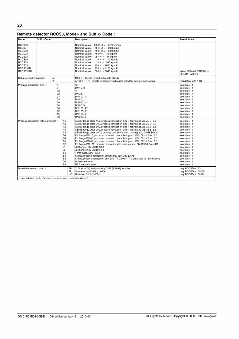
Remote detector RCCS3, Model- and Suffix- Code :Model Suffix Code Description Restrictions
RCCS30RCCS31RCCS32RCCS33RCCS34RCCS36RCCS38RCCS39RCCS39/IRRCCS39/XR
Nominal Value : 0.045 t/h = 0.75 kg/minNominal Value : 0.17 t/h = 2.8 kg/minNominal Value : 0.37 t/h = 6.2 kg/minNominal Value : 0.9 t/h = 15 kg/minNominal Value : 2.7 t/h = 45 kg/minNominal Value : 10 t/h = 170 kg/minNominal Value : 32 t/h = 533 kg/minNominal Value : 100 t/h = 1670 kg/minNominal Value : 250 t/h = 4170 kg/minNominal Value : 500 t/h = 8340 kg/min select affiliated RCCF31 or
RCCR31 with /HP
Cable conduit connection -M-A
M20 x 1, female thread with cable glandsANSI ½´´ NPT, female thread only with cable gland for detector connection mandatory with /FS1
Process connection size 1) 410123020405060810121520
¼´´DN 15, ½´´ ¾´´DN 25, 1´´DN 40, 1½´´DN 50, 2´´DN 65, 2½´´DN 80, 3´´DN 100, 4´´DN 125, 5´´DN 150, 6´´DN 200, 8´´
see table 11see table 11see table 11see table 11see table 11see table 11see table 11see table 11see table 11see table 11see table 11see table 11
Process connection rating and style 1) A1A2A3A4A5D2D4D5D6J1J2S2S4S8G9T9
ASME flange class 150, process connection dim. + facing acc. ASME B16.5ASME flange class 300, process connection dim. + facing acc. ASME B16.5ASME flange class 600, process connection dim. + facing acc. ASME B16.5ASME flange class 900, process connection dim. + facing acc. ASME B16.5ASME flange class 1500, process connection dim. + facing acc. ASME B16.5EN flange PN 16, process connection dim. + facing acc. EN 1092-1 Form B2EN flange PN 40, process connection dim. + facing acc. EN 1092-1 Form B2EN flange PN 63, process connection dim. + facing acc. EN 1092-1 Form B2EN flange PN 100, process connection dim. + facing acc. EN 1092-1 Form B2JIS flange 10K, JIS B 2220JIS flange 20K, JIS B 2220Thread acc. DIN 11851Clamp, process connection dimensions acc. DIN 32676Clamp, process connection dim. acc. Tri-Clover (Tri-Clamp) and ½´´ Mini ClampG, female threadNPT, female thread
see table 11see table 11see table 11see table 11see table 11see table 11see table 11see table 11see table 11see table 11see table 11see table 11see table 11see table 11see table 11see table 11
Material of wetted parts 1) SHSLHC
316L (1.4404) and Hastelloy C-22 (2.4602) for tubeStainless steel 316L (1.4404)Hastelloy C-22 (2.4602)
only RCCS30 to 33only RCCS34 to 39/XRonly RCCS34 to 39/IR
1) see selection table „Process connection and materials“ (table 11)

GS 01R04B04-00E-E 10th edition January 21, 2010-00
21
All Rights Reserved. Copyright © 2003, Rota Yokogawa
Remote detector RCCS3, Option- Code :Options Option
codeDescription Restrictions
Hazardous Area Approvals 1) /KS1/FS1/ES1/US1
ATEX intrinsically safe approvalFM approval for USA + CanadaIECEx intrinsically safe approvalINMETRO intrinsically safe approval for Brazil
only with cable conduit ´A´
Custody Transfer Measurement acc. OIML R 117-1
/Q01 European MID Approval (fluids other than water) (refer to GS 01R04B07-00E)
GOST Approval 1) /QR1/QR2/QR3
Russian GOST approvalKazakh GOST approvalUzbekistan GOST approval
see page 8; not with /LTsee page 8; not for RCCS39/XR; not with /LTsee page 8; not for RCCS39/XR; not with /LT
Dual Seal Approval /DS
/RD
Dual Seal approval (conform with ANSI/ISA-12.27.01)
Rupture disk
only RCCS34 to 39/XR; only with /FS1; not with process connection A5only RCCS34 to 39/IR, preferable with /GA, not with /Tx, mandatory if /DS + /GA is selected
Tag Number /BG With customer specified tag number on name plate max. 16 digits
Flange Facing /DN /RJ
Flange with safety grooves acc. to EN 1092-1 form DRing Type Joint Flanges
only for D2 to D6; not HConly for A3, A4, A5; not HC
Gas Measurement /GA Gas measurement, special factory adjustments and settings select affiliated RCCF31 or RCCR31 with /GA;to be conform with ANSI/ISA-12.27.01 select /RD
Low temperature version /LT -200°C < Tmedium < 150°C not RCCS30 to 33; not with /KS1, /FS1, /ES1, /US1, /MT, /HT, /T1, /T2, /T3, /QR1, /QR2, /QR3
Extended temperature range /MT -70°C < Tmedium < 230°C not RCCS30 to 33; always with /S2 or /Tx; remote cable RCCY033/034 recommended
High temperature version /HT Tmedium up to 350°C only with /Tx; only RCCS34 to 39/IR;remote cable RCCY033/034 recommended
Special Calibration /K2 2)
/K4 /K5 2)
/K6
Custom 5 pts mass-/volume-flow calibration using water with factory certificate (traceable to German national standards)Density adjustment + thermal treatment; (accuracy: 0.001 g/cm³) Custom 10 pts mass-/volume-flow calibration using water with DKD certificate (according EN-17025:2005)Density calibration with 3 different fluids incl. individual temperature compensation with certificate (accuracy: 0.0005 g/cm³)
only RCCS31 to 39; not with /GAnot RCCS30
only RCCS32 to 39; not with /GA; not with sanitary options; only available if converter is also ordered
Certificates /P2/P3/P6/P8/H1
Certificate of compliance with the order acc. to EN 1024:2004 -2.1As /P2 + Test report acc to EN 1024: 2004 -2.2 (QIC)Material certificate acc to EN 1024: 2004 -3.1Pressure test report measuring systemOil and fat free for wetted surface acc. to ASTM G93-03 level C
Sanitary Type /SF1
/SF2/SA/SE
Surface roughness Ra = 0.8 µm
As /SF1 + Test report roughness of wetted partsAs /SF2 + 3A- declaration of conformity and 3A- markAs /SF2 + EHEDG- certificate
only RCCS34 to 39/IR; only process connections S2, S4, S8; see also restrictions in table 11
not with process connection S2not with process connection S2
Mounting set /PD 2 inch pipe mounting set only RCCS30 to 33; not with /Tx; recommended for RCCS30
Housing Pressure Test /J1 Rupture pressure proof test and certificate:60 bar (RCCS34, RCCS36), 40 bar (RCCS38), 10 bar (RCCS39, RCCS39/IR)
not for RCCS30 to 33 + RCCS39/XR
Customer insulation / Heating /S2 Terminal box on extension for high or low process temperature not with /T1 ... /T3
Factory Insulating / Heating /T1/T2/T3
InsulationInsulation + Heat carrier heatingInsulation + Heat carrier heating with ventilation
not for RCCS39/XRnot for RCCS39/XRnot for RCCS39/XR
X-Ray Examination /RT X-ray examination of flange welding not with material HC
PMI Examination /PM4
/PM6
PAMI test (4 test points: process connection inlet + outlet, flow divider inlet + outlet) 3)
PAMI test (6 test points: process connection inlet + outlet, measuring tubes, flow divider inlet + outlet) 3)
only RCCS30 to 33
not RCCS30 to 33
Dye Penetration Test /PT Dye penetration test of flange welding
Stainless steel cable gland /BS Cable gland stainless steel
Quick Delivery /QD Delivery within 24 hours from factory only RCCS34 to 39not with process connection size 23, 12,only with process connection rating A1, A2, D4,only material SL,only for options /KS1, /FS1, /ES1, /US1, /BG, /P2, /P3, /P8
Special order /Z Special design must be specification an extra sheet1) Select affiliated converter RCCF31/RCCR31 with the same approval type (e.g. ATEX).2) Calibration order sheet must be delivered with the order. This is available on the Flow Center Page at Coriolis/RCCx3/Technical Information.3) Measuring tube PAMI test is performed per delivery batch.

GS 01R04B04-00E-E 10th edition January 21, 2010-00
22
All Rights Reserved. Copyright © 2003, Rota Yokogawa
Remote field-mount converter RCCF31, Model-, Suffix- and Option- Code :Model Suffix Code Option
CodeDescription Restrictions
RCCF31 Remote field-mount converter to be connected to RCCS3;when ordered without detector combination option /NC must be selected
Power supply -A-D
90 - 264 V AC24 V DC
Indicator direction H2N0
With indicatorWithout indicator
Cable conduit connection MA
M20 x 1, female thread with cable glandsANSI ½´´ NPT, female thread, only cable gland for detector connection mandatory with /FF1, /FF3
Hazardous Area Approvals 2) /KF1/KF2/FF1
/EF1/EF2/UF1/UF2
ATEX Flame proof converter + Intrinsic safe detectorATEX Flame proof converter + Intrinsic safe detector + Intrinsic safe outputs 1) FM approval for USA+Canada, Flame proof converter + Intrinsic safe detector
IECEx Flame proof converter + Intrinsic safe detectorIECEx Flame proof converter + Intrinsic safe detector + Intrinsic safe outputs 1) INMETRO Flame proof converter + Intrinsic safe detectorINMETRO Flame proof converter + Intrinsic safe detector + Intrinsic safe outputs 1)
with /HP for gas group IIBwith /HP for gas group IIBonly with cable conduit ´A´; with /HP not for groups A and Bwith /HP for gas group IIBwith /HP for gas group IIBwith /HP for gas group IIBwith /HP for gas group IIB
Custody Transfer Measurement acc. OIML R 117-1
/Q01 European MID Approval (fluids other than water) (refer to GS 01R04B07-00E)
GOST Approval 2) /QR1/QR2/QR3
Russian GOST approvalKazakh GOST approvalUzbekistan GOST approval
see page 8see page 8; not with /HPsee page 8; not with /HP
Fieldbus Communication /FB Digital communication (Foundation Fieldbus protocol refer to GS 01R04B05-00E)
High Driving Power /HP High Driving Power not for combination with RCCS30 to 34, recommended for combination with RCCS36 to 39, strongly recommended for combination with RCCS39/IR, mandatory for combination with RCCS39/XR
Active Pulse Output /AP One active pulse output /KF2, /EF2, /UF2, /NM
NAMUR Switch /NM One pulse output acc. EN 60947-5-6 (NAMUR) not with /AP
Analog Alarm Levels /NA Analog output alarm levels 2.4 mA or 21.6 mA (Standard is acc. NAMUR rec. 43)
Tag Number /BG With customer specified tag number on name plate max. 16 digits
HART Tag Number (Software Tag) /BT1 With customer specified tag number for HART communication in converter 8 digits for tag, 22 digits for long tag
Gas Measurement /GA Gas measurement, special factory adjustments and settings select affiliated RCCS3 with /GA
No Combination /NC No combination with detector
Customer Presetting /PS Presetting sheet with customer data has to be issued with the order
Epoxy Coating /X1 Epoxy coating of converter housing
Concentration Measurement 3) /CST/Cxx
Standard concentration measurementAdvanced concentration measurement, details see table „Advanced Concentration Measurement Options“
Instruction Manuals /IEn/IDn /IFn
Quantity of instruction manuals in EnglishQuantity of instruction manuals in GermanQuantity of instruction manuals in French
n = 1 to 3 selectable 4)
n = 1 to 3 selectable 4)
n = 1 to 3 selectable 4)
Quick Delivery /QD Delivery within 24 hours from factory not with /KF2, EF2, /UF2, /GA, /QR1, /QR2, /QR3, /PS, /X1
Special order /Z Special design must be specification an extra sheet1) This is a flame proof device, not an intrinsic safe device!2) Select affiliated RCCS3 with the same approval type (e.g. /KFx with /KS1).3) For detailed information please see TI 01R04B04-04E-E. Option /K6 of RCCS3 is recommended with concentration measurement. 4) If no instruction manual is selected, only a CD with instruction manuals is shipped with the instrument. More than 3 manuals of one language on request.

GS 01R04B04-00E-E 10th edition January 21, 2010-00
23
All Rights Reserved. Copyright © 2003, Rota Yokogawa
Remote cable RCCY03, Model-, Suffix- and Option- Code :Model Suffix Code Option
CodeDescription Restrictions
RCCY031RCCY032RCCY033RCCY034
Length in ´meter´Length in ´feet´Length in ´meter´Length in ´feet´
max. ambient temperature 70°C; with /FFx or /FS1: 50°Cmax. ambient temperature 70°C; with /FFx or /FS1: 50°Cmax. ambient temperature 105°C; with /FFx or /FS1: 85°Cmax. ambient temperature 105°C; with /FFx or /FS1: 85°C
Cable ends -0-1
No termination, with one termination kitTerminated not RCCY033
Cable length Lxxx Enter the length max. 300m / 999ft (with /FFx or /FS1 max. 50m / 165ft);the following lengths can be ordered (e.g. 3m = L003):RCCY031-0: 3m, 5m, 10m, 15m, 30m, 50m, 100m, 150m, 200m, 250m, 300mRCCY031-1: 3m, 5m, 10m, 15m, 30m, 50mRCCY032-0: 10ft, 15ft, 30ft, 50ft, 100ft, 150ft, 300ft, 500ft, 1000ftRCCY032-1: 10ft, 15ft, 30ft, 50ft, 100ft, 150ftRCCY033-0: 3m, 5m, 10m, 15m, 50m, 100m, 150m, 300mRCCY034-0: 10ft, 30ft, 50ft, 100ft, 150ft, 300ft, 500ft, 1000ftRCCY034-1: 10ft, 15ft, 30ft, 50ft, 100ft, 150ft
Options:Hazardous area installation Termination kitsQuick delivery
/KS1/TKxx/QD
Blue cable for Ex-i indicationQuantity of additional termination kitsDelivery within 24 hours from factory
xx = 01 to 99only RCCY031-1, L003, L005, L010
Remote rack-mount converter RCCR31, Model-, Suffix- and Option- Code :Model Suffix Code Option
CodeDescription Restrictions
RCCR31 Remote converter for 19´´ rack mounting to be connected to RCCS3
Power supply -A-D
90 - 264 V AC24 V DC
Hazardous Area Approvals 1) /KS1/FS1/ES1/US1
ATEX associated apparatus for intrinsic safe detector connection for gas group IICFM associated apparatus for intrinsic safe detector connectionIECEx associated apparatus for intrinsic safe detector connection for gas group IICINMETRO associated apparatus for intrinsic safe detector connection for gas group IIC
with /HP for gas group IIBwith /HP not for gas groups A and Bwith /HP for gas group IIBwith /HP for gas group IIB
GOST Approval 1) /QR1 Russian GOST approval see page 8
High Driving Power /HP High Driving Power not for combination with RCCS30 to 34, recommended for combination with RCCS36 to 39, strongly recom-mended for combination with RCCS39/IR, mandatory for combination with RCCS39/XR
Active Pulse Output /AP One active pulse output not with /NM
NAMUR Switch /NM One pulse output acc. EN 60947-5-6 (NAMUR) not with /AP
Analog Alarm Levels /NA Analog output alarm levels 2.4 mA or 21.6 mA (Standard is acc. NAMUR rec. 43)
Tag Number /BG With customer specified tag number on name plate max. 16 digits
HART Tag Number (Software Tag) /BT1 With customer specified tag number for HART communication in converter 8 digits for tag, 22 digits for long tag
Gas Measurement /GA Gas measurement, special factory adjustments and settings select affiliated RCCS3 with /GA
No Combination /NC No combination with detector
Customer Presetting /PS Presetting sheet with customer data has to be issued with the order
Concentration Measurement 2) /CST/Cxx
Standard concentration measurementAdvanced concentration measurement, details see table „Advanced Concentration Measurement Options“
Subrack /SR1/SR2
Subrack for 2 converter RCCR31 with mountingSubrack for 4 converter RCCR31 with mounting
Instruction Manuals /IEn/IDn /IFn
Quantity of instruction manuals in EnglishQuantity of instruction manuals in GermanQuantity of instruction manuals in French
n = 1 to 3 selectable 3)
n = 1 to 3 selectable 3)
n = 1 to 3 selectable 3)
Special order /Z Special design must be specification an extra sheet1) Select affiliated RCCS3 with the same approval type (e.g. /KS1 with /KS1).2) For detailed information please see TI 01R04B04-04E-E. Option /K6 of RCCS3 is recommended with concentration measurement.3) If no instruction manual is selected, only a CD with instruction manuals is shipped with the instrument. More than 3 manuals of one language on request.

GS 01R04B04-00E-E 10th edition January 21, 2010-00
24
All Rights Reserved. Copyright © 2003, Rota Yokogawa
Advanced Concentration Measurement Options (others on request), recommended with option /K6:Option Display Components Concentration
rangeTemp. range Source of concentration- / density table
/C01 °Brix Sugar / Water 0 - 85 °Brix 0 - 80°C PTB- Messages 100 5/90:„The density of watery Saccarose solutions after the introduction of the international tempera-
ture scale of 1990 (ITS1990)“ Table 5
/C02 WT% NaOH / Water 2 - 50 WT% 0 - 100°C D´Ans-Lax, Handbook for chemists and physicists Vol.1, 3rd edition, 1967
/C03 WT% KOH / Water 0 - 60 WT% 54 - 100°C D´Ans-Lax, Handbook for chemists and physicists Vol.1, 3rd edition, 1967
/C04 WT% NH4NO3 / Water 1 - 50 WT% 0 - 80°C Source undefined
/C05 WT% NH4NO3 / Water 20 - 70 WT% 20 - 100°C Source undefined
/C06 1) WT% HCl / Water 22 - 34 WT% 20 - 40°C D´Ans-Lax, Handbook for chemists and physicists Vol.1, 3rd edition, 1967
/C07 WT% HNO3 / Water 50 - 67 WT% 10 - 60°C Source undefined
/C09 WT% H2O2 / Water 30 - 75 WT% 4 - 44°C Source undefined
/C10 WT% Ethylene Glycol / Water 10 - 50 WT% -20 - 40°C Source undefined
/C11 WT% Amylum = starch / Water 33 - 43 WT% 35 - 45°C Source undefined
/C12 WT% Methanol / Water 35 - 60 WT% 0 - 40°C Source undefined
/C20 VOL% Alcohol / Water 55 - 100 VOL% 10 - 40°C Source undefined
/C21 °Brix Sugar / Water 40 - 80 °Brix 75 - 100°C Source undefined
1) only with material HC
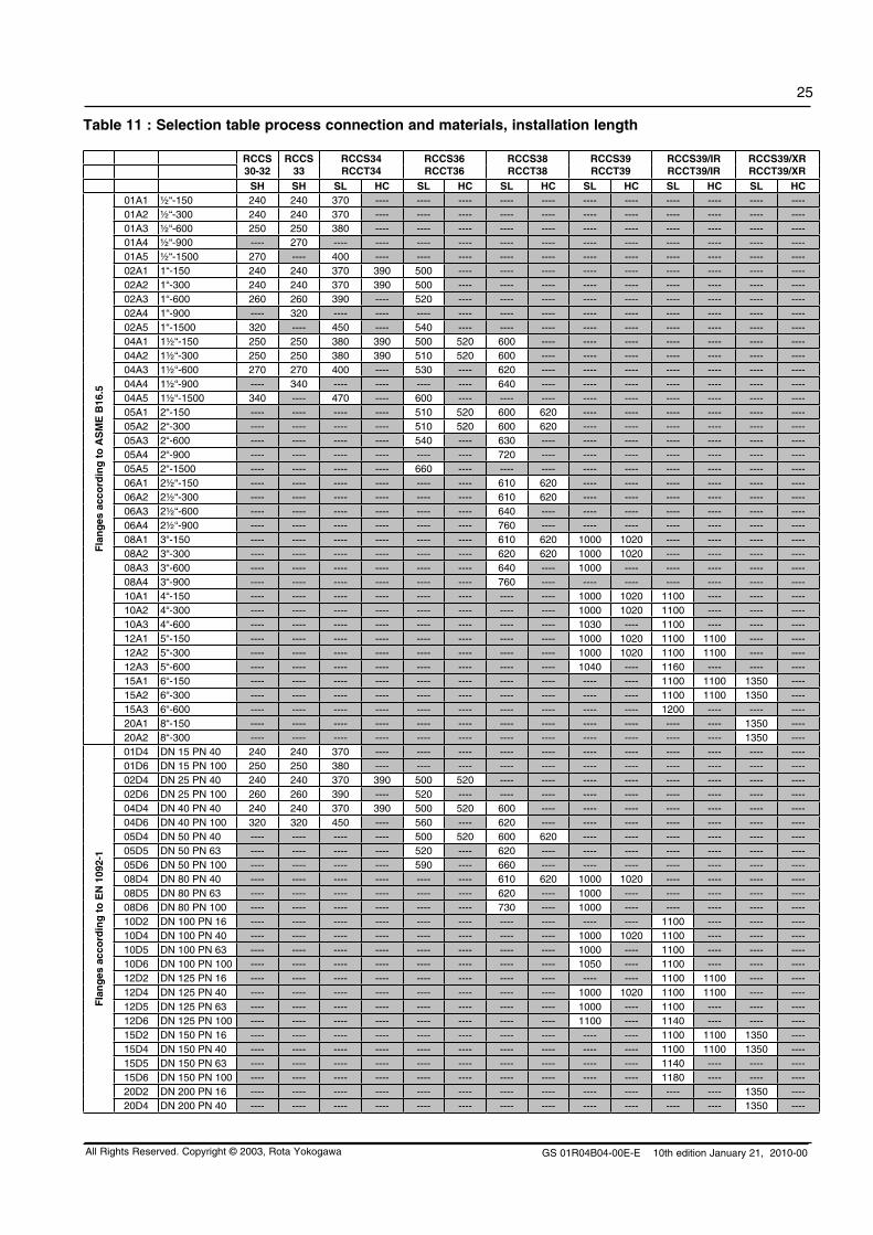
GS 01R04B04-00E-E 10th edition January 21, 2010-00
25
All Rights Reserved. Copyright © 2003, Rota Yokogawa
Table 11 : Selection table process connection and materials, installation length
RCCS30-32
RCCS33
RCCS34RCCT34
RCCS36RCCT36
RCCS38RCCT38
RCCS39RCCT39
RCCS39/IRRCCT39/IR
RCCS39/XRRCCT39/XR
SH SH SL HC SL HC SL HC SL HC SL HC SL HC
Fla
ng
es a
cco
rdin
g t
o A
SM
E B
16.5
01A1 ½“-150 240 240 370 ---- ---- ---- ---- ---- ---- ---- ---- ---- ---- ----01A2 ½“-300 240 240 370 ---- ---- ---- ---- ---- ---- ---- ---- ---- ---- ----01A3 ½“-600 250 250 380 ---- ---- ---- ---- ---- ---- ---- ---- ---- ---- ----01A4 ½“-900 ---- 270 ---- ---- ---- ---- ---- ---- ---- ---- ---- ---- ---- ----01A5 ½“-1500 270 ---- 400 ---- ---- ---- ---- ---- ---- ---- ---- ---- ---- ----02A1 1“-150 240 240 370 390 500 ---- ---- ---- ---- ---- ---- ---- ---- ----02A2 1“-300 240 240 370 390 500 ---- ---- ---- ---- ---- ---- ---- ---- ----02A3 1“-600 260 260 390 ---- 520 ---- ---- ---- ---- ---- ---- ---- ---- ----02A4 1“-900 ---- 320 ---- ---- ---- ---- ---- ---- ---- ---- ---- ---- ---- ----02A5 1“-1500 320 ---- 450 ---- 540 ---- ---- ---- ---- ---- ---- ---- ---- ----04A1 1½“-150 250 250 380 390 500 520 600 ---- ---- ---- ---- ---- ---- ----04A2 1½“-300 250 250 380 390 510 520 600 ---- ---- ---- ---- ---- ---- ----04A3 1½“-600 270 270 400 ---- 530 ---- 620 ---- ---- ---- ---- ---- ---- ----04A4 1½“-900 ---- 340 ---- ---- ---- ---- 640 ---- ---- ---- ---- ---- ---- ----04A5 1½“-1500 340 ---- 470 ---- 600 ---- ---- ---- ---- ---- ---- ---- ---- ----05A1 2“-150 ---- ---- ---- ---- 510 520 600 620 ---- ---- ---- ---- ---- ----05A2 2“-300 ---- ---- ---- ---- 510 520 600 620 ---- ---- ---- ---- ---- ----05A3 2“-600 ---- ---- ---- ---- 540 ---- 630 ---- ---- ---- ---- ---- ---- ----05A4 2“-900 ---- ---- ---- ---- ---- ---- 720 ---- ---- ---- ---- ---- ---- ----05A5 2“-1500 ---- ---- ---- ---- 660 ---- ---- ---- ---- ---- ---- ---- ---- ----06A1 2½“-150 ---- ---- ---- ---- ---- ---- 610 620 ---- ---- ---- ---- ---- ----06A2 2½“-300 ---- ---- ---- ---- ---- ---- 610 620 ---- ---- ---- ---- ---- ----06A3 2½“-600 ---- ---- ---- ---- ---- ---- 640 ---- ---- ---- ---- ---- ---- ----06A4 2½“-900 ---- ---- ---- ---- ---- ---- 760 ---- ---- ---- ---- ---- ---- ----08A1 3“-150 ---- ---- ---- ---- ---- ---- 610 620 1000 1020 ---- ---- ---- ----08A2 3“-300 ---- ---- ---- ---- ---- ---- 620 620 1000 1020 ---- ---- ---- ----08A3 3“-600 ---- ---- ---- ---- ---- ---- 640 ---- 1000 ---- ---- ---- ---- ----08A4 3“-900 ---- ---- ---- ---- ---- ---- 760 ---- ---- ---- ---- ---- ---- ----10A1 4“-150 ---- ---- ---- ---- ---- ---- ---- ---- 1000 1020 1100 ---- ---- ----10A2 4“-300 ---- ---- ---- ---- ---- ---- ---- ---- 1000 1020 1100 ---- ---- ----10A3 4“-600 ---- ---- ---- ---- ---- ---- ---- ---- 1030 ---- 1100 ---- ---- ----12A1 5“-150 ---- ---- ---- ---- ---- ---- ---- ---- 1000 1020 1100 1100 ---- ----12A2 5“-300 ---- ---- ---- ---- ---- ---- ---- ---- 1000 1020 1100 1100 ---- ----12A3 5“-600 ---- ---- ---- ---- ---- ---- ---- ---- 1040 ---- 1160 ---- ---- ----15A1 6“-150 ---- ---- ---- ---- ---- ---- ---- ---- ---- ---- 1100 1100 1350 ----15A2 6“-300 ---- ---- ---- ---- ---- ---- ---- ---- ---- ---- 1100 1100 1350 ----15A3 6“-600 ---- ---- ---- ---- ---- ---- ---- ---- ---- ---- 1200 ---- ---- ----20A1 8“-150 ---- ---- ---- ---- ---- ---- ---- ---- ---- ---- ---- ---- 1350 ----20A2 8“-300 ---- ---- ---- ---- ---- ---- ---- ---- ---- ---- ---- ---- 1350 ----
Fla
ng
es a
cco
rdin
g t
o E
N 1
092-
1
01D4 DN 15 PN 40 240 240 370 ---- ---- ---- ---- ---- ---- ---- ---- ---- ---- ----01D6 DN 15 PN 100 250 250 380 ---- ---- ---- ---- ---- ---- ---- ---- ---- ---- ----02D4 DN 25 PN 40 240 240 370 390 500 520 ---- ---- ---- ---- ---- ---- ---- ----02D6 DN 25 PN 100 260 260 390 ---- 520 ---- ---- ---- ---- ---- ---- ---- ---- ----04D4 DN 40 PN 40 240 240 370 390 500 520 600 ---- ---- ---- ---- ---- ---- ----04D6 DN 40 PN 100 320 320 450 ---- 560 ---- 620 ---- ---- ---- ---- ---- ---- ----05D4 DN 50 PN 40 ---- ---- ---- ---- 500 520 600 620 ---- ---- ---- ---- ---- ----05D5 DN 50 PN 63 ---- ---- ---- ---- 520 ---- 620 ---- ---- ---- ---- ---- ---- ----05D6 DN 50 PN 100 ---- ---- ---- ---- 590 ---- 660 ---- ---- ---- ---- ---- ---- ----08D4 DN 80 PN 40 ---- ---- ---- ---- ---- ---- 610 620 1000 1020 ---- ---- ---- ----08D5 DN 80 PN 63 ---- ---- ---- ---- ---- ---- 620 ---- 1000 ---- ---- ---- ---- ----08D6 DN 80 PN 100 ---- ---- ---- ---- ---- ---- 730 ---- 1000 ---- ---- ---- ---- ----10D2 DN 100 PN 16 ---- ---- ---- ---- ---- ---- ---- ---- ---- ---- 1100 ---- ---- ----10D4 DN 100 PN 40 ---- ---- ---- ---- ---- ---- ---- ---- 1000 1020 1100 ---- ---- ----10D5 DN 100 PN 63 ---- ---- ---- ---- ---- ---- ---- ---- 1000 ---- 1100 ---- ---- ----10D6 DN 100 PN 100 ---- ---- ---- ---- ---- ---- ---- ---- 1050 ---- 1100 ---- ---- ----12D2 DN 125 PN 16 ---- ---- ---- ---- ---- ---- ---- ---- ---- ---- 1100 1100 ---- ----12D4 DN 125 PN 40 ---- ---- ---- ---- ---- ---- ---- ---- 1000 1020 1100 1100 ---- ----12D5 DN 125 PN 63 ---- ---- ---- ---- ---- ---- ---- ---- 1000 ---- 1100 ---- ---- ----12D6 DN 125 PN 100 ---- ---- ---- ---- ---- ---- ---- ---- 1100 ---- 1140 ---- ---- ----15D2 DN 150 PN 16 ---- ---- ---- ---- ---- ---- ---- ---- ---- ---- 1100 1100 1350 ----15D4 DN 150 PN 40 ---- ---- ---- ---- ---- ---- ---- ---- ---- ---- 1100 1100 1350 ----15D5 DN 150 PN 63 ---- ---- ---- ---- ---- ---- ---- ---- ---- ---- 1140 ---- ---- ----15D6 DN 150 PN 100 ---- ---- ---- ---- ---- ---- ---- ---- ---- ---- 1180 ---- ---- ----20D2 DN 200 PN 16 ---- ---- ---- ---- ---- ---- ---- ---- ---- ---- ---- ---- 1350 ----20D4 DN 200 PN 40 ---- ---- ---- ---- ---- ---- ---- ---- ---- ---- ---- ---- 1350 ----

GS 01R04B04-00E-E 10th edition January 21, 2010-00
26
All Rights Reserved. Copyright © 2003, Rota Yokogawa
Table 11 : Selection table process connection and materials, installation length (continued)
RCCS30-32
RCCS33
RCCS34RCCT34
RCCS36RCCT36
RCCS38RCCT38
RCCS39RCCT39
RCCS39/IRRCCT39/IR
RCCS39/XRRCCT39/XR
SH SH SL HC SL HC SL HC SL HC SL HC SL HC
Fla
ng
es a
cco
rdin
g t
o J
IS B
222
0
01J1 DN 15 10K 240 240 370 ---- ---- ---- ---- ---- ---- ---- ---- ---- ---- ----01J2 DN 15 20K 240 240 370 ---- ---- ---- ---- ---- ---- ---- ---- ---- ---- ----02J1 DN 25 10K 240 240 370 390 500 ---- ---- ---- ---- ---- ---- ---- ---- ----02J2 DN 25 20K 240 240 370 390 500 ---- ---- ---- ---- ---- ---- ---- ---- ----04J1 DN 40 10K 240 240 370 390 500 520 600 ---- ---- ---- ---- ---- ---- ----04J2 DN 40 20K 240 240 370 390 500 520 600 ---- ---- ---- ---- ---- ---- ----05J1 DN 50 10K ---- ---- ---- ---- 500 520 600 620 ---- ---- ---- ---- ---- ----05J2 DN 50 20K ---- ---- ---- ---- 500 520 600 620 ---- ---- ---- ---- ---- ----08J1 DN 80 10K ---- ---- ---- ---- ---- ---- 600 620 1000 1020 ---- ---- ---- ----08J2 DN 80 20K ---- ---- ---- ---- ---- ---- 600 620 1000 1020 ---- ---- ---- ----10J1 DN 100 10K ---- ---- ---- ---- ---- ---- ---- ---- 1000 1020 1100 ---- ---- ----10J2 DN 100 20K ---- ---- ---- ---- ---- ---- ---- ---- 1000 1020 1100 ---- ---- ----
12J1 DN 125 10K ---- ---- ---- ---- ---- ---- ---- ---- 1000 1020 1100 1100 ---- ----
12J2 DN 125 20K ---- ---- ---- ---- ---- ---- ---- ---- 1000 1020 1100 1100 ---- ----15J1 DN 150 10K ---- ---- ---- ---- ---- ---- ---- ---- ---- ---- 1100 1100 ---- ----15J2 DN 150 20K ---- ---- ---- ---- ---- ---- ---- ---- ---- ---- 1100 1100 ---- ----
Cla
mp
DIN
01S4 DN 15 240 240 ---- ---- ---- ---- ---- ---- ---- ---- ---- ---- ---- ----02S4 DN 25 240 240 370 *) ---- ---- ---- ---- ---- ---- ---- ---- ---- ---- ----04S4 DN 40 240 240 370 ---- 500 *) ---- ---- ---- ---- ---- ---- ---- ---- ----05S4 DN 50 ---- ---- ---- ---- 500 ---- 600 *) ---- ---- ---- ---- ---- ---- ----06S4 DN 65 ---- ---- ---- ---- ---- ---- 600 ---- ---- ---- ---- ---- ---- ----10S4 DN 100 ---- ---- ---- ---- ---- ---- ---- ---- 1000 ---- ---- ---- ---- ----
Tri
-Cla
mp
01S8 ½“ 240 240 ---- ---- ---- ---- ---- ---- ---- ---- ---- ---- ---- ----02S8 1“ 240 240 370 *) ---- ---- ---- ---- ---- ---- ---- ---- ---- ---- ----04S8 1½“ 240 240 370 ---- 500 *) ---- ---- ---- ---- ---- ---- ---- ---- ----05S8 2“ ---- ---- ---- ---- 500 ---- 600 *) ---- ---- ---- ---- ---- ---- ----08S8 3“ ---- ---- ---- ---- ---- ---- 600 ---- ---- ---- ---- ---- ---- ----10S8 4“ ---- ---- ---- ---- ---- ---- ---- ---- 1000 ---- ---- ---- ---- ----
DIN
1185
1 02S2 DN 25 240 240 370 ---- ---- ---- ---- ---- ---- ---- ---- ---- ---- ----04S2 DN 40 ---- ---- ---- ---- 500 ---- ---- ---- ---- ---- ---- ---- ---- ----05S2 DN 50 ---- ---- ---- ---- ---- ---- 600 ---- ---- ---- ---- ---- ---- ----10S2 DN 100 ---- ---- ---- ---- ---- ---- ---- ---- 1000 ---- ---- ---- ---- ----41G9 G¼“ female 260 260 ---- ---- ---- ---- ---- ---- ---- ---- ---- ---- ---- ----01G9 G½“ female 260 260 390 ---- ---- ---- ---- ---- ---- ---- ---- ---- ---- ----23G9 G¾“ female 260 260 390 ---- ---- ---- ---- ---- ---- ---- ---- ---- ---- ----41T9 NPT¼“ female 260 260 ---- ---- ---- ---- ---- ---- ---- ---- ---- ---- ---- ----01T9 NPT½“ female 260 260 390 ---- ---- ---- ---- ---- ---- ---- ---- ---- ---- ----23T9 NPT¾“ female 260 260 390 ---- ---- ---- ---- ---- ---- ---- ---- ---- ---- ----
*) not possible with Option SFx, SA, SE

GS 01R04B04-00E-E 10th edition January 21, 2010-00
27
All Rights Reserved. Copyright © 2003, Rota Yokogawa

GS 01R04B04-00E-E 10th edition January 21, 2010-00
28
All Rights Reserved. Copyright © 2003, Rota Yokogawa
Yokogawa has an extensive sales and distribution network. Please refer to the European website (www.yokogawa.com/eu) to contact your nearest representative.
Euroweg 23825 HD AMERSFOORTThe Netherlandswww.yokogawa.com/eu
YOKOGAWA ELECTRIC CORPORATIONWorld Headquarters9-32, Nakacho 2-chome, Musashino-shiTokyo 180-8750Japanwww.yokogawa.com
YOKOGAWA CORPORATION OF AMERICA2 Dart RoadNewnan GA 30265USAwww.yokogawa.com/us
YOKOGAWA ELECTRIC ASIA Pte. LTD.5 Bedok South RoadSingapore 469270Singaporewww.yokogawa.com/sg
YOKOGAWA CHINA CO. LTD.3F Tower D Cartelo Crocodile BuildingNo.568 West Tianshan Road Changing DistrictShanghai, Chinawww.yokogawa.com/cn
YOKOGAWA MIDDLE EAST B.S.C.(c)P.O. Box 10070, ManamaBuilding 577, Road 2516, Busaiteen 225Muharraq, Bahrainwww.yokogawa.com/bh
Subject to change without notice